1
XenoContiki
Paul Harvey - 0501942
Level 4 Project — March 25, 2009
Abstract
This report details the modification of Contiki, a wireless sensor network operating system, to allow it to run as a virtual domain over the Xen hypervisor. Also explained is how the simulation
was made possible by the use of a central domain to control the messages that are passed between
the virtual domains as well as an explanation of the inclusion of the Insense runtime to allow Insense, a component based networking language, to take advantage of the simulation environment.
The following document contains the design, implementation and operation considerations of the
simulation environment.
i
”Simulated disorder postulates perfect discipline”
Lao-Tzu
ii
Acknowledgments
I would like to show my gratitude for the following people for their help and input on the project:
Ross McIlroy, for his help with some of the finer points of configuring Xen.
Oliver Sharma, for his assistance with Insense.
Alexandros Koliousis, for his insights into the networking applications, comments on this report.
Prof. Joe Sventek for his help throughout the project in guiding its direction and his review of this
report as well as acting as the lost property office.
In general thanks to all of the above for being all round nice chaps.
iii
Education Use Consent
I hereby give my permission for this project to be shown to other University of Glasgow students
and to be distributed in an electronic format. Please note that you are under no obligation to sign
this declaration, but doing so would help future students.
Name:
Signature:
Contents
1
2
Introduction
1
1.1
Background . . . . . . . . . . . . . . . . . . . . . . . . . . . . . . . . . . . . . .
1
1.1.1
Wireless Sensor Networks . . . . . . . . . . . . . . . . . . . . . . . . . .
1
1.1.2
Testing In Wireless Sensor Networks . . . . . . . . . . . . . . . . . . . .
2
1.2
Aims . . . . . . . . . . . . . . . . . . . . . . . . . . . . . . . . . . . . . . . . . .
3
1.3
Document Outline . . . . . . . . . . . . . . . . . . . . . . . . . . . . . . . . . . .
3
Previous Work
4
2.1
XenoTiny . . . . . . . . . . . . . . . . . . . . . . . . . . . . . . . . . . . . . . .
4
2.2
Contiki . . . . . . . . . . . . . . . . . . . . . . . . . . . . . . . . . . . . . . . .
4
2.2.1
Protothreads . . . . . . . . . . . . . . . . . . . . . . . . . . . . . . . . .
4
2.2.2
Contiki Architecture . . . . . . . . . . . . . . . . . . . . . . . . . . . . .
5
2.2.3
Contiki Applications . . . . . . . . . . . . . . . . . . . . . . . . . . . . .
6
Contiki Testing . . . . . . . . . . . . . . . . . . . . . . . . . . . . . . . . . . . .
6
2.3.1
Cooja . . . . . . . . . . . . . . . . . . . . . . . . . . . . . . . . . . . . .
6
2.3.2
Netsim . . . . . . . . . . . . . . . . . . . . . . . . . . . . . . . . . . . .
8
2.3.3
MSP430 Instruction Simulator . . . . . . . . . . . . . . . . . . . . . . . .
8
Xen . . . . . . . . . . . . . . . . . . . . . . . . . . . . . . . . . . . . . . . . . .
8
2.4.1
Paravirtualisation . . . . . . . . . . . . . . . . . . . . . . . . . . . . . . .
8
2.4.2
Domain Management . . . . . . . . . . . . . . . . . . . . . . . . . . . . .
9
Xen Scheduler . . . . . . . . . . . . . . . . . . . . . . . . . . . . . . . . . . . . .
10
2.3
2.4
2.5
iv
v
2.6
2.7
2.8
3
10
2.6.1
Split Drivers . . . . . . . . . . . . . . . . . . . . . . . . . . . . . . . . .
11
Insense . . . . . . . . . . . . . . . . . . . . . . . . . . . . . . . . . . . . . . . .
11
2.7.1
XenoContiki and Insense . . . . . . . . . . . . . . . . . . . . . . . . . . .
12
AODV . . . . . . . . . . . . . . . . . . . . . . . . . . . . . . . . . . . . . . . . .
12
Building The Contiki Domain
14
3.1
Contiki Domain . . . . . . . . . . . . . . . . . . . . . . . . . . . . . . . . . . . .
14
3.1.1
Reference Operating Systems . . . . . . . . . . . . . . . . . . . . . . . .
14
3.1.2
Xen Domain Requirements . . . . . . . . . . . . . . . . . . . . . . . . . .
14
3.1.3
Contiki as the Mini-Os Application . . . . . . . . . . . . . . . . . . . . .
15
3.1.4
Compiling Contiki Against Mini-Os . . . . . . . . . . . . . . . . . . . . .
15
Xen Platform . . . . . . . . . . . . . . . . . . . . . . . . . . . . . . . . . . . . .
16
3.2.1
Creating The Xen Platform . . . . . . . . . . . . . . . . . . . . . . . . . .
16
Physical Resources . . . . . . . . . . . . . . . . . . . . . . . . . . . . . . . . . .
16
3.2
3.3
4
Xen Networking . . . . . . . . . . . . . . . . . . . . . . . . . . . . . . . . . . . .
Isolated XenoContiki
18
4.1
Debug Output . . . . . . . . . . . . . . . . . . . . . . . . . . . . . . . . . . . . .
18
4.2
LEDs . . . . . . . . . . . . . . . . . . . . . . . . . . . . . . . . . . . . . . . . .
19
4.3
Microcontroller Sleep . . . . . . . . . . . . . . . . . . . . . . . . . . . . . . . . .
19
4.4
Timers . . . . . . . . . . . . . . . . . . . . . . . . . . . . . . . . . . . . . . . . .
20
4.4.1
Contiki Timers . . . . . . . . . . . . . . . . . . . . . . . . . . . . . . . .
20
4.4.2
MSP430 Timers . . . . . . . . . . . . . . . . . . . . . . . . . . . . . . .
20
4.4.3
Xen Timers . . . . . . . . . . . . . . . . . . . . . . . . . . . . . . . . . .
21
4.4.4
Timer A . . . . . . . . . . . . . . . . . . . . . . . . . . . . . . . . . . . .
21
Hardware . . . . . . . . . . . . . . . . . . . . . . . . . . . . . . . . . . .
21
Xen: Timer A . . . . . . . . . . . . . . . . . . . . . . . . . . . . . . . . .
22
Timer B . . . . . . . . . . . . . . . . . . . . . . . . . . . . . . . . . . . .
22
4.4.5
vi
4.4.6
4.5
5
Xen Timer . . . . . . . . . . . . . . . . . . . . . . . . . . . . . . . . . .
23
IDS . . . . . . . . . . . . . . . . . . . . . . . . . . . . . . . . . . . . . . . . . .
23
4.5.1
24
Radio Communications
25
5.1
T-Mote Radio . . . . . . . . . . . . . . . . . . . . . . . . . . . . . . . . . . . . .
25
Hardware Components . . . . . . . . . . . . . . . . . . . . . . . . . . . .
25
Software Components . . . . . . . . . . . . . . . . . . . . . . . . . . . .
27
Netsim Radio . . . . . . . . . . . . . . . . . . . . . . . . . . . . . . . . .
28
Xen Radio . . . . . . . . . . . . . . . . . . . . . . . . . . . . . . . . . . . . . . .
28
5.2.1
Radio Emulation . . . . . . . . . . . . . . . . . . . . . . . . . . . . . . .
28
5.2.2
Control . . . . . . . . . . . . . . . . . . . . . . . . . . . . . . . . . . . .
30
5.2.3
Transmission . . . . . . . . . . . . . . . . . . . . . . . . . . . . . . . . .
31
5.2.4
Reception . . . . . . . . . . . . . . . . . . . . . . . . . . . . . . . . . . .
31
Simulated Radio Network . . . . . . . . . . . . . . . . . . . . . . . . . . . . . . .
32
5.3.1
Network Requirements . . . . . . . . . . . . . . . . . . . . . . . . . . . .
33
5.3.2
Network Design . . . . . . . . . . . . . . . . . . . . . . . . . . . . . . .
33
5.3.3
Network Mechanics . . . . . . . . . . . . . . . . . . . . . . . . . . . . .
33
Xen Implementation . . . . . . . . . . . . . . . . . . . . . . . . . . . . .
33
Protocol Choice . . . . . . . . . . . . . . . . . . . . . . . . . . . . . . . .
34
Xen Ether Componenets . . . . . . . . . . . . . . . . . . . . . . . . . . .
34
5.1.1
5.2
5.3
6
Xen Store . . . . . . . . . . . . . . . . . . . . . . . . . . . . . . . . . . .
Insense Runtime and XenoContiki
37
6.1
Insense Build Process . . . . . . . . . . . . . . . . . . . . . . . . . . . . . . . . .
37
6.2
Insense Modifications . . . . . . . . . . . . . . . . . . . . . . . . . . . . . . . . .
38
6.2.1
Insense Build Modifications . . . . . . . . . . . . . . . . . . . . . . . . .
38
6.2.2
Insense Runtime Modifications
. . . . . . . . . . . . . . . . . . . . . . .
38
6.2.3
XenoContiki Build Modifications . . . . . . . . . . . . . . . . . . . . . .
39
vii
6.2.4
7
8
Mini-Os Modifications . . . . . . . . . . . . . . . . . . . . . . . . . . . .
Topology Managment
39
40
7.0.5
Scripts . . . . . . . . . . . . . . . . . . . . . . . . . . . . . . . . . . . .
40
7.0.6
Domain ID . . . . . . . . . . . . . . . . . . . . . . . . . . . . . . . . . .
41
7.0.7
Domain Control Methods . . . . . . . . . . . . . . . . . . . . . . . . . .
41
7.0.8
Topology Creation . . . . . . . . . . . . . . . . . . . . . . . . . . . . . .
42
7.0.9
Modifying A Topology . . . . . . . . . . . . . . . . . . . . . . . . . . . .
43
Evaluation
45
8.1
Component Correctness . . . . . . . . . . . . . . . . . . . . . . . . . . . . . . . .
45
8.2
Simulator Correctness . . . . . . . . . . . . . . . . . . . . . . . . . . . . . . . . .
45
8.2.1
Hello World . . . . . . . . . . . . . . . . . . . . . . . . . . . . . . . . . .
46
8.2.2
Test abc . . . . . . . . . . . . . . . . . . . . . . . . . . . . . . . . . . . .
46
8.2.3
Test Polite . . . . . . . . . . . . . . . . . . . . . . . . . . . . . . . . . . .
46
8.2.4
Test Trickle . . . . . . . . . . . . . . . . . . . . . . . . . . . . . . . . . .
46
8.2.5
Test MeshRoute . . . . . . . . . . . . . . . . . . . . . . . . . . . . . . .
46
8.2.6
XMac Component . . . . . . . . . . . . . . . . . . . . . . . . . . . . . .
47
AODV . . . . . . . . . . . . . . . . . . . . . . . . . . . . . . . . . . . . . . . . .
47
8.3.1
Discovery Time . . . . . . . . . . . . . . . . . . . . . . . . . . . . . . . .
48
8.3.2
Packets Transmitted . . . . . . . . . . . . . . . . . . . . . . . . . . . . .
48
Performance . . . . . . . . . . . . . . . . . . . . . . . . . . . . . . . . . . . . . .
49
8.4.1
Timer Accuracy . . . . . . . . . . . . . . . . . . . . . . . . . . . . . . . .
49
8.4.2
Node Start Times . . . . . . . . . . . . . . . . . . . . . . . . . . . . . . .
52
8.4.3
Domain Size . . . . . . . . . . . . . . . . . . . . . . . . . . . . . . . . .
53
8.5
Experimental Setup . . . . . . . . . . . . . . . . . . . . . . . . . . . . . . . . . .
54
8.6
Insense . . . . . . . . . . . . . . . . . . . . . . . . . . . . . . . . . . . . . . . .
54
8.3
8.4
viii
9
Conclusion
55
9.1
Future Work . . . . . . . . . . . . . . . . . . . . . . . . . . . . . . . . . . . . . .
55
9.1.1
Radio Medium . . . . . . . . . . . . . . . . . . . . . . . . . . . . . . . .
55
9.1.2
XenoContiki Node . . . . . . . . . . . . . . . . . . . . . . . . . . . . . .
55
9.1.3
Insense . . . . . . . . . . . . . . . . . . . . . . . . . . . . . . . . . . . .
56
9.1.4
Xen . . . . . . . . . . . . . . . . . . . . . . . . . . . . . . . . . . . . . .
56
Project Achievements . . . . . . . . . . . . . . . . . . . . . . . . . . . . . . . . .
57
9.2
A Manual
60
Chapter 1
Introduction
The goals of this project were to create a new testing platform for Contiki, an operating system for
wireless sensor networks, that would allow accurate testing of programs; inclusion of the Insense
runtime within this new testing platform to allow Insense application’s to be tested and an implementation of an AODV application as a proof that the implementation was possible on the testing
platform. This project looks to expand upon the simulation technique established in the previous
work of XenoTiny [18]. Xen is a virtual machine monitor that allows for the virtualization of many
operating systems concurrently on a single machine’s hardware. The goal for simulation was to
successfully create Contiki domains and allow them to run concurrently as Xen guest domains.
1.1
Background
Before moving on it is important to have a basic understanding of what will be discussed at later
points in this project so as to have a feeling of reference. The more intricate details needed for
understanding of the main part of the project shall be discussed in Chapter 2.
1.1.1
Wireless Sensor Networks
A wireless sensor network is a collection of low cost sensor nodes which interact using radio communications. Typically nodes are able to sense features of the environment around them such as
temperature, humidity, vibration or light and then convey these readings to a central node. This
central node may present its data to a human user in some way, store this data as a record in a
database or respond to this data by affecting a change in the monitored environment. An example
of the latter being in an irrigation system for crops in that the sensors would note a lack of moisture
in the soil, convey this to the central node which in turn activates the sprinklers [3].
Each node in the network, also known as a mote, will typically contain a low power CPU(between
2 and 8 MHz) accompanied by a low power radio. The radio’s range varies between ten and a few
hundred meters and operate at a speed of around 250Kbps [4] to communicate with other nodes.
Nodes may also come with extra components, like the sensors mentioned before, depending on
what role they play within the network; some may be simply sensor nodes where as others may
1
2
be relays, which would not require the extra equipment. An important component of a node is
its power source which usually is a battery. Despite a combination of low power hardware and
considerate programming, a node would exhaust the battery after a few days of continuous use of
all components; it is therefore common place to ensure that a node will enter a low-power “sleep”
state while doing no work. This technique can extend the life of a mote battery up to 99 % resulting
in an increase from a few hours to years [13].
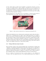
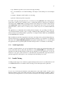
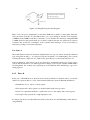
The nodes themselves are often small in size, as seen in Figure 1.1, with the greatest amount of
space being taken up by the casing for the battery, usually supporting two AA batteries.
Figure 1.1: Mote beside an American 25c coin. Intel Research, Berkeley [16]
Although each individual mote has a limited amount computational capacity, when networked together in tens or even hundreds they are capable of quite sophisticated activities. For example, a
wireless sensor network consisting of thousands of nodes was considered to replace land mines in
the sense that they would be used for monitoring and not cause harm to civilians after the conflict.
The idea was that as a node detected a disturbance, in the form of a vibration, it would activate a
camera that would record movement of the cause of the disturbance after which it would relay back
this data to its central node [1]. The book also mentions the interesting possible delivery methods
of these nodes ranging from an air drop to being “fired by artillery”.
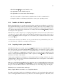
1.1.2
Testing In Wireless Sensor Networks
Due to the nature of wireless sensor networks and their usage, as described above, testing if often
a challenge. For example the environments that the networks are deployed in are often hazardous
to humans [21]. Given these difficulties, it often desirable for the deployment or modification to be
carried out only once at these locations. As a result of these constraints it is advantageous to carryout
exhaustive testing before deployment as coding errors could prove costly to rectify. In answer to
this real hardware testing or software emulation/simulation are the most common answers.
The use of simulators for testing has been used to produce guarantees as to the reliability and
correctness of the code running on the motes. For Contiki in particular there exists a number of
3
simulators that will be discussed in Section 2.3.1. In general simulators can be used to simulate the
behaviour of entire networks and are very useful testing tools.
1.2
Aims
The main aim of this project was to create XenoContiki. In essence this was a modified version
of the existing Contiki kernel that would work as a guest domain over the Xen hypervisor. This
could be seen much in the same way as modifying the kernel to work on a new hardware platform;
however in this case the platform was software.
The second aim of this project was to successfully compile and run Insense programs on each of
the XenoContiki domains by successful inclusion of the Insense runtime. The reasoning behind this
was driven by testing and would allow comparison against real systems to determine the correctness
of the simulation and eventually to be used as a testing mechanism for Insense before deployment.
The third aim of this project was to implement a version of the Ad hoc On-Demand Distance Vector
Routing (AODV) [20] routing protocol into the simulation so as to prove that an implementation of
the protocol was possible in the testing environment and to show that both the protocol and system
behaved normally as the number of nodes in the simulation increased.
1.3
Document Outline
The remainder of the dissertation consists of the following chapters:
• Project Context - Contiki, Xen, Insense, AODV (Chapter 2)
• Design and Build Process - Contiki-Xen Domain (Chapter 3)
• Timer Hardware Requirements of T-Mote Sky and Xen Emulation (Chapter 4)
• Radio Communications and Xen Emulation (Chapter 5)
• Insense - Build Process and Xen Modifications (Chapter 6)
• Topology Management - Running, viewing and modification of simulated nodes (Chapter
7)
• Testing and Evaluation (Chapter 8)
• Conclusion(Chapter 9)
Chapter 2
Previous Work
This section is intended to familiarise the reader with prior knowledge or work that may be pertinent
to the following sections of this document. First shall be a discussion of Contiki, as well as its
associated testing mechanisms, to give an overview of the operating system as a whole. Then an
explanation of Xen in terms of how to use it to create domains followed by a look at Insense, as its
integration is one of the main challenges of this project, and finally a look at the AODV protocol.
2.1
XenoTiny
The most helpful and notable prior work that has been completed was XenoTiny [18]. The project’s
goal was to create a network simulator with Xen except using TinyOS [12] instead of Contiki. Due
to the similar nature of the project many concepts were similar and the XenoTiny documentation
was extremely helpful in the creation of XenoContiki.
2.2
Contiki
Contiki is a multi-tasking operating system that is designed for memory constrained networked
embedded systems and wireless sensor networked devices, such as the T-mote sky or Mica. This
section discusses the three main features of Contiki starting with protothreads, light weight threads
that use little memory, followed by the architecture of Contiki and ending with a discussion of how
applications are included.
2.2.1
Protothreads
The normal process for writing software for embedded systems is to use the event-driven model
as this keeps the memory overhead low. This does tend to result in state machine like programming which can make the authoring quite difficult. Contiki presents a way of overcoming this and
allowing programmes to be written in an event-driven thread like style: protothreads [8].
4
5
Protothreads are extremely light weight stack-less threads, with each thread only incurring a 2 byte
overhead in memory unlike the Posix threads which would each require their own stack, resulting
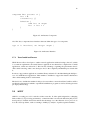
in a much higher overhead. Protothreads are also completely implemented in C without any assembly statements making them platform agnostic. The following is an example of the style that
protothreads afford [7].
# include ” pt . h”
struct pt pt ;
struct timer timer ;
PT THREAD ( e x a m p l e ( s t r u c t p t ∗ p t ) )
{
PT BEGIN ( p t ) ;
while ( 1 ) {
if ( initiate io ()) {
t i m e r s t a r t (& t i m e r ) ;
PT WAIT UNTIL ( p t ,
io completed () | |
t i m e r e x p i r e d (& t i m e r ) ) ;
read data ();
}
}
PT END ( p t ) ;
}
Figure 2.1: Protothread coding style
Protothreads run within a single c function and may not block within a called function. Blocking
functions are achieved by way of spawning a new protothread for each blocking call which makes
any blocking explicit. Protothreads are able to conditionally block or exit, just like Posix threads,
and are driven by repeated calls to the function that contains the protothreads.
Protothreads themselves are implemented using local continuations which represent the current
state of execution within a program but do not save any call history or local variables. Due to this,
it is Contiki’s author’s advice that local variables should be avoided in the use of protothreads or at
least used with the utmost care.
2.2.2
Contiki Architecture
Contiki is designed to be easily portable and to reflect this, the source tree is laid out in the following
manner:
• core - Main system code including hardware interfaces, the libraries and system header files
6
• cpu - Hardware specific code for each of the supported chips
• doc - Documentation on Contiki including a description of the build process and example
code
• examples - Examples with Contiki to use in testing
• platform - Platform specific components
In Contiki each supported platform has its own directory in the platform folder. Each platform
folder must contain at least a makefile, used to combine that platform’s build process within the
main build; a file contiki-conf.h, specifying particular values and global constants for that platform
and contiki-main.c which contains the kernel code for the platform. Any control code for specific
platform features, such as sensors or memory access control, may also be contained within this
folder.
The cpu directory complements this modular platform design by also providing a modular way
of storing the hardware specific code for a range of different chips. Each chip or microcontroller
directory can be reused in any number of platforms, for example both the T-Mote sky and MSB430
use the MSP430 microcontroller.
This modularity means that an application developer can simply write a platform independent application and specify at compile time which platform they intend it to be complied for. Compilation
takes the form of make TARGET=(platform) leaving the Contiki build process to correctly build
the application into the specified platform and the developer time to concentrate on other things.
2.2.3
Contiki Applications
Contiki is compiled with just one top level application that contains the particular thread that will
be run as the main. This is achieved by the inclusion of the AUTOSTART macro which links the
particular protothread with the kernel, which in turn schedules it as the application to be run. In
an effort to save space on the actual mote, each build will only include the components that the
particular application will require to run, as deciphered by the build process itself.
2.3
Contiki Testing
Contiki presently supports two methods of general testing in the from of Cooja and Netsim as well
as an MSP430 instruction set emulator. The following section shall explore these platforms.
2.3.1
Cooja
Cooja is one of the network simulation environments that comes with Contiki. It aims to give
full and complete control of the entire network as well as each individual node within it. This is
achieved by providing functions to monitor and even modify the nodes during a running simulation,
7
examples of these functions include fetching a node’s memory or pausing its execution. As this is
done in Java an object orientated style is used and each node is encapsulated by an object.
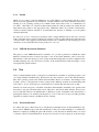
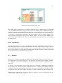
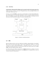
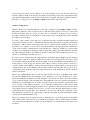
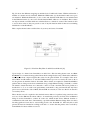
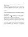
Figure 2.2: The different simulation levels compared to Cooja [10]
Cooja allows nodes to be abstracted at three different levels: application, operating system and
instruction set level, Figure 2.2. This is advantageous as it is not always required that all elements
of a sensor network need be abstracted at the same level. For example in a data collection network,
only the nodes closest to the sink may present the sufficient case to be simulated at a low level
whilst the others may be at a higher level, thus increasing the simulation’s performance [10].
Another obvious advantage of simulation or emulation is the ability to output debug output to a
console, one which Cooja takes advantage of. This is achieved by the inclusion of the log message()
statements that are provided by Contiki to be implemented by each platform as they see fit. These
statements allow for debug messages to be passed to a console within the Cooja application and
examined by the developer.
In Figure 2.2 a number of simulation levels are mentioned and each presents a different aspect of
testing.
At the top most level is application testing. At this level the correctness of the application is tested
to ensure that it is performing correctly by using the lower levels rather than to ensure that the
lower levels themselves are working. For example, the monitoring system discussed in Section
1.1.1 would be tested at this stage as it is the application that is being tested.
At the operating system level it is the actual components of the operating system that is tested
to ensure that they work correctly. For example, at this level it may be the timer component, to
ensure that events are being queued correctly, or the scheduler, to ensure that the chosen algorithm
is behaving correctly, that is being tested.
The lowest level of testing involves the simulated execution of the actual instructions that have been
generated after the previous two levels have been compiled for the target hardware. The goal of this
level is to provide a simulated circuit upon with the machine instructions can be used upon. At this
level testing can be used in placed of having the actual hardware and be used to guarantee that there
are no fundamental errors, such as trying to access restricted memory space or running instructions
that may not exist. This type of testing is, in some ways, better than on real hardware because the
full state of the circuit may be observed at any time in much the same way as a debugger like GDB.
8
2.3.2
Netsim
While Cooja is able to perform simulations at a wide number of varied levels, Netsim is more
directed towards application level simulation. Netsim simulates each node within the network by
running it as an operating system process which it then allows these nodes to communicate via
an “ether”. This ether is a software module which each node send its packets into which in turn
then delivers the packets to the appropriate node. Within the ether it is possible for interference,
collisions and any random elements to be included in the decision of whether or not the packet
should be delivered.
In order to be of use to a developer, Netsim provides a simple GUI that allows the user to interact
with a particular node as well as seeing the propagation of radio packets. Interaction takes the form
of mouse clicks on the graphical representation of the node to simulate its button being pressed. It
should also be noted that Netsim was the predecessor of Cooja.
2.3.3
MSP430 Instruction Simulator
The purpose of the MSP430 instruction simulator is to provide a platform on which the actual
hardware instructions that would be expected to run on the actual hardware can be tested [11].
The simulator offers the developer some security in the knowledge that even after compilation into
machine language, the code should run correctly on the actual hardware without having to worry
about platform specific features.
2.4
Xen
Xen is a virtual machine monitor (or hypervisor) which allows a number of operating systems to run
on a single machine simultaneously; Xen itself is the only element to run on the actual hardware.
The other operating systems run within virtual machines known as domains. Xen manages each
domain’s access to the physical resources and prevents different domains from interfering with
each other i.e. by two node trying to concurrently access and modify the same area on disk.
Xen has two main categories of domain: DomainU and Domain0. DomainU is the generic term
that refers to any guest domain, in this case it will refer to the XenoContiki domains, however it is
more commonly found as a modified Linux or Windows system. Domain0 on the other hand is a
privileged domain as it is started by the hypervisor on boot and serves as the controlling domain,
again this is usually found as a modified version of Linux .
2.4.1
Paravirtualisation
To achieve the above effect Xen uses a virtualisation technique known as Paravirtualisation [2].
Tools such as VMWare [5] provide full virtualisation. The goal of this technique is to emulate the
hardware completely, making the guest OS unaware of any abstraction and thus there is no need
to alter the software. Paravirtualisation, however, involves more work on the part of the developer
9
to modify the OS in order to use the features that Xen provides rather than just running, as with
virtualisation.
These features are accesed via a software ABI (Application Binary Interface) which consists of
the Xen hypercalls. These replace the system calls that would normally exist and are required
to perform privileged operations such as updating page tables or requesting access to hardware
resources. Although time must be spent in implementing these hypercalls the advantages come in
the form of a performance increase up to a factor of ten over other virtualisation techniques [23]. It
should be said that although the OS must be modified to run as a domain, any applications running
within the OS should remain unchanged.
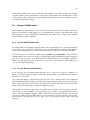
Figure 2.3: privilege levels in Xen [23]
As shown in Figure 2.3 Xen runs at level0, the most privileged position within the system, where
the operating system would normally run. Domain0 runs at level1 after which all other modified
“domains” are relegated to level2 and are still the most privileged elements of the system apart from
Domain0 and the Xen hypervisor. As mentioned above domains use hypercalls in place of system
calls however in order to receive any interrupts from the hypervisor each domain must register
to receive them. In Xen parlance this is known as “binding” and is achieved by using hypercalls
during a domain’s start of day activities to associate handlers in the domain with interrupt signals
that come from the hypervisor. These interrupts proved essential to this project in the replacement
of the hardware interrupts of the T-Mote sky and will be discussed in Section 4.4 and Chapter 5.
2.4.2
Domain Management
As alluded to above, Domain0 is the controlling domain as it is granted privileges by the hypervisor to access the hardware. This is achieved via the xm command. This command enables the
user to govern all aspects of domain management from creation and destruction to monitoring and
migration. The user must have root access to perform this command as it is a privileged one.
10
When creating a domain a configuration file must be specified to the create command, xm create
<file>. This file contains the domain’s specific details such as allotted memory size, the way in
which the domain will communicate with others (network interface, bridge, nat ...) as well as the
domain’s name. This too is of use in this project.
2.5
Xen Scheduler
In order to allow the concurrent running of multiple domains each domain is scheduled to run for
a specified amount, like a process within an OS, and it is the Xen scheduler that decides which
domain runs. There are many different types of scheduler but the one used as default by Xen is
known as the credit scheduler [2].
The credit scheduler schedules domains based on their priority. This priority is determined by one
of or both of the following factors. Firstly, a priority may be determined by a weighting that is
assigned at domain creation. For example, if a domain has a weight of 500 and another of 250, then
the first will be scheduled twice as much as the first. The second method, and the one used in this
project, involves capping the amount of CPU allocation to a domain. This capping is in terms of
CPU percentage ranging from 1% to 100%.
Now that a domain has a notion of priority it can now be split into two categories: over, a domain
has exceeded its fair share of resources, and under, a domain has not exceeded its fair share of
resources. When inserting a domain into the scheduler’s run queue it is placed after all domains of
equal priority. In order to more easily manage the priorities, they are represented by credits instead
of caps and weights. These credits are consumed as a domain runs and replenished by a system
wide accounting thread which calculates how much credit a domain is due and allocates it to that
domain.
Whenever a domain has completed its time slice, statically allocated at 30ms by Xen, or blocks the
next domain at the head of the run queue is chosen to run.
2.6
Xen Networking
Xen allows domains to communicate with each other by the use of virtual network interfaces. These
interfaces have two ends. The front end is found in a DomainU while the backend is found in
Domain0.
11
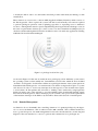
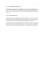
Figure 2.4: Xen networking setup [23]
This method allows all domains to communicate with and receive communications from Domain0
over virtual Ethernet interfaces. Figure 2.4 also shows the “xenbr0” which is an Ethernet bridge in
Domain0. This Ethernet bridge passes all traffic to the network interfaces that are connected to it,
virtual or otherwise, and it is this that allows DomainU’s to send messages to each other. Broadcast
of messages to all domains is prevented by the virtual interface (vif) not allowing packets of the
wrong IP address through. As the previous sentence implies, all vif’s have both hardware mac
address and software IP addresses. These are specified in the configuration file that is used during
domain creation.
2.6.1
Split Drivers
The final aspect of Xen to note is its split driver model. As only Domain0 is allowed access to
the underlying hardware all requests from domains other than dom0 must go through it. This is
achieved by split drivers. These are drivers that are, as one may guess, split into two parts with
the “frontend” being accessed by the particular domainU and the “backend” residing in Domain0
where actual access to the hardware may be granted.
2.7
Insense
Insense is a π-calculus based language that has been specifically designed for wireless sensor network applications. As well as being easy to use and learn, especially for non computer scientists,
it is designed to allow for the calculation of the worst case space and time complexities of programs [6].
π-calculus is one of the many process calculi, which are a collection of mathematical formalisms
used to analyse and describe concurrent computations whose configuration may change during the
calculation. This is not the main topic for this section however it is interesting to note that it contains
no primitives such as booleans, numbers, functions or even the common flow control structures [19].
The basic units of Insense are components which are similar to Java classes in that they are self
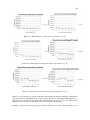
contained and require constructors [6].
12
component I n t s p r e s e n t s t 1 {
l a s t = 0;
c o n s t r u c t o r ( ) {}
behaviour {
s e n d l a s t on o u t p u t
l a s t := l a s t + 1
}
}
Figure 2.5: An Insense Component
Also like Java, components have interfaces that can define the types of a component.
type t1 i s i n t e r f a c e ( out i n t e g e r output )
Figure 2.6: An Insense Interface
2.7.1
XenoContiki and Insense
While Insense allows developers to author network applications without having to know C, which
is a common requirement, the actual Insense applications are themselves compiled into Contiki
applications, which are written in C. This has the advantage of gaining the performance that C
offers while removing, what some developers feel, is the complexity and hardship associated with
it.
In order to support these applications, a runtime library written in C is included during the build process of Contiki-Insense applications. This runtime is included to support the features that Insense
offers while running in the C environment.
The decision to include the runtime in this project was taken to ensure that XenoContiki would be
an effective platform upon which to experiment with Insense programs as well as allowing accurate
pre-deployment testing.
2.8
AODV
AODV is a routing protocol for wireless ad-hoc networks. It offers quick adaptation to changing
link condition, low processing and memory overhead and has low network utilisation [20]. It was
developed by C. Perkins and S. Das and has the advantage over other distance vector protocols as
it avoids classic problems, such as counting to infinity, by analysis of packet sequence numbers.
13
The protocol itself allows the discovery of routes between nodes via unicast or multicast discovery
and node routing tables. For example, within a 4 by 4 network of 16 nodes the top right node(A)
wishes to send to the bottom left node (B) and, let us assume that these nodes are beyond the
transmission ranges of their respective radios. Firstly if A doesn’t know about B it will broadcast
“discovery packets” to its neighbour’s. These neighbours’s will in turn broadcast these packets
and add a routing table entry of whom the packet both immediately and originally came from.
Eventually the discovery packet will reach B who will then reply to A with a reception packet. This
reply will follow the path back to A by consulting the routing tables in each intermediate node,
which now contain the forwarding information to A. On the return pass the intermediate nodes also
add the path to B. Finally, once A has received the packet it can communicate with B by using the
intermediate nodes.
If a node receives a discovery packet with information about a node already in its routing table
then it will either update the table if the incoming packet contains a shorter distance to either the
immediate of original sender else ignores the packet.
As the name implies the protocol responds to the demands placed upon it as they arise and so the
network is silent until such a demand occurs.
Chapter 3
Building The Contiki Domain
The following sections in this chapter are concerned with the initial isolated XenoContiki node, in
particular the design and implementation. As a result of this the chapter shall be split in two: the
first section discussing the insertion of Contiki into a Xen domain and the second discussing the
creation of a Xen platform within Contiki.
3.1
Contiki Domain
The first step was to create a guest domain in which Contiki would run. To achieve this Contiki
itself would have to be modified in a similar way to that of XenoLinux or XenoTiny. As an aside,
the Xeno prefix is a naming convention used initially in XenoLinux to indicate that it has been
modified to run as a Xen guest domain.
3.1.1
Reference Operating Systems
In any project precedence is helpful and this project was no different. Xen provides no formal
documentation on how to modify a given operating system to work with the Xen platform however
the previous work on XenoTiny served as a reference.
Also of benefit was Mini-Os. This is an operating system that was developed specifically for the
Xen platform and was intended to be a guide for those wishing to port their operating system to the
Xen platform. The name Mini-Os refers to the fact that it is a minimal OS for the Xen platform and
while not complete with all the features and attributes that may be found in a complete operating
system it does meet the required basic functionality, Section 3.1.2, as well as supporting non-preemptive scheduling and threading.
3.1.2
Xen Domain Requirements
In order for a domain to correctly function with Xen, it is required to meet the following criteria:
14
15
• Read the start info t struct at domain boot up
• Set up handlers for the virtual exceptions
• Set up handlers for events such as timer interrupts
• Provide some method of inter-domain communications (for radio communications)
• Compile Contiki to an elf binary (used by Xen to start a guest operating system)
3.1.3
Contiki as the Mini-Os Application
Rather than duplicating code, creating potential problems, and the fact that Min-Os provided all of
the required functionality, the decision was made that Contiki would be run inside of Mini-Os as an
application as one of its threads. Another advantage of using Mini-Os is that certain Xen hypercalls
were already encapsulated inside of functions. For example the function block domain() could be
used in place of five hypercalls.
Mini-Os also provides a simple way of compiling independent code into itself to allow the creation
of, in this case, a XenoContiki domain. Once the Mini-Os domain has been created by Xen it calls a
function, app main(), which is designed to be over written by the code that should run as the main
code of the domain.
As discussed in Section 6.2.4, Mini-Os does not provide all necessary standard library calls, however the advantages of Mini-Os outweigh the disadvantages.
3.1.4
Compiling Contiki Against Mini-Os
The Mini-Os build process usually expects an app main() function to be contained within one of
the source files that are present within the Mini-Os build folders. As Section 2.2.1 notes, Contiki
uses protothreads which do not themselves contain main functions. However, within the kernel
code for Contiki there is a main function and if this were to be removed then compilation would
fail. It is exactly this main function that we wish to replace by the app main() so that the kernel
will run as the “main” of the domain.
At this point compilation was failing due to the fact that Contiki was trying to include some of the
standard libraries. This was not useful as the standard libraries were not designed to work with the
hypervisor and posed a problem.
This was solved by the fact that Mini-Os does contain its own set of standard libraries, meaning that
by using the gcc flags -nostdlib and -nodefaultlibs, to ensure the standard libraries were not the
first port of call, the Mini-Os libraries could be included by use of the -I flag, along with the path.
The final process consisted of three main steps:
Firstly compile Mini-Os as normal so as to compile the libraries.
Secondly compile the Contiki code, including the application code, but using the flags mentioned
above to link against Mini-Os libraries to produce the .a file and the application .o files. This .a file
16
contained the Contiki system libraries and was simply a convenient way to link all the necessary
files without the clutter of naming them all explicitly.
Finally compile Mini-Os again except this time at the final linking stage include also the .a and .o
files that were created from the Contiki compilation.
While this solution does require a small modification to the Mini-Os build process, the change was
relatively simple and less of a compromising to the project than a more drastic modification to the
gcc call
3.2
Xen Platform
As mentioned previously the authors of Xen consider the notion of porting an OS to Xen to be
analogous to that of porting to a new hardware platform and with this in mind it was decided that
within Contiki a Xen platform would be created. By inclusion of the Xen platform, the normal
Contiki build process remains the same from the users perspective and the build command simply
becomes make TARGET=xen following the normal convention: make TARGET=platform.
3.2.1
Creating The Xen Platform
To get to the stage where the user may simply execute make TARGET=xen, a number of changes
and additions needed to be made to the Contiki source and build system.
The first addition was the creation of a Xen directory within the platforms folder to represent the
Xen platform. This follows the convention for Contiki that within this folder goes the specific kernel
code for the platform as well as the configuration header file that holds the specific specifications
of the platform as well as any device code such as leds, buttons, sensors or external memory.
The second addition was the creation of a Xen directory within the cpu folder to represent the
Xen hardware to be controlled by the code within the platforms directory. This also follows the
convention set out by Contiki that this folder should contain all the hardware specific code for a
given cpu such as the MSP430 or Z80.
Each of the above directories contains a makefile that contains the pertinent files to be compiled
and included in the build process as well as any special rules that should be added into the main gcc
call.
3.3
Physical Resources
A consideration of simulating the Contiki platform is processor capacity available. The machine
being used for the simulation is an X86, 2.7 GHz dual core processor compared to the 8MHz
MSP430 microcontroller. As mentioned previously, Xen offers mechanisms to limit the amount of
CPU that a domain may have and in this case it is set to the minimum of 1%. This means the virtual
Contiki CPU will be a 27MHz one, albeit an x86 64bit one as opposed a 16bit one (as used in the
17
MSP430). Xen also allows the selection of how many processors a domain may use which in this
case has been restricted to one. This virtual CPU is not ideal, however it is the best simulation that
can be achieved using the facilities that Xen currently provides.
The other physical element to be simulated is the memory that is available. At present a restriction
is placed on this and is discussed more in Section 8.4.3. The main point to make in relation to this
is that Contiki does not support dynamic memory allocation and so long as the memory allocated
is at least equal to the size of the binary the simulation will be accurate.
In relation to the actual size of the binary, no restriction is placed on it. Considering the limited
resources of a mote this presents a problem and as a result the onus is on the developer to validate
the size to validate if it could possible fit on the hardware that the more provides.
Chapter 4
Isolated XenoContiki
The previous section was mainly concerned with the build process of XenoContiki and in general
the insertion of Contiki into a Xen domain. This, in itself, is insufficient to actually allow the
compilation or successful running of XenoContiki. In particular Contiki still relied on the hardware
specific source code for the T-Mote sky rather than the Xen hypercalls and virtual x86 instructions
which Xen facilitates it domains with.
This chapter will address the fundamental changes that were made to the Contiki hardware drivers
to comply with Xen as opposed to the T-Mote sky, in particular the timer and LED components.
4.1
Debug Output
As mentioned in section 2.3.1, one of the main advantages of simulation or emulation is the ability
to use console output as debugging information as opposed to the three LED interface of a typical
mote.
Mini-Os provides the function printk() as a means to output to the console. This is extremely
similar to the printf() function in C however the main difference is that printk() outputs to the
Xen emergency console which is accessible from Domain0. This allows for information, debug or
otherwise, to be relayed to a developer.
As also mentioned in Section 2.3.1 Contiki contains the log message() function. It was decided that
so as to keep a similar style to that of Cooja or Netsim the log message() would also be included in
XenoContiki. This was achieved by simply implementing the actual function as a call to printk().
This would allow each domain’s output to be implemented by way of the user invoking the xm
(Xen Management) tool’s console command. By invoking the xm console <DOMAIN> from the
command line with the users acting with root privileges, this may be achieved. Root privileges are
required to perform the privileged domain management commands. After the above call, the output
for that domain will be displayed in the shell.
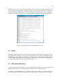
This obvious problem with this method is the fact that as the number of nodes grows it becomes
more and more infeasible to manually connect to a domain and view its output manually. The
description as to how this was overcome is described in Section 9.1.1 however here it is in brief. A
18
19
modified Java program developed for XenoTiny [18] was used to invoke the xm command, just as
the user would, for each domain. Using Java’s ability to execute shell commands, the output from
this was then collected and piped to a Java swing window and displayed to the user along with a
prefix of the relevant node’s id, Figure 4.1 shows the debug statements being caught in Domain0.
Figure 4.1: Debug Statements Caught in the Java Console
4.2
LEDs
The LEDs, light emitting diodes, are physical devices that would emit light on the physical mote
depending on the operations of the mote and its programming. Due to the software nature of this
emulation there was no physical representation of the leds and as a result these are represented via
a textual output. The LEDs are used in exactly the same way however this call simply outputs
messages via the debug output as described in Section 4.1.
4.3
Microcontroller Sleep
As previously mentioned in Section 1.1.1, motes make use of the ability to sleep during periods of
inactivity and by doing so can dramatically increase the duration of their battery life.
In Contiki on the MSP430 there is no specific module that provided the sleep functionality and
instead sleeping is controlled via hardware macros that are used to set hardware control registers.
20
The MSP430 provides five different sleeping options ranging from turning off the cpu to turning off
the cpu as well as all clocks.
A point of note is that these sleep directives differ from the normal sleep commands used in high
level languages in that no duration is passed for when the desired sleep should finish. Instead the
model is that the directive is invoked and the sleep is ended by an interrupt signal; during this time
no work is done.
In Contiki these macros are most notably invoked once the scheduler has completed all outstanding
work for the given time period.
In the Xen emulation, exactly the same logic was used in deciding where the placing of the sleep directives should be placed. In the actual implementation of the sleep calls a function, block domain(),
is used that effectively suspends the domain for a specified timeout value. In order to block for a
sufficient amount of time so that the domain is reawakened by an interrupt the FOREVER value is
used from time.h which is the equivalent of blocking for hundreds of years.
The semantics of the Xen blocking hypercall being used at the heart of the block domain() function
allows for any Xen interrupts to remove the domain from a blocked state and return it to being in
a runnable state as well as notifying the domain of the interrupt. In the case of Contiki this would
then allow for the continuation of the scheduler and consequently the continuation of the application
whilst conserving battery power or, in the case of Xen, the scheduler credit [2].
4.4
Timers
This section discusses the implementation of the emulated Xen version of the MSP430’s hardware
timers. Section 4.4.1 will be exploring the timer requirements of Contiki which will be followed by
how these are met by the MSP430 in Section 4.4.2. Section 4.4.3 will then explain the solution to
the timer problem and the implementation.
4.4.1
Contiki Timers
Within Contiki there are two main timers: the clock and the rtimer. The clock is the main periodic
1 second timer that is used to regulate the Contiki system, ie the protothread scheduler. In addition
to this, there is the rtimer. This timer has millisecond granularity and is not intrinsically a periodic
one as it is more to service the ad hoc needs of the system, for example the sleep periods of the
radio transceiver.
4.4.2
MSP430 Timers
The T-Mote sky platform provides the timing capabilities that are required in the above section via
the timers that are provided by its microcontroller: the MSP430.
The MSP430 platform provides two timers known as TimerA and TimerB. TimerA is a 16 bit timer
and is configured by user software. TimerB is almost identical to TimerA with the main exception,
21
with relevance to this project, being that it can also be set to be a 8, 10, 12 or 16 bit timer [15]. Each
of these timers can be connected to a different clock but for the T-Mote sky this is selected as the
32KHz clock [15].
4.4.3
Xen Timers
Xen provides the ability to schedule timer interrupts via the HYPERVISOR set timer op() hypercall. This hypercall schedules a one shot timer (in nanoseconds) with the Xen hypervisor. Xen then
fires an interrupt on one of the interrupt channels, which are assigned or “bound” when the domain
boots, to notify the domain that the timer has completed. There are two things to note about Xen
timers. The first thing is that only one outstanding timer may be registered with Xen at any one
time and the second is that these outstanding timers are known as events and shall henceforth be
referred to as such.
As previously mentioned in Section 2.2.2 Contiki has a very modular structure. As a result of
this the hardware specific implementations were isolated from the system, this being the case the
insertion of timing via Xen was made more manageable. However there were two main problems:
the need to convert between nano and milliseconds for the hypercall and the fact that only one
outstanding timer request may be present, yet there are two timers.
4.4.4
Timer A
The following details the exact hardware settings and manipulation of TimerA.
Hardware
TimerA is able to generate hardware interrupts in one of two ways: one when a “compare” value is
reached, and one by counting from zero to the compare value and back again in a loop(the interrupt
occurring at each boundary). The “compare” value is kept in the TACCR0 register and takes a
value of either 0xFFFF, if the timer is placed in continuous mode, or user specified using software.
There is a SCCI register that synchronises input to the TACCRx registers, of which there are three.
Another register, TAR, is incremented at every clock tick and it is this register that is compared
against TACCR0 to decide when the interrupt should be generated. When the interrupt is generated
a value associated with the specific interrupt, compare or overflow, is set within the TAIV register.
In this case the value in TAIV is added to the program counter (PC) which jumps to the appropriate
interrupt handler within the interrupt handler table. Figure 4.2 shows a simplified state diagram of
the compare mode.
22
Figure 4.2: Simplified Capture State Diagram
There is also the option with TimerA to increment TAR after a number of ticks rather than after
each consecutive clock fire. For the T-Mote this is set to 8 producing an effective clock frequency
of 4KHz from the 32KHz clock, this is converted to a 1 second timer in software by setting TACCR0
to 4,000. Should a value greater than one second be required, then this was achieved via software
constructs that would rely on multiples of the software timer interrupts, a four second delay is
achieved by waiting for four timer interrupts.
Xen: Timer A
Given that TimerA’s behaviour had been deciphered the next step was where exactly the emulated
logic using Xen should go. As said previously the modularity of Contiki highly points towards
rewriting the driver components of Contiki for the given Xen cpu, as discussed in Section 3.2.
In the modification of this driver code it was important to maintain the function prototypes and to
only modify the internals to use either hypercalls or changes to the way the variables within clock.c
are manipulated. For example only registering an event with Xen when initialising as opposed to
setting registers.
4.4.5
Timer B
In the case of TimerB much of what has been said about TimerA is identical and as a result this
shall not be repeated. Below is a list of the hardware differences between TimerB and TimerA:
• TimerB may be a 8, 10, 12 or 16 bit register
• The capture and control registers are double buffered and can be grouped
• There is no equivalent SCCI bit to synchronize access to the capture and control registers
• All outputs can be placed into a high impedance state
For this project the most notable difference between the timers was that TimerB provided millisecond granularity.
23
4.4.6
Xen Timer
Considering that TimerA and TimerB had to run in a concurrent fashion there was a clear need to
manage access to the hypervisor, considering the restriction of only one outstanding timer event
request at any time. It was also necessary to delegate the timer events returning from Xen to the
relevant timer which requested it.
In answer to this, the XenTimer component was created which was tasked with scheduling interrupts with the hypervisor for each timer and maintain a collection of requests when there was more
than one outstanding at any time. The component was also responsible for notifying the relevant
timer that its timer event had fired. Figure 4.3 shows the Xen Timer model.
Figure 4.3: The XenoContiki Timer Model
4.5
IDS
Each node within a wireless sensor network that runs Contiki has a unique identifier, a node number.
This node id was used for many purposes such as in the sender field of packets to be sent and
conversely to be used to filter incoming packets, to determine if they were or were not for the
particular node. The node id may also in some cases be used as the seed for, in the case of Contiki,
rand() ; the random number generator function.
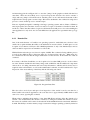
For real nodes the node id may be retrieved from its EPROM (flash memory) during boot however
this presented a challenge for the simulation as the EPROM was not emulated however, this was
overcome via the use of the Xen Store.
24
4.5.1
Xen Store
The Xen Store is a feature of Xen that is primarily designed to facilitate shared memory between
domains for configuration and status information. The Xen Store is a Unix style directory structure
beginning with the / or ’root’ and consists of three main directories [22]:
• /vm - stores configuration information about domain
• /local/domain - stores information about the domain on the local node
• /tool - stores information for the various tools
The Xen Store is accessed via a number of commands from Domain0. Each of these commands are
prefixed with xenstore- and include: read, write, rm and list.
Each domain may access its own space within the Xen Store and Domain0 has the ability to access
the Xen Store in its entirety. Due to this fact it was decided that the Xen Store would be used to pass
certain start of day information to domains, such as the above mentioned node id, discussed later in
Chapter 5. This was achieved by placing the CONTIKI NODE ID in the Xen Store by Domain0 at
the domain’s creation and then accessed and used by the domain during its boot phase.
In particular a domain accesses the Xen Store by way of the xenbus read() function which returns a
string. This string is then parsed to generate the associated integer, node id. This process was added
in place of the existing Contiki node id restore() function and seamlessly fits into the existing
Contiki code.
Chapter 5
Radio Communications
So far the creation of a XenoContiki domain has been discussed in detail and as such there is now
an understanding of the emulation of a Contiki node. The next step was to allow a medium through
which domain intercommunication can be achieved and also a way to allows node’s to use this
medium. As described in Section 1.1.1, one of the most important features of a wireless sensor
network is the ability of a mote to use its radio to communicate with other motes to achieve the
complex functionality required of a wireless sensor network.
This chapter will discuss the radio hardware of the T-Mote sky which will be followed by a discussion of the replacement radio components that will be used within XenoContiki and culminating
with the “ether” that will allow the propagation of the radio packets.
5.1
T-Mote Radio
The following section will discuss the T-Mote’s radio component, the CC2420, and mention the
software used to control it, in particular the Contiki Rime communications stack [9].
Hardware Components
The radio component of the T-Mote sky mote is the Texas Instruments CC2420 [14]. This component is connected to the microcontroller via a number of pins, as can be seen from Figure 5.1.
25
26
Figure 5.1: Microcontroller-Radio Hardware Interface
The pins are split into two groups, the first of which are used during transmission and reception:
• FIFO - Used to indicate data in the receiver buffer
• FIFOP - Used to indicate that the receive buffer had reached its pre-programmed threshold
• CCA - Clear Channel Assessment
• SDF - Start Frame Delimiter, indicating that there is an incoming frame, or that one is being
sent (depending on the radio’s mode)
The second group are used to facilitate data transfer between the radio and microcontroller:
• CSn - Chip select, enable or disable communicates with the chip
• SI - Serial data into the radio
• SO - Serial data out from the radio
• SCLK - The clock from the microcontroller
For the FIFOP or SDF pins, the microcontroller is notified of these events by interrupts which are in
turn handled by software components in Contiki. This software can also manipulate these hardware
pins, such as in the case of CSn, whereas the FIFO and CCA pins must be explicitly checked.
Similar to TinyOS, time stamping occurs when a packet is received however it is the software
interrupt that simply records the time via TimerB rather than generating an explicit capture when
the hardware interrupt occurs.
The second group of pins are linked to the SPI bus and it is this bus that is used to control the
movement of data between the cc2420 and the microcontroller. This bus is primarily manipulated
by software and in Contiki via a set of pre-processor macros.
27
As in the previous timer section, Chapter 4, all of the hardware access are abstracted away into
modules within Contiki, thus allowing decoupling and resulting in the radio management being
quite distributed depending on what level of interaction is required. The main software module, for
the purposes of this project, is the simple-cc2420.c which will be discussed below.
Software Components
Within Contiki, access and manipulation of the radio is granted via the simple-cc2420.c module.
The primary functions of this component are to send and receive packets as well as to activate and
deactivate the radio chip. In order to do this it uses a combination of the pre-processor macros
provided to arbitrate access to the SPI bus as well as using some of the higher level calls to TimerB
provided by other modules.
In order to send a packet via the radio it is loaded into the radio transmission buffer, which can
only hold one packet at a time, to which the preamble and the frame check sequence is then added
in hardware. This loading of the buffer may only be completed after waiting for the previous
transmission to complete. A strobe macro is invoked which sets the appropriate pins in hardware
on the radio and thus commencing the radio transmission. There are usually two options when
sending: one of which takes advantage of the CCA pin and sending only if the channel is clear and
the other sending regardless, in Contiki it is the latter. The return value is either 0 upon success or
an error code, dictating a transmission error.
In order to receive a packet the radio chip generates an interrupt and the handler for this interrupt
in turn requests that the Contiki protothread responsible for receiving packets be polled. Once
successfully polled the thread first checks the length of the received packet using the SPI macros.
If the packet is of the wrong size then the radio buffer is cleared, else the packet is read into a
software variable via the SPI bus. At this point the checksum is evaluated and if correct the receiver
strength signal value of the channel from the packet suffix is noted and the data is passed on up
to the higher layers minus the link layer suffix information. If the checksum is incorrect then the
packet is discarded.
There is also a MAC(Media Access Control) module at the lowest layer of the Rime stack, which
provides the CSMA(carrier sense multiple access) guarantees. If a node should wish to send a
packet, the medium of transmission is first checked to see if it is in use and if so the node will back
of for a random amount of time and then retry. This fulfils the collision avoidance requirement of
CSMA/CA. Considering that a node cannot send and receive at the same time, collision detection
is not possible on the T-Motes hardware. As a result this normally leads to the need for ACK
packets. The ack or acknowledgement packets serve as guarantees that packets have been received
successfully and if the sending node were not to receive an ack then the initial packet would be
retransmitted after a random time. In Contiki this is not the case and the auto ack feature of the
radio hardware is turned off. To compensate for this the ack packets are instead handled in higher
software levels within the Rime stack.
These two modules allow Contiki basic radio communications. Upon this platform sits the Rime
stack, which offers a rich selection of communication primitives such as reliable unicast transmission, mesh network transmission, trickle (gossip) transmission as well anonymous best effort local
broadcast.
28
5.1.1
Netsim Radio
Within Netsim, radio simulation is carried out external to the implementation of a node which, as
previously mentioned, is an individual process within an operating system. The radio component
is replaced by a custom “ethernode” radio implementation that is responsible for both transmission
and reception of packets. These packets are sent into an ether component which is responsible for
the delivery, or not, of these packets.
This particular implementation is, as Section 5.3.3 will enlighten, remarkably similar in concept as
to how the network model operates. This has the advantage of being comparable to the final network
model for testing purposes as well as being a slightly simpler analogy with the main network model
of this project.
5.2
Xen Radio
At this point in the design it was decided that the problem should be split into two section: the
emulation of the radio with the XenoContiki platform and the transmission medium through which
packets will be sent. This section will deal with the first point. In relation to the transmission
medium it was decided that the Java network model which was created for XenoTiny would be
sufficient as well as being perfectly compatible with XenoContiki [18]. It would also allow concentration on other elements of the project as well as it already being reliably tested. This said the
mechanics of it will still be covered briefly to give a general overview in Section 5.3.3.
5.2.1
Radio Emulation
Again thanks to the modular structure of Contiki the decision involved in choosing which elements
to replace was made somewhat simpler.
29
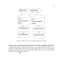
Figure 5.2: Baisc Layout of the Contiki Communications Stack
Figure 5.2 shows a somewhat simplified structure of the networking stack within Contiki however
it illustrates quite clearly that the only communications to or from the cc2420 radio component are
via the Rime stack and upon examination this translates to the simple-cc2420.c driver module. Considering the complexity that would be involved in emulating the behaviour of each of the individual
SPI macros and their effects it was instead decided to simply replace the entire simple-cc2420.c
module with that of xen radio.c, Figure 5.3.
30
Figure 5.3: Modified Contiki Communications with Xen Radio
5.2.2
Control
It was the duty of the simple-cc2420.c module to ensure that the radio chip was in a correct state
to perform any desired actions, not least of which included turning the radio on and off to conserve
battery power. Within the Xen radio this is emulated by still requiring these commands to be called
however they are simply replaced setting a state field to true or false depending on the whether the
device is being turned on or off. There are also implemented checks to prevent the radio being
used if it is an off state. Previously it was the task of this module to arbitrate access to the SPI
bus however, as previously mentioned, this has not been included in the Xen emulation. It should
also be noted at this point that the Xen Radio component exports a struct of function pointers that
encapsulate the functionality of the radio component, Xen or otherwise:
• Send - Used to send a packet
• Read - Used to read a received packet
• Set Reciever - Used to set the function to be notified of an incoming packet
• On - Used to turn the radio on
• Off - Used to turn the radio off
The On and Off components refer to the functionality previously discussed, with the functionality
of send and receive being the following topics of discussion.
31
5.2.3
Transmission
Having now considered how the emulation of the control of the radio is handled, the next step
is to consider the emulation of transmissions. In the design of this stage the primary sources of
information were the CC2420’s data sheet as well as the existing software within Contiki, a similar
set of techniques to those used in the timer design as discussed in Section 4.4.
As the transmission is, for all intents and purposes, a self contained function, it would seem logical
to express its design in the stages of the function and how it is emulated.
Previously before the packet could be moved to the radio component it was necessary to wait for
the completion of the previous transmission to complete; this was not explicitly waited on so as to
increase performance and conserve battery power. In the emulation this is achieved via the use of
locks that will block access to the calling function until the previous call to transmit has released
the lock, thus ensuring that any packet being sent is not corrupted.
After access had been granted to the radio chip the length of the data being transmitted was then
quantified to ensure that no buffer overflow had occurred; if this was the case then an error value
was returned to the calling function. This behaviour was fairly simple to emulate and is done via a
simple check to ensure that the data to be sent is not longer than the maximum buffer size of one
hundred and twenty eight bytes and if this is the case an error value is returned, just as before.
It is at this point in the hardware that the clear channel assist pin on the radio would be activated
to ensure that the channel is clear to send however in the Xen implementation the support for this
has not yet been implemented and will be mentioned in the future work section. At this point the
packet is sent regardless of whether or not other nodes are transmitting.
Also at this point the CRC checksum would normally be calculated in hardware but now must be
done in software. Luckily an implementation of the hardware calculation was available in another
module within Contiki (crc16.c). The checksum was calculated and appended onto the last two
bytes of the packet which was then sent to Domain0 for redistribution.
The final point to mention is the hardware preamble. This preamble is added by the radio hardware
and is used to let the clocks synchronise and allows data in the packet to be read correctly. Upon
receipt of such a packet the hardware would remove this preamble and place the payload into a
buffer ready to be read by software. In this project the preamble is not prepended to the packet
before transmission as it would by removed upon receipt by the receiver’s hardware and so has no
relevance for this simulator as it is the same clock for all domains.
5.2.4
Reception
When receiving a packet, the Xen Radio component is only able to accommodate one 128 byte
packet at a time, this was to emulate the existing functionality that is used within the Contiki implementation and the hardware of the CC2420. As in hardware any incoming frame is copied into
the buffer, if there is sufficient space. At this point a hardware interrupt would be generated on SDF
notifying of the incoming packet where as in the Xen Radio this is handled by a handler function
which is registered with Xen. Notification of incoming packets is done via Xen events which call
this function, however this will be discussed more in Section 5.3.3.
32
The generated interrupt will then request the protothread responsible for receiving packets be polled
so that it may process the incoming packet as well as noting the time and setting a flag to say that
the radio is currently processing a packet. This protothread is used to request that the function,
which was registered during the Xen Radio initialisation via the set receiver function, be informed
of the incoming packet. It is the assumption of Contiki and XenoContiki that this function will
either directly or indirectly call the read function in order to retrieve the received packet from the
buffer. If there has been no function set then the received packet is simply cleared to make space
for the next, in the Xen Radio this is done by setting the flag previously mentioned to indicate that
the radio may once again accept packets.
The read function itself has the task of either passing the correctly validated packet to the calling
function or returning an error value indicating that the packet was malformed somehow. There are
two possible causes of error: a packet is of the wrong size or the Frame Check Sequence (FCS) is
incorrect.
Whether or not a packet is deemed to be of the wrong size is determined by a minimum size, the
FCS of 2 bytes, or if the packet exceeds the size of the buffer provided by the calling function.
Once the validity of a packet length has been determined the next step is to validate the FCS. This
is done by recalculating the checksum from the packet, not including the two byte checksum at
the end, and comparing it to the checksum included within the packet. Once calculated the two
checksum bytes are then replaced with the following:
• Received Signal Strength Indicator (RSSI), one byte
• FCS valid/invalid, one bit
• Link Quality Indicator (LQI), seven bits
In the current implementation the RSSI and LQI are set to the maximum possible values. This
is because their modification would need to be dictated by the radio network and at present this
functionality is not implemented.
Once the packet has been deemed valid it is then copied into the buffer provided by the calling
function and the length of the received packet returned as well as setting the flag to indicate that the
radio may again accept packets and releasing the lock protecting the radio component.
As an aside, the CC2420 has the option to send automatic acknowledgement frames via the hardware however Contiki has disabled this option in favour of using higher software components to
handle any required acknowledgments.
5.3
Simulated Radio Network
Having covered the emulation of the radio component there is now sufficient detail to completely
emulate Contiki with a domain over Xen or in other words XenoContiki. However there is still no
medium that would allow each XenoContiki node to communicate which is where the Java radio
medium enters. As mentioned previously the Java medium, or network model, is a modified version
of the one created for XenoTiny and as a result this section is derived from [18] Section 5.4 and will
only highlight the important aspects.
33
5.3.1
Network Requirements
In a real world network, communication between motes is often hampered by packet loss, radio
noise and collisions. In addition to this the power of a mote’s radio transmitter is limited and,
consequently, as a packet moves beyond the maximum transmission range then the packet will
exhibit increased bit error and often loss.
In an accurate simulator it is possible and indeed necessary to implement such a radio model that
will simulate the above effects of a desired local and set of circumstances. Cooja, and to a lesser
extent Netsim, is capable of simulating these conditions. The Java medium (JM) does provided the
ability to include such a complicated radio model however it was not the goal of either XenoTiny
or this project to implement such a sophisticated radio model, consequently a perfect radio model
is used in both cases.
5.3.2
Network Design
The general design of the network is based around the idea of a central hub. Each node in the network transmits their packets to this central hub which then in turn relays the appropriate messages
to the appropriate nodes; what is deemed appropriate is dependent on the radio model in use.
This means that modifications to the network can be carried out in a single place, thus easing the
task of the developer. The main advantage however, is that the topology, during the running of a
simulation, is in one place and as a result creation, deletion and the movement of a node’s geographical location can be controlled from a single location. The fact that all inter-domain communication
must pass through Domain0, as described in Section 2.6, was also a factor in this decision.
5.3.3
Network Mechanics
The following will explain how exactly packets are transferred between XenoContiki nodes via the
JM. In detail it will describe how packets are carried from one node’s Xen Radio component via the
network in Domain0 and then relayed to the Xen Radio component in another node.
Xen Implementation
Within Xen there are two separate methods for inter-domain communication: grant tables and the
Xen Store.
The Xen Store, Section 4.5.1, could be used to transfer packets between domains however the
related documentation suggest that the Xen Store is unsuitable for large data transfers. While the
size of a packet could not be considered a large data transfer in the given context, the sheer potential
volume of packets that could be sent may cause the Xen Store to act as a bottle neck. It was instead
decided to leave this to passing start of day information instead.
The alternative to the Xen Store was to use grant tables. These are shared areas of memory that
allow domains to transfer (potentially large) amounts of data at a fast pace. A domain is notified of
34
an incoming transfer via events, similar to those described in Section 4.4.3.
Mini-Os provided a frontend network interface using the grant table transfer method. This presented a tidy solution as now an Ethernet frame containing the radio frame could be used instead
of manually using the shared memory and events. Within Domain0 these Ethernet frames could
be handled in the normal manner within its network layers and eventually passed to the application
layer, JM.
Protocol Choice
Ethernet frames themselves are not usually used within user applications and as such a higher
level protocol had to be chosen. The two choices were between TCP and UDP, as they are the
predominant IP protocols in use within Domain0, XenoLinux.
TCP was considered due to the reliable transfer of data that it provides however, this was not chosen
because of the unpredictable delays during transmission which could affect the simulation of radio
traffic in unexpected ways.
Unlike TCP, UDP does not have this problem as the only addition to the underlying IP is that of
ports. The unreliability of UDP is not an obstacle within XenoTiny as all data transmission takes
place within a single machine and no external network is ever used; thus the possibility of packet
loss is almost impossible. The only downside was the possibility of a bottleneck within the network
stack of Domain0, however as this runs at a higher priority than all other domains, packets should
be dealt with in a timely manner and not discarded.
Xen Ether Componenets
As previously mentioned Mini-Os has the capability to send Ethernet frames to Domain0 using its
imaginatively named frontend network interface component: Netfront. Although this functionality
existed there was no ability to actually create these Ethernet frames of IP packets, it is assumed that
as Xen was designed to support large operating systems the networking stacks within them would be
used to form these. As a result this functionality was added in the form of the xen ether functions
component, see Figure 5.3.
In a similar concept, the physical CC2420 radio would convert the Contiki packets passed to it into
a form appropriate for the medium of transmission, so too does the xen ether functions component.
In particular this component is responsible for wrapping the Contiki packet within UDP, IP and Ethernet headers, see Figure 5.4, which are then transmitted via the domain’s virtual interface towards
Domain0. This information is stored within an ethernet frame t which is a C struct containing the
header information for the UDP and IP packet headers as well as the Contiki radio frame itself.
Figure 5.4: The XenoContiki Network Frame Format
35
Fig 5.4 shows the different wrappings around the basic Contiki radio frame. Within each header a
number of constants are also included. Within the UDP header, (2), the destination and source ports
are included. Within the IP header, (3), the source and destination IP addresses are included and
in the Ethernet header, (4), the source and destination MAC addresses are included. These values
are all per-domain constants which are calculated before a domain is created. The domain is able
to access these values as they are passed as start of day information which is then accessed during
initialisation of the Xen Radio.
This complete frame is then serialised into a byte array and sent to Domain0.
Figure 5.5: The XenoTiny/XenoContiki Network Model [18]
Upon receipt of a frame from Domain0, as notified via a Xen incoming frame event, an ethernet frame t is constructed and populated from the incoming flat byte array. The headers within the
new frame are then compared against the values for the given domain. For example, if the destination MAC and IP addresses as well the UDP destination port are not exactly the same as those
for the given node then the frame is discarded. These checks are required as within Domain0 the
packets that are being received are transmitted along a single Ethernet bridge (“xenbr0”) to which
all domain’s virtual interfaces are connected to and as a result a domain will receive packets not
destined for it. So as to retain some performance each check is only performed if and only if the
previous was valid in the order of MAC, IP and UDP. As an aside, it is the case that if one check is
correct they all are.
These checks were also required as the destination mac address for packets being sent from nodes
was set to be the Ethernet broadcast address. As mentioned previously in Section 2.6 an Ethernet
bridge is used in Domain0 to connect all of the vifs, which in turn allows different domains to
communicate with each other. Unfortunately, a problem with this Ethernet bridge did not let these
incoming packets from nodes be successfully passed to the Domain0 vif. Obviously this would
prevent the network simulation working at all and so to ensure that the packets were received by
Domain0 the broadcast address was used.
36
Upon successful completion of all checks, the packet is then stored in a temporary buffer, analogous
to the physical buffer within the CC2420, after which the radio interrupt is generated and the packet
is then handled by the Xen Radio.
Chapter 6
Insense Runtime and XenoContiki
In Section 1.2 it was mentioned that one of the aims of this project was to successfully run Insense
applications within XenoContiki nodes and simulate their network functionality. This section shall
discuss the modifications required to the Insense source and build process in order to achieve this.
6.1
Insense Build Process
As previously discussed Insense is a language in its own right with its relation to Contiki being that
Insense programs are compiled into Contiki applications. This is an increasing common method
for the implementation of new languages as the security of an existing working language removes
the need for complicated code generation techniques within modern compilers allowing more time
to be spent on other aspects of a languages development and gives the benefits of the effective
optimising compilers.
After the compilation to Contiki, via a Java based compiler, the result is a directory containing all
of the necessary files to be compiled into the desired Contiki application. In the case of the Hello
World example, simply outputting “Hello World” to the screen, the generated files consist of a make
file and three C source files. These files include a main to coordinate the application, the actual file
containing the hello world program and an error handling module.
All of the code within these files is designed to work with Contiki including the makefile which
behaves just as any other Contiki application makefile, by compiling all relevant core files as well
as the application and linking them together to form the binary. It is invoked just as previously
discussed with the command make TARGET=(platform) and expects to be in the examples folder
within the Contiki directory structure.
The main difference between Insense and other applications for Contiki is that an Insense program
expects to be compiled against a separate runtime library. This is done in order to support the fundamental features of the Insense language, such as the half channels, within the Contiki environment.
The library itself is a collection of files that have been coded for interaction with Contiki and allow
the extra functionality required by the Insense-Contiki application.
The compilation process itself requires that an environment variable DAL RUNTIME be specified
37
38
and that this variable point to the location where the runtime is stored. The build process actually
compiles the library into an archive file, similar to the Contiki archive file containing the core files
in object format. These archive files are then linked with the object files for the application in order
to produce the final binary image.
6.2
Insense Modifications
The modification of the build process can be split into three main sections consisting of the modification to the Insense-Contiki build process; the modifications required to the runtime library and
the modifications to the existing XenoContiki build process. There is also a final section detailing
minor additions required to Mini-Os.
6.2.1
Insense Build Modifications
In a similar manner to the changes that were made to the Contiki build process, described in Chapter
3, it was necessary to point the compilation process toward the libraries contained within Mini-Os
and not the standard libraries in order to ensure that the library calls were compatible with Xen.
As before this was done with the compiler flags -nostdlib and -nodefaultlibs to ensure that the
standard libraries were not used as well as specifiying the path the the Mini-Os libraries with the -I
flag. It was also necessary to prevent the Insense-Contiki build process from linking together the
archive files and application files as this had to be done later on in the XenoContiki build process
so as to create the domain image.
6.2.2
Insense Runtime Modifications
It was expected, before actually attempting this section of the project, that the compilation of
Insense over XenoContiki should have been fairly unproblematic, unfortunately this assumption
turned out to be incorrect.
As for the main changes to the build processes discussed above, similar measure were required in
altering the makefile for the runtime. In particular a change that was required was the removal of the
malloc component. This was necessary as the methodology used in this function was incompatible
with Contiki; instead the malloc component of Mini-Os is used.
Unfortunately a mismatch in the version of Contiki expected and the one used in this project was
present and as a result a number of stop-gap measures were made to the Contiki function calls in
order to make the runtime compatible. This could simply be fixed by modifying a more modern
version of Contiki into XenoContiki. This was not done in this project as at the time of discovering
this problem not enough time was left to take a more recent version of the Contiki source and
modify it.
39
6.2.3
XenoContiki Build Modifications
The modifications required to the XenoContiki build process were fairly simple. All that had to be
included was the Insense archive file containing the runtime object files during the make-ing of the
system. Normally the make file generated by Insense ensured that this was included in the linking
process however as the linking was not carried out until the linking with Mini-Os this modification
was necessary.
6.2.4
Mini-Os Modifications
During the linking process with Mini-Os the compiler noted a number of errors related to the lack
of certain functions and as a result did not complete linking. This was because these particular
functions were included in the standard libraries however as Mini-Os was not a fully implemented
operating system, as previously mentioned, not all expected functionality was present.
To solve this problem two options presented themselves: include implementations for the desired
functionality or remove the requirement from Insense. As the latter option would restrict the ability
of Insense it was decided to implement the functionality. Atoi was an example of one of the missing
functions which was successfully implemented and can now be found within the Mini-Os libraries.
Chapter 7
Topology Managment
As mentioned previously the Topology file is used to hold the locations of the nodes within the
network however it is also used to control the addition, modification and deletion of nodes to the
network and because of this it is able to compile, create and destroy Xen domains.
This section shall detail how to manipulate the network described in Section 5.3 mainly via a collection of tools that automate the build, creation and destruction process of the domains. There will
be slightly more detail in the following than the previous section as some fundamental aspects of
the network required changes to be compatible with XenoContiki. As the Java medium was used
from XenoTiny, and this section details its use, the following is a derivation of [18] Section 6.1.
7.0.5
Scripts
In order to build a XenoContiki domain there are a number of steps, which are quite mundane to
perform by hand, Section 3.2. The three initial stages consist of running make TARGET=xen in
the desired application directory, then running the make command again in the Mini-Os directory,
this time with the previous build object included in this build process and then finally creating the
Xen domain using the privileged xm create command.
Once the domain has been created several per-domain settings must be modified for the next domain. The domain-config file must be updated with the next unique name for the next domain to be
created, as required by Xen. It is also necessary to enter the relevant data into the Xen Store, such
as the domain’s IP address and other start of day constants, so that the domain will be able to access
these constants that it would require during runtime. To ensure that the Domain0 network model
will be able to communicate to each of the individual nodes, via their interfaces, it is also necessary
to call the arp command.
The simplest way to automate the above processes is by way of shell scripts. By doing this the build
process can be simplified down into a single call: a createDomain script. By simply specifying
the location of the application that is to be run by the node, this script is able to infer the directory
in which the make TARGET=xen command should be run, modify the Mini-Os build process to
include the freshly created XenoContiki object file as well as build it and complete all of the Xen
Store and arp admin as specified previously.
40
41
The complete list of scripts required for automation of this project is listed below:
• Domain building and running
• Domain destruction
• Destruction of all running domains (used in cleanup)
• Pausing and unpausing a domain
• Viewing a domains emergency console (used to display a node output)
It is these scripts that allow either the user to manually assert control over a XenoContiki node or,
more importantly, allow the JM to automatically do this.
7.0.6
Domain ID
Within Xen each domain is assigned a unique identifier which can never be reassigned, even after
a domain is destroyed. This unique identifier is simply a number starting from 1, 0 is always
used for Domain0, which simply increments with each new domain. The reason that this is worth
mentioning is that the numbering convention that is used with the Contiki simulator is different.
Contiki nodes are given different unique ids which are passed to them as start of day information
and are chosen by the user as an option to one of the aforementioned scripts. These numberings
are unlikely to match the xm command from Xen, which is able to accept both Xen unique id
and domain name when selecting a domain to execute a command upon. This independent node
identification scheme also means that a node’s IP and mac address, which are based upon the Contiki
identifier, can be calculated from this id without the need for look up tables.
The name of a domain is simply of the format <DOMAIN PREFIX>(Contiki node id), eg Contiki1.
By formatting in this way it allows for all domains running Contiki to be identified, this is useful
when running the script to destroy or list all Contiki domains, while not including other domains
such as Domain0.
7.0.7
Domain Control Methods
At present the model of the system is to use a Java program to run the scripts mentioned above
and by doing this a number of useful feature are available. First of which is the object oriented
programming style that Java presents which is useful for future additions to the system as well as
extensive libraries and type safety. Also by using this Java program it means that a user is able to
present the program with a topology file which would be parsed in order to generate the particular
topology to be emulated [18].
At present there is a minimal GUI implementation that does provide the necessary basic functionality. It allows all debug output from the nodes to be displayed in a console, this process of outputting
to the console is discussed in Section 4.1. These is also a console that allows the user to manually
modify the topology as well as add or remove nodes. This particular area leaves much room for
future work but will be discussed later in Section 9.1.3.
42
7.0.8
Topology Creation
Within the simulator it is the topology that is responsible for holding the positions of the node and it
is to this that nodes may be added, moved or removed to effect changes in the actual network model
and in turn the running Xen domains.
Each line of a topology file represents a node’s position in the network and takes the following
format:
• Node Id
• Latitude (+/-, degrees minutes, seconds)
• Longitude (+/-, degrees minutes, seconds)
• Altitude (metres)
• Node Application
The decision to use a real world coordinate system was made to provide a way to provide a direct
mapping between simulation and the real world deployment. This coupled with an accurate radio
model would ensure the correct operation of the nodes in that given deployment. The inclusion of
the application to be run on the given node allows for a heterogeneous network of nodes running
different applications. This feature is part of Cooja however not part of Netsim.
After the topology has been parsed the nodes are then started, as discussed above, and put into a
paused state. The starting process can take some time, see Section 8.4.2, and this is done so as to
prevent some nodes getting too far ahead of others. Once the final node has been created the nodes
are then unpaused in as quick succession as possible. Inevitably there will be some delay as nodes
must be started sequentially, however best effort is made to ensure that this is kept to a minimum.
The final step in the simulation of the radio network is the ability to determine the distance between
nodes and, knowing the sending range of node, decide whether or not a packet should be delivered
to them. As the distances are in degrees, minutes and seconds this was converted into meters using
OpenMap, an open-source package. Unfortunately OpenMap does not handle three dimensional
points and, as the topology file can include altitude as well as latitude and longitude, some additional
calculation was required. Firstly the distance along the ground, g, was calculated using the features
that OpenMap provides. Secondly the difference in altitude between the two nodes, a, was taken
using these two values in the Figure 7.1 a right angled triangle can be constructed with the distance
between the two nodes being the hypotenuse[17].
43
Figure 7.1: distance calculation, d =
7.0.9
p
(g)2 + (a)2
Modifying A Topology
In previous sections the notion of modifying a topology has been alluded to and shall now be
expanded upon. The network model is capable of changing the topology in various ways. Nodes
may be added to simulate new nodes being turned on within the topology or removed to simulate a
node being turned off due to the battery running out or being destroyed, as may be the case in a real
physical environment. It is also possible to move a node to a different location which in a real world
situation may be caused by changing environmental conditions or perhaps even a curious fox.
These changes may be effected in the network by a series of simple commands with the desired
parameters entered into the GUI console, a full listing of these can be found in the user manual in
the appendix. An example of the input can be seen in Figure 7.2.
44
Figure 7.2: Topology Control
Chapter 8
Evaluation
Having now fully covered the creation, emulation and simulation of a network simulator of XenoContiki nodes, the next step is to prove its correctness and show its performance. The following
section will be mainly in two sections discussing the correctness of the system and how it was
proved as well as the performance of the system in terms of its emulated accuracy and the performance of aspects of the simulation.
8.1
Component Correctness
Throughout the project, standard component or module testing was carried out. For example before
the timer component was included it was tested in isolation using a test harness to ensure that is
was behaving correctly.
Once this testing was complete, the components were then included in the main body of code.
Testing was again carried out to ensure that the correct behaviour of each component was still
present. Naturally this highlighted some errors that were not caught in the previous bout of testing,
which were fixed.
8.2
Simulator Correctness
In keeping with the analogy that porting a system to Xen is similar to porting a system to a new
hardware, the next step was to ensure the correctness of the simulator by ensuring that the test
programs provided with Contiki worked correctly. The section describes the test programs used.
In particular those example programs contained within the rime folder mainly because this would
allow testing of the Rime Communications Stack[9] within the simulation.
45
46
8.2.1
Hello World
Arguably the most important initial test to any system, Hello World was the first to be tested. This
application simply tested that a domain output the string “Hello World” to the emergency console
at set periodic intervals. This output was done via the log message() function described in Section
4.1. This has the advantage of testing timers, console output and the modified XenoContiki kernel
as well as the system in general.
8.2.2
Test abc
This example simply broadcasts a packet into the network using the anonymous best-effort local
area broad-cast (abc) module within the rime stack. The packets that are sent contain the message
”hej”, the Swedish hey, which is then output via the log messgage function upon receipt by a node.
This was of equal importance, in a networking sense, to the above Hello World as it is one of the
primitives of the rime stack and shows that packets could be sent and received.
8.2.3
Test Polite
Test Polite is similar to Test ABC in that it also sends a packet to all neighbours however the
difference is that is if a node overhears the same message from another node it drops it own message.
This example uses the iPolite module in the rime stack which in turns uses the abc module. This test
is of importance as it shows that packets with sequence number can successfully be sent and used
as well as that the radio component can successfully send and receive properly formatted packets.
8.2.4
Test Trickle
Test trickle is used to test the Trickle (reliable single source flooding) module within the rime stack.
Once a button has been pressed on the node, it then floods the network with its “Hello World”
packet. A node will then display this message on debug output if it is the first time it has received
this message and then broadcast the packet out to its neighbours. Sequence numbers within the
packet are used to indicate if that particular packet has already been seen. The Trickle module uses
the Network Flooding (nf) module which in turn uses the iPolite module. Trickle is of note as it
shows that not only can packet be sent and received by the radio component but that it can now
retransmit packets on to other nodes and not just the original sender.
8.2.5
Test MeshRoute
The MeshRoute application tests the mesh module of the rime stack. After a button on a node was
pressed, that node would try and send a “Hej” packet to a desired node, for testing this was always
node 1. The routing table within the route discovery module was consulted and, in the initial case,
no route would be found. At this point the route discovery would flood the network with route
request packets via the nf module and also set a timer for a packet timeout value. All intermediate
nodes would note in their routing table either the sending node or the node who can relay a packet
47
to the sending node after which they would then use nf module to forward the request. When the
desired node eventually received the request it would send a route reply packet following the route
that was used to reach the recipient node in the first place. Finally, once the original sending node
had received the reply packet it would send the actual data packet back along newly discovered
route, provided the timeout had not expired.
In this test, as with all tests that required some user input, input was simulated by the use of timers,
to wait until the system was stable, and the nodes unique id, to select which node would be used to
press the button.
This test shows that the network is able to successfully send, receive and route packets to and from
nodes that are out of range.
8.2.6
XMac Component
In Section 5.1 the use of the mac layer is discussed and how it provides CSMA/CA. Within Contiki
there is a component which is responsible for this, xmac. This component provides the ready to
send (rts) and clear to send (cts) messages that allow protection against packets being lost due to
multiple transmissions within the transmission medium to a single node.
Unfortunately the version of Contiki taken at the beginning of this project contained an error within
this component and as such this features not currently present. This simulation is still able to
function and in the case of broadcast packets or when 1 to 1 communication between nodes occurs
the simulation is accurate. However, in the case of n to 1 communications accuracy can not be
guaranteed.
In order to ensure a fair comparison between XenoContiki and Netsim the xmac component within
Netsim was also disabled. Thus the issues faced by the XenoContiki would also be faced by Netsim.
In the latest version of Contiki, 2.2, the xmac component has been fixed and the next step for this
project would be to simply create XenoContiki 2.0 using Contiki 2.2 as its base.
8.3
AODV
One of the goals of this project was to implement an AODV application. The MeshRoute application discussed above is an implementation of AODV, although not the most sophisticated, and so it
was decided to use this instead of creating an implementation in either C or Insense.
The main reasons for the inclusion of the AODV application were two fold. Firstly, to show that it
was possible to simulate, i.e. that nodes, who could not directly transmit to each other, were able to
use intermediate nodes to provide a path through the network and that the network would support
this. Secondly, to show that the network could still cope as the size of the network scales.
Section 8.2.5 has discussed how the MeshRoute application works, thus proving the first point. The
second point of scalability is answered in the following sections and a comparison is made against
Netsim so as to give a sense of reference. For both Sections 8.3.1 and 8.3.2 the sending node was
48
always the top right of the network (n) and the receiving node was always the bottom left (1), i.e. the
path to be established was across the diagonal of the node configuration which was always square.
8.3.1
Discovery Time
Figure 8.1: MeshRoute discovery times
Figure 8.1 shows a comparison of the network discovery times for the network simulation and
Netsim. This shows that in every case the simulation out-performs Netsim with the extreme being
in the final case where Netsim is not able to find a route within the packet time-out time of twenty
seconds. The main reason for this being that at the heart of the network model lies a threaded
implementation whereas Netsim relies on nested loops to transmit packet to separate nodes. In this
sense the network simulation is closer to a real world situation.
Figure 8.1 shows that the network simulation is able to cope as the number of nodes scales with a
manageable performance hit.
8.3.2
Packets Transmitted
Another factor to compare is the amount of packets sent during a simulation. In general it is desirable to note the number of packets sent for many reasons including performance and testing.
As with packet traversal, the number of packets sent and received by the network were recorded
for different configurations of nodes and can be seen in Figure 8.2. Sent refers to packets that have
been sent out from the network or ether towards nodes and received refers to packets sent into the
network or ether from nodes.
Figure 8.2: MeshRoute discovery times
Netsim, before any node’s application sends packets, sends a high number of packets in order to
correctly establish each nodes address. This has the effect of increasing the total number of packets
sent and received by the Netsim “ether”. Analysis was attempted to establish the correlation to
49
packets sent and number of nodes however it was found that this changed even between different
runs of the same node configuration. An average is that approximately a third of the packets are not
required for the application.
From Figure 8.2 it can be seen that XenoContiki has a much lower amount of packet transmission.
This again is due in part to the threaded implementation as packets would be forwarded as soon
as recieved whereas in the Netsim simulation each node in the network, for the given setup, would
first be visited before passing the discovery packet to node 1 due to the nested loops used in packet
propagation within the ether component.
8.4
Performance
The following section will detail the performance issue associated with the XenoContiki simulation.
8.4.1
Timer Accuracy
Considering that the goals of this project, an important factor was the accuracy of the timers. In
order to measure this, the monotonic clock() function provided by Mini-Os was used. This function
returns the nanoseconds past since the domain was started and by comparing the value from this
function with expected time of a timer interrupt, the delay can be calculated.
In the following results the two variables that were changed were the amount of cpu allocated to
each domain as well as the number of domains running concurrently. Before the experiments it was
expected that as each of these variables increase to some high value the timer delay would increase
to an unacceptable value as Xen was not designed with this kind of use in mind and as a result the
scheduler would be unable to cope with the delay.
The following data was generated by using the abc test application over 100 iterations of the 1
second timer, TimerA, and in all cases the data has been collected from the last node created so
as the results will reflect the real impact on the system due to the total number of active nodes. It
should also be noted that during the gathering of the following results no other applications were
being run apart from the standard background tasks of Fedora so as to ensure that any delay was
not due to any cycle hungry application. All times are in microseconds.
50
Figure 8.3: Timer Delay for 1 and 2 nodes respectively: (a), (b)
Figure 8.4: Timer Delay for 2x2 and 3x3 nodes respectively: (c), (d)
Figure 8.5: Timer Delay for 4x4 and 5x5 nodes respectively: (e), (f)
Figures 8.3:(a),(b) and 8.4:(c),(d) shows an fairly uniform delay in the timer interrupts as the number
of nodes increases by taking the error bars into account. The most notable thing is that graphs (b),(c)
and (d) show a noticeable drop in delay when CPU allocation moves from 1% to 2%. However by
taking the error bars into account this can also be considered a straight line.
In Figures 8.5:(e),(f) and 8.6:(g),(h) more noticeable deviation is present. The first thing to note
51
Figure 8.6: Timer Delay for 7x7 and 9x9 nodes repectively: (g), (h)
about these figures is that they are the first to show obvious effects of the oversubscription of Xen.
For example, 16 nodes each with 8% of the processor means a processor with 128%, obviously not
possible (Figure 8.5 (e)). In reality the processor allocation is actually credit and so this is conceptually possible. The extreme of this is Figure 8.6 (h) because the system becomes oversubscribed
at 2% allocation.
By taking the error bars into account it can be generally said that there are two levels present in these
graphs: when the system is over subscribed and when it is not. Obviously as the system grows past
100 nodes it will enter a state where it is always oversubscribed.
From the above graphs it can be seen that as the allocation of CPU increases the delay decreases,
this is expected as each domain is progressively able to run for longer periods. The exact cause of
the increased performance shall now be considered.
As the system is still able to cope with the credit allocated to a domain (< 100%) the performance
decreases however, this may be considered linear if accounting for the error bars. Once more CPU
is allocated than is available the performance begins to increase. According to the documentation
a domain may run for three consecutive time slices (90 ms) if it is has enough credit to do so.
After this the domain is placed in the appropriate position in the run queue. From here performance
increases because gradually domains are collecting credit that is not being completely used up.
The effect of this is that the scheduling becomes round robin. As all domains in the system have
enough credit to run and, once their credit is replenished, they will all be of equal priority resulting
in domains being mostly placed at the end of the run queue, as all other domains will have higher
priority.
The variance in the system could be introduced due to the fact that, at periodic intervals, a domain’s
credit is being replenished having the effect that a certain domain’s position (priority) in the run
queue will be closer to the “front”. This would have the effect of a domain sometimes responding
faster and sometimes responding slower as, at these periodic intervals, they are moved closer to the
front or rear of the run queue.
From the above, what can be said is that the 1% CPU allocation to a node, giving a 27Mhz virtual
processor to each domain, is not enough to guarantee accurate performance even though it is good
enough on the real hardware with only 8Mhz, at least with the current scheduler, see Section 2.5.
52
8.4.2
Node Start Times
Within Netsim each node is simply represented by a process and as a result the start-up time for a
simulation is simply the time for the creation of a process as well as its being scheduled, which was
negligible.
Figure 8.7: Start times for Mini-Os domains
In contrast to this a XenoContiki node has a start-up time that increases quadratically with the
number of nodes. So as to ensure that this was not an error specific to XenoContiki, the start up
times of an individual domain solely running Mini-Os was measured. By consulting Figure 8.7 it
can be seen that this quadratic behaviour is also present and that the XenoContiki start times are
simply a constant offset of this. Figure 8.9 shows the start times for XenoContiki nodes using both
the scripts, Section 7.0.5, in isolation and the scripts being invoked from within the Java network.
The green represents the Java network start times and the blue represents the start time for the
scripts in isolation.
Figure 8.8: Start times for XenoContiki domains -Scripts
53
An interesting point about Figure 8.9 is to note the “jumps” in the graph associated with the Java
start times. These are most likely stores of process kept by the Java jni code, used to execute a
script, and every jump is a block allocation. Another point to note is the increased amount of time
required for the Java program over the scripts. This can be attributed to the overhead of using a Java
process to create another process to run the scripts.
Xen was originally designed for running a few large operating systems such as Linux or Windows
and, in perspective, the start time of a few seconds for a couple of domains is tolerable for them. In
an effort to reduce the time taken to begin a node/domain, the build process for nodes running the
same application is only done once for each different node application as specified in the topology
file.
8.4.3
Domain Size
One of the main features of Contiki as an operating system for embedded sensor devices is the
small code footprint and thus the ability to fit and function on such a device. Contiki quotes a code
footprint of less than two kilobytes and a RAM requirement of only a few hundred bytes and as
such it would be expected for an emulation to follow this.
Within Netsim each node (process) has a footprint of 64Kb. The overhead of being within a process
as well as the addition ether components must also be factored into this size. What must also
be considered is the fact that the target architecture is 64-bit and not 16-bit which also adds an
overhead.
In contrast to this XenoContiki has a code footprint of no less than 5Mb per node. As above there
are extra elements included in the binary image such as Mini-Os and the additional components
such as those for debug statements and start-of-day information, which would obviously not be
required on the real hardware, as well as the architectural overhead of a 64-bit architecture. Upon
inspection of the exact makeup of the binary file the following was found:
Figure 8.9: Program Data Sizes
The sizes above are in bytes and upon closer inspection of the results it can be seen that for a
XenoContiki node with an application, the total data size is approximately 26Kb which would
seem to be correct, ignoring the overhead.
When trying to minimise the domain to lower than 5Mb Xen would not allow the domain to be
created. It is doubtful that this amount of memory is being used within the domain; however
this cannot be verified as this cannot be checked from Domain0 and must be measured within the
domain. The ability to monitor memory usage is catered for in larger operating systems by inclusion
54
of a Xen specific driver in the guest domain however that driver is currently incompatible with a
XenoContiki domain.
If it is the case that the 5Mb barrier is not reducible then the use of this simulation technique could
be definately overshadowed by the high memory overhead required to test a network with a large
number of nodes at a cost of approximately 500Mb per 100 nodes. In the original paper, Xen
sets a target of 100 concurrently running domains and achieves 128 [2]. The only mention on the
limitation is in the amount of memory required to run the domains, however they are allocation
domain sizes of 64Mb.
8.5
Experimental Setup
For this project the machine used for testing contained 2Gb of RAM and a 2.6Ghz dual core processor, although only one was used. During testing it was possible to create 108 domains before the
domain creation command failed. Considering that each domain consumes 5Mb of memory and
there are at least 1536Mb available, accounting for Domain0, which would allow for the creation
of at least 300 XenoContiki domains. A possibility for the lack of 192 domains could be that 108
is the maximum number of domains that Xen can support however as previously mentioned the
support for 128 is possible. Unfortunately, there was not enough time to investigate this anomaly;
however it would be an interesting piece of future work.
8.6
Insense
After the completion of the modifications as described in Section 6.2 the example programs provided in the source of Insense were successfully implemented and run.
This success was measured in terms of the ability to correctly compile and run the following applications on top of a XenoContiki node:
• Hello World - Output the string “Hello World” to the console
• Temp Reader - Output the simulated temperature readings to the console
• Radio Sender - Send packets to a receiver node containing sensor data
• Radio Receiver - Receive packets containing sensor data from a sender node
The first two applications show that it is possible to successfully build and run an isolated Insense
program within a XenoContiki node. Perhaps of more interest are the last two applications which
show that it is possible to successfully run Insense programs as well as allowing them to communicate via the radio network.
Time did not permit the proper testing of the accuracy of the Insense components beyond saying
that it was possible for the Insense runtime to run on top of XenoContiki. This implementation can
only be considered as a proof that it is possible to do so, although one that shows promise.
Chapter 9
Conclusion
9.1
Future Work
Upon reflection of the creation of the xen platform for Contiki it can be said that majority of the
required functionality has been implemented. However there are still areas that require further
development to complete the missing functionality. In addition to this there are improvements to
the Java networking related tools.
9.1.1
Radio Medium
Considering the radio medium was used from XenoTiny the following is discussed more in [18]
Chapter 8.
As mentioned in Section 5.2.4, the indicators of network quality are always set to maximum. In
order to correctly implement this the JM itself must be able to calculate the appropriate values and
convey this to a node, possibly by use of the Xen Store or as some extra field in the packets being
sent that is parsed before being passed to higher “software layers”.
As also mentioned the radio component does not sense if the network is busy, ie if it is okay to send.
This should be included in order to improve the simulation of the radio medium.
9.1.2
XenoContiki Node
On a real node there is the ability to send an application over the radio to it, save it in flash memory
and then load this to become the running application. At present the notion of flash memory is not
present within the system and so the tcp-loader, as it is known, cannot be executed.
The solution to this would be to use the Xen Store to implement this per node memory and access
it in a similar fashion to the start of day information. This would also make it possible for the
persistence of state of a node even after it has been destroyed.
55
56
At the time the project was started the source code for Contiki contained an error within the MAC
layer of its Rime stack, as discussed in Section 8.2.6. It would also be desirable to modify a more
modern version of Contiki in order to have this functionality included within the simulation.
9.1.3
Insense
Although successfully implemented within XenoConitiki, Insense would also benefit by the inclusion of the latest version of Contiki. This is because a number of the modifications required to
make Insense compatible with the modified Contiki code were a result of a version mismatch with
Contiki itself, such as a number of Rime specific structs.
In addition to this, fully testing the Insense implementation over XenoContiki would also be desirable, perhaps leading to this particular simulation technique being a viable option for testing for
Insense applications before deployment into the field.
9.1.4
Xen
Within Chapter 8 a number of points were noted in relation to Xen as a viable platform for the
emulations of XenoContiki nodes under the heading of timer accuracy, domain size and domain
start time and it is these elements where future work would be required.
As mentioned in Section 3.3 at present only one of the two processor core are currently being
used. At the time this was decided for simplicity however, upon consultation of the scheduler
documentation, it seems that utilisation of both cores would allow more concurrency in the system
naturally without an uneven impact of the running domains. The only difference required to this
project would be the need to allocate an equal number of domains to each core, depending on how
many cores are available.
Timer accuracy could be improved in reducing the latency of the timer interrupts as the number
of nodes increases. To achieve this a project has been proposed to build a purpose built scheduler
within Xen itself to cope with the increased number of domains. It would also be interesting to
take timer measurements of at least a network of 101 nodes so that the system starts out in an
oversubscribed state.
A more detailed study of Xen, in particular at looking at the cause of the large domain size: 5Mb
compared to 26Kb. Thus increasing the number of nodes that may be emulated on a lower hardware
spec, in collaboration with the timer improvements.
Expanding on the previous point about domain size, it would also be interesting to investigate how
many domains may be supported by Xen on a sufficiently provisioned machine. This is crucial to
the future of this particular simulation technique as the simulation of thousands of sensor nodes is
not uncommon.
Finally an investigation into the cause of the quadratically increasing start time of a domain would
also be an interesting idea. The advantage gained from this would, combined with the other points,
result in large sensor fields being simulated in a more accurate and timely manner.
57
9.2
Project Achievements
By comparison with the goals presented in Section 1.2 this project can be considered, for the most
part, a success. All provided test applications worked correctly with the exception of one, however
this was due to the error with the xmac component.
Within this project the XenoContiki nodes are able to provide correct functionality to the different
components that use them. These components respond to external stimuli, such as Xen events,
in real time, thus mimicking the behaviour of real hardware components. In responding to these
stimuli the nodes current action will be interrupted to let the node handle the incoming event, which
in turn also emulates the interrupt driven nature of motes.
The XenoContiki platform is not complete, with certain features that still require implementation,
such as the radio quality indication, the ability for a node to sense if the radio network is busy and
the ability to load programs via radio transmission.
As set out in the goals of this project it is possible to run correctly working Insense programs both
as individual applications in isolation and as networked applications, able to communicate with
other nodes over the network. Thus allowing this simulation style as a viable channel for Insense
development in the future.
In addition to this the AODV protocol has been successfully tried and tested via the MeshRoute
application. This can be taken as a guarantee that the propagation of packets through the network
is both working and capable of supporting relatively complex demands of it as well as showing that
the system in general is capable of supporting simulations at scale.
Ultimately, XenoContiki has been a success. The goals presented for this project have been met
and along the way areas of future interest have been noted. As a result of this project a proposal
to create a custom scheduler for use in these Xen simulations is currently being considered by the
Carnegie Trust and the possible use of this simulation technique as a testing platform for Insense is
also being considered. XenoContiki does present some limitations but, most importantly, presents
an accurate way in which to create simulated disorder.
Bibliography
[1] Hamid Aghvami, Mohsen Guizani, Mounir Hamdi, and Michele Zorzi. Editorial. Wireless
Communications and Mobile Computing, 1(4):132, 2001.
[2] Paul Barham, Boris Dragovic, Keir Fraser, Steven Hand, Tim Harris, Alex Ho, Rolf Neugebauer, Ian Pratt, and Andrew Warfield. Xen and the art of virtualization. In SOSP ’03: Proceedings of the nineteenth ACM symposium on Operating systems principles, pages 164–177,
New York, NY, USA, 2003. ACM Press.
[3] Benjamin Beckmann and Ajay Gupta. http://www.cs.wmich.edu/gupta/publications/pubsPdf/pansyicsi06
and jisas07.pdf, 12/12/2008.
[4] Tatiana Bokareva.
18/1/2009.
http://www.cse.unsw.edu.au/ sensar/hardware/hardware survey.html,
[5] Eddie Correia. A virtual solution to a real problem: Vmware, 1998. White Paper, School of
Computing, Christchurch Polytechnic Institute, NZ.
[6] Alan Dearle, Dharini Balasubramaniam, Jonathan Lewis, and Ron Morrison. A componentbased model and language for wireless sensor network applications. In COMPSAC ’08: Proceedings of the 2008 32nd Annual IEEE International Computer Software and Applications
Conference, pages 1303–1308, Washington, DC, USA, 2008. IEEE Computer Society.
[7] Adam Dunkels. Protothreads - lightweight, stackless threads in c. http://www.sics.se/ adam/pt
16/1/2009.
[8] Adam Dunkels. Using protothreads for sensor node programming. In In Proceedings of the
REALWSN 2005 Workshop on RealWorld Wireless Sensor Networks, 2005.
[9] Adam Dunkels. Rime: A lightweight layered communications stack for sensor networks. In
Proceeding of the European Conference on WireLess Sensor Networks,Poster/Demo Session,
January 2007.
[10] Adam Dunkels, Fredrik Osterlind, Joakim Eriksson, Niclas Finne, and Thiemo Voigt. Crosslevel simulation in cooja. In Proceedings of European Conference on Wireless Sensor Networks (EWSN), Delft, The Netherlands, 2007.
[11] Joakim Eriksson, Adam Dunkels, Niclas Finne, Fredrik sterlind, and Thiemo Voigt. Mspsim –
an extensible simulator for msp430-equipped sensor boards. In Proceedings of the European
Conference on Wireless Sensor Networks (EWSN), Poster/Demo session, Delft, The Netherlands, January 2007.
58
59
[12] Jason Hill, Robert Szewczyk, Alec Woo, Seth Hollar, David Culler, and Kristofer Pister. System architecture directions for networked sensors. In In Architectural Support for Programming Languages and Operating Systems, pages 93–104, 2000.
[13] Maxstream Inc. Battery-life calculator. ftp1.digi.com/support/utilities/batterylifecalculator.xls,
18/1/2009.
[14] Texas Instruments.
2/3/2009.
CC2420 Datasheet.
http://focus.ti.com/lit/ds/symlink/cc2420.pdf
[15] Texas Instruments. MSP430x1xx Datasheet. http://focus.ti.com/lit/ug/slau049f/slau049f.pdf,
10/1/2009.
[16] Berkely Intel Research Laboratory. http://berkeley.edu/news/media/releases/2002/08/05 snsor.html,
18/1/2009.
[17] Diogenes Lartius. Vitae philosophorum viii (lives and opinions of eminent philosophers), 200
AD.
[18] Alasdair Maclean. Honours dissertation: Xen meets tinyos, 2008. University of Glasgow,
Glasgow, Scotland.
[19] Robin Milner, Joachim Parrow, and David Walker. A calculus of mobile processes, I. Inf.
Comput., 100(1):41–77, 1992.
[20] Charles E. Perkins. Ad-hoc on-demand distance vector routing. In In Proceedings of the 2nd
IEEE Workshop on Mobile Computing Systems and Applications, pages 90–100, 1999.
[21] Geoff Werner-Allen, Jeffrey Johnson, Mario Ruiz, Jonathan Lees, and Matt Welsh. Monitoring volcanic eruptions with a wireless sensor network. Second European Workshop on
Wireless Sensor Networks (EWSN’05), January 2005.
[22] Xen.org. Xen store. http://wiki.xensource.com/xenwiki/XenStoreReference, 27/01/2009.
[23] XenSource. Paravirtualization. http://www.xen.org/about/paravirtualization.html 4/1/2009.
Appendix A
Manual
60