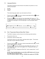
1
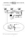
THERMOMAX
NETLINK
HARDWARE
USER MANUAL
BENUTZERHANDBUCH
ENGLISH & DEUTSCH
A8027A
CONTENTS
INTRODUCTION …………………………………………….......……..………… 2
GENERAL DESCRIPTION ………………………………………...……...…….. 3
SECTION 1
CONNECTING THE NETLINK HARDWARE TO A PRINTER
1.1
SERIAL PRINTER …………………………………………...………….... 4
1.2
PARALLEL PRINTER ………………………………………...………….. 4
SECTION 2
NETWORKING A THERMOMAX UNIT USING THE NETLINK HARDWARE
2.1
CONNECTING DIAGRAM ……………………………………...……….. 5
2.2
FINDING THE ELECTRONIC SERIAL NUMBER OF ANY
THERMOMAX DATALOGGING UNIT ……………………………....….. 6
2.3
SETTING UP A THERMOMAX NETWORK USING THE
MASTERLINK SOFTWARE …………………………………...…….
8
SECTION 3
SETTING UP & PRINTING WITH THE NETLINK HARDWARE
3.1
NETLINK PRINT CONTROL FUNCTIONS ………………………......… 11
3.2
CHANGING THE PRINTER BETWEEN PARALLEL AND
SERIAL MODE ………………………………………………...........……. 11
3.3
LANGUAGE SELECTION ………………………………………….......... 12
3.4
PRINT “TEMPERATURE DATA + ALARM DATA” OPTION” …........... 12
3.5
CURRENT NETLINK STATUS ………………………........…………….. 13
3.6
PRINT FUNCTIONS …………………………………………........……… 13
SECTION 4
SPECIFICATION …………………………………………………………….....…. 14
DEUTSCHE GEBRAUCHSANWEISUNG ……………………….....………….. 16
1
INTRODUCTION
The Netlink Hardware is a small compact unit that may be connected to any
Thermomax Datalogger product to offer the following options:
NETWORKING
To connect an individual Thermomax Datalogger product as part of a Thermomax
Network of up to 32 units.
The Masterlink Software package then facilitates the download of data from any unit
on the network.
The Netlink Hardware may be used to connect any of the following:
SM UNO
SM UNO M
SM DUE
SM QUATTRO
SMX 100
MDX 100
NOTE: The LCT-2 Network Datalogger may be connected directly to a Thermomax
network without the need for a Netlink Hardware.
PRINTING
Any Thermomax Datalogger unit can be connected via the Netlink Hardware to a
standard PC Printer or a Thermomax Serial Printer, (Part No. A6747). This
eliminates the need for a PC.
2
GENERAL DESCRIPTION
1.
2.
3-4
5
Serial Link for connecting a Thermomax unit to the Netlink Hardware, (using
8W shielded cable assembly : 1m (black), Pt. No. A6243).
For connecting the Netlink Hardware to a parallel printer, (using A6724 grey
Cable assembly).
Network Connections
These connectors are used to link up the Netlink Hardware within a
Thermomax Network, (see section 2).
Connection for:
(i)
Serial Link for connecting the Netlink Hardware to a P.C.
(ii)
Serial Link for connecting the Netlink Hardware to a Thermomax Serial
Printer, (using cable A7433).
11
8
10
1
9
6
12
7
2
4
5
3
PRINTER MODE:
6
This green LED illuminates to indicate that the
key has been pressed.
7
This green LED illuminates to indicate that the
key has been pressed.
8
This green LED illuminates to indicate that the
key has been pressed.
9
Pressing the
key allows the user to print 1 day’s temperature data.
10
Pressing the
key allows the user to print 3 day’s data.
11
12
key allows the user to print the data from all days.
Pressing the
For all units supplied outside the UK, an external 12V DC power supply
(1.3mm DC connector) must be used. This is available from Thermomax, (Pt
no. A6249).
3
SECTION 1
CONNECTING THE NETLINK HARDWARE TO A PRINTER
1.1
Serial Printer
1.2
Parallel Printer
4
SECTION 2
NETWORKING A THERMOMAX UNIT USING THE NETLINK
HARDWARE
2.1
Connecting Diagram
The PC may be connected to any Netlink Hardware unit.
5
2.2
Finding the Electronic Serial Number of any Thermomax Datalogging
Unit
In order to connect ant Thermomax Datalogging unit to the Thermomax
Network, you must know the Electronic Serial Number of that unit. This is
how the network addresses each individual unit. (See section 2.3 – Setting
up a Thermomax Network using the Masterlink 3.1 Software).
For each standard unit, the diagnostic screen can be found in the following
way.
Note: The user should start from the main screen and follow the steps below.
SM UNO / UNO M
1.
Press the
key twice.
2.
Use the
keys to move to the
3.
4.
Press the
key to reveal the diagnostic screen.
The electronic serial number will be displayed at the top of this screen.
window.
SM-UNO DIAGNOSTICS
XX XX XX
SM QUATTRO
1.
Press the
key twice.
2.
Use the
keys to move to the
3.
4.
Press the
key to reveal the diagnostic screen.
The electronic serial number will be displayed at the top of this screen.
window.
SM QUATTRO DIAGNOSTICS
XX XX XX
SMX 100
1.
2.
Press the
key three times to reveal the diagnostic screen.
The electronic serial number will be displayed at the top of this screen.
SMX 1.4 (CAL 31 JAN 98)
6
XX XX XX
SM DUE / DUE DL
1.
Press the
key twice.
2.
Use the
keys to move to the
3.
4.
Press the
key to reveal the diagnostic screen.
The electronic serial number will be displayed at the top of this screen.
window.
SM-DUE DL DIAGNOSTICS
XX XX XX
MDX 100
1.
2.
Press the
key twice to reveal the diagnostic screen.
The electronic serial number will be displayed at the top of this screen.
MDX 1.4 (CAL 31 JAN 98)
XX XX XX
LCT 2
The LCT-2 STANDARD version, (C0450), requires the Netlink hardware
module, but the LCT-2 NETWORK version, (C0422), does not as all
networking capabilities are built into this unit. The LCT 2 ’s electronic serial
number can be found as follows:
1.
Press and hold the
key until the following message is displayed:
“DEUTSCH
FRANC
OR S TO CONTINUE”
key again.
2.
Press the
3.
Press and hold the
key until the following message is displayed:
“LCT 2 XX XX XX”
“ VERSION 1.1 “
The Network option is available on the LCT-2, C0422, from serial number
C0422DE10491, manufactured from March 1998.
The digit denoted by XX XX XX in all above represents the electronic serial
number of each unit.
7
2.3
Setting Up a Thermomax Network Using the Masterlink Software
To enable the Network Option of the software, click on the “Options” menu,
select “Preferences” from this menu and the following window will appear.
1
2
above. A ✔ indicates that
1
To enable the Network, click the selection box
the Network option has been selected.
2
The PC COM port is selected by clicking the
key. You may then select
COM 1 to COM 4. This should correspond to the COM port, which is
connected to the Masterlink cable.
When the Network option is selected, the user may now access the
“Configure Network” option from the “Comms” menu.
Here the user has the option to add new units to the network and then ‘setup’ all the parameters for each unit. This option can also be used to modify
existing units on the network.
8
There are 32 Network slots. You can “set-up” “edit” or delete any one of
these 32 possible units by selecting the number as highlighted by
below.
1
The Delete key will remove a unit from the Network. By clicking the “edit” key,
the following window will appear:
1
4
2
3
1
Here the user has the opportunity to enter a name for the unit.
2
Here the user must enter the electronic Serial number for the network unit.
The electronic serial number can be obtained in section 2.2 – Finding the
Electronic Serial Number of any Thermomax Datalogging Unit. This will also
be printed on the Calibration certificate of each LCT-2 unit.
9
3.
The “Test” key will communicate with the unit to ensure that all cables are
connected correctly and the entered electronic serial is valid. If this is the
case the following message is displayed:
If a cable is incorrectly connected or an invalid electronic serial number has
been entered the following message is displayed.
4.
The “Set-up” key can only be used in conjuction with the LCT-2 unit. This key
allows the user to program all the LCT-2 parameters such as alarm values,
time and date from a P.C. Should this operation be attempted on any other
Thermomax device the following error message is displayed.
10
SECTION 3
SETTING UP & PRINTING WITH THE NETLINK HARDWARE
3.1
Netlink Print Control Functions.
Each key on the Netlink hardware module has two separate functions. This
section describes the control features of the unit.
3.2
Changing the Printer between Parallel and Serial Mode
The Netlink Hardware module supports standard parallel and serial printer
options. The factory default mode is set to the parallel printer option. The
selected printer option may be checked as follows:
1
Power the unit up
2
The unit indicates the parallel printer option by flashing the green lamp
associated with key
3
The unit indicates the serial printer option by flashing the green lamp
associated with key
4
, four times.
, twice.
The Netlink Hardware will automatically print it’s “SETUP” information to both
parallel and serial printer outputs. This will detail the Software Version,
Language Selection, Parallel or Serial Mode of Operation and Data type
(temperature only or temperature + alarm). The user must now select a
serial or parallel printer as detailed below:
The serial printer option is selected as follows:
1
. The green indicator associated with key
Press and hold key
light for approximately 7 seconds.
2
when the indicator lamp associated with it goes out. The
Release key
printer option has now changed to serial mode.
3
To return to the parallel print mode option repeat points 1 and 2 above.
Parallel
Serial
11
should
3.3
Language Selection
The Netlink hardware module allows for the data to be printed out in the
following languages.
1
2
3
English
German
French
The desired language option may be selected as follows:
1
. The green indicator associated with key
Press and hold key
light for approximately 7 seconds.
2.
when the indicator lamp associated with it goes out. The
Release key
language option has now changed as per the list. Step 1. Should be repeated
to change the language to the next language on the list (English follows
French).
English
3.4
German
should
French
Print “Temperature Data and Alarm Data” Option
The Netlink hardware module allows for the following printed options:
1
2
Temperature data only.
Temperature data and Alarm data.
Temperature data only is the factory selected default option. The desired
data option may be selected as follows:
1
. The green indicator associated with key
Press and hold key
light for approximately 7 seconds.
2
when the indicator lamp associated with it goes out. The
Release key
“Print Data type” option has now changed to the “Temperature data and
Alarm data” option.
To return to the “Print Temperature Data Only” option repeat points 1 and 2
above.
3
should
NOTE: If the Humidity Option is used with an SM Quattro unit, the user
must add 50 to the printed value.
E.g. If the printout shows a value of 1.5%RH, this equates to 51.5%RH.
12
3.5
Current Netlink Status
The Netlink hardware module also allows for its current status to be printed.
The following information is contained in the status report:
1.
Software Version
2.
Printer Type (Parallel or Serial)
3.
Language (English, German or French)
4.
Data Type (Temperature Only or Temperature + Alarm)
A status report is obtained as follows:
1
Press and hold keys
and
and
. The green indicator associated with keys
should light for approximately 7 seconds.
2
Release keys
and
when the indicators associated with both lamps go
out. The Netlink hardware module will now print a status report.
3.6
Print Functions
After Selecting the desired printer options i.e.-Printer type, Language and
Data type as described above, the Netlink hardware module can be used to
print data directly from any Thermomax data logging unit. The following
options are available:
1
Print one day’s data (Key
2
Print three day’s data (Key
3
Print all day’s data (Key
).
).
).
To achieve any of the above print cycles the desired key should be
momentarily pressed. The appropriate indicator lamp should blink and a print
cycle is instigated on the attached printer.
13
SECTION 4 SPECIFICATION
DIMENSIONS
Width:146mm
Height:
29mm
Depth:
94mm
Weight:
0.17kg
Box material:
Front Panel:
Display:
Plastic
Reverse Printed
LED Display
Ambient Temperature:
0°C - 40°C
PARTS LIST
NETLINK HARDWARE (UK)
NETLINK HARDWARE (STANDARD)
C0315
C0316
ACCESSORIES
SERIAL PRINTER LEAD (BLACK)
SERIAL PRINTER
PARALLEL PRINTER LEAD (GREY)
NETLINK SWITCH BOX
SWITCH BOX CABLE ASSEMBLY (IVORY)
NETLINK CONNECTING CABLE : 1m (IVORY)
NETLINK CONNECTING CABLE : 10m (IVORY)
NETLINK CONNECTING CABLE : 20m (IVORY)
NETLINK CONNECTING CABLE : 50m (IVORY)
NETLINK CONNECTING CABLE : 100m (IVORY)
NETLINK CONNECTING CABLE : 200m (IVORY)
8W SHIELDED CABLE ASSEMBLY : 1m (BLACK)
8W SHIELDED CABLE ASSEMBLY : 10m (BLACK)
8W SHIELDED CABLE ASSEMBLY : 20m (BLACK)
8W SHIELDED CABLE ASSEMBLY : 40m (BLACK)
MASTERLINK SOFTWARE VERSION 3.1
MASTERLINK EXTENSION KIT : 20m (IVORY)
MASTERLINK EXTENSION KIT : 40m (IVORY)
12V REGULATED DC POWER SUPPLY
MAINS CHARGER
14
A7433
A6747
A6724
A6113
A7000
A7004
A7426
A7427
A7428
A7429
A7431
A6243
A6743
A6244
A6246
C0322
A7378
A7342
A6249
A6821
CE
This product has been tested to the EU EMC 89/336/EEC directive according to the
manufacturer’s report, which is available on request.
Thermomax certifies that this datalogger has been manufactured to an ISO 9002
Quality System.
Thermomax undertakes to repair or replace the device if same is shown to be
defective in its manufacture and/or components but Thermomax shall not be
responsible for any other financial or economic loss (or any indirect loss) which may
be incurred by the buyer/customer or others in the use of the device.
Any claim for repair or replacement must be made not later than 15 months after the
date of manufacture.
15