1
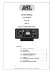
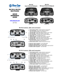
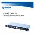
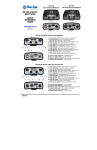
KB/HB-Series
INSTALLATION INSTRUCTIONS
EB7-4W Module
Clear-Com’s EB7-4W 4-Wire Option module can be added to the KB-702, KB702GM, KB-701, and HB-702 products. This option allows the speaker or
headset station to be operated over longer distances than are possible with a
standard Clear-Com intercom line. This option can also be used to connect
with fiber optic transmission equipment. The EB7-4W 4-Wire Option module
connection is a transformer-isolated, audio-only connection and does not
convey the call signal. The module also requires local powering.
Two-channel stations can have two separate 4-wire connections with this
option. The Channel Switch on the front panel selects which channel is
connected.
Installation
The EB7-4W plugs onto one- or two-channel speaker or headset stations as
illustrated in Figure 1.
Channel A
Connection
Retaining
Screws
Channel B
Connection
P2 Must be
installed if
no option
EB7-4W
Option
Power
Connection
4-Wire
Option
View from top
of KB-702
1 2 3
Front Panel
Figure 1: Installation Diagram
PN 810382Z Rev. 1
1
© Clear-Com Communication Systems
KB/HB-Series EB7-4W Module
Clear-Com Communication Systems
Use the following steps to install the EB7-4W Option Module:
1. Remove the two screws from the station’s main circuit board and
replace them with the supplied jackscrews.
2. Remove plugs P1 and P3. Retain these plugs for possible future use.
3. Plug the EB7-4W Option onto the main circuit board where P1 and
P3 were plugged.
4. Fasten the EB7-4W in place with the two screws removed in step 1.
Powering the Station
When the EB7-4W is installed, the speaker or headset station requires local
power, which can be obtained from the following sources:
20-30VDC
A suitable DC source is the Clear-Com 400067Z 30V 500mA AC-DC
converter.
14-20VAC
A suitable AC source is a doorbell transformer. This can be fitted in a
separate box that will contain the power-line connection and the low-voltage
output can be routed to the connector on the EB7-4W circuit board.
Note: Different types of doorbell transformers are commonly available at
hardware stores. Ensure that the output voltage is suitable for use with
the EB7-4W.
Warning: Always follow local electrical codes. Do not install mains wiring in
the same electrical box as the speaker or headset station.
Connect the two wires from the power source to the two-position, plug-on
terminal strip supplied with the 4-Wire Option. Plug this connector onto the
EB7-4W circuit board as shown in Figure 1.
PN 810382Z Rev. 1
2
© Clear-Com Communication Systems
Clear-Com Communication Systems
KB/HB-Series EB7-4W Module
Wiring the 4-Wire Module
The intercom line connector on the main circuit board does not function when
the EB7-4W is installed. Instead, the 4-wire intercom connections are made to
the connectors on the EB7-4W circuit board. For each channel, “Audio Out”
and “Audio In,” pairs are provided. Both are balanced, 600-ohm connections.
An optional jumper can be installed if the receive signal is noisy. This adds a
resistive termination to the receive Audio In signal, reducing the level by 6 to 8
dB. Typical wiring is as shown in Figure 2.
Channel A
Audio Out
Optional Receive Jumper
Channel A
Audio In
Channel B
Audio Out
Optional Receive Jumper
Channel B
Audio In
Pin 1
Pin 1
Power In
Figure 2: Typical EB7-4W Wiring
•
4-Wire Intercom Line Connections: When the EB7-4W is used, the
intercom connections to each channel are made to five-terminal plugon connectors on the EB7-4W circuit board instead of to the connector
on the KB-701 circuit board. The connections for each pin are visible
on the circuit board when the connector is unplugged. The connector
pinout for each channel is as follows:
•
Pins 1 and 2—Intercom Audio Input (audio to the speaker or
headset)
•
Pin 3—Optional Receive Jumper (used if receive signal is noisy)
•
Pins 4 and 5—Intercom Audio Output (audio from the
microphone).
When the KB-702 is used, the 4-wire intercom connection must be
made to the Channel B connector.
© Clear-Com Communication Systems
3
PN 810382Z Rev. 1
KB/HB-Series EB7-4W Module
Clear-Com Communication Systems
Specifications
EB7-4W Input
>=5KΩ
>=10dB
Input Impedance
Max Level before Clipping
EB7-4W Output
<=600Ω
Output Impedance
Power
AC Input Voltage Range
DC Input Voltage Range
Input Current (Max)
PN 810382Z Rev. 1
14-20 VAC
20-30 VDC
<= 15mA
(excluding KB/HB
station current)
4
© Clear-Com Communication Systems
LIMITED WARRANTY
Vitec Group Communications (VGC) warrants that at the time of purchase, the
equipment supplied complies with any specification in the order confirmation
when used under normal conditions, and is free from defects in workmanship
and materials during the warranty period.
During the warranty period VGC, or any service company authorized by VGC,
will in a commercially reasonable time remedy defects in materials, design, and
workmanship free of charge by repairing, or should VGC in its discretion deem it
necessary, replacing the product in accordance with this limited warranty. In no
event will VGC be responsible for incidental, consequential, or special loss or
damage, however caused.
WARRANTY PERIOD
Return Material
Authorization (RMA)
numbers are required for all
returns.
Both warranty and
non-warranty repairs are
available.
The product may consist of several parts, each covered by a different warranty
period. The warranty periods are:
• Cables, accessories, components, and consumable items have a limited
warranty of 90 days.
• Headsets, handsets, microphones, and spare parts have a limited warranty of
one year.
• UHF wireless IFB products have a limited warranty of one year.
• UHF wireless intercom systems have a limited warranty of three years.
• All other Clear-Com and Drake brand systems and products, including
beltpacks, have a limited warranty of two years.
The warranty starts at the time of the product’s original purchase. The warranty
start date for contracts which include installation and commissioning will
commence from the earlier of date of the Site Acceptance Test or three months
from purchase.
TECHNICAL SUPPORT
To ensure complete and timely support to its customers, VGC’s User Support
Center is staffed by qualified technical personnel. Telephone and email technical
support is offered worldwide by the User Support Center.
The User Support Center is available to VGC’s customers during the full course
of their warranty period.
Instructions for reaching VGC’s User Support Centers are given below.
Telephone for Europe, Middle East and Africa: +49 40 6688 4040 or +44 1223
815000
WARRANTY
i
Telephone for the Americas and Asia: +1 510 337 6600
Email: [email protected]
Once the standard warranty period has expired, the User Support Center will
continue to provide telephone support if you have purchased an Extended
Warranty.
For latest contact information please refer to the Service and Support section at
www.clearcom.com.
WARRANTY REPAIRS AND RETURNS
Before returning equipment for repair, contact a User Support Center to obtain a
Return Material Authorization (RMA). VGC representatives will give you
instructions and addresses for returning your equipment. You must ship the
equipment at your expense, and the support center will return the equipment at
VGC’s expense.
For out-of-box failures, use the following contact information:
Europe, Middle East and Africa
Tel: +44 1223 815000 Email: [email protected]
North America, Canada, Mexico, Caribbean & US Military
Tel: +1 510 337 6600 Email: [email protected]
Asia Pacific & South America
Tel: +1 510 337 6600 Email: [email protected]
VGC has the right to inspect the equipment and/or installation or relevant
packaging.
For latest contact information please refer to the Service and Support section at
www.clearcom.com.
NON-WARRANTY REPAIRS AND RETURNS
For items not under warranty, you must obtain an RMA by contacting the User
Support Center. VGC representatives will give you instructions and addresses for
returning your equipment.
You must pay all charges to have the equipment shipped to the support center
and returned to you, in addition to the costs of the repair.
EXTENDED WARRANTY
You can purchase an extended warranty at the time of purchase or at any time
during the first two years of ownership of the product. The purchase of an
extended warranty extends to five years the warranty of any product offered with
a standard two-year warranty. The total warranty period will not extend beyond
five years.
ii
WARRANTY
Note: VGC does not offer warranty extensions on UHF wireless intercom
systems, or on any product with a 1-year or 90-day warranty.
LIABILITY
THE FOREGOING WARRANTY IS VGC'S SOLE AND EXCLUSIVE
WARRANTY. THE IMPLIED WARRANTY OF MERCHANTABILITY
AND FITNESS FOR A PARTICULAR PURPOSE AND ANY OTHER
REQUIRED IMPLIED WARRANTY SHALL EXPIRE AT THE END OF
THE WARRANTY PERIOD. THERE ARE NO OTHER WARRANTIES
(INCLUDING WITHOUT LIMITATION WARRANTIES FOR
CONSUMABLES AND OTHER SUPPLIES) OF ANY NATURE
WHATSOEVER, WHETHER ARISING IN CONTRACT, TORT,
NEGLIGENCE OF ANY DEGREE, STRICT LIABILITY OR OTHERWISE,
WITH RESPECT TO THE PRODUCTS OR ANY PART THEREOF
DELIVERED HEREUNDER, OR FOR ANY DAMAGES AND/OR LOSSES
(INCLUDING LOSS OF USE, REVENUE, AND/OR PROFITS). SOME
STATES DO NOT ALLOW THE EXCLUSION OR LIMITATION OF
INCIDENTAL OR CONSEQUENTIAL DAMAGES OR THE
LIMITATION ON HOW LONG AN IMPLIED WARRANTY LASTS, SO
THE ABOVE LIMITATIONS MAY NOT APPLY TO YOU. IN ANY
EVENT, TO THE MAXIMUM EXTENT PERMITTED UNDER
APPLICABLE LAW, VGC'S LIABILITY TO CUSTOMER HEREUNDER
SHALL NOT UNDER ANY CIRCUMSTANCES EXCEED THE COST OF
REPAIRING OR REPLACING ANY PART(S) FOUND TO BE
DEFECTIVE WITHIN THE WARRANTY PERIOD AS AFORESAID.
This warranty does not cover any damage to a product resulting from cause other
than part defect and malfunction. The VGC warranty does not cover any defect,
malfunction, or failure caused beyond the control of VGC, including
unreasonable or negligent operation, abuse, accident, failure to follow
instructions in the manual, defective or improperly associated equipment,
attempts at modification and repair not approved by VGC, and shipping
damage. Products with their serial numbers removed or defaced are not covered
by this warranty.
This warranty does not include defects arising from installation (when not
performed by VGC), lightning, power outages and fluctuations, air conditioning
failure, improper integration with non-approved components, defects or failures
of customer furnished components resulting in damage to VGC provided
product.
This limited warranty is not transferable and cannot be enforced by anyone other
than the original consumer purchaser.
This warranty gives you specific legal rights and you may have other rights which
vary from country to country.
WARRANTY
iii
iv
WARRANTY


![User Manual PS 430 [ASL]](http://vs1.manualzilla.com/store/data/005676322_1-235f4942ab78942bc49f054c2ec420ac-150x150.png)