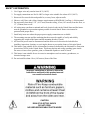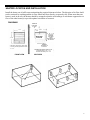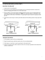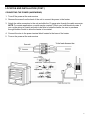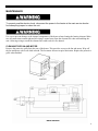
1
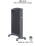
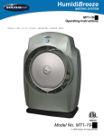
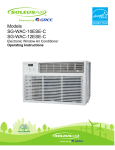
HI1-50-03 Industrial Utility Heater
3092402
HI1-50-03
© 2011 Soleus Air International
Thank you for choosing a Soleus Air Utility Heater. This owner’s manual will provide you
with valuable information necessary for the proper care and maintenance of your new product.
Please take a few moments to thoroughly read the instructions and familiarize yourself with all
the operational aspects of your new heater.
For your own records, please attach a copy of your sales receipt to this manual. Also, write the
store name/location, date purchased, and serial number below:
Store Name: ____________________________________________________
Location: ______________________________________________________
Date Purchased: _________________________________________________
Serial Number (located on back of unit): ______________________________
IMPORTANT INSTRUCTIONS
When using this electric unit, basic safety precautions should always be followed to reduce the risk of fire,
electric shock, and injury to persons, including the following:
1. Read ALL instructions before using this unit.
2. CAUTION: Risk of Electric Shock. DO NOT open or try to repair the heater yourself.
3. This heater may get hot when in use. To avoid burns, DO NOT let bare skin touch hot surfaces. If
provided, use handles when moving this heater.
4. Keep combustible materials, such as furniture, pillows, bedding, paper, clothes, and curtains at
least 3 ft from the front of the heater and keep them away from the sides, top, and rear. DO NOT
place towels or other objects on the heater.
5. Extreme caution is necessary when any heater is used by or near children or the disabled, or when
the heater is left operating and unattended.
6. DO NOT operate any heater with a damaged cord or after the heater malfunctions, has been
dropped or damaged in any manner. Return heater to authorized service facility for examination,
electrical or mechanical adjustment, or repair.
7. This heater is not intended for use in bathrooms, laundry areas and similar indoor locations.
NEVER locate heater where it may fall into a bathtub or other water container. To protect against
electrical hazards, DO NOT immerse in water or other liquids.
8. DO NOT do any field-wiring connection with wet hands.
9. DO NOT run cord under carpeting. DO NOT cover cord with throw rugs, runners, or similar coverings. Arrange cord away from traffic area and where it will not be tripped over.
10. DO NOT insert or allow foreign objects to enter any ventilation or exhaust opening as this may
cause an electric shock or fire, or damage the heater.
11. To prevent a possible fire, DO NOT block the air intakes or exhaust in any manner. DO NOT use
2
on soft surfaces, like a bed, where openings may become blocked.
12. A heater has hot and arcing or sparking parts inside. DO NOT use in areas where gasoline, paint,
explosive and/or flammable liquids are used or stored. Keep unit away from heated surfaces and
open flames.
13. Avoid the use of an extension cord because the extension cord may overheat and cause a risk of
fire.
14. To avoid fire or shock hazard, connect the unit directly to a 240V AC power source.
15. Use only for intended use as described in this manual. Any other use not recommended by the
manufacturer may cause fire, electric shock, or injury to persons. The use of attachments not recommended or sold by unauthorized dealers may cause hazards.
16. WARNING: To reduce the risk of fire or electric shock, DO NOT use this unit with any solid-state
speed control device.
17. DO NOT attempt to repair or adjust any electrical or mechanical functions on this unit. Doing so
will void your warranty. The inside of the unit contains no user serviceable parts. Qualified personnel should perform all servicing only.
18. Connect to properly grounded power source only.
19. SAVE THESE INSTRUCTIONS.
3
SAFETY INFORMATION
1.
2.
3.
4.
5.
Use Copper wire only rated at least 60°C (140°F)
For supply connections use No.10 AWG or larger wires suitable for at least 60°C (140°F)
Heater air flow must be directed parallel to, or away from, adjacent walls.
Observe wall, floor, and ceiling clearance requirements on DIAGRAM 1 on Page 6 of this manual.
Do not install closer than 1 5/8” (41.27mm) from the ceiling, 6 feet (1.83 meters) from the floor, or
13” (330mm) from a wall
6. All wiring must comform to national and local electrical codes in the United States and the heater
must be grounded as a precaution against possible electrical shock. Heater circuit must be
protected with proper fuses.
7. Install only in an area where the proper power-supply connections are available.
8. The mounting structure and the anchoring hardware must be capable of easily and reliably
supporting the weight of the heater and the mounting bracket (if used).
9. All electrical power must be disconnected and the main service box must be locked before
installing, inspection, cleaning, or servicing the heater to prevent the chance of electrical shock.
10. This heater is not suitable for use in hazardous locations as definied by the National Fire Protection
Association (NFPA) in the United States. This heater has hot and arcing (sparking) parts inside.
Do not use in ares where gasoline, paint, or flammable liquids are used or stored.
11. This heater is not suitable for use in corrosive atmospheres such as marine, greenhouses, or
chemical storage areas.
12. Do not install less than 6 feet (1.83 meters) from of the floor.
Improper installation or failure to follow the
instructions outlined in this product manual
can result in electrical shock.
CAUTION
RISK OF ELECTRIC SHOCK
DO NOT OPEN
NO USER-SERVICEABLE PARTS INSIDE
4
SPECIFICATIONS
Voltage Rating / Amps
208V-240 V / 21 Amps / Single Phase
Power Consumption
5000 Watts
Heating BTU’s
17,100 BTU
Air Flow
270 CFM
Unit Size
15.7 inches. (W) x 11.29 inches. (D) x 14.37 inches. (H)
Unit Weight
27.00 lbs.
5
HEATER LOCATION AND INSTALLATION
Install the heater out of traffic areas maintaining the required clearances below. The direction of air flow shold
not be restricted by anything and the air flow should not blow directly at exposed walls. When more than one
heater is used in an area, the heaters should be arranged so that the air discharge of each heater supports the air
flow of the other heater(s) to provide optimal circulation of warm air
DIAGRAM 1
MINIMUM
DISTANCE
TO WALL
13”
11.29”
15.7”
5 1/2”
24”
MOUNTING
LOCATION
14.37”
Note: Min. clearance to ceiling when
not using mounting brackets is 1 5/8”
MINIMUM
DISTANCE
FROM
DISCHARGE TO
ANY OBJECT
MINIMUM
DISTANCE TO
FLOOR 6 ft.
MAXIMUM MOUNTING HEIGHT FOR:
Vertical air delivery unit = 11 ft.
Horizontal air delivery unit = 8 ft.
FRONT VIEW
SIDE VIEW
6
LOCATION AND INSTALLATION (CONT.)
MOUNTING THE BRACKET
1. Locate a stud in the ceiling joist.
2. Remove the mounting bracket from the heating unit be loosening the bracket screws with a
wrench and slipping the handle off over the screw heads.
3. Place a washer on the screws before inserting through the holes in the mounting bracket and
screw them securely into the ceiling joist. NOTE: If you want the heater to swivel side to side,
add a washer to both sides of the bracket. A longer lag bolt may be required to properly secure
the unit.
4. Tighten the screw enough to securely hold the heater with the airflow pointed in the proper direction.
SINGLE –SCREW MOUNTING
DOUBLE –SCREW MOUNTING
HANGING THE HEATER
1. Lift the heater up and into the mounting bracket.
2. Align the bracket screws with the keyhole slots in the mounting brackets
3. If the heater is to be tilted, it must be positioned in the keyhole slots.
4. Tighten the bracket screws with a wrench so the unit is securely suspended at the desired horizontal or vertical level.
7
LOCATION AND INSTALLATION (CONT.)
CONNECTING THE POWER (HARDWIRING)
1. Turn off the power at the main service
2. Remove the screw from the back of the unit to connect the power to the heater.
3. Attach the cable connectors to the unit and slide the 10 gauge wire through the cable connector.
NOTE: For certain applications, conduit may be required. Check your local electrical codes. If
you run the wiring in conduit and wish to be able to rotate the heater, be sure to purchase
enough flexible conduit to allow the heater to be rotated.
4. Connect the wire to the power terminal block located in the base of the heater.
5. Turn on the power at the main service.
208V-240V
8
LOCATION AND INSTALLATION (CONT.)
CONNECTING THE HEATER TO A 208V-240V / 30AMP PLUG (SOLD SEPARATELY)
1. Remove the screws from the back of the unit to remove the cover .
2. Attach the 208V-240V / 30 AMP Plug to the heater using the Live (Also called “Line” or “Hot”),
Neutral, and Ground wires from the plug .
3. Connect the wires to the corresponding connections on the power terminal block located in the
base of the heater.
4. Connect the plug to a 208V-240V / 30Amp outlet.
9
OPERATION
NOTE: The first time you operate this heater, it may emit a slight odor and some smoke. This is due
to the residual cleaning agents used to clean the element during manufacturing. This is normal operation and will cease after the heater has been used for a few minutes.
ADJUSTING THE AIR FLOW DIRECTION
1. Rotating the unit - if the unit has been installed with a single lag bolt, simply rotate the entire unit
as needed to adjust the direction of the air flow.
2. Tilting the unit - Loosen the bracket screws, tilt the heater to the desired position, and re-tighten
the bracket screws. NOTE: To tilt the heater it must be mounted in bottom keyhole slots of
mounting brackets to maintain adequate clearance and prevent possible overheating.
3. Adjust the louvers to the desired position. NOTE: The louvers are designed so they cannot be
completely closed. Do not attempt to close the louvers completely as this may damage the unit.
.
To prevent possible electric shock, disconnect the power to the heater at the main service box before attempting to adjust the heat output of the unit.
10
MAINTENANCE
To prevent possible electric shock, disconnect the power to the heater at the main service box before attempting inspect or clean the unit.
Use care to prevent damage to the internal components of the heater when cleaning the heating element. Make
sure all connections remain tight and all wiring is routed away from the element fins when reassembling the
unit. Allowing wiring to touch the element fins could result in a fire hazard.
CLEANING THE FAN AND MOTOR
Remove the protective grille from the rear of the heater. This provides access to the fan and motor. Wipe off
the fan and motor with a soft cloth or brush. The fan motor does not require lubrication. Replace the protective
grille when finished.
WIRING DIAGRAM
11
WARRANTY
One Year Limited Warranty
Soleus International Inc. warrants the accompanying Soleus Air Heater to be free of defects in material and workmanship for the applications specified in its operation instruction for a period of ONE (1) year from the date of original retail purchase in the United States.
If the unit exhibits a defect in normal use, Soleus International Inc. will, at its option, either repair or replace it, free of
charge within a reasonable time after the unit is returned during the warranty period.
As a condition to any warranty service obligation, the consumer must present this Warranty Certificate along with a
copy of the original purchase invoice.
THIS WARRANTY DOES NOT COVER:
• Damage, accidental or otherwise, to the unit while in the possession of a consumer not caused by a defect in
material or workmanship.
• Damage caused by consumer misuse, tampering, or failure to follow the care and special handling provisions
in the instructions. This includes dents, accidental or otherwise, to the base and head of the unit.
• Damage to the finish of the case, or other appearance parts caused by wear.
• Damage caused by repairs or alterations of the unit by anyone other than those authorized by Soleus
International Inc.
• Freight and Insurance cost for the warranty service.
ALL WARRANTIES, INCLUDING ANY IMPLIED WARRANTY OF MERCHANT ABILITY ARE LIMITED TO
ONE-YEAR DURATION OF THIS EXPRESS LIMITED WARRANTY. SOLEUS INTERNATIONAL INC.
DISCLAIMS ANY LIABILITY FOR CONSEQUENTIAL OR INCIDENTAL DAMAGES AND IN NO EVENT
SHALL SOLEUS INTERNATIONAL INC’S LIABILITY EXCEED THE RETAIL VALUE OF THE UNIT FOR
BREACH OF ANY WRITTEN OR IMPLIED WARRANTY WITH RESPECT TO THIS UNIT.
This warranty covers only new products purchased from our authorized dealers or retailers. It does not cover used, salvaged, or refurbished products.
As some states do not allow the limitation or exclusion of incidental or consequential damages, or do not allow
limitation on implied warranties, the above limitations and exclusions may not apply to you. This warranty gives you
specific legal rights, and you may also have other rights that vary from state to state.
For Technical Support or Warranty Service
Please Call (888) 876-5387
Or Write To:
Soleus International Inc.
20035 E. Walnut Dr. N.
City of Industry, CA 91789 USA
www.soleusair.com
12