1
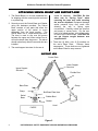
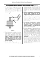
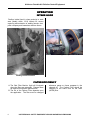
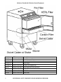
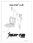
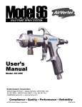
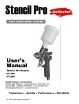
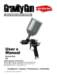
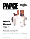
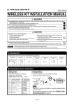
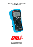
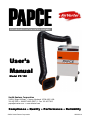
PAPCE
PORTABLE AIR POLLUTION CONTROL EQUIPMENT
U s e r’ s
Manual
Model PP-150
Smith Eastern Corporation
10630-S Riggs Hill Road • Jessup, Maryland 20794-9425 USA
301.497.7600 • 800.937.HVLP (4857) • Fax 301.497.7613
[email protected] • www.airverter.com
Compliance • Quality • Performance • Reliability
©2001 Smith Eastern Corporation
2002-03-14
AirVerter® Portable Air Pollution Control Equipment
Please Read User's Manual BEFORE
Using This Equipment
WHEN IN THE PROXIMITY OF HAZARDOUS FUGITIVE EMISSIONS
USE PROPER PERSONAL SAFETY EQUIPMENT INCLUDING
RESPIRATOR, GOGGLES AND SAFETY CLOTHING.
WARNING
THIS EQUIPMENT IS OPERATED WITH HIGH VOLTAGE ELECTRICITY.
ALWAYS TURN THE MACHINE "OFF" AND DISCONNECT POWER
PRIOR TO MAINTENANCE OR REPAIR.
WARRANTY
Smith Eastern Corporation warrants to the Purchaser that Portable Air Pollution Control Equipment
(PAPCE) is free from defects in material or workmanship under normal use and service for a period of
twelve (12) months from the date of shipment.
Should any failure appear during this period, Smith Eastern shall, if given prompt written notice by the
Purchaser, correct such nonconformity by repair or replacement of the nonconforming part, F.O.B.
Smith Eastern’s repair facility. Repair parts are warranted for ninety (90) days from the date of
shipment, but repairs or replacements to original equipment shall not renew or extend the warranty
period of such equipment.
Equipment and parts furnished by Smith Eastern but manufactured by others shall be limited to the
warranty offered by the manufacturer thereof.
Smith Eastern reserves the right to limit this warranty in cases of misuse or abuse. Any modifications
to equipment or recommended procedures will void the warranty.
The foregoing warranty is exclusive and in lieu of other warranties of quality or performance,
expressed, implied or statutory, including any warranties of merchantability or of fitness for a particular
purpose.
ABOUT PAPCE
PAPCE is a California South Coast Air Quality Management District (SCAQMD) approved portable
suction-type control device to capture fugitive vapor, mist, gases, fumes, odors, and other liquid and
solid particulate matter from spraying, sanding, grinding, and welding operations.
Contaminated air is drawn in through the exhaust hood and passes through the exhaust arm to the filter
unit. Large particles are removed from the air stream by the pre-filter. The HEPA filter removes
particles as small as .3 microns with 99% efficiency. An optional activated charcoal filter absorbs
hazardous gases and fumes. Filtered air is then returned to the workplace. The articulating, selfsupporting duct arm provides maximum flexibility in a portable particulate capture device.
2
USE PERSONAL SAFETY EQUIPMENT AROUND HAZARDOUS EMISSIONS
AirVerter® Portable Air Pollution Control Equipment
WARNING
Do not use this unit to extract easily flammable or explosive gases!
Protect the Electrical Cable from heat, oil and sharp edges.
Make sure the unit stands firmly and casters are locked when in operation.
Do not operate unit without filters installed.
Protect unit from dampness.
Disconnect from electrical power before servicing unit.
UNCRATING, ARM INSTALLATION AND
POWER SUPPLY VERIFICATION
Uncrate unit being careful not to damage the
Casters, Duct Support Arm and Collection Hood.
A. Verify all parts have been shipped and are
not damaged
1. Duct, Support Arm and Collection Hood
2. Large
Particulate
Filter
(Filter
Compartment)
3. HEPA Filter (Filter Compartment)
B. Attach Support Arm and Duct to the Swivel
Mount (see instructions on Attaching Swivel
Mounts and Support Arms.
FILTER INSTALLATION
Filters should be installed as follows:
A. Install filters in the filter compartment bottom
to top as follows:
1. HEPA Filter
2. Large Particulate Filter (Pre-Filter) - The
pre-filter should be installed with the less
dense side of the filter to the top and the
more dense side of the filter to the
bottom.
B. If used, the Carbon Filter is installed below
the HEPA Filter.
Particulate
Filter
HEPA
Optional
Carbon Filter
Figure 1
USE PERSONAL SAFETY EQUIPMENT AROUND HAZARDOUS EMISSIONS
3
AirVerter® Portable Air Pollution Control Equipment
ATTACHING SWIVEL MOUNT AND SUPPORT ARM
folded for shipment. CAUTION: Do Not
allow arm to “Spring Open” when
removing the tape and cords securing
the arm for shipment. Equipment damage
and/or personal injury may result from
allowing the arm to spring open
uncontrolled. Carefully unfold the structure
and ensure it moves freely. Put the arm
back in its folded position, as it will be easier
to mount to the Swivel Base. CAUTION: Do
not get fingers caught between arm
support tubes.
1. The Swivel Base is in its own cardboard box
for shipping with the mounting bolts enclosed
in a plastic bag.
2. Securely mount the Swivel Base and Gasket
using the hardware provided. The Swivel
Base consists of two parts that allow the
upper section of the swivel to move
separately from the lower section.
The
Swivel Base has a rubber-band-style boot.
The boot is used to slip over the groove
between the upper and lower sections so air
will not be drawn from the groove. The swivel
should rotate freely after the arm and duct are
installed.
3. The metal support structure for the arm is
4. There are (2) bolts, nuts, & (6) washers on
the arm's Base Plate.
Remove these
components. These bolts are not tightened
on the Base Plate for easy removal.
SUPPORT ARM
Center Plate
Lower Support
Structure
Upper Support
Structure
Flexible Duct
Base Plate
Clamp
Clamp
Bolt Base Plate Here
Swivel
Base
Rubber Boot
Gasket
Hood
PAPCE
Figure 2
4
USE PERSONAL SAFETY EQUIPMENT AROUND HAZARDOUS EMISSIONS
AirVerter® Portable Air Pollution Control Equipment
ATTACHING SWIVEL MOUNT AND SUPPORT ARM (continued)
5. The Base Plate has multiple holes for many
mounting configurations. You will use holes 1
& 8 for mounting the arm to the PAPCE. Bolt
the Base Plate/arm to the Swivel Base using
the hardware and holes 1 & 8. Tighten the
hardware snugly.
1
8
Figure 3
6. Extend the arm out by pulling on the lower
support structure. If the arm does not stay in
place, slightly tighten the friction pivots
located on the Base Plate and the Center
Plate.
These pivots use brown friction
washers. There are (2) pivots located on the
Base Plate and the Center Plate. Simply
adjust the pivot points until the arm holds
itself. Final pivot adjustment is to be done at
the end of assembly.
7. Slide the Flexible Duct over the arm and
attach the duct to the Swivel Base by using
the clamp provided. DO NOT ALLOW THE
FLEXIBLE DUCT TO GO OVER THE
GROOVE OR THE RUBBER BOOT THAT
COVERS THE GROOVE ON THE SWIVEL
BASE.
8. Mount the Hood using the hardware supplied
with the Hood.
Please note how the
hardware is positioned so the Hood will move
easily and stay at that point. Your Hood has
a built-in damper. Sometimes the damper
blade can be loose and may tend to close
during use. Tighten the small screw on the
damper lever so the damper will stay in its
desired position, yet will move so the damper
can be controlled.
9. The Hood has (2) pivot joints so the Hood
can be moved up, down, left, and right,
independent of the arm. The hardware that
mounted the Hood to the Hood arm bar
should be adjusted so the Hood can move
side to side and hold its position
10. Final arm adjustment is based upon the arm
holding itself in any position and not drifting.
This will require the tightening or loosening of
each of the pivot points located on the Base
Plate, Center Plate, Hood arm bar, and Hood.
The goal is to have the arm move as easily
as possible and hold its position at the
release point.
The arm may need
readjustment from time to time, dependent
upon usage.
11. DO NOT OVER TIGHTEN THE FRICTION
PIVOT JOINTS AS DAMAGE CAN OCCUR
TO THE FRICTION WASHERS.
IT IS
ALWAYS BETTER TO TIGHTEN THE
JOINTS A LITTLE AT A TIME TO GAIN THE
DESIRED MOVEMENT.
USE PERSONAL SAFETY EQUIPMENT AROUND HAZARDOUS EMISSIONS
5
AirVerter® Portable Air Pollution Control Equipment
OPERATION
INTAKE HOOD
Position Intake Hood in close proximity to work
area (ideally within 12-18 inches) for source
capturing and extraction of welding smoke, dust,
paint overspray and hazardous airborne fumes.
Sanding Dust Capture
Welding Fumes Extraction
FILTER EFFICIENCY
A. The Red Filter Monitor Light will illuminate
when the filters are saturated. Change filters
as required for optimum performance.
B. The life of the Carbon Filter depends upon
the application. The filter must be changed
6
whenever gases or fumes reappear in the
cleaned air. The Carbon Filter should be
changed at the same time as the main
(HEPA) filter.
USE PERSONAL SAFETY EQUIPMENT AROUND HAZARDOUS EMISSIONS
AirVerter® Portable Air Pollution Control Equipment
ILLUSTRATED PARTS BREAKDOWN
SUPPORT ARM AND FLEXIBLE DUCT
USE PERSONAL SAFETY EQUIPMENT AROUND HAZARDOUS EMISSIONS
7
AirVerter® Portable Air Pollution Control Equipment
Part #
NSN
Description
PP-006
4460-01-463-3165
Swivel Base and Gasket
PP-007-106
-
6-in. x 10-ft. Flexible Duct
PP-007-CL
-
Hose Clamp
PP-008-10
4460-01-463-3241
Flexible Duct Support Arm
PP-017
4330-01-467-6901
Large Particulate Filter (pre-filter)
PP-018
4460-01-463-3194
Carbon Filter
PP-019
4460-01-463-3190
HEPA Filter
PP-022
4460-01-463-3168
Intake Hood
8
USE PERSONAL SAFETY EQUIPMENT AROUND HAZARDOUS EMISSIONS
AirVerter® Portable Air Pollution Control Equipment
LARGE PARTICULATE FILTER (PRE-FILTER)
The Large Particulate Filter media is 100%
polyester. The dual-stage, layered media has a
less dense layer on the air-entering side and a
denser layer on the air-leaving side. This density
pattern prevents face loading as larger particles
are trapped in the front layer and smaller
particles in the back layer.
Applications include:
1. Paint Overspray
2. Sanding Dust
3. Oil Mist
4. Adhesive Overspray
Construction and Performance Data
Media Size
24" x 24" x 1"
Media
100% Polyester
Resistance @ 400 FPM
.20″ W.G.
Paint Holding Capacity
2.7 lbs. Per Sq. Ft.
HEPA FILTER
HEPA filters used in these units are designed for
use where higher airflow velocities occur offering
the user a wide range of advantages, including:
same amount of space, as do standard HEPA
filters. This was accomplished through the use of
a specially designed separator which allows up to
65% more media to be installed in a 24" x 24" x
11-1/2" area.
• Higher air flow with no increase in resistance.
• Higher velocities deliver up to 500 FPM while
maintaining the highest efficiencies.
The result for the user is a filter that lasts longer
and will operate at a higher capacity than typical
HEPA filters.
The filter has only .72" W.G. resistance at 1100
CFM, compared to 1.0" W.G. of standard HEPA
filters. The filter has more media area in the
.
Performance Data
DIMENSIONS
HxWxD
24 x 24 x 11-1/2
99.97% @ .3 Micron
CAPACITY (CFM) @ Initial Pressure Drop
1.0"
1.35"
1500
2000
USE PERSONAL SAFETY EQUIPMENT AROUND HAZARDOUS EMISSIONS
9
AirVerter® Portable Air Pollution Control Equipment
ACTIVATED CARBON FILTER
Carbon Filters are designed for odor removal
only. They are not for particulate collection.
Odor removal is a direct function of the amount of
carbon exposed to the air stream.
Carbon filters are designed for light to moderate
odor conditions in multi-stage filtration systems
where other filters are installed upstream from
the carbon filters.
The Activated Carbon Filter has 1 1/3 pounds of
carbon per square foot in a 2" thick pad (600
grams per sq. ft. of filter face area). Each filter is
sealed to prevent adsorption from occurring prior
to installation.
Other filters are necessary to remove particulate
contaminants from the air to prevent coating the
microscopic carbon pore structure.
Performance Data - 2" Filter
Based on ASHRAE Standard 52.1-1992. Tolerances conform to ARI Standard 850.84
Recommended Final Resistance
1.2" W.G.
Activity Rating
Minimum 60% on carbon
tetrachloride at 251C.
UL Classification
UL Class 2 According to UL
Standard 900
Recommended Temperature Limit
120 F (491 C).
TROUBLESHOOTING
Problem
Unit Fails To Start
Probable Cause
Remedy
1. Breaker Tripped
1. Reset Breaker
2. Improper/Faulty Electrical
Connection
2. Repair/Replace Electrical
Connections.
1. Incorrect Power Supply
1. Ensure Unit Connected To
Correct Power Supply
2. Breaker Tripped
2. Reset Breaker
1. Filter Clogged
1. Replace Clogged Filter
2. Ducts Blocked
2. Remove Blockage
Odor Detected*
1. Carbon Filter Saturated
1. Change Carbon Filter
Loud Clanking Noises
1. Object Obstructing Rotation
Of Blower
1. Remove Object To Allow
Blower To Rotate Freely
2. Blower Misaligned
2. Adjust Blower To Proper
Position On Motor Shaft
Unit Stops Running
No/Low Air Flow
*Carbon Filter usage is optional. Check local requirements.
10
USE PERSONAL SAFETY EQUIPMENT AROUND HAZARDOUS EMISSIONS
AirVerter® Portable Air Pollution Control Equipment
NOTES
USE PERSONAL SAFETY EQUIPMENT AROUND HAZARDOUS EMISSIONS
11