1
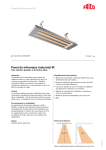
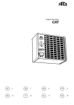
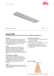
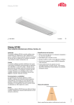
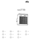
Original instructions
IR3000, IR4500, IR6000
SE .... 8
GB .... 9
NO .... 11
FR .... 13
FI .... 15
NL .... 17
DE .... 19
PL .... 21
RU .... 22
IT
.... 24
IR3000, IR4500, IR6000
Type
L1
[mm]
L2
[mm]
IR3000
600
1125
IR4500
900
1500
IR6000
1200
1875
Minimum
distance
[mm]
2
Ceiling
A
400
Wall, long side of the unit
B
400
Wall, short side of the unit
C
400
Flammable material
D
700
Floor
E
2300
IR3000, IR4500, IR6000
min 400
30˚
30˚
3
IR3000, IR4500, IR6000
Accessories
IRG,
Protection grille
Type
E-nr
(SE)
EL-nr
(NO)
HxWxD
[mm]
IRG3000
85 704 10
54 325 16
869x362x40
IRG4500
85 704 11
54 325 17
1235x362x40
IRG6000
85 704 12
54 325 18
1615x362x40
Controls
Auto
15
15
15
20
10
20
30
FLOOR
LIMIT
25
25
5
30
ROOM
S
SETTING
5
30
25
T10S
TKS16
TDIN
TP8
WEST
6100+
PV
1
4h
2
SP
2h
0
1h
MAN
12
AT
ALM
AUTO
MAN
CBT
KRT1900
S123
CBT
Type
E-nr
(SE)
EL-nr
(NO)
HxWxD
[mm]
T10S
85 809 33
54 911 12
TKS16
85 809 37
54 911 51
TDIN
85 809 48
TP8
EDM61
SSR
Type
EL-nr
(NO)
HxWxD
[mm]
80x80x31
EDM61
54 328 87
48x48x120
80x80x39
SSR30A
54 328 89
103x23x103
54 911 48
90x70x58
SSR50A
54 328 92
94x45x103
85 809 47
54 911 47
87x125x34
SSR70A
54 328 94
94x90x103
KRT1900
85 810 12
54 910 50
165x57x60
S123
19 346 40
54 019 23
72x64x46
CBT
87 511 87
54 312 02
155x87x43
4
IR3000, IR4500, IR6000
Wiring diagrams IR
Internal wiring diagram
IR3000, 4500, 6000
N
400V3~ L1
L2
L3
N
L1
L2
L3
N
L1
L2
L3
Control by thermostat, contactor and switch
230V~
NL
Thermostat
2/3 X
1/3 X
0
X X
X
IR
IR
N
L1
L2
L3
3/3 X
N
L1
L2
L3
L3
L2
400V3N~L1
N
1 2 3
N
L1
L2
L3
N
L1
L2
L3
S123
N L1L2 L3
N L1L2 L3
5
IR3000, IR4500, IR6000
Control by timer
CBT
L N
230V~
1 2 3
L
N
6
N
L1
L2
L3
N
L1
L2
L3
IR
N
L1
L2
L3
IR
N
L1
L2
L3
L3
400V3N~ L2
L1
N
N L1L2 L3
N L1L2 L3
IR3000, IR4500, IR6000
Technical specifications | Industrial infrared heater IR  3
Type
Output stages
Voltage
[kW]
[V]
IR3000
1/2/3
400V3N~*1
IR4500
1.5/3/4.5
400V3N~*1
Amperage
Dimensions
LxHxW
[mm]
Weight
[A]
Max. element
temperature
[°C]
4,3
700
1125x83x358
9.0
6,5
700
1500x83x358
11.1
8,7
700
1875x83x358
IR6000
2/4/6
400V3N~*1
*¹) Can also be connected 400V3~, but then without output stages. With neutral, one element tube at a time can be connected.
[kg]
13.2
Protection class IR: (IP44), splash-proof design.
CE compliant.
7
IR3000, IR4500, IR6000
GB
Assembly and operating instructions
Application
IR is suitabe for total or supplementary
heating of premises with large volume and
high ceilings. It can also be used outdoors
for example on sport arena stands or to keep
loading bays dry and frostless.
Action
The infra-red heater heats up rapidly and
provides additonal heating input immediately
to the area.
Location
For point-heating, at least two infra-red
heaters are placed to ensure that heat is
provided both in front of and behind people
involved. The heaters must be mounted at
least 2 m above people´s heads.
Installation
Suspension brackets can be fitted directly to
the ceiling or wall. The mountings allow the
radiation to be varied 30° in any direction.
Note the permitted installation arrangements
and minimum distances shown on page 2.
In all installations the elements must be
horizontal. It is also possible to suspend the
heaters from cords(minimum Ø 3 mm).
Electrical installation
The apparatus must be permanently
connected. The installation must be carried
out by a qualified technician, and the
appropriate regulations must be followed.
A heat resistant connection cable that can
withstand a constant temperature of at least
90 °C, must be used when connecting the
heater. The connection box contains terminal
blocks for connecting cables with areas up to
16 mm². This makes it possible to connect
several heaters in parallel.
Maintenance
Note! When using for the first time or when
starting up after a long period of disuse, a
small amount of smoke and a slight odour
may occur temporarily, which is completely
normal. When an infra-red installation has
not been in use for some time, the elements
should be ”dried”. Switch on the heaters for
5-10 minutes and then allow them to cool.
The equipment will then be ready for use
again.
If the reflectors are dirty, they can be blastcleaned using compressed air or wiped clean
with a soft cloth.
Residual current circuit breaker (E)
When the installation is protected by means
of a residual current circuit breaker, which
trips when the appliance is connected,
this may be due to moisture in the heating
element. When an appliance containing a
heater element has not been used for a long
period or stored in a damp environment,
moisture can enter the element.
This should not be seen as a fault, but is
simply rectified by connecting the appliance
to the mains supply via a socket without a
safety cut-out, so that the moisture can be
eliminated from the element. The drying
time can vary from a few hours to a few days.
As a preventive measure, the unit should
occasionally be run for a short time when it is
not being used for extended periods of time.
Start up (E)
When the unit is used for the first time or
after a long period of disuse, smoke or odour
may result from dust or dirt that has collected
on the element. This is completely normal
and disappears after a short time.
9
Safety
• For all installations of electrically heated
products should a residual current circuit
breaker 300 mA for fire protection be used.
• The surfaces of the apparatus become hot during use.
• Ensure that there is no flammable material
in direct contact with, or under the heaters
where it could ignite.
• The unit must not be fully or partially
covered with inflammable materials, as
overheating can result in a fire risk!
• The apparatus must not be covered. Overheating can cause a fire-hazard.
• The apparatus must not be fitted
immediately below permanent electrical
wall sockets.
• This product is not designed to be used by children or persons with reduced physical
or mental ability or a lack of experience
and knowledge, unless instruction
regarding the product’s use has been
given by a person with responsibility for
their safety or that this person supervises
operation. Children must be kept under
supervision to ensure they do not play with
the product.
Tel: +46 31 336 86 00
Fax: +46 31 26 28 25
[email protected]
www.frico.se
For latest updated information and information
about your local contact: www.frico.se
Artnr. 204566, 2014-04-08 SÅ/HH/SÄ
Main office
Frico AB
Box 102
SE-433 22 Partille
Sweden