1
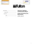
Aurora Universal Commercial Installation and Operators Manual BCG.00530.0AP Rev AB DISCLAIMER The information, specifications, configurations and other technical information regarding the products referenced herein are subject to change without notice. All the statements, technical information and recommendations contained herein are believed to be accurate and reliable but Power-One Corporation makes no representations or warranties with respect to accuracy or completeness of the contents of this Manual. Users must take full responsibility for the application of any products referenced herein. No license whether express, implied, arising by estoppel or otherwise, to any intellectual property rights is granted by this User Guide. TO THE MAXIMUM EXTENT PERMITTED BY LAW, IN NO EVENT SHALL POWERONE BE LIABLE TO BUYER, OR TO ANY PARTY CLAIMING THROUGH OR UNDER BUYER, FOR ANY LOST PROFITS, LOSS OF DATA, INCREASED MANUFACTURING COSTS, LOSS OF GOODWILL, OR FOR ANY INDIRECT, INCIDENTAL, SPECIAL, EXEMPLARY OR CONSEQUENTIAL DAMAGES OF ANY KIND, ARISING OUT OF OR RELATED TO THE USE OF THIS USER GUIDE, OR THE USE OF OR THE INABILITY TO USE ANY PRODUCT REFERENCED HEREIN, EVEN IF POWER-ONE HAS BEEN ADVISED OF THE POSSIBILITY OF SUCH DAMAGES. POWER-ONE’S TOTAL CUMULATIVE LIABILITY SHALL BE LIMITED TO THE AMOUNTS PAID BY BUYER TO POWER-ONE FOR THE PRODUCTS ORDERED PURSUANT TO THE APPLICABLE PURCHASE ORDER. TO THE EXTENT SOME JURISDICTIONS DO NOT ALLOW THE EXCLUSION OR LIMITATION OF INCIDENTAL OR CONSEQUENTIAL DAMAGES, THE ABOVE LIMITATIONS AND EXCLUSIONS MAY NOT APPLY TO BUYER. All rights reserved. No part of this publication may be reproduced, stored in a retrieval system, or transmitted in any form by any means, electronic or mechanical, for any purpose, without the express written consent of Power-One Corporation. Power-One, the Power-One logo, Aurora Universal and Aurora Vision are trademarks or registered trademarks of Power-One Corporation. All other brand or product names may be trademarks or registered trademarks of their respective holders. Copyright© 2011-2012 Power-One Corporation WARRANTY Power-One Corporation (“Seller”) hereby warrants that the product for which this User Guide is written (the “Equipment”) will comply in all material respects with Seller’s published specification for a period of two (2) years from the date of shipment. For any material breach of the foregoing warranty, Seller’s sole and exclusive obligation and buyer’s sole and exclusive remedy for breach of the foregoing warranty shall be, at Seller’s option, to either repair, replace or issue credit for the nonconforming product, provided proof of purchase and written notice of non-conformance are received by Seller within the period noted above and Seller confirms the alleged non-conformity. This warranty shall not apply to Equipment that Seller determines has been, by buyer or otherwise, subject to unauthorized modification, improper installation, misuse, or use for any reason other than electrical power monitoring of solar power equipment. THIS WARRANTY EXTENDS TO BUYER ONLY AND NOT TO BUYER’S CUSTOMERS OR USERS OF BUYER’S PRODUCTS OR SERVICES AND IS IN LIEU OF, AND SELLER EXPRESSLY DISCLAIMS, ALL OTHER WARRANTIES, WHETHER EXPRESSED, IMPLIED, STATUTORY, INCLUDING BUT NOT LIMITED TO ANY WARRANTIES OF MERCHANTABILITY, FITNESS FOR A PARTICULAR PURPOSE, TITLE AND NON-INFRINGEMENT. THIS WARRANTY SHALL NOT BE ENLARGED BY, AND NO OBLIGATION OR LIABILITY SHALL AIRISE OUT OF, SELLER’S RENDERING OF TECHNICAL ADVICE OR SERVICES IN CONNECTION WITH THE DELIVERY OF THE EQUIPMENT. TO THE EXTENT SOME JURISDICTIONS DO NOT ALLOW THE EXCLUSION OF CERTAIN WARRANTIES, SOME OF THE ABOVE EXCLUSIONS MAY NOT APPLY TO BUYER. For further details please go to Seller’s website at: www.power-one.com FCC Compliance Statement This product has been tested and found to comply with the limits for a Class A digital device pursuant to Part 15 of the FCC Rules. These limits are designed to provide reasonable protection against harmful interference when the equipment is operated in a commercial environment. This product generates, uses, and can radiate radio frequency energy and, if not installed and used in accordance with the manufacturer’s instruction manual, may cause harmful interference with radio communications. Operation of this product in a residential area may cause harmful interference, in which case you will be required to correct the interference at your own expense. For the models that contain a cellular router: • The transmitter must not be co-located or operating in conjunction with any other antenna or transmitter. • To comply with FCC RF exposure compliance requirements established in the ANSI C95.1 standards, a separation distance of at least 20 cm must be maintained between the antenna of this device and all persons. • Changes or modifications not expressly approved by the manufacturer could void the user's authority to operate the equipment. This product contains FCC ID: QIPMC75I and IC: 7830A-MC75I. Contents Contents 1 System Overview ............................................................................ 1 2 Aurora Universal Commercial Core Components ............................ 2 2.1 Power Supply ................................................................................................ 2 2.2 Energy Monitoring ........................................................................................ 3 2.2.1 2.2.2 Energy Meter ...................................................................................................................... 3 Current Transducers ............................................................................................................ 3 2.3 Data Logger................................................................................................... 4 2.3.1 2.3.2 2.3.3 Ethernet Ports ..................................................................................................................... 4 Serial Ports .......................................................................................................................... 4 External Device Communication ......................................................................................... 5 2.4 Optional Communications Equipment ........................................................... 6 2.4.1 2.4.2 2.4.3 3 Ethernet Multi-Port Switch ................................................................................................. 6 Cellular Router .................................................................................................................... 6 RS-485 Repeater.................................................................................................................. 6 Installation ..................................................................................... 7 3.1 3.2 3.3 3.4 Before You Go On-Site ................................................................................... 8 Install Enclosure ............................................................................................ 8 Supply Aurora Universal with Power ............................................................. 9 Connect Voltage References and Current Transducers .................................... 9 3.4.1 Current Transducer Installation......................................................................................... 12 3.5 Connect Remote Devices ............................................................................. 12 3.5.1 3.5.2 3.5.3 3.5.4 3.5.5 Remote Device Power Installation .................................................................................... 13 RS-485 Communication Installation .................................................................................. 13 Connect to Power-One Inverters ...................................................................................... 15 RS-485 Device Networking ................................................................................................ 15 Modbus Addressing Policy ................................................................................................ 16 3.6 Other Remote Device Connection Requirements ......................................... 16 3.6.1 3.6.2 3.6.3 3.6.4 3.6.5 Modbus Devices ................................................................................................................ 17 Ethernet Devices ............................................................................................................... 17 Proprietary RS-485 Communication Serial Devices........................................................... 17 RS-485 Mixed-Vendor Environment .................................................................................. 17 Inverter-Specific Requirements......................................................................................... 18 i Power-One • Aurora Universal Commercial Installation and Operators Manual 4 Commissioning............................................................................. 19 4.1 4.2 4.3 4.4 Hardware Installation Check List and Power Up ........................................... 19 Meter Setup ................................................................................................ 20 Connecting to the Internet .......................................................................... 21 Run the Setup Tool ...................................................................................... 22 4.4.1 4.4.2 4.5 4.6 4.7 4.8 4.9 4.10 5 Set a Static IP Address ...................................................................................................... 23 Configure Devices ............................................................................................................. 24 Verify Internet Connectivity......................................................................... 27 Asset Registration ....................................................................................... 27 End-to-End Data Check ................................................................................ 27 Connecting Other Inverters, Connecting Through Other Ports ...................... 28 Installation Checklist and Meter Configuration Form.................................... 28 Maintenance ............................................................................................ 28 Troubleshooting ........................................................................... 29 5.1 Trouble Shooting Guide ............................................................................... 29 5.2 How to Contact Power-One Technical Support ............................................. 31 6 AU Commercial Specifications ...................................................... 32 6.1 6.2 6.3 6.4 6.5 Enclosure .................................................................................................... 32 Terminal Block Specifications....................................................................... 33 Internet Gateway/Data Logger Specifications .............................................. 34 Energy Meter Specifications ........................................................................ 35 Current Transducer Specifications ................................................................ 36 6.5.1 6.5.2 Converter Specifications................................................................................................... 37 Fuse Specifications ........................................................................................................... 37 6.6 Remote Power Wire Sizing .......................................................................... 37 7 Performance Monitoring Form ..................................................... 38 1 System Overview The Aurora Universal is a lightweight solution for remote data acquisition, which enables PV system owners to benefit from advanced energy reports. The data logger collects data from connected devices, such as energy meters, Aurora Smart Combiner DC combiner boxes, inverters and weather stations over the standard Modbus communications protocol, other serial protocols and Ethernet. System performance and energy information are logged into a database on the Information Server, where it can be retrieved and used for analysis via any standard web-browser enabled device by logging into Aurora Vision via the www.auroravision.net website. Aurora Universal in conjunction with Aurora Vision solution brings the following benefits: • Safeguard Your Investment and Maximize Your Return. • Improved Efficiency. • Lower Life Cycle Costs. • Real-time and Historic Data Presented Using Web-based Devices. • Alarm Functions Notify of a Decrease in Production and Device Communication Failure. • Remote Access to all Data Using Internet Technology. The information in this document applies to all Aurora Universal Commercial Models. System Overview Aurora Vision Access to all recorded data is via webbased interface with enhanced productivity tools Aurora Universal data acquisition system providing data logging, multi-vendor communications, and on-site backup Inverter monitoring Energy meter to monitor Energy meter to monitor Aurora Smart instantaneous power, instantaneous power, Combiner for stringgeneration, and generation, and consumption level monitoring of 8, consumption 12, or 16 strings Aurora Environmental to log, store, and retrieve meteorological information The Aurora Universal Commercial comes with Data Logger/Gateway, AC Meter, Power Supply and Terminal Blocks for external connections. RS-485 Repeater, Cell Modem Router and Ethernet Switch are optional and varies per project requirements. The data logger can communicate with connected devices over an RS-485 communications line using the Modbus (RTU) and/or Modbus TCP protocol. The data logger connects to the Local Area Network (LAN) with an Ethernet RJ45 connection (10Base-T). Typically it connects to a Digital Subscriber Line (DSL) or Cable router/gateway to get access to the Internet. The data logger can also be used in cellular wide area networks or dial-up applications. In summary, any kind of Internet Protocol (IP) connection will work. 1 Power-One • Aurora Universal Commercial Installation and Operators Manual 2 Aurora Universal Commercial Core Components Ethernet Switch (optional) Meter Cellular Router (optional) RS-485 ICP Repeater (Stacked 2nd Repeater optional) Data Logger Signal/Earth Ground Connectors Voltage Reference Connectors CT Connectors TB1 TB2 TB3 TB4 24 VDC Connectors TB5 120-240V Power RS-485 Connectors 24VDC Converter The Aurora Universal comes pre-installed in an enclosure and configured for your installation. This handbook describes its different components, how to install the monitoring kit and also serves as a reference. 2.1 Power Supply The Aurora Universal must be supplied with a 120-240VAC 2A hard-wired power source. The AC power source is used to supply control power to the system. NOTE: It is required to supply power from a dedicated 120-240VAC circuit. In some cases, the power source and the energy monitoring voltage taps can be the same. 2 2.2 Energy Monitoring The main purpose of the Aurora Universal is to monitor energy generation or load. There are two components that make that possible: the energy meter and the current transducers (CT). 2.2.1 Energy Meter The AC energy meter is a multifunction sub-meter designed to measure revenue grade electrical energy usage and communicate that information via various communication media. The unit is designed with advanced measurement capabilities, allowing it to achieve high performance accuracy. The energy meter is specified as a 0.2% class energy meter for billing applications. To verify the sub-meter’s performance and calibration, power providers use field test standards to ensure that the unit’s energy measurements are correct. The energy meter is a traceable revenue meter and contains a utility grade test pulse to verify rated accuracy. Veris Energy Meter The Aurora Universal Commercial uses a Veris energy meter, model E51C2. The energy meter will need to be configured in the field for setting serial communication parameters, CT voltage and size and for Service voltage type. Refer to meter setup section for more details. In order to prevent any unwanted changes to the configuration of the meter, the settings are password protected. The meter comes with no password set. It is strongly suggested that you set the meter password and keep the password safe. If the system configuration or CTs are changing please contact Power-One. CAUTION! Be sure to keep your meter password safe. There is no means to recover a lost password and the meter will need to be replaced. For specifications, see Section 6.4 Energy Meter Specifications. 2.2.2 Current Transducers Current transducers, solid or split core, may be provided with the monitoring kit. If current transducers are not provided with the monitoring kit, please refer to 6.5 Current Transducer Specifications to make sure the CTs conform to the required specifications. Do not remove any warning labels or tags from the current transducers. 3 Power-One • Aurora Universal Commercial Installation and Operators Manual 2.3 Data Logger The data logger is an embedded Linux device server developed for industrial use. It is equipped with external connections for two Ethernet, USB, RS-232, and RS-485 connections. The data logger is pre-wired in the Aurora Universal. The Data Logger is located in the middle of the top DIN Rail. Data Logger Ports (Bottom View) RS-485 Screw Terminal RS232 Serial Port (COM2) 2.3.1 Ethernet Ports Eth0 – For Internet Connection Internet Connection – Eth0 The data logger connects to the Aurora Vision server (Aurora Vision solution) over the Internet. The most common scenario is to connect to an existing Local Area Network (LAN) or a dedicated broadband modem, using a standard Ethernet network cable, to the Eth0 port on the data logger. For Models with an Ethernet Switch If your model is equipped with an Ethernet Switch, the Eth0 port will be pre-wired to the switch. Use one of the switch ports to connect to an existing Local Area Network (LAN) or a dedicated broadband modem. The switch can be connected to neighboring Aurora Universals and together these will create a local area network. This local area network needs to be connected to the Internet so that all data loggers can see the internet. For Models with a Cellular Router If your model is equipped with a cellular router, the Eth0 port may not necessarily be connected to the Internet, and may be connected to the Cellular Router. Power-One is not responsible for providing the Internet connection. Configuration Connection – Eth1 The Eth1 port can be used for configuration of the Internet connection and for device communication troubleshooting. 2.3.2 Serial Ports The Aurora Universal Data Logger has two serial ports for connecting to field devices, RS-485 and RS-232. Primary device communication port - RS-485 The primary and secondary device communication port is located on the 6-position terminal block on the data logger. This serial port is dedicated for Modbus RTU communication to Modbus enabled devices. The RS-485 terminals are pre-wired from the 6-position terminal block to a user-accessible terminal block on the Din Rail (TB5) or to a three-way repeater on the upper DIN Rail. See Section 3.5.2 RS-485 Communication Installation for more information. 4 RS-485 Screw Terminal Serial ports – COM1 and COM2 COM1 is not used for device connections. It is only used for factory configuration. COM2 is used for non-standard inverter support. 2.3.3 External Device Communication All Aurora Universals come configured for attachment to Power-One inverters or other Power-One devices. In order to connect other external devices such as inverters from different manufacturers, additional options may need to be purchased from Power-One. Your Aurora Universal is preconfigured for other inverters if the inverter is specified when the Aurora Universal is ordered. In some cases, inverters have to be ordered with communications kits from the inverter manufacturer. Check the Power-One website (http://www.power-one.com/renewableenergy/products/monitoring/aurora-vision) for an up-to-date list of all compatible 3rd party devices. • Power One string and central inverters comes with RS-485 capability and is capable of communicating directly to Aurora Universal • Xantrex GT100, GT250 and GT500 inverters must be ordered with the Modbus RS-485 communication option. • SMA inverters must be ordered with the RS-485 option board and SMA WebBox • PV Powered inverters must be ordered with the Modbus option for three phase inverters and the Ethernet option for single-phase inverters. • Satcon inverters are typically pre-wired for RS-485 Modbus, but it is recommended from the manufacturer to add an RS-485 isolation repeater, such as the ICP-DAS I-7510 Repeater. • Advanced Energy – Solaron inverters must be ordered with the Ethernet communications option. 5 Power-One • Aurora Universal Commercial Installation and Operators Manual 2.4 Optional Communications Equipment Each Aurora Universal Commercial model has unique options for connecting Ethernet and RS-485. 2.4.1 Ethernet Multi-Port Switch The Aurora Universal has an optional multi-port Ethernet Switch. The switch has auto-sensing Ethernet ports, plus an Ethernet port for connection to the data logger. The Ethernet Multi-Port Switch is located within the enclosure at the far right of the upper DIN Rail. The additional Ethernet ports are used to connect local devices that have proximity to the Aurora Universal. LEDs are provided to display the link status and activity of each port, as well as power on/off status. 2.4.2 Cellular Router The Aurora Universal has an optional Cellular Router that can be used instead of a wired Ethernet connection between the data logger and the Internet. Cellular solutions are typically used where external Ethernet connections are not possible. Note that Cellular Routers connect to the Data Logger through Ethernet. The Cellular equipment requires a subscription to a standard cellular provider and a location where cell service is available. The proper data services to communicate with the Cellular equipment and send information to Aurora Vision servers must be set up by the customer. The Cellular Router is located within the enclosure near the far right of the upper DIN Rail. The Cellular router will require drilling a hole to mount the antenna outside the case, typically in the upper right portion of the case. The antenna may be mounted directly on the case or at another location no more than 50 feet from the Aurora Universal case. Make sure to seal the hole made for antenna wire so that the case remains waterproof. It is recommended to use rubber flanges or other waterproof seals such as cable glands. 2.4.3 RS-485 Repeater The Aurora Universal has a one-way or three-way RS-485 repeater for remote device RS-485 connection. The repeater in your system depends on the Aurora Universal Commercial model you have selected. One one-way repeater provides one RS-485 channel (model numbers ending in –1P). One three-way repeater provides three RS-485 channels (model numbers ending in –3P), and two three-way repeaters provide six RS-485 channels. The three-way repeater has three pairs of output RS-485 data connectors (plus and minus) that are pre-wired to the data logger and the RS-485 channels on the lower DIN Rail at TB5. The one-way repeater has only one pair of connectors. Connect all single devices or RS-485 daisy chains to D+ and D- connectors at TB5. The three-way repeater has one RS-485 input channel with a three-way Star Wiring Hub. Each repeater has 3 independent RS-485 output channels. Each output channel on the hub is driven by its own RS-485 driver that can transmit signals along 4,000 ft. (1.2Km) of cable. Note that three-way repeaters include both Hub and Repeater function. Each output channel can be connected to another hub. 6 3 Installation Qualified personnel with appropriate training and experience must perform Aurora Universal installation. Follow standard safety precautions during all procedures. Appropriate personal protection equipment (PPE), such as safety gloves, safety glasses and protective clothing, is recommended. Power-One recommends the use of Ferraz-Shawmut Class CC fuses for the voltage reference (ATMR2/10) power supply (ATMR-2) to prevent hazardous voltage conditions or damage to the equipment. WARNING! During normal operation of the Aurora Universal, dangerous voltages flow through many parts of the system, including: terminals, meter, terminals and any connected CTs (Current Transducers) and PTs (Potential Transformers), all I/O Modules (Inputs and Outputs) and their circuits. All Primary and Secondary circuits can, at times, produce lethal voltages and currents. Avoid contact with any current-carrying surfaces. Do not apply more than the maximum voltage any attached device can withstand. Refer to meter or device labels and to the specifications for all devices before applying voltages. CAUTION! Do not HIPOT/Dielectric test any outputs, inputs, or communications terminals. WARNING! Do not use the meter or any I/O Output Device for primary protection or in an energylimiting capacity. Do not use the meter for applications where failure of the meter may cause harm or death. Do not use the meter for any application where there may be a risk of fire. All meter terminals should be inaccessible after installation. 7 Power-One • Aurora Universal Commercial Installation and Operators Manual 3.1 Before You Go On-Site Make sure you have the following tools and materials before arriving on site. Tools • • • Standard Electrician’s Toolkit Drill capable of penetrating the Aurora Universal enclosure Personal Protective Equipment (Gloves, Goggles, Clothing) Materials and Test Equipment • • • • • Proper Fuses (see recommendations above) Twisted-Pair Wire Ethernet Cable to make Network Connection Laptop Computer with Internet Browser Crossover Ethernet Cable It is also useful to know if you need to perform Asset Registration or final End-to-End Data Checks after physical installation is complete. If so, you will need a username/password to log into the Aurora ADMIN tool and a username/password to log into Aurora Vision. See the Commissioning section for details. 3.2 Install Enclosure Mount the monitoring system enclosure out of direct sunlight in a location where it will not be exposed to continuous water flow, snow and ice build-up, and/or areas of extreme temperature. Install the enclosure using the external enclosure mounting tabs. Drilling holes in the back of the enclosure is not recommended and will void the warranty. CAUTION! The use of UL 514B type conduit fittings are required to maintain the NEMA Type 4/4x rating of the enclosure. The monitoring system enclosure may be mounted in a vertical (where the door opens out) or a horizontal (where the door opens up) orientation. It is recommended to penetrate the enclosure in the bottom only. Remove any metal shavings and treat bare metal with rust inhibitors. Mount the monitoring enclosure in close proximity to the location where the CT will be installed to minimize CT wire length. It is recommended to install the CTs in a location close to the source voltage sensing leads (maximum distance, 100ft.) 8 3.3 Supply Aurora Universal with Power CAUTION! Make sure the service panel (primary circuit) and the monitoring enclosure are deenergized before proceeding with the installation. To provide power to the Aurora Universal, you will need supply a 120-240VAC power source. The line is connected to the terminal TB3-VAC and the neutral connected to the terminal TB3-N. The 120-240VAC power is supplied to the meter and to the power converter in the AU Commercial. Note that meter specifications would allow connection using one of the voltage reference connectors, but the power converter does not allow this type of connection. 3.4 Connect Voltage References and Current Transducers The Aurora Universal Commercial can monitor a generator or load installed with 3 phase Wye or Delta configurations, 208 to 480 Volts. In order to measure electrical energy, current and voltage must be measured. The AC energy meter (Veris) is transducer-rated and requires Current Transducers (CTs) as well as voltage references. CAUTION! Make sure the service panel (primary circuit) and the monitoring enclosure are deenergized before proceeding with the installation. The CT wires need to be terminated before energizing the service panel again. If you cannot terminate them in the monitoring enclosure, short each pair temporarily with a wire nut. Failure to terminate or short the CT wires will destroy the CT and possibly result in fire. 9 Power-One • Aurora Universal Commercial Installation and Operators Manual Voltage reference connections are made to TB-2 and CT leads are connected to TB-1. It is very important to match the phase of the CT to the corresponding voltage reference. If you do not properly match the voltage references to the CTs or do not connect the correct wires to the terminals you will not get accurate data. See the table below for connection points. Aurora Universal Lower Terminal Block Connect CTs Connect Voltage Reference Connect System Power Voltage Reference AU Voltage Measurement Connection Point Current Transducer Leads AU Current Measurement Connection Point Phase A TB-2 - A CT on Phase A, White CT Wire Lead TB-1 A+ CT on Phase A, Black CT Wire Lead TB-1 A- CT on Phase B, White CT Wire Lead TB-1 B+ CT on Phase B, Black CT Wire Lead TB-1 B- CT on Phase C, White CT Wire Lead TB-1 C+ CT on Phase C, Black CT Wire Lead TB-1 C- Phase B Phase C 10 TB-2 - B TB-2 - C Refer to the following connection diagrams showing how voltage reference and CT connections are made for either 3Ø 4 Wire Wye Systems or 3Ø 3 Wire Delta Systems. 11 Power-One • Aurora Universal Commercial Installation and Operators Manual 3.4.1 Current Transducer Installation The CTs can be installed in a service panel or in an appropriate location along the conductor run between the interconnection and the inverter. Leads from the meter to the CT must be less than 100 feet. Mount the Current Transducer around the current carrying conductors with the LOAD towards the Line/Utility side. Terminate the X1 wire (white) on the appropriate TB1 A+, B+, or C+ terminal, and the X2 wire (black) on the appropriate TB1 A-, B-, or C- terminal. Mark each CT wire-pair with appropriate phase identification, Phase A, Phase B, or Phase C. All three CTs must be facing the same direction. If the CTs are facing the wrong direction or different directions, you will not get accurate energy data. Please refer to Section 6.5 Current Transducer Specifications for CT specifications. Use the same color-coding of insulation if you extend the wires from the CTs. The TB1 terminals are rated for stranded copper wire size of #22-#12 AWG. It is possible to put more than one conductor of the same phase through one CT. If the conductors are on the same phase, the current the CT is measuring will be the sum of the two conductors. Make sure the conductors are both the same phase and have current traveling in the same direction. 3.5 Connect Remote Devices The Aurora Universal enclosure can supply power and communication to remote devices such as the Aurora EnvironmentalTM weather station or Aurora Smart Combiner DC monitoring combiner box. Lower DIN Rail, Terminals for 24VDC (TB4) and Modbus RS-485 (TB5) 24VDC 12 RS-485 3.5.1 Remote Device Power Installation Please refer to the remote device’s installation manual for instructions on how to install the remote device. On terminal block TB4, use the top or bottom terminals on the terminal labeled 24+ for the positive conductor and the top or bottom terminals of the terminal labeled 24- for the common or negative conductor for powering remote devices. It is very important to maintain proper polarity, if you mix the positive and common conductors the devices will not work and you risk equipment damage and possible fire. Please refer to Section 6.6 Remote Power Wire Sizing in the Specifications section to properly size the 24 V DC power conductors for the remote devices. 3.5.2 RS-485 Communication Installation The Aurora Universal can communicate with other remote devices such as Aurora Inverters, the Aurora EnvironmentalTM weather station, or Aurora Smart Combiner DC monitoring combiner box. Please refer to the remote device’s installation manual for instructions on how to install the remote device. RS-485 data terminals can accept stranded copper wire of size #12-#22 AWG. Power-One recommends a size of stranded copper #18-#22 AWG twisted pair with shielding and a drain wire; Belden # 1120A cable for 2 conductors or #3106A cable for 3 conductors are recommended. In most applications the third conductor for signal ground is required. The cable must be shielded for reliable communications. Do not run the remote device data cable next to large current carrying conductors. Note that all DIN Rail RS-485 connectors are pre-wired to the repeater and data logger. RS-485 wires use the connectors at TB5 and TB4 (ground) on the lower DIN Rail. All wires come into the connectors straight up and are secured using the small screw facing outward. There are one, three, or six sets (channels) of RS-485 connectors, depending on your Aurora Universal Commercial model. Power-One recommends the convention of using conductors with red insulation for the D (+) and conductors with black insulation for the D (-). Devices will not communicate if you connect the D (+) of one device to the D (-) of another device. RS-485 Connections RS-485 Wire Suggested Wire Color Aurora Universal Connection Point RS-485 Positive Red or Orange D +, TB5 (Right Terminal of Pair) RS-485 Negative Black or Blue D -, TB5 (Left Terminal of Pair) Ground Green or White Signal Ground Connector, TB4 Cable Shield ----- Yellow/Green Earth Ground Connector Three-Wire Beldon #3106A Cable 13 Power-One • Aurora Universal Commercial Installation and Operators Manual AU Commercial Models Number of RS485 Channels Number of RS485 Repeaters Number of Supported Protocols Model Numbers Ending in -1P 2 1 2 Model Numbers Ending in -3P 3 1 2 Model Numbers Ending in -2X3P 6 2 2 The following figure is the DIN Rail for a model with six RS-485 channels viewed from below, showing connection points for a single RS-485 channel. Note that the secondary channel is wired for RS-485. Lower DIN Rail from Below, Showing RS-485 Connection Points Secondary RS-485 Connection Channels (Model Numbers Ending in -2X3P Only) Signal and Earth Ground (Shield) Connections RS-485 Positive RS-485 Negative Other Primary RS-485 Connection Channels (Model Numbers Ending in -3P or 2X3P Only) Connect the RS-485 communication cable to the terminals at the bottom of terminals labeled D+ and D- in terminal block TB5. The primary RS-485 channel(s) are those closest to the back wall of the enclosure. Connect the signal ground wire to the ground connection on TB4. All ground wires should be connected to ground in one location only to avoid ground loops. Note that if all RS-485 devices are getting 24V power from the Aurora Universal, the signal ground wire is not necessary. Connect all RS-485 shield wires to the same yellow/green ground connector on the DIN Rail. The shield wires should be connected to ground in one location only to avoid ground loops. 14 3.5.3 Connect to Power-One Inverters Power-One inverters use a proprietary RS-485 communication interface, and therefore must be daisy-chained to a single set of RS-485 connectors on the DIN Rail. For multiple inverters, each inverter must be manually assigned a different RS-485 address. Refer to the inverter manual(s) for instructions on how to set inverter addresses and exact inverter connection points. It is suggested to connect Power-One inverters through the secondary RS-485 port (forward connectors) on the DIN Rail. Connect Modbus RS-485 devices (such as other meters, weather stations) to the primary RS-485 port (rear connectors). Primary and Secondary connections can be reversed (not mixed!), but the method suggested above matches the default values when commissioning the Aurora Universal. For Power-One model SM 4555, use the Power One Modbus adapter connected to the secondary RS485 interface. 3.5.4 RS-485 Device Networking In a Modbus RS-485 network any one device can be connected to two other devices. If there are more than two remote devices on the Modbus network, they must be wired in a bus topology referred to as a daisy chain. For systems with more than 3 devices and a total cable length of more than 100ft, two termination resistors (120Ω 0.5W) should be used. The resistors must be installed on each endpoint of the daisy chain across Data+ and Data-. Devices typically have a simple jumper to set the termination resistor. Each daisy chain of multiple devices must be connected to a single RS-485 channel at the Aurora Universal. You can connect multiple daisy chains if you have multiple RS-485 channels. You cannot connect more than two devices directly (no daisy chain) to any RS-485 channel on the Aurora Universal. Bus Topology v. Star Topology Bus Topology: OK Star Topology with three-way repeater: OK ICP-DAS I -7513 Star Topology without three-way repreater: NOT ALLOWED A maximum of 32 devices can be connected without another repeater in a single daisy chain. 15 Power-One • Aurora Universal Commercial Installation and Operators Manual 3.5.5 Modbus Addressing Policy Aurora Universals can use the Modbus protocol. The Modbus protocol allows for addresses between 1 and 255. It is suggested that a site have no more than one node per address, even if multiple data loggers or multiple Modbus networks are being used. For larger systems, where unique Modbus addresses are not possible, ensure that each Modbus network is free of duplicate addresses. Please note that your Aurora Universals and add-on products normally are shipped configured to their correct address. It is necessary to configure any equipment that Power-One did not sell. Specifically inverters or energy meters with Modbus RS-485 interfaces need to be configured to the specified Modbus address so the Aurora Universal can communicate with the device. Modbus Addressing Policy Description Modbus Addressing Address range Weather Stations 2–9 Energy Meters (Veris, Shark, SquareD) 10 – 49 Inverters (PowerOne, Satcon, Xantrex GT 100/250) 50 – 99 12 or 16 string DC Combiner Boxes 100-199 8 string DC Combiner Boxes 200-249 Notes These devices require two addresses and should be addressed as base and base+1 For example, if a site has two systems, where the first system consists of an inverter, weather station, two 12-string combiner boxes and an energy meter, and the second system consists of an inverter, two 8-string combiner boxes and an energy meter, the following addressing should be used Modbus Addressing Example System 1 Modbus Address System 2 Modbus Address Weather Station Energy Meter 1 Inverter 1 12-str CB 1 12-str CB 2 2 10 50 100+101 102+103 Energy Meter 2 Inverter 2 8-str CB 1 8-str CB 2 11 51 200 201 3.6 Other Remote Device Connection Requirements If you have purchased monitoring and hosting services for devices not provided by Power-One, such as the inverter direct monitoring, you must configure these devices and possibly the monitoring system to communicate with each other. Check the Power-One website (http://www.powerone.com/renewable-energy/products/monitoring/aurora-vision) for an up-to-date list of all compatible 3rd party devices. 16 3.6.1 Modbus Devices If you have an inverter (Satcon, Xantrex GT three-phase, or other) or energy meter (Shark-100, Square D, Siemens, ION, or other) with a Modbus RS-485 interface or optional Modbus RS-485 interface, configure the Modbus address using our Modbus addressing policy detailed in Section 3.5.5 Modbus Addressing Policy. The Modbus interface of the external device must use 2-wire RS-485 Modbus RTU with 9600 baud and 8-N-1. If there are multiple devices that need to be configured, each device needs to have a unique Modbus address and the first device will have the first address in the series of addresses for the category of that device. If Power-One has sold a device for this system that is in the same category, contact Power-One tech support for the appropriate Modbus address for the device in question. See Section 3.5.5 Modbus Addressing Policy. 3.6.2 Ethernet Devices The Power-One monitoring system can communicate with some third party inverters (PV Powered, Advanced Energy, Xantrex GT and others) and some energy meters (Veris, Square D, Shark, Ion, and others) on the Ethernet network using Modbus TCP. The Internet configuration of the external monitored equipment should be provided by the network administrator of the facility. Please follow the installation manual of the external monitored equipment on how to configure that device to communicate on the Ethernet network. The TCP/IP configuration of the external monitored equipment must be configured so it is accessible from the monitoring system. This means the external monitored equipment and the Power-One monitoring system must be on the same TCP/IP subnet, or routers properly configured to route TCP/IP packets between the monitoring system and the Ethernet connected device. If the external monitored equipment is a PV Powered inverter without the Modbus option, then it should come with an Ethernet option which then would be connected to the Eth1 port on the Aurora Universal’s data logger. If multiple PV Powered inverters are going to be monitored then they should be connected to an Ethernet switch that will also be connected to the Eth1 port on the data logger. 3.6.3 Proprietary RS-485 Communication Serial Devices If you have an inverter such as SMA, or other devices with a proprietary RS-485 communication interface or optional proprietary RS-485 communication interface, configure the address using the addressing policy detailed in the device’s installation/user’s manual. If there are multiple devices please refer to the device’s installation/user’s manual. When the Power-One monitoring system is configured to monitor this type of device there may be a separate device necessary. Contact Power One technical support for more details. 3.6.4 RS-485 Mixed-Vendor Environment All devices in all daisy chain(s) that connect to the primary RS-485 connection channel(s) on the TB5 terminal block of the Aurora Universal must use the same protocol and signal BAUD rate. If you have equipment from the same manufacturer, all equipment should use the same protocol and signal BAUD rate. If you have mixed-vendor equipment, you will need to connect each vendor to the Aurora Universal per the manufacturer’s specifications. This may include connections through Ethernet, primary RS485 port or the secondary RS-485 port. Both the primary and secondary RS-485 ports for the logger are pre-wired to the DIN Rail. Connections through the secondary RS-485 port can use a different 17 Power-One • Aurora Universal Commercial Installation and Operators Manual protocol and/or BAUD rate than connections made through the primary RS-485 port. Contact Power-One Support for more information on connections in a mixed-vendor environment. 3.6.5 Inverter-Specific Requirements In order to use direct inverter communication for other inverter manufacturers, that option has to be purchased from Power-One. The following inverters are supported: Power One Inverters Power One inverters are supported over proprietary RS-485 communication protocol. The Power One inverters must be installed in a separate RS-485 network from the Modbus network. Power One Modbus adaptor uses a different baud rate than other devices. Satcon Inverters Satcon inverters come with a Modbus serial interface, but may need a separate repeater due to their implementation of Modbus. Program the Modbus address in accordance with the Section 3.5.5 Modbus Addressing Policy. Xantrex GT Inverters Xantrex (Schneider Electric) inverters must be ordered with the Modbus RS-485 option. Program the Modbus address in accordance with the Section 3.5.5 Modbus Addressing Policy. AE Solaron Inverters AE Solaron inverters come with a Modbus TCP interface and can be connected to either the Internet side (Eth0) of the data logger or to the LAN side (Eth1). The inverter must be configured with a static IP address. The IP address must be sent to Power-One technical support for proper data logger configuration. AE Solaron communicates with RS-485 Modbus RTU as well. PV Powered Inverters Three phase PV powered inverters must be ordered with the Modbus RS-485 option. Program the Modbus address in accordance with the Section 3.5.5 Modbus Addressing Policy SMA Inverters SMA inverters must be ordered with the SMA RS-485 piggyback card and at least one SMA WebBox per Aurora Universal. The SMA inverters must be installed in a separate RS-485 network from the Modbus network. The SMA RS-485 network is not the same as Modbus and will be connected to a SMA WebBox. Installation notes are available on the Aurora Vision web site. 18 4 Commissioning The following are the major steps required to make sure the system is operational and data is being passed to Aurora Vision servers: • • • Check the hardware installation for completeness and power up the Aurora Universal. Connect the Data Logger to the Internet. Run the Aurora Universal Setup Tool • • If necessary for your network, set up a Static IP Address for the Data Logger. Add and configure Modbus devices that are connected to the Data Logger. Verify that you have a working Internet Connection to the AU Commercial. If not already complete, perform Asset Registration using the Aurora ADMIN tool over the Internet. • Verify end-to-end data transfer using the Aurora Vision web portal. Commissioning is not complete until you have performed the final two steps above over the Internet. However, these two steps do not necessarily need to be performed as part of the on-site hardware installation. If you have a system with several data loggers, please note that each logger has a unique ID and configuration, and are setup for a specific function and location in the plant. 4.1 Hardware Installation Check List and Power Up 1. Check that all terminals are tight, the wires are fully inserted into the proper terminals and there are no frayed conductors shorting out with other conductors. 2. Check the phase of the CTs and voltage references and make sure each phase is properly labeled, terminated, and matched. If the installations of the monitoring system and the PV system are complete and all connections have been double checked, close the service panel and power up the PV system. 3. Close the TB3 single fuse holder, for the system power with the included 2A fuse (Class CC) inserted. The fuse must be 1A for 240 volt systems. 4. With a voltmeter verify that the voltage across TB4-(24+) and TB4-(24- ) is indeed 24 VDC +/10%. 5. Verify that the power LED is green on the data logger. 6. Verify that the energy meter is energized. 7. Close the TB2 fuse holders for the voltage references with the included 0.2A fuses (Class CC) inserted. 8. Set up the Energy Meter to set serial communication and CT parameters. 9. Verify that the energy meter is showing the correct voltages. 10. Start to fill out the Installation Checklist and continue to complete the checklist during the commissioning process. 19 Power-One • Aurora Universal Commercial Installation and Operators Manual 4.2 Meter Setup The following procedures shall be followed to setup the meter during commissioning. Password Setup 1. Press +/ – Arrow until SETUP appears and press Right Arrow to select 2. Default password is 00000. Press +/- Arrow until SPASS appears and press Right Arrow to select 3. Enter new password by pressing +/- Arrow and Right Arrow to move to next character 4. Press Right Arrow until saved. After setting the password, it is very important to save them for your future references. Power-One will not be able to retrieve any lost passwords and will not be liable for replacing a meter in the event a password is lost. CAUTION! Be sure to keep your meter password safe. There is no means to recover a lost password and the meter will need to be replaced. Serial Communication Setup 1. Press +/- Arrow until S COM appears and press Right Arrow to select 2. Set Modbus Address to 010 for first meter using +/- Arrow and press Right Arrow to continue 3. Select and set Baud to 9600 by using +/- Arrow and press Right Arrow to continue 4. Select and set Parity to NONE by using +/- Arrow 5. Press Right Arrow until saved 20 CT Parameters Setup 1. 2. 3. 4. Press +/ – Arrow until SETUP appears and press Right Arrow to select Enter password by using +/- Arrow and press Right Arrow to continue Press +/- Arrow until “S CT” appears and press Right Arrow to continue Select and set “CT V” (CT voltage) by pressing +/- Arrow to match selected CT (normally 0.33 V) and press Right Arrow to continue 5. Set “CT SZ” (CT Size) by pressing +/- Arrow to match selected CT and press Right Arrow to continue 6. Press Right Arrow until saved 4.3 Connecting to the Internet Connect the data logger to the Internet through the local area network or directly. This is done by using a standard Ethernet cable (CAT-5) and connecting it to the Ethernet RJ-45 port marked Eth0 on the front of the data logger. If you have an Ethernet Switch in your AU Commercial model, the Eth0 port will already be connected to the switch. Connect you network cable to an RJ-45 port on the switch. The information below will apply to the port on the switch rather than Eth0. The data logger is by default set to DHCP and will try to acquire its IP-address from the DHCP server on your local network (LAN). Verify that the data logger has an Ethernet connection. The Eth0 LED can be used for detecting network link and network traffic: • Eth0 LED = GREEN = Link • Eth0 LED = GREEN BLINK = Traffic • Eth0 LED= OFF = No network link If no activity is seen on the LEDs, double-check all connections. If it is required to set a static IP for the data logger, your connection will not work until this address is set. Check with your system administrator if a Static IP is required; if so, refer to the section below on setting a Static IP address. If it is necessary to use a wireless network, a wireless network adapter with an Ethernet port is required. Ensure that the wireless connection is operational with a laptop before connecting it to the Eth0 port. The data logger is designed for use on an Ethernet network and must be assigned an IP address (DHCP or static) to make it accessible. The serial number of the data logger is also the MAC address of the Eth0 port, which a network administrator may require. Normally no ports should need to be opened in the network firewall. The data logger will use ports 22 and 443 outbound to transmit the data. Power-One does not provide Internet service or the cables required to connect the Data Logger to the Internet. 21 Power-One • Aurora Universal Commercial Installation and Operators Manual 4.4 Run the Setup Tool The installer must use a laptop with a crossover Ethernet cable to communicate directly to the data logger and run the setup tool. The setup tool has many options and capabilities, but here we will only describe those necessary to get your system up and running. . If your laptop is equipped with a Gigabit Ethernet interface, any Ethernet cable (straight or crossover) will work. Enhancements to the Setup Tool are likely in near the future. Login to the partner portal and check this website https://partner.auroravision.net/display/en/Home for the latest Aurora Universal Setup Tool documentation. 1. Configure the laptop’s Ethernet port to obtain a Dynamic IP address automatically through DHCP; typically, laptops are already configured this way. 2. Connect the crossover Ethernet cable between the secondary Ethernet port marked Eth1 on the data logger and the laptop computer. 3. Open up an Internet browser window on the computer and type in the following URL in the address bar. http://172.17.17.1 4. The following Home page will appear: Select the tabs across the top to perform configuration operations and select one of the ports in the Devices list to set up devices. The icons for the logger in the status area to the right are green. It may take some time for all the icons to turn green. 22 The MAC address (Logger ID) for the Data Logger is displayed at the top of the page. Be sure to write down the MAC address of the Data Logger. The MAC address will be needed later for Asset Registration. 4.4.1 Set a Static IP Address Setting a Static IP is only necessary if required by your network. In most cases you can skip this section. 1. Obtain Static IP address information from your network administrator. 2. Select the Network tab. Set the Type (Network Connection Type) field to Static. The page will allow you to type in the following information: • IP address • Subnet Mask • Gateway • DNS 3. Press Update at the bottom of the page. The Data Logger will restart with its newly configured address. 23 Power-One • Aurora Universal Commercial Installation and Operators Manual 4.4.2 Configure Devices The Devices list on the Home page will show all the different devices connected through all the ports on the Data Logger. It is essential that the devices you set up here match how devices are physically connected to your Data Logger. By default, only the two RS-485 ports are set up. The primary RS-485 port is set to Modbus RTU and the secondary RS-485 is set to Power-One. The default supports hardware connections where all Power-One inverters are attached as an RS-485 daisy chain and connected to the Secondary RS485 port. All Modbus devices (weather stations, meters, combiner boxes, etc.) are daisy chained to the Primary RS-485 port. For the Secondary RS-485 connection, once Power-One inverters are properly addressed and wired in the RS-485 daisy chain, inverters will automatically be discovered and displayed. For the primary RS-485 connection over Modbus RTU, all devices (weather stations, meters, combiner boxes, etc) connected to this port needs to be added. The following procedure gives an example of how to add a device. 1. Go to the Home tab. Click on the Pencil appears: icon across from Devices. The following screen 2. The screen shows the current configuration settings for each port. Select the Plus (+) button on the Primary RS-485 bar to add a device. A window appears to enter device settings. 24 3. Select the correct Device Type from the pull-down menu in the field. Following are Device types that need to be selected for devices supplied with Aurora Commercial: SunSpec Alliance Modbus Interchange - Veris Meter - Aurora Environmental (Entry and Commercial) Power-One String/Subarray Combiner - Aurora Smart Combiners (8, 12 and 16 strings) Following are additional selection options and should be selected only if such devices are supplied or used: Obvius A89DC Solar Current Monitor Power-One PVI-485-MODBUS Adapter Elkor WattsOn Universal Power Transducer Elnet LT Meter Electro Industries Shark100 Meter Advanced Energy Solaron Inverter PVPowered 3 Phase Inverter ION8600/75xx/76xx Meter SM48xx Weather Station SatCon Powergate+ Inverter Schneider ION6200 (EP2) Xantrex GT Inverter on modbus 4. Set the Slave Id field to the Modbus address assigned to this device. This value must correspond to the Modbus address set for the hardware device. 5. Enter a Description to help you identify the device if you need to change configurations later. 6. Click the Add button. 7. The device will be added to the Devices page, listed under the Primary RS-485 port. 25 Power-One • Aurora Universal Commercial Installation and Operators Manual 8. Press the Save icon at the top to commit changes. 9. After making changes, you are reutrned to the Devices page with the status indicators, as shown below. Note that warning symbols show that the device is not reporting correctly. 10. Repeat to add other Modbus devices as needed. 26 4.5 Verify Internet Connectivity 1. Verify that a CAT-5 Ethernet cable is connected between Eth0 and your network. 2. The Data Logger acts as a router. From your laptop connected to Eth1, verify your internet connectivity by opening up an Internet browser window and connecting to an Internet host. 3. Remaining steps for commissioning are performed via the Internet to register the product and check end-to-end communications. Proceed with one of the following steps: a. If you are not responsible for these remaining steps, be sure to pass on the MAC address information to the responsible party. Remove the cable from Eth1 and close the monitoring enclosure. On-site installation is complete. b. If asset registration is already complete, proceed to the section 4.7 Data Check. c. If asset registration is not complete, proceed to the next section 4.6 tion. 4.6 Asset Registration End-to-End Asset Registra- Asset registration is performed via the Aurora ADMIN Web tool. Asset registration assigns the MAC address of your logger to a specific plant in Aurora Vision. Asset registration can be performed before or after the on-site installation is complete. When register a data logger, all the assets (inverters, weather stations, meters, etc.) reporting data to the data logger are also registered. The plant must be created as an asset using Aurora ADMIN before a logger can be assigned and registered. From the Setup Tool, follow the link to the Asset Registration page of Aurora ADMIN. If you are not running the Setup Tool, go to https://admin.auroravision.net/customeradmin. Select Services > Asset Registration and type in the MAC address of the AU Commercial. The Asset Registration page allows you to select the plant that the data will be associated with. Note that use of the Aurora ADMIN tool requires a user name and password with Administrator privileges. Go to https://partner.auroravision.net/display/en/Asset+Registration on the partner portal for help in using the Aurora ADMIN tool for asset registration. 4.7 End-to-End Data Check The last check is to make sure that data is actually being reported and is visible in the Aurora Vision portal. Wait 15 minutes and log on to www.auroravision.net using a web browser on an Internet connected device. Note that use of the Aurora Vision tool requires a user name and password. Within Aurora Vision, go to Asset > Summary page for the plant and open the Device Status panel. Verify that all of the monitored devices are shown and communicating; the Last Reported time should be advancing for all devices. The meter’s power factor should be at least 90%, and its AC phase voltages and currents should match (for 3-phase grid connections). Verify that the energy meter readings agree with the inverter readings. Remove the cable from Eth1 and close the monitoring enclosure. Installation is complete. 27 Power-One • Aurora Universal Commercial Installation and Operators Manual 4.8 Connecting Other Inverters, Connecting Through Other Ports Please contact Power-One Support if you need to connect non-Power-One inverters, or, connect devices through the Serial port or Modbus TCP (Ethernet). 4.9 Installation Checklist and Meter Configuration Form It is recommended that you complete the Performance Monitoring Installation Checklist at the rear of this document and store it for later review. When the monitoring system installation is completed, it may be required to complete a Meter Configuration form, which was sent by the Utility to the person who submitted the rebate application. Make sure the information is legible, correct and complete. Incorrect or incomplete information may result in a delay in the rebate process. 4.10 Maintenance Similar to any electrical device, we recommend regular checkups on the torque of the terminals and making sure the device is clean and dry. Touch up scratched surfaces on the outside of the enclosure to avoid rust. Check fittings for tightness. Lubricate hinges and locks. 28 5 Troubleshooting 5.1 Trouble Shooting Guide 1) Issue: The Data Logger, DC Power Supply, and/or Energy Meter do not power up. a. Using a multi-meter check to see if there is an appropriate AC voltage across the VAC and N terminals of TB3. b. Check the fuse for the monitoring system power at TB3 for its continuity. c. If all of the previous steps do not help this issue, contact Power-One Technical Support. 2) Issue: The power measurements on the energy meter and inverter do not agree. a. Press +/- Arrow until “DEMAND” shows up and press Right Arrow to continue b. Press +/- arrow until “3 PHASE” shows up in Meter’s screen c. Press the Right Arrow until “PF” shows in Meter’s screen d. Is the power factor less than 0.9? If so, the CTs may not be in-phase with the voltage sensing leads, or one or more CT is installed in the wrong direction. De-energize the conductor the CT is measuring and align the CTs with the voltage sensing leads. e. If the power factor is negative then the CTs were installed in the wrong direction. Deenergize the conductor the CT is measuring. Verify that the CTs are facing the wrong direction and either re-install them with the H2 facing towards the line/utility or swap the leads on the CT terminals in the monitoring enclosure. f. If the power factor is above 0.9, check to make sure the meter is setup for the CTs that are being used. g. Press Right Arrow on “SETUP” and enter password h. Press Right Arrow and scroll to “S CT” i. Check “CT V” (CT voltage) and “CT SZ” (CT Size) matches CT rating used. If so then check to make sure all the CTs are facing the same direction. j. If all of the previous steps do not help this issue contact Power-One Technical Support. 3) Issue: Aurora Vision does not show recent information from the monitoring system. a. Verify power source is supplying correct voltage to the Aurora Universal enclosure. b. 24 V DC Power Supply LED = GREEN c. Data Logger POWER LED = GREEN d. Energy Meter display is active. e. Verify that the data logger has a network link, by checking that the Eth0 LED on the data logger is green. If there is no network link then test the Ethernet (Cat5 or Cat6) cable with an appropriate data cable tester and verify the router, switch, or hub is operational. f. Verify that you have a working Internet connection. This can be tested with a laptop by unplugging the Ethernet cable from Eth0 and connecting it to the laptop and testing to see if the laptop can connect to the Internet using the dynamic or static TCP/IP configuration for this network. g. If all of the previous steps are correct restart the data logger by opening the fuse holder for the voltage references, wait 30 seconds and then close the fuse holder for the voltage references. Then wait 20 minutes and check www.auroravision.net for updates. h. If all of the previous steps do not help this issue contact Power-One Support. 29 Power-One • Aurora Universal Commercial Installation and Operators Manual 4) Issue: I cannot connect directly to the web interface on the data logger. a. Verify power source is supplying correct voltage to the data logger by checking that the data logger power LED is green. b. Verify that you have a working Internet crossover cable. One end of the crossover cable should be connected to Eth1 and the other to your computer’s Ethernet port. You should see a link LED illuminated for both the data logger and the computer. c. Verify that the Network settings on the computer. The Network settings for the Ethernet connection should be set to DHCP “Automatically obtain an IP address”. Try to “Repair” the network connection on the computer. d. If all of the previous steps are correct restart the data logger by switching the breaker for the 120V AC power off, wait 30 seconds and then switch it back on again. Also restart your computer. e. Try using a different crossover cable; your cable may be defective. 5) Issue: I do not see all of the remote devices. a. After 3 minutes select refresh on your web browser. b. Close your web browser and reconnect to the data logger’s web page (http://172.17.17.1). c. If the data logger restarts then it received a new configuration which should have all the devices defined. Wait for another three minutes and check the changes. d. If all of the previous steps do not help this issue contact Power-One Technical Support. 6) Issue: I do not see recent data for a remote device. a. Select refresh on your web browser. b. Close your web browser and reconnect to the data logger’s web page (http://172.17.17.1). c. Check to make sure the remote device has power. Check the remote device’s user/installation manual. d. Check to make sure the Modbus communication wires are properly connected. Make sure the data and DC power conductors are not swapped. Make sure D+ and D- from different devices are not connected to each other. Measure the DC Voltage across D+ and Dat both the monitoring enclosure at TB5 and at the data terminals of the remote device. If the measurement is 0 Vdc you have a short in the data wires. If the difference between the two measurements is greater than 3 Vdc then you may have an open circuit. e. If all of the previous steps do not help this issue contact Power-One Technical Support. 30 5.2 How to Contact Power-One Technical Support For most efficient technical support please e-mail Technical Support at [email protected] or call us at +1 877-261-1374. When requesting technical support, please provide the following information: a. Model #. b. Unit serial number. c. Site/project name. d. Problem description. Be prepared to describe the problem you are experiencing including specific details of the application, installation, and any additional pertinent information. In the event that the equipment needs to be returned to the factory for any reason, please call to obtain an RMA# (Return Material Authorization). Do not return items without an RMA# displayed on the outside of the package. If you require an advance replacement to be shipped before the RMA unit has been received by Power-One, you will need to submit a valid purchase order for the replacement unit, referencing the RMA# on the P.O. When we receive the faulty unit, we will credit the cost of the replacement, if it is covered by the warranty. Include a written statement describing the problems. Send the package with shipping prepaid to our factory address. Insure your shipment. Our warranty does not cover damage incurred during transit. 31 Power-One • Aurora Universal Commercial Installation and Operators Manual 6 AU Commercial Specifications 6.1 Enclosure BEL S201606 Enclosure Construction a. b. c. d. e. f. g. h. i. NEMA Type 4-4x-12 / IP-65 enclosure 16 gauge stainless steel Slip hinges enabling cover removal for easier access and mounting Continuously welded and ground smooth seams Galvanized steel panel natural finish (unpainted) 1/4 turn latch Grounding screw on mounting panel Grounding stud welded on inner cover surface ANSI/ASA61 grey polyester Standards j. CSA certified 150359 k. UL listed E109310 l. CE 32 Dimensions m. n. o. p. Height: 20” (508mm) Width: 16” (406.4mm) Depth: 6” (152.2mm) Weight: Approximately 40lbs. (~18kg) depending on options. 6.2 Terminal Block Specifications The Aurora Universal Commercial enclosure provides the following Terminal Blocks for easy field installation. Aurora Universal Terminal Blocks, Lower DIN Rail Allowable Wire Size Terminal Block Allowable Wire Size (AWG) TB1 CT Input Terminals #22 - #12 TB2 Voltage Reference Fuse Holders (A, B, C) Vr Input Terminal #14 - #6 #16 - #6 TB3 VAC Input Fuse Holder VAC Neutral Input Terminal #14 - #6 #16 - #6 TB4 +/- 24 VDC Output Terminals #20 - #10 TB5 Data +/- Output Terminals Ground Terminal #22 - #12 #16 - #6 33 Power-One • Aurora Universal Commercial Installation and Operators Manual 6.3 Internet Gateway/Data Logger Specifications Ethernet Network Connection a. Primary Physical network connection on 10BaseT Ethernet or 100BaseTX Fast Ethernet networks using RJ45 twisted pair cable. (Port name - Eth 0) b. Secondary Physical network connection on 10BaseT Ethernet or 100BaseTX Fast Ethernet, but limited in speed to 12 MBit/s since it is connected through an internal USB port. (Port name Eth 1) Serial Connection a. Two RS-232 serial ports terminated with 9 pin MALE D-SUB connectors. Support baud rates up to 230kbps. b. Two RS-485 serial ports supported on a single screw terminal block. Supports baud rates up to 115200 bps. USB 2.0 Ports a. The USB Ports are currently not used. Hardware a. CPU: Atmel AT91SAM9G20 @ 400MHz b. DRAM: 64 Mbytes c. Flash memory: 256 Mbytes (Normal storage capacity available for data logging is 30 days-worth of data) Power Supply a. Power: 9-24 DC b. Power consumption is typically between 2.8 VA and 3.2 VA. With load on USB bus, power consumption is between 5.0 VA and 7.2 VA Operating Environment a. Temperature: -40°C to +85°C b. Humidity:<80% storage, <85% operating (non-condensing) Dimension a. b. c. d. Height: 1.2“ (31 mm) Width: 5.225” (133 mm) Length: 5.275” (134 mm) Weight: 13 oz. (363 gm.) Compliance The data logger is compliant with both industrial and light industrial/commercial EMC standards for both emission and immunity. Safety a. EN 60950, UL (US version). 34 IP Network Services The data logger is using the following IP Network Services: Direction Service/ Port Protocol Description Out ssh/22 Tcp For remote firmware upgrades, the Data Logger utilize encrypted SSH Remote Login Protocol. To enable upgrades over the Internet, this port has to be opened in any firewall and forwarded to this device. (preferred) Out domain/ 53 Tcp/udp Data Logger must be able to resolve domain names, to ensure scalability and dynamic changes on the Internet. (optional) Out http/443 Tcp As an HTTP client, the Data Logger connects to the Aurora Vision® Information Server for data upload. (mandatory) 6.4 Energy Meter Specifications Measurement Accuracy: Real Power and Energy Reactive Power and Energy Current Voltage Sample Rate Data Update Rate Type of Measurement Input Voltage Characteristics: Measured AC Voltage Metering Over-Range Impedance Frequency Range Input Current Characteristics: CT Scaling Measurement Input Range Impedance IEC 62053-22 Class 0.5S, ANSI C12.20 0.5% IEC 62053-23 Class 2, 2% 0.4% (+0.015% per °C deviation from 25°C) from 5% to 100% of range; 0.8% (+0.015% per °C deviation from 25°C) from 1% to 5% of range 0.4% (+0.015% per °C deviation from 25°C) from 90V L-N to 600VAC L-L 2520 samples per second 1 sec True RMS up to the 21st harmonic 60 Hz One to three phase AC systems Minimum 90VL-N (156VL-L) for stated accuracy; UL Maximums: 600VL-L (347VL-N) CE Maximums: 300VL-N (520VL-L) +20% 2.5 MΩ L-N/5 MΩ L-L 45 to 65 Hz Primary: Adjustable from 5A to 32,000A 0 to 0.333VAC or 0 to 1.0VAC (+20% over-range) 10.6kΩ (1/3 V mode) or 32.1kΩ (1 V mode) 35 Power-One • Aurora Universal Commercial Installation and Operators Manual Control Power: AC DC* Ride Through Time Output: RS-485 Port Mechanical Characteristics: Weight IP Degree of Protection (IEC 60529) Display Characteristics Terminal Block Screw Torque Terminal Block Wire Size Environmental Conditions: Operating Temperature Storage Temperature Humidity Range Altitude of Operation Metering Category: North America CE Dielectric Withstand Conducted and Radiated Emissions Conducted and Radiated Immunity Safety: US and Canada (cULus) Europe (CE) 5VA max.; 90V min. UL Maximums: 600VL-L (347VL-N) CE Maximums: 300VL-N (520VL-L) 3W max.; UL and CE: 125 to 300VDC 100 msec at 120VAC 2-wire, 1200 to 38400 baud, Modbus RTU 0.62 lb. (0.28 kg) IP40 front display; IP20 Meter Back-lit blue LCD 0.37 ft-lb (0.5 N·m) nominal/0.44 ft-lb (0.6 N·m) max. 26 to 14 AWG (0.13 to 2.08 mm2) -30° to 70°C -40° to 85°C <95% RH (non-condensing) 3 km max. CAT III; for distribution systems up to 347 V L-N/600VAC L-L CAT III; for distribution systems up to 300 V L-N/520VAC L-L Per UL 508, EN61010 FCC part 15 Class B, EN55011/EN61000 Class B (residential and light industrial) EN61000 Class A (heavy industrial) UL508 (open type device)/CSA 22.2 No. 14-05 EN61010-1:2001 6.5 Current Transducer Specifications The energy meter included can be accurate with many different CTs the required specifications depend on the specific application, but we recommend using CT’s with the following specifications: a. Voltage output at rated current: .333V b. Accuracy at 10% to 130% of rated current: +/-1% (Note. 1% or better needed to obtain better than 2% accuracy of the whole system) c. Frequency: 50/60 Hz d. Insulation: To meet system voltage e. Leads: Minimum 18AWG twisted pair f. Leads: Maximum distance 100 ft. from meter 36 6.5.1 Converter Specifications g. h. i. j. k. Output Voltage: Output Current: Output Power: Operating Input Voltage: Efficiency: 24.7VDC 5A 124W 85-264VAC, 47-63 Hz, 90-350 VDC 87% Refer to the Power-One W Series Data Sheet, 125, 250 Watt AC-DC and DC-DC DIN-Rail Converters for complete specifications. 6.5.2 Fuse Specifications a. b. c. Voltage Fuse, 120V: Voltage Fuse, 240V: Voltage Reference Fuse: 2A, Class CC (for TB3) 1A, Class CC (for TB3) .2A, Class CC (for TB2) 6.6 Remote Power Wire Sizing If you will be connecting remote devices to the Aurora Universal which require power, like the weather station and the DC combiner box, then this table will help you determine the minimum recommended wire size for the remote device power cable based on the number of devices and the one way distance along the wire run to the farthest remote device. If the remote devices are farther away than 400’ from the Aurora Universal enclosure, a separate 24 VDC power supply must be installed closer to the devices, due to the voltage drop. Remote Device Power Wiring Sizes One way distance along wire run to farthest remote device. Wire size is in AWG and for stranded copper wire Number of Remote Devices 1 to 5 6 to 10 11 to 15 16 to 20 0 to 50' #20 #18 #16 #14 50' to 100' #18 #16 #14 #12 100' to 150' #16 #14 #12 #12 150' to 200' #16 #12 #10 #12 200' to 250' #14 #12 #10 #10 250' to 300' #14 #12 #10 N/A 300' to 350' #12 #10 #10 N/A 350' to 400' #12 #10 #10 N/A 37 Power-One • Aurora Universal Commercial Installation and Operators Manual 7 Performance Monitoring Form 38 Power-One 740 Calle Plano Camarillo, California, 93012 United States Customer Support Phone: 877-261-1374 Customer Support E-mail: [email protected] www.power-one.com © 2011, 2012 Power-One Corporation. Power-One is a registered trademark and Aurora Vision is a trademark of Power-One Corporation. All rights reserved. All other brand or product names are trademarks or registered trademarks of their respective holders. 39