1
890GTB Battery Inverter Product Manual
HA473578U201 Issue 01
Part Number: 890GTB
Software Version: 5.1
2014 Parker EGT, a division of Parker Hannifin Corporation
All rights strictly reserved. No part of this document may be stored in a retrieval system, or transmitted in any form or by any means to persons not employed by a Parker EGT company without written
permission from Parker EGT, a division of Parker Hannifin Corporation. Although every effort has been taken to ensure the accuracy of this document it may be necessary, without notice, to make
amendments or correct omissions. Parker EGT cannot accept responsibility for damage, injury, or expenses resulting therefrom.
WARRANTY Parker EGT warrants the goods against defects in design, materials and workmanship for the period of 24 months from the date of manufacture, or 12 months from the date of delivery
(whichever is the longer period), on the terms detailed in Parker EGT Standard Conditions of Sale IA500504
Parker EGT reserves the right to change the content and product specification without notice.
890GTB Battery Inverter Power Manual HA473578U201 Issue 01
WARNING: USER RESPONSIBILITY
Failure or improper selection improper use of the products described herein or related items can cause death, personal injury, and property damage. This
document and other information from Parker Hannifin Corporation, its subsidiaries and authorized distributors provide product or system options for further
investigation by users having technical expertise.
Users, through their own analysis and testing, are solely responsible for making the final selection of the system and components and assuming that all
performance, endurance, maintenance, safety, and warning requirements of the application are met. Users must analyze all aspects of the application,
follow all applicable industry standards, and follow the information concerning the product in the current catalog and in any other materials provided from
Parker or its subsidiaries or authorized distributors.
To the extent that Parker or its subsidiaries or authorized distributors provide component or system options are based upon data or specifications provided
by the user, the user is responsible for determining that such data and specifications are suitable and sufficient for all applications and reasonably
foreseeable uses of the components or systems.
890GTB Battery Inverter Power Manual HA473578U201 Issue 01
Battery Inverter Manual Table of Contents
CHAPTER 1 SAFETY .................................................................................................................................................................................................................. 1-1
Product Warnings ......................................................................................................................................................................................................................... 1-3
Safety ............................................................................................................................................................................................................................................ 1-4
Risk Assessment ............................................................................................................................................................................................................................ 1-5
Parker Required PPE: .................................................................................................................................................................................................................... 1-9
Approach Boundaries................................................................................................................................................................................................................. 1-10
CHAPTER 2 GETTING STARTED ................................................................................................................................................................................................. 2-1
Typical Related Documentation.................................................................................................................................................................................................... 2-3
Abbreviations / Definitions ........................................................................................................................................................................................................... 2-4
CHAPTER 3 OPERATIONS ......................................................................................................................................................................................................... 3-1
890GT Communications Topology ................................................................................................................................................................................................ 3-2
System Overview .......................................................................................................................................................................................................................... 3-9
SCADA ......................................................................................................................................................................................................................................... 3-34
Starting Up .................................................................................................................................................................................................................................. 3-37
MACHINE STATES ........................................................................................................................................................................................................................ 3-38
Shutting Down ............................................................................................................................................................................................................................ 3-41
CHAPTER 4 TROUBLESHOOTING .............................................................................................................................................................................................. 4-1
WARNING:..................................................................................................................................................................................................................................... 4-2
Typical Enclosure Protection......................................................................................................................................................................................................... 4-3
Typical Inverter Protection ........................................................................................................................................................................................................... 4-3
Typical Table of Symptoms and Possible Causes .......................................................................................................................................................................... 4-4
Typical Equipment-Specific Problems ......................................................................................................................................................................................... 4-13
Typical Level of Training Required to Replace Components ...................................................................................................................................................... 4-16
Typical PLC I/O Associated Fault Codes ...................................................................................................................................................................................... 4-19
System PLC I/O Assignments ...................................................................................................................................................................................................... 4-26
Inverter Keypad Fault List ........................................................................................................................................................................................................... 4-34
COOLING SYSTEM TROUBLESHOOTING ...................................................................................................................................................................................... 4-36
Typical HMI Annunciated Fault Codes ........................................................................................................................................................................................ 4-44
Typical System One-Line Drawing (Shown with 480VAC Grid Connection) ............................................................................................................................... 4-48
890GTB Battery Inverter Power Manual HA473578U201 Issue 01
CHAPTER 5 MAINTENANCE ...................................................................................................................................................................................................... 5-1
WARNING:..................................................................................................................................................................................................................................... 5-2
Preventative Maintenance ........................................................................................................................................................................................................... 5-5
Condenser Maintenance and Service ......................................................................................................................................................................................... 5-16
Procedures .................................................................................................................................................................................................................................. 5-31
OSHA REGULATIONS: .................................................................................................................................................................................................................. 5-39
CHAPTER 6 PPE ....................................................................................................................................................................................................................... 6-1
WARNING:..................................................................................................................................................................................................................................... 6-2
OSHA PPE REGULATIONS: ............................................................................................................................................................................................................. 6-3
Guidelines ..................................................................................................................................................................................................................................... 6-3
Training Requirements.................................................................................................................................................................................................................. 6-4
Protection Requirements .............................................................................................................................................................................................................. 6-4
Personal Protective Equipment Inspection .................................................................................................................................................................................. 6-8
APPENDIX A INVERTER KEYPAD ............................................................................................................................................................................................... A-1
6901 Keypad ................................................................................................................................................................................................................................. A-2
Control Key Definitions ................................................................................................................................................................................................................. A-3
Display Definitions ........................................................................................................................................................................................................................ A-4
The Menu System ......................................................................................................................................................................................................................... A-8
Instructions and Procedures ....................................................................................................................................................................................................... A-12
Inverter Keypad Fault List ........................................................................................................................................................................................................... A-18
APPENDIX B PROGRAMMING .................................................................................................................................................................................................. B-1
Configure the Inverter .................................................................................................................................................................................................................. B-2
Programming with Block Diagrams ............................................................................................................................................................................................... B-3
Grid-Tie Inverter – Typical SunSpec Model Information .............................................................................................................................................................. B-6
Grid-Tie Inverter – Typical SunSpec SCADA available data......................................................................................................................................................... B-13
APPENDIX C CERTIFICATION .................................................................................................................................................................................................... C-1
890GTB Battery Inverter Power Manual HA473578U201 Issue 01
APPENDIX D ASSOCIATED EQUIPMENT MANUALS ................................................................................................................................................................... D-1
Bender Ground Fault Monitor (See Technical Bulletin NAE1012020.pdf) ................................................................................................................................... D-2
National Instruments CompactRIO PLC ........................................................................................................................................................................................ D-6
Parker HPC / HPX Series PowerStation (User Guide HPXUG.pdf)............................................................................................................................................... D-13
Shark Power and Energy Meter (User Guide E149701.pdf) ....................................................................................................................................................... D-19
APPENDIX E TECHNICAL SPECIFICATIONS ................................................................................................................................................................................. E-1
Specifications ................................................................................................................................................................................................................................ E-2
890GTB-2200 Example Efficiency ................................................................................................................................................................................................. E-4
Earthing/Safety Details ............................................................................................................................................................................................................... E-10
Pump Control Module (LA471775U001) .................................................................................................................................................................................... E-11
Pump Control Module ................................................................................................................................................................................................................ E-11
Grid Responses, HVRT and LVRT ................................................................................................................................................................................................. E-15
FqRT ............................................................................................................................................................................................................................................ E-17
Transformer Harmonics .............................................................................................................................................................................................................. E-18
Connector Torque Requirements ............................................................................................................................................................................................... E-19
Typical Spare Parts List ............................................................................................................................................................................................................... E-20
APPENDIX F LIST OF FAULT CODES ........................................................................................................................................................................................... F-1
List of Fault Codes ......................................................................................................................................................................................................................... F-2
890GTB Battery Inverter Power Manual HA473578U201 Issue 01
890GTB Battery Inverter Power Manual HA473578U201 Issue 01
Safety
Chapter 1 Safety
2
3
4
5
Please read these important Safety notes before performing maintenance or operating this equipment.
6
7
Caution
CAUTION notes in the manual warn of danger
to equipment.
8
9
10
11
A
B
Safety Information – Requirements
Safety Information – Product Warnings
Safety
Application Risks
OSHA 29 CFR 1910.269
Arc Flash PPE
Approach Boundaries
C
D
E
890GTB Battery Inverter Power Manual HA473578U201 Issue 01
WARNING
WARNING notes in the manual warn of
danger to personnel.
1-1
1-2 Safety
2
3
Safety Information
Requirements
4
5
6
7
8
9
10
11
A
B
C
D
IMPORTANT Please read this information BEFORE installing the equipment.
Intended Users
This manual is to be made available to all persons who are required to configure or service equipment described herein, or
any other associated operation.
The information given is intended to highlight safety issues, and to enable the user to obtain maximum benefit from the
equipment.
Application Area
The equipment described is intended for use as power conversion in an energy storage system.
Personnel
Installation, operation and maintenance of the equipment should be carried out by qualified personnel. A qualified
person is someone who is technically competent and familiar with all safety information and established safety practices;
with the installation process, operation and maintenance of this equipment; and with all the hazards involved.
Training
Qualified personnel must be trained in Safety-Related Work Practices, Job Hazard Analysis, First Aid and CPR, Arc Flash
Hazards, and PPE Requirements (both classroom and on-the-job training are required in accordance with NFPA 70E
requirements). Retraining is required in intervals not to exceed three years.
E
890GTB Battery Inverter Power Manual HA473578U201 Issue 01
Safety
2
3
Safety Information
Product Warnings
4
5
6
Caution
Risk of electric shock
Earth/Ground
Protective Conductor
Terminal
DANGER! – Ignoring the following may result in injury
8
9
10
11
B
Caution
Refer to documentation
Hazards
7
A
1-3
1. This equipment can endanger life by exposure to high
5. For measurements use only a meter to IEC 61010 (CAT III or higher).
voltages.
Always begin using the highest range. CAT I and CAT II meters must not
2. The equipment must be permanently earthed due to the high
be used on this product.
earth leakage current, and the supplies and loads must be
6. Under normal circumstances the AC and DC Bus should discharge within
connected to an appropriate safety earth.
10 minutes. Use a meter capable of measuring up to 1500 VDC & 600
3. Ensure all incoming supplies are isolated before working on
VAC RMS to confirm that less than 50V is present on the DC BUS and
the equipment. Be aware that there may be more than one
between all power terminals and earth before working on or near the
supply connection to the inverter.
DC Bus.
4. There may still be dangerous voltages present at power
terminals (battery inputs and DC bus) when the inverter is 7. Unless otherwise stated, this product must NOT be dismantled. In the
event of a fault the component must be returned.
stopped.
C
D
E
890GTB Battery Inverter Power Manual HA473578U201 Issue 01
1-4 Safety
2
3
4
5
6
Safety Information
WARNING! – Ignoring the following may result in injury or damage to equipment
Safety
Where there is conflict between EMC and Safety requirements, personnel safety shall always take precedence.
7
Never perform high voltage resistance checks on the wiring without
first disconnecting the inverter from the circuit being tested.
8
Whilst ensuring ventilation is sufficient, provide guarding and /or
additional safety systems to prevent injury or damage to
equipment.
9
10
11
A
B
C
When replacing a component in an application and before
returning to use, it is essential that all user defined parameters for
the product’s operation are correctly installed.
All control and signal terminals are SELV; that is, protected by
double insulation. Ensure all external wiring is rated for the highest
system voltage.
All exposed metalwork in the inverter is protected by basic
insulation and bonded to a safety earth.
Residual-current devices (RCDs) are not recommended for use
with this product; but where their use is mandatory, only Type B
RCDs should be used.
EMC
In a domestic environment this product may cause radio
interference in which case supplementary mitigation measures may
be required.
This equipment contains electrostatic discharge (ESD) sensitive
parts. Observe static control precautions when handling, installing
and servicing this product.
This is a product of the restricted sales distribution class according
to IEC 61800-3. It is designated as “professional equipment” as
defined in EN61000-3-2. Permission of the supply authority shall
be obtained before connection to the low voltage supply.
D
E
890GTB Battery Inverter Power Manual HA473578U201 Issue 01
Safety
2
Safety Information
3
CAUTION!
4
Application Risks
5
The specifications, processes and circuitry described herein are for guidance only and may need to be adapted to the
user’s specific application. We cannot guarantee the suitability of the equipment described in this Manual for individual
applications.
6
7
8
Risk Assessment
Under fault conditions, power loss or unintended operating conditions, the inverter may not operate as intended. In
particular:
9
10
11
A
B
1-5
Stored energy might not discharge to safe levels as quickly as suggested and can still be present even though the
inverter appears to be switched off.
An inverter is a component within a system that may influence its operation or effects under a fault condition.
Consideration must be given to:
Stored energy
Supply disconnects
C
D
E
890GTB Battery Inverter Power Manual HA473578U201 Issue 01
Sequencing logic
Unintended operation
1-6
Safety
Safety Information
WARNING! – Ignoring the following may result in serious injury or damage to equipment
OSHA Electric Power Generation, transmission, and distribution safety standards (29 CFR 1910.269) consideration:
Workers may be exposed to arc flash hazards, electric shocks, and burns that can cause injury and death when making battery or
grid connections. Do not work on connections to the battery container or the grid without proper safety considerations.
Safe work practices as proscribed in OSHA’s Electric Power Generation, Transmission and Distribution Standard must be
implemented and observed. Workers must complete worker training requirements of OSHA’s Electric Power Generation,
Transmission and Distribution Standard, 29 CFR 1910.269.
Dangerous electrical potentials which can result in electrocution and arc flash hazards are present while the
battery container is connected. Workers must pay attention to both battery power conductors and overhead
power lines. While fatal electrocution is the main hazard, other hazards include using tools and equipment
that can contact power lines.
• Look for overhead power lines and buried power line indicators.
• Stay at least 10 feet away from overhead power lines and assume they are energized.
• De-energize and ground lines when working near them.
• Use non-conductive wood or fiberglass ladders when working near power lines.
890GTB Battery Inverter Power Manual HA473578U201 Issue 01
Safety
Safety Information
WARNING! – Ignoring the following may result in serious injury or damage to equipment
Arc Flash and Shock Hazard – Appropriate PPE Required
An Arc Flash Hazard Assessment shall be done to determine the Flash Protection Boundary 1, the incident energy at
the working distance2, and the PPE Requirements.
An Electrical Work Permit is required for any work performed within the Limited Approach Boundary with the
exception of non-contact testing or troubleshooting, or voltage measurement using test probes with a
minimum rating of CAT III, 1000V if appropriate safe work practices and appropriate personal protective
equipment is used.
Category 0 (0-1.2 cal/cm2) – One layer of non-melting / non-flammable clothing
Category 1 (1.21-4.0 cal/cm2) – One layer of fire resistant shirt and pants or coveralls
Category 2 (4.1-8.0 cal/cm2) – 1-2 layers: cotton underwear + fire resistant shirt and pants or coveralls
Category 3 (8.1-25.0 cal/cm2) – 2-3 layers: cotton underwear + fire resistant shirt and pants + coveralls
Category 4 (25.1-40.0 cal/cm2) – 3-4 layers: cotton underwear + fire resistant shirt and pants or coveralls + multilayer flash suit
1
2
Boundary indicates the minimum working distance of the worker’s face and chest
Incident energy measured in calories per square centimetre (cal/cm2)
Incident Energies exceeding 40 cal/cm2 are deemed too hazardous for live work.
890GTB Battery Inverter Power Manual HA473578U201 Issue 01
1-7
1-8
Safety
Example PPE Task Chart:
Table 1-1: Arc Flash and Shock Hazard – Appropriate PPE Required
Tasks Performed on Energized Equipment:
Category
2
1
Boundary
WD - AFB
Insulated
Gloves
Insulated
Tools
Perform infrared thermography and non-contact inspections
0
N
N
Circuit Breaker or Fused Switch operation with covers on
0
N
N
Remove bolted Battery Access Covers
2
18” - 45”
N
N
Work on battery connections
2
18” - 45”
Y
Y
Work on energized 480VAC electrical conductors, including voltage testing
2
18” - 45”
Y
Y
Perform infrared thermography and non-contact inspections inside limited approach (cover off)
3
18” - 60”
N
N
Circuit Breaker or Fused Switch operation with covers off
3
18” - 60”
Y
N
Remove bolted covers or hinged covers for access to energized electrical conductors
3
18” - 60”
N
N
Work on energized electrical conductors, including voltage testing
3
18” - 60”
Y
Y
3
Entry into Enclosure
Not Allowed while energized
1
WD indicates Working Distance (the minimum working distance of the worker’s face and chest), AFB indicates Arc Flash Boundary
OSHA PPE Requirements
3
Voltage source not tied to Inverter Output (Possible RMS value of 1000 Volts if tied to Inverter Output)
2
890GTB Battery Inverter Power Manual HA473578U201 Issue 01
Safety
1-9
Parker Required PPE:
The following list is the minimum Personal Protection Equipment requirements in accordance with NFPA 70E Article 130.7. When working within
the Restricted Approach Boundary, the worker shall wear PPE in accordance with Article 130.4. When working within the Arc Flash Boundary, the
worker shall wear PPE in accordance with Article 130.5. All parts of the body inside the Arc Flash Boundary shall be protected. Any person who
will be required to use PPE will be required to complete training on the proper use of PPE. NFPA 70E Article 320.3(2) prohibits the wear of
conductive objects and jewellery.
Table 1-2: Required PPE Optimum Specifications for HRC2 (8 cal/cm2)
ITEM
Hard Hat
Face Shield
Safety Glasses
Balaclava
Hearing Protection
RATING
NOTE
Type 1, Class E
10 cal/cm2
Must be nonconductive – ANSI/ISEA Z89.1-2009
ASTM F 2178-08
Must be rated for Arc Flash
ANSI Z87.1-2010
2
When working within the Restricted Approach Boundary or the Arc Flash Boundary - ASTM F 1506-10a
10.5 cal/cm
Must be Ear Canal Inserts - OSHA 1910.95
22 dB (A)
Meltable fibers such as acetate, nylon, polyester, polypropylene and spandex are not permitted
Undergarments
Natural Fibers
2
Daily wear - ASTM F 1506-10a
Shirt*
10.5 cal/cm
2
Daily wear - ASTM F 1506-10a
Pants**
10.5 cal/cm
2
When working within the Restricted Approach Boundary or the Arc Flash Boundary - ASTM F 1506-10a
Coveralls***
12.2 cal/cm
When Insulated Gloves are required by task - ASTM D 120-09
Rubber Insulating Gloves
Class 0
2
When Insulated Gloves are required by task (Minimum thickness .03in, unlined, ATPV value > 10 cal/cm )
Leather Protectors
ASTM F 496-06
When Insulated Gloves are required by task (optional)
Cotton Liners
Cotton
Heavy-duty Leather Daily wear - ASTF 2413-05 (must be non-conductive) NO ESD
Steel Toe Boots
Garments worn as outer layers over arc-rated clothing must also be made from arc-rated material (Use as Required)
Outer Layers
When work on live circuits (>50V) is required by task - ASTM F 1505
Tools
1000V-Rated
2
2
*If a shirt is worn as a top layer, it must be rated at 10.5 cal/cm . If it is worn under coveralls rated at 12.2 cal/cm , it may be natural fibers and may be short-sleeved.
2
2
**If pants are worn as a top layer, they must be rated at 10.5 cal/cm . If they are worn under coveralls rated at 12.2 cal/cm , they may be natural fibers.
***Coveralls are the preferred method of protection.
For more information please see Chapter 6 – PPE.
890GTB Battery Inverter Power Manual HA473578U201 Issue 01
1-10
Safety
Safety Information
WARNING! – Ignoring the following may result in serious injury or damage to equipment
Limited Approach Boundary, Restricted Approach Boundary, Prohibited Approach Boundary
Approach Boundaries to Exposed energized Conductors/Parts for qualified employees (NFPA 70E Table 12-1):
For troubleshooting and testing purposes only, qualified persons using proper test equipment and personal protective equipment must adhere to
the boundaries shown below. For adjusting, tightening, calibrating or other work, the circuits must be deenergized, or employees must use
voltage-rated gloves and voltage-rated insulated tools.
For Low Voltage Troubleshooting and Testing only (under 480 volts), a qualified person may penetrate the prohibited approach boundary with
instrument probes, leads, CT’s, etc. The qualified person must wear Class 00 (500 volt-rated) gloves.
Supervisors and employees must ensure that an unqualified person can never come closer to any energized line or part than the Limited Approach
Boundaries
Table 1-3: Approach Boundaries by Voltage
Approach Boundary1,2
Limited Approach
(Exposed movable conductors)
Limited Approach
(Exposed fixed circuit parts)
Restricted Approach
(Shock protection Required + PPE)
Prohibited Approach
(Equivalent to direct contact)
< 50 VAC
< 100 VDC
50-300 VAC
100-300 VDC
301-750 VAC
301-1k VDC
1.1-5 kVDC
751-15 kVAC
5-15 kVDC
Not Specified
10’ – 0”
10’ – 0”
10’ – 0”
10’ – 0”
Not Specified
3’ – 6”
3’ – 6”
5’ – 0”
5’ – 0”
Not Specified
Avoid Contact
1’ – 0”
1’ – 5”
2’ – 2”
Not Specified
Avoid Contact
0’ – 1”
0’ – 4”
0’ – 7”
1
2
Boundary indicates the minimum working distance of the worker’s face and chest
Limited Approach Boundary is 0” with all Access Doors and Panels closed and secured.
890GTB Battery Inverter Power Manual HA473578U201 Issue 01
Safety
1-11
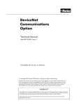
WARNING
ARC FLASH AND SHOCK HAZARD
This unit is powered by batteries
Do not work on this equipment
Without locking out all battery sources
Figure 1-1: Battery Inverter Warning Placard
A variety of battery types may be used in battery enclosures to supply a DC input to the Battery Inverter Enclosure.
Each manufacturer can provide specific Cautions and Warnings for work on and around batteries and for battery
storage which should be observed.
890GTB Battery Inverter Power Manual HA473578U201 Issue 01
1-12 Safety
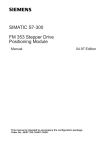
Figure 1-3: Typical Enclosure Access for a 2MW Battery Inverter Enclosure
Table 1-5: Hazard Risk Category with panels open, access to energized circuits:
1
2
3
4
5
6
7
8
Enclosure Access
HRC
HMI Access Door
Inverter Access Door
Capacitor / Inductor Access
Breaker Access Door
DC Input Access
DC Input Access
Inner DC Input Doors
Breaker Access
0
2
4
0
2
2
2
4
WD - AFB
Cal/cm2
Open
18” – 45”
18” – 120”
5.91
32.16
18” – 45”
18” – 45”
18” – 45”
18” – 120”
7.36
7.36
7.36
32.16
Boundary
Note: WD indicates Working Distance (the minimum working distance of the worker’s face and chest), AFB indicates Arc Flash Boundary
Arc Flash Boundary remains in effect regardless of whether Doors and Access Panels are open or closed.
890GTB Battery Inverter Power Manual HA473578U201 Issue 01
Safety
1-13
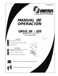
Lifting Precautions
GTB Inverter Lifting Instructions
The GTB Inverter Enclosure can be positioned using either a fork lift or crane. The fork lift tubes along any side of the
enclosure can be used if positioning by a fork lift. The fork lift tubes with a lifting bar and a spreader bar above the
container can be used if positioning by a crane.
Fork lift tubes
Fork lift tubes
Fork lift tubes
Figure 1-4: Fork Lift Tube location on a 2MW Battery Inverter Enclosure
Figure 1-5: Lift Rigging for a 2MW Battery Inverter Enclosure using a crane
890GTB Battery Inverter Power Manual HA473578U201 Issue 01
1-14 Safety
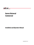
Extreme Arc Flash Hazard
DO NOT WORK ON WHILE ENERGIZED
5.00 cal/cm2 Minimum Flash Hazard / Working Distance 18”
Arc Flash Boundary 45”
Shock Hazard when Cover is Removed
1000 VDC
Limited Approach Boundary
120”
Restricted Approach Boundary
12”
Prohibited Approach Boundary
1”
Equipment: Battery Inverter Enclosure Access 5
PPE Required
2
Min 8 cal/cm2
Date: 12/16/2013
Figure 1-6: Example Arc Flash Label
NFPA 70E 2012 requires warning labels that display the following information: Nominal System Voltage, Arc Flash Boundary, and
at least one of the following: Available Incident Energy and the Corresponding Working Distance, Minimum Arc Rating of
Clothing, Minimum PPE, or Highest HRC of the Equipment.
890GTB Battery Inverter Power Manual HA473578U201 Issue 01
Getting Started
Chapter 2 Getting Started
A few things you should know about this manual.
About this Manual
How the manual is organized
Initial steps
Related Documentation
Abbreviations
890GTB Battery Inverter Power Manual HA473578U201 Issue 01
2-1
2-2
Getting Started
About this Manual
This manual is intended for use by service and maintenance personnel. It assumes reasonable levels of understanding in the
disciplines required to service and maintain this equipment.
Note Please read all Safety information before proceeding with the service, maintenance and operation of this unit.
It is important that you pass this manual on to any new user of this unit.
How the Manual is organized
This manual is organized into chapters, indicated by the numbering on the edge of each page.
The manual is focused on servicing and maintaining the Battery Inverter Enclosure. For more detailed information, refer
to the relevant manufacturer product manual.
Initial Steps
Use the manual to help you plan the following:
Service and Maintenance
Know your requirements:
Training requirements
OSHA Safety conformance
Compliance with Arc Flash requirements
890GTB Battery Inverter Power Manual HA473578U201 Issue 01
Getting Started
2-3
Typical Related Documentation
Several other documents and manuals listed below describe the operation and maintenance of the system, sub-systems, and
Parker EGT components.
These may be referred to throughout this manual.
Battery Inverter Training Guide:
HA473002U201
System Installation Manual:
HG473003U201
Battery Enclosure Manual:
HA473578U211
Firmware Version 5.1 Manual:
HA473746U001
8903/IM, 8903/IP & 8903/PN Ethernet Communications Option
HPC/HPX Series PowerStation User Guide
IPC-IPX Series PowerStation Series Hardware User Manual
System Circuit Diagram:
System One-Line Diagram:
System Communications Diagram:
Control Assembly Panel LA473303U002:
HA500522.pdf
HPXUG.pdf
IPX-IPC USER MANUAL.pdf
HB473000U002
HH473000U002
HI473000U002
HB473303U002
In addition, documentation for key “third party” components is included in Appendix D of this manual.
Bender Ground Fault Technical Bulletin
NAE1012020.pdf
National Instrument CompactRIO cRIO-9072/3/4
374639e.pdf
Shark 200 & 200T Power and Energy Meter Manual
E149701_Shark200 User Manual.pdf
Siemens WL Circuit Breaker Manual
Document Order # CBIM-01001-0504
Stride Industrial Ethernet Switches
sesw8uwt.pdf
SunSpec Alliance Specifications
890GTB Battery Inverter Power Manual HA473578U201 Issue 01
2-4
Getting Started
Abbreviations / Definitions
AC
ANSI
APT
AVR
Converter
DC
Drive
EPO
FR
HRC
HVRT
HMI
HOL
IGBT
Inverter
LOL
LOTO
Alternating Current
American National Standards Institute
Active Power Tracking
Automatic Voltage Regulation
A device that converts one type of energy
to another (AC-AC, AC-DC, DC-DC, or DC-AC)
Direct Current
a generic term for an Adjustable Speed Drive
(ASD) or Variable Speed Drive (VSD)
Emergency Power Off
Flame Resistant
Hazard Risk Category
High Voltage Ride Through
Human Machine Interface
High Operating Limit
Insulated Gate Bipolar Transistor
A converter that changes DC current into
AC current
Low Operating Limit
Lock Out Tag Out
LVRT
MPPT
MPT
MVA
MW
PCM
PCS
PF
Plant
PLC
PPC
PPE
P/S
PV
RPI
SCADA
SP
System
VAR
XML
Low Voltage Ride Through
Maximum Power Point Tracking
Maximum Power Tracking
Mega-Volt Amperes (Apparent Power)
Megawatts (Real Power)
Parallel Control Module
Power Conversion Station (Inverter Transformer Pad)
Power Factor
Power Plant
Programmable Logic Controller
Power Plant Controller
Personal Protection Equipment
Power Supply
Photovoltaic
Requested Packet Interval
Supervisory Control and Data Acquisition
Setpoint
Power Plant Control System
Volt Ampere Reactive (Reactive Power)
Extensible Markup Language
890GTB Battery Inverter Power Manual HA473578U201 Issue 01
Operations
Chapter 3 Operations
System Overview
Starting Up
Running
Shutting Down
890GTB Battery Inverter Power Manual HA473578U201 Issue 01
3-1
3-2 Operations
1
890GT Communications Topology
3
4
SDC (SCADA)
Modbus TCP
5
6
8
9
Parallel IGBT
Stack Controller
SDC (SCADA)
Modbus TCP
Client
890GT
Modbus TCP
Server
890GT
Modbus TCP
Client
Power Quality
Meter
Local
HMI
Figure 3-1: Network Communications
E
890GTB Battery Inverter Power Manual HA473578U201 Issue 01
Operations
3-3
The Parker EGT Battery Inverter Enclosure comprises one Grid-Tie Inverter, fed from one or more battery feeds (typically from 1
Battery Enclosure(s)). The maximum input DC current is 3100 A. The rated AC output power is three-phase, three-wire,
ungrounded, and protected by a 65 kA Sc and up to 3000A rated AC circuit breaker with electronic trip unit. The enclosure is
equipped with access doors, access panels and interior lighting.
3
Designed as a modular component inverter, the Parker EGT Battery Inverter comprises removable modules housed in a rack with
4
front door and rear panel
5
Local control is achieved using the provided selector switch and local HMI.
Remote control is achieved using the provided selector switch and an external SDC (Site Dispatch Controller) / SCADA system.
The DSE 890 Configuration Tool provides access to parameters and configuration for in-depth troubleshooting.
Option Cards can be fitted to the inverter to provide serial communications using several different communication protocols.
6
The inverter is available in different voltage builds. Each build contains inverters with different power ratings. The following
example is for an 890GTB-2206-0CSU0-S400S00, a 2200kVA output Battery Inverter.
Table 3-1: Product Code Structure:
Example Product Code:
890GT
Application:
Solar
Energy Storage
Power Rating:
2200kVA
2100kVA
1950kVA
1800kVA
1750kVA
1700kVA
1600kVA
1500kVA
1450kVA
1400kVA
1250kVA
1200kVA
890GTB Battery Inverter Power Manual HA473578U201 Issue 01
B
-
220
6
-
0C
S
U
0
-
S
4
0
0
S
0
0
8
9
S
B
220
210
195
180
175
170
160
150
145
140
125
120
E
3-4 Operations
Example Product Code:
890GT
Frequency:
50 Hz
60 Hz
DC Connection:
Solar 400 A 16 inputs
Solar 400A 12 inputs
Solar 350A 16 inputs
Solar 350A 12 inputs
Solar 315A 16 inputs
Solar 315A 12 inputs
Solar 250A 16 inputs
Solar 250A 12 inputs
Solar 200A 16 inputs
Solar 200A 12 inputs
Contactor
DC Breaker
AC Connection
Close Coupled
Bottom Entry
Ground
Negative Bus Grounded
Positive Bus Grounded
Ungrounded w/ GF Detector
Ungrounded w/o GF Detector
Enclosure
White (IP65)
Gray (IP65)
White (IP65) - Harsh Environment
Gray (IP65) - Harsh Environment
IP21
Custom
Power Meter
Standard
With Harmonics
with Waveform Capture
B
-
220
6
-
0C
S
U
0
-
S
4
0
0
S
0
0
5
6
1
3
56
52
46
42
36
32
26
22
16
12
0C
0B
4
5
6
8
S
B
9
N
P
G
U
0
1
2
3
4
9
S
H
W
890GTB Battery Inverter Power Manual HA473578U201 Issue 01
E
Operations
Example Product Code:
Communications
Aux Power
Build Standard
Temperature
Advanced Controls & I/O
Other
890GT
None
Ethernet IP - Cu
DNP3 - Cu
EtherCAT - Cu
Modbus TCP - Cu
CanOpen
PROFIBUS
Ethernet IP - Optical
DNP3 - Optical
EtherCAT - Optical
Modbus TCP - Optical
Internally Generated
External 230V single phase
External 400-460Vac 3 phase
External 120/230V and 400-460Vac
UL
IEC
Custom
Standard (-20C to 55C)
Extended Range (-40 to 55C)
Standard
Standard w/analog P/Q
Dynamic controls
Custom
Standard
Custom
B
-
220
6
-
0C
S
U
0
-
S
4
0
0
S
0
0
0
1
2
3
4
5
6
A
B
C
D
3-5
1
3
4
5
6
0
1
2
3
8
0
1
9
9
S
E
0
1
2
9
0
1
E
890GTB Battery Inverter Power Manual HA473578U201 Issue 01
3-6 Operations
1
One-Lines
3
4
5
6
8
9
E
Figure 3-2: Network One Line
890GTB Battery Inverter Power Manual HA473578U201 Issue 01
Operations
3-7
1
3
4
5
6
8
9
Figure 3-3: Power One Line
890GTB Battery Inverter Power Manual HA473578U201 Issue 01
E
3-8 Operations
1
3
4
5
6
8
9
Figure 3-4: AC Power Detail One Line (with filter components)
E
890GTB Battery Inverter Power Manual HA473578U201 Issue 01
Operations
3-9
1
System Overview
Power Flow – Typical Battery Connection
Incoming DC power is supplied to the DC Bus by a 4000A DC Contactor (See Figure 3-5). A maximum DC
input of 3100 A can be accommodated. Both DC connections have an isolation contact. Typical DC bus
potential at the DC Bus tie point ranges from 750 to 1150 VDC but can be lower for lower AC connections.
3
Typical Power Conversion
5
One Parker Grid Tie Inverter (See Figure 3-6) is provided in the Battery Inverter Enclosure. The power
stack includes three, six or nine phase modules (also referred to as CD modules) with one to three
parallel-connected phase modules per phase which are controlled and coordinated by a Parallel Control
Module (PCM). The phase modules are designated by module (“1”, “2”, and “3”) and phase (“U”, “V”,
and “W”). Power connections to the AC output of each phase module are made by bus bars integral to
the power stack frame, utilizing high current plug connectors. Its operation, maintenance, and
programming details are provided in the Grid-Tie Inverter manual (HA473002U001).
4
Figure 3-5: Battery Power Connections
6
8
9
The inverter receives control power (24V DC) from power supplies PS1 (UPS SUPPLY), PS2A and PS2B
(denoted as +24VDC LVRT), and DC auxiliary power from power supply PS3 (OTHER +24V). The LVRT
power supply has an RC network designed to provide Low-Voltage Ride-Through to critical control
functions. PS3 provides +24V for pump, evaporator and non-LVRT functions. PLC Analog inputs,
interface board, and the Therminal strings receive +15 VDC from PS4 and -15 VDC from PS5. Power
supplies are located on LA473303U002 (See Figure 3-7).
Provided on each PCM is a USB port for programming. Parker “DSE Lite” software is available for
programming of the PCM should it ever be necessary to back up or modify the originally provided
program. (It is not recommended that any programming changes be made other than by Parker or a
Parker designated service provider.)
The power stack includes three parallel connected phase modules per phase, which provide conversion
from DC to AC. All modules are easily removed and replaced with minimal manipulation of power wiring.
Quick break no-leak connectors eliminate significant loss of refrigerant when a module is removed.
890GTB Battery Inverter Power Manual HA473578U201 Issue 01
Figure 3-6: Inverter Phase Modules
(3 per phase for a total of 9 modules)
Installed in Power Stack
E
3-10 Operations
1
Power Flow – Grid Feed side
AC power is fed to the grid through the phase modules (See Figure 3-9). The output of each phase module
is connected to individual output phase inductors. Inductors are cooled with liquid cooling circuits and
monitored by integral temperature sensors.
3
The three-phase outputs of the phase inductors are connected in parallel (if more than one phase module)
with each other, the output capacitor filter and then connected to the low voltage winding of the isolation
transformer. The output capacitor filter is provided with contactor control (the contactor is opened by the
PLC when the Inverter is in standby mode). Filter current is monitored by a current transducer on each
phase. The inverter side connection of the isolation transformer is protected by a 3000 amp three pole
circuit breaker. The high voltage windings of an isolation transformer are connected to the grid. The
isolation transformer may have temperature, pressure and oil level sensors.
4
5
6
Auxiliary Power
Multiple options are available for auxiliary power supply to the 890GTB. Please consult factory for specific
needs. Typical configurations include self-generated auxiliary supply or a single-phase UPS Feed
120/230vac and a 3 phase aux power feed 380-480vac to provide power for operation of the PLC, cooling
condenser, blower assemblies, HMI, and other functions within the Battery Inverter Enclosure. The singlephase input is protected by a 6 amp motor overload switch, with branch protection for all sub-circuits.
8
9
Figure 3-7: LA473303U002
The 3-phase auxiliary supply is protected by a 30 amp circuit breaker. Branch protection for the UPS and
auxiliary power for all sub-circuits is located on the LA473303U002 panel.
Figure 3-10: Ethernet Switch
Figure 3-8: Inverter PCM
Figure 3-9: Inverter Phase Modules
E
Figure 3-11: Inverter Circuit Breaker
890GTB Battery Inverter Power Manual HA473578U201 Issue 01
Operations
3-11
Typical Circuit Breaker Operator
A Siemens 3000-amp WL Circuit Breaker Operator (or equivalent) is powered by 24V DC supplied by PS2. The Circuit Breaker Operator controls CB2
(See Figure 3-10), a 3000-Amp Circuit Breaker that feeds the Isolation Transformer. It receives inputs from the Emergency Power Off (EPO) circuit,
and the PLC (Breaker Open, and Breaker Close). The Circuit Breaker Operator provides outputs to the PLC (Breaker Closed, and Breaker Tripped).
Optionally the breaker can be tripped by an external source. Wiring terminals for this option are provided in the control enclosure.
1
3
4
Typical Communications
Within the Battery Inverter Enclosure, an Ethernet network coordinates the inverter stacks, PLC, and HMI devices using CAT5 cable. The inverter
includes a USB port for programming or it can be programmed over Ethernet. Several communications options are available for integration into a
SCADA system.
Cooling
Advanced cooled ratings of the inverter feature a two phase cooling system (See Figure 3-12) which is designed to remove thermal energy losses from
the inverter system and reject them to the ambient surroundings outside of the enclosure. The system uses a positive displacement pump module to
circulate a vaporizable dielectric fluid, refrigerant R134a, through a closed loop circuit. The fluid is in a sub-cooled liquid state as it enters and exits
the pump module.
5
6
8
9
Liquid out of the pump module flows thru up to 19 parallel paths. Nine of these flow paths each contain three cold plates which are in contact with
IGBTs. They are used to transfer heat from the IGBTs to the fluid. Nine more of the parallel flow paths each contain three cooling coils which are in
contact with inductor coils. The cooling coils transfer heat from the inductors to the fluid. The last flow path contains an air cooling coil to manage
internally generated heat.
Other thermal losses in the inverter system are transferred to the air inside of the enclosure via convection. The air is forced across the evaporator
where the heat is transferred to the fluid. As the fluid travels through each flow path it boils as it absorbs heat. The fluid exits each parallel branch
and enters a mixed phase manifold. The flow travels from this manifold to an air cooled condenser where the fluid is condensed back to the subcooled state before it returns back to the pump module.
High heat transfer coefficients, low flow rates and low thermal gradients are achieved by utilizing the two phase cooling cycle.
890GTB Battery Inverter Power Manual HA473578U201 Issue 01
E
3-12 Operations
1
Two-phase Cooling System
3
4
5
6
8
9
Figure 3-12: Two phase cooling system diagram
890GTB Battery Inverter Power Manual HA473578U201 Issue 01
E
Operations
3-13
1
Fluid
The cooling system utilizes refrigerant R134a as the vaporizable dielectric heat transfer fluid is
readily available and commonly used in commercial and industrial systems. R134a has a
favorable latent heat of vaporization values for temperature ranges this system will experience.
It is lower in pressure when compared to other refrigerants. It is non-conductive and non-toxic,
and contains no CFC’s. In the event of an accidental leak or rupture the fluid will vaporize
without harming or leaving residue on any of the devices in the system. 45 lbs. of refrigerant
comes pre-charged with the 890GTB.
3
4
5
Condenser Fans
The two condenser fan motors (See Figure 3-13) are controlled by the Inverter which features
Condenser Status inputs, Pump Control outputs, a Condenser Speed analog output, and a
Refrigerant Level sensor. Fan motor power varies dependant on build variants and receive 380480VAC, 3-phase power directly from the Ziehl FN063-ZIQ. GL.A7P3 Condenser Fan Controllers
protected by CB3. Fans are run at variable speed to extend their life. The 890GTB will continue
to operate with the loss of a single fan.
6
Figure 3-13: Condenser Fans and Condenser Coil
8
9
Evaporator Fans
Four 24-volt Evaporator Fans (See Figure 3-15) are controlled by a Parker Pump Controller (See Figure 3-14) part number LA471775U001 with RTD
feedback from a Return Air Temperature Sensor. Fans are run at variable speed to extend their life. The 890GTB will continue to operate with the
loss of a single fan.
Figure 3-14: LA471775U001 Pump Controller
Figure 3-15: Evaporator Fans
E
890GTB Battery Inverter Power Manual HA473578U201 Issue 01
3-14 Operations
Coolant Pumps
The three-pump module (See Figure 3-16) will consist of
three positive displacement pumps in parallel which are
capable of providing fluid flow at 1800LPH. The 24-volt
Coolant Pumps are controlled by a Parker Pump Controller
part number LA471775U001 with RTD feedback from a
Refrigerant Temperature Sensor. The Pump Controllers are
connected to Control Power (24V DC) from power supply PS3
through a 30 amp fuse.
Figure 3-16: Three-Pump Module
1
3
4
Figure 3-17: Pump Module Component Identification
(Two-Pump Module shown)
A two-pump module (See Figure 3-17) is shown depicting the
components of a typical Pump Module. The addition of the
third pump provides redundancy. The 890GTB will continue
to operate with the loss of a single pump.
5
6
8
9
Ambient Environment Conditions
With the inverter output at 110% the maximum ambient temperature is 40°C with a relative humidity of 50% and a maximum altitude of 1000m. At
100% output the maximum ambient temperature is 50°C with a relative humidity of 50% and a maximum altitude of 1000m.
The inverter will apply a linear power derating of 4% for every °C from 50°C to 55°C. Above 55°C the inverter may shut down.
Altitude Derating is 1.5% for every 100m above 1000m
Enclosure Conditions
The air temperature inside of the enclosure will typically be higher than external ambient temperature during operation. Cooling system components
outside of the enclosure will be exposed to ambient conditions
E
890GTB Battery Inverter Power Manual HA473578U201 Issue 01
Operations
3-15
1
DC Bus Derating
Due to an active grid harmonic mitigation algorithm used by the inverter, the 890GTB may derate operation if the battery voltage is above 1000Vdc.
The derating will be 1% for every 10 volts above 1000Vdc. See figure below for typical derating for temperature and DC bus voltage.
3
4
5
6
8
9
Figure 3-18: Inverter Derating
E
890GTB Battery Inverter Power Manual HA473578U201 Issue 01
3-16 Operations
1
Other Environmental Factors to Consider
The 890GTB may limit output current due to extreme environmental conditions. Sustained winds of over 40MPH that are directed in direct opposition
to the 890GTB condenser fans may result in output current limitation, but wind gusts should have minimal effect on system performance. The
890GTB will derate its output to allow for continued grid operation if high sustained winds are present. Consult the factory if assistance is required for
wind shielding the 890GTB.
Damaging hail or large windborne foreign objects may also damage the enclosure paint system and/or condenser fins. In the event of these extreme
events, the 890GTB should be inspected to ensure integrity of its paint system and health of the condenser fins. Damaged paint can result in
corrosion and permanent damage to the enclosure, damaged condenser fins may cause derated output of the 890GTB.
3
4
5
6
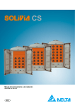
Typical Ground Fault Detection
The BENDER IRDH275 detects ground faults in ungrounded systems by measuring the system's insulation resistance to ground. A ground fault can be
detected before leakage current may even be present. The AGH150W-4 coupling device extends the voltage range to 1760 VDC. When the
measured insulation resistance falls below the set
response value two separately adjustable alarm
contacts can be set to indicate a prewarning and main
warning alarm. The measured value is indicated on the
LCD display or an externally connectable measuring
instrument. A fault storage setting allows the device
to reset automatically or require a manual reset. An
external and internal test/reset can be activated
remotely or on the device. A comprehensive INFO
menu displays additional information such as the
current
leakage
capacitance. The
IRDH275
continuously monitors the equipment ground
connection to ensure proper operation.
Figure 3-19: Bender Ground Fault Detector and coupling device
8
9
E
890GTB Battery Inverter Power Manual HA473578U201 Issue 01
Operations
3-17
1
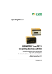
Typical HMI
The Parker IPX10S-D HMI (See Figure 3-20) includes 2 RS-232 ports, 2 10/100BT Ethernet ports, 4 USB ports, and optional PCI expansion slots. Flexible
programming allows for multiple ports to be active simultaneously. The IPX10S-D is powered from 120/220 VAC, 50/60 Hz protected by a 15 amp
FNM fuse.
3
4
5
Figure 3-20: Parker IPX10S-D
Industrial PC / Touchscreen
6
8
9
E
890GTB Battery Inverter Power Manual HA473578U201 Issue 01
3-18 Operations
1
Isolation Transformer
An Isolation Transformer is required to connect the output of the Grid-Tie Inverter to the grid. The Battery Inverter Enclosure has provisions for
accepting two dry contact inputs, a temperature warning indication (180⁰C), and temperature fault indication (200⁰C). Parker can provide specific
transformer requirements upon request, but general requirements include equipping the transformer with an electrostatic shield to minimize EMI
issues and to request a minimum K factor of 4. The inverter is designed for close connection to the transformer via a bus bar throat (standard option)
or can be designed for cable termination in a dedicated entry box.
4
5
Grid Tie Inverter Enclosure
Dedicated Entry Box
3
Battery Enclosure(s)
6
Grid Transformer
8
9
Figure 3-21: Optional Cable Termination
Line Synchronization
The AC Input from the main transformer is connected to the input of the synchronization attenuator LA471892U002 (See
Figure 3-22). This unit provides a low voltage signal to the power stack control module via analog inputs. This card provides
real time phase voltage feedback for synchronization, phasing, and control. The circuit also allows for the execution of power
factor and VAR control. In addition it provides voltage and frequency feedback for grid protection required by IEEE 1547 and
UL 1741.
Figure 3-22: Line Sync Attenuator
E
890GTB Battery Inverter Power Manual HA473578U201 Issue 01
Operations
3-19
1
Typical PLC
Located in the control cabinet, a National Instrument PLC Model Number cRIO-9068 is powered by 24VDC protected by a 5 amp FNM fuse. The PLC
rack includes the following modules:
Slot 01 – Thermocouple input (NI9213) monitors Inductor temperatures and ambient temperatures inside and outside of the inverter.
Slot 02 – 32 Analog inputs (NI9205)
Slot 03 – 32 Digital inputs (NI9425)
Slot 04 – 32 Digital inputs (NI9425)
Slot 05 – 32 Digital outputs (NI9476)
Slot 06 –
Slot 07 –
Slot 08 –
Figure 3-23: National Instruments cRIO-9068 PLC
3
4
5
6
8
9
Figure 3-24: Filter Inductors
(Behind Capacitor Door)
890GTB Battery Inverter Power Manual HA473578U201 Issue 01
Figure 3-25: Filter Capacitors
E
3-20 Operations
1
Typical Power Monitor
A Shark Model Number 200T-60-10-V2-D-INP10 Power Quality Meter (or equivalent) receives a
single-phase AC supply, protected by a 5 amp FNM fuse. The meter analyzes power quality based on
Phase 1 and Phase 3 4000:5 CTs and three-phase 120V AC (Developed from the output AC power,
stepped down through two 150VA single-phase potential transformers (L2 common) protected by 2A
FNQR fuses). The meter provides: Active Power (W), Apparent Power (VA), Frequency (Hz), Phase
Current (A), Power Factor (PF), Reactive Power (VAR), and Voltage (V) measurements with high
performance accuracy.
3
4
5
Figure 3-26: Shark 200 Power Quality Meter
Temperature Sensing
6
8
Temperature sensing is accomplished using networks of thermistor cards daisy chained together and
Thermocouple I/P Modules NI 9213 (See Figure 3-27).
9
The Temperature sensing cards monitor: AC Busbar temperatures (6), Capacitor busbar temperatures in the
Tuned Filter (15), DC Connection Busbar Temperatures (18), Inverter Stack Busbar Temperatures (11), and Filter
Busbar Temperatures (15). For each string, the hottest temperature and its location within the 890GTB will be
available to the user.
Type K Thermocouple sensors monitor: each of the chokes in the Tuned Filter (9), the DC Power supplies (1),
internal ambient temperature (1), external ambient temperature (1), the Main Circuit Breaker Arc Flash Box area
(1), the Surge Suppression panel area (1), Refrigerant Condenser inlet (1), and Refrigerant Condenser outlet (1).
Figure 3-27: Temperature Sensor
E
890GTB Battery Inverter Power Manual HA473578U201 Issue 01
Operations
3-21
1
Typical Enclosure Access Provisions
1
3
2
4
5
5
8
7
6
3
7
4
6
8
8
9
Figure 3-28: Typical 2MW Enclosure Access Provisions
Table 3-3: Typical Enclosure Access:
Enclosure Access
1
2
3
4
5
6
7
8
HMI Access Door
Inverter Access Door
Capacitor / Inductor Access
Breaker Access Door
DC Input Access
DC Input Access
Inner DC Input Access
Breaker Access
890GTB Battery Inverter Power Manual HA473578U201 Issue 01
E
3-22 Operations
1A
1B
1
2
3
4
5
6
8
9
Figure 3-30: ACCESS DOOR #1
ACCESS DOOR#1
(LA473304U001):
HMI, E-STOP, Selector Switches
Figure 3-31: ACCESS DOOR #1 (LA473303U002)
Figure 3-29: ACCESS DOOR #2
ACCESS DOOR#1 (LA473303U002):
ACCESS DOOR#2:
PLC (A1), - T/C Input Modules, Analog Input Modules, Digital Input
Modules, Digital Output Module, Spare PLC Slot, PLC Winford
Breakout Box (A2), Ethernet Port (A7), PLC Adapter Card (A9), Digital
Interface Assembly (A10), Safety Monitoring Relay (EPO), Auxiliary
EPO Relay (EPOA), Heater Relay (K1), LVRT (K2), Control Power Main
(M2), Convenience Outlet (P1), Power Supplies (PS1-5), Fuses
Inverter Power Stack (PCM and Phase
Modules), Pump Controller, Coolant Pumps,
Coolant Reservoir, Sync Attenuator (10A2),
Evaporator Controller (12A2)
890GTB Battery Inverter Power Manual HA473578U201 Issue 01
E
Operations
3-23
1
3
4
5
6
ACCESS COVER #3:
ACCESS COVER #4
AC Filter Capacitors and Contactor
/
ACCESS DOOR #8 (TOP):
Circuit Breakers (CB2, CB3, CB4)
8
9
ACCESS COVER #3:
AC Filter Inductors, Refrigerant
Accumulator, Refrigerant Pump Module
ACCESS COVER #4
/
Strikesorbs, Current Transformers (CT-P1, CT-P2), Fuses (F2, 10F8, 10F9, 10F10, F11, F12, F17,
F18, F19, 10F17, 10F18, 10F19, 10F20, 10F21), Power Meter (A4), Transformer (T1, T3, T4).
Figure 3-32 ACCESS DOORS #3, #4 and #8
890GTB Battery Inverter Power Manual HA473578U201 Issue 01
ACCESS DOOR #8 (BOTTOM):
E
3-24 Operations
1
Figure 3-32A: #7 (Inner Doors) Closed
3
4
5
6
8
9
Figure 3-33: DC Input Locations (ACCESS DOORS #5(Right Side), #6(Left Side) and #7 (Inner Doors))
ACCESS DOOR #5 / #7:
ACCESS DOOR #6 / #7:
DC Input connections (DC+, DC-), Input Temperature Sensors
DC Input Contactors (DC+, DC-), DC Precharge, DC Input
Contactor Temperature Sensors
890GTB Battery Inverter Power Manual HA473578U201 Issue 01
E
Operations
3-25
1
HMI
HOME Screen
The HOME screen displays a lot of data pertaining to the
overall state of the Inverter Enclosure:
The state of the contactors and the Main Circuit
Breaker
The current of each AC output phase, total AC Output
current, and Filter Capacitor phase currents
The Input DC voltage, the AC Output Voltage to the
Grid, and the three AC Output phase-to-phase voltages
The Sync Frequency, Id / Iq Feedback
Kilowatt, kVAR, and Power Factor
The state of the Inverter Stack PCM
R134a Refrigerant Level, Heatsink Temperature, Pump
Inlet Temperature, Pump Speed, Condenser Fan Speed.
The State Machine active state
Temperature Sensing String Temperatures:
o DC Panels
o MCB Busbar
o Filter Busbar
o Cap Door Busbar
o Stack Busbar
Thermocouple readings
3
4
5
6
8
9
HOME
WINDOW
Panel Selection
WATCHDOGS
ALARMS
# Active Alarms
Figure 3-34: HMI HOME Screen
E
890GTB Battery Inverter Power Manual HA473578U201 Issue 01
3-26 Operations
1
LOCAL / REMOTE MODE
Remote mode:
In remote mode, the external SCADA system tells the inverter when to connect / disconnect, and what real and reactive power to
produce / consume.
Primary Local:
Local Remote Selector Switch is the primary means of enabling local control. When in Local, and the inverter on /off switch is moved
into the On position the inverter will automatically close the pre-charge contactors, starting the DC Link charging, after enforcing an
appropriate time delay the inverter will then close the DC main contactor, then the main AC Circuit Breaker, and finally the filter Main
contactor. Upon FM contactor closure, the stack syncs to the line (IGBT Switching) at the LOCALLY entered power points. The real and
reactive powers are entered locally at the inverter HMI – this is the principle difference between Local and Remote mode.
Engineering Development:
A more basic mode of operation can also utilized. When the invert is in the Off state, a local operator can transition the state machine
to the engineering development state. In this state manual operation of the contactors (with safety interlocks enforced) is possible.
Furthermore, in this engineering development state, the selector switches Local/Remote & On/Off are ignored. HMI pushbuttons are
used exclusively.
3
4
5
6
8
9
Engineering development mode is designated for use only by properly trained operators and Parker EGT
engineering and service personnel.
E
890GTB Battery Inverter Power Manual HA473578U201 Issue 01
Operations
3-27
1
WINDOW Selection Screen
3
The WINDOW Selection screen allows the operator to navigate to different screens:
HOME
ALARM Screen
Trend Screen
INVERTER SETUP Screen
PCM CONFIGURATION Screen
Electrical Overview Screen
Miscellaneous Screen
Local Control Screen
SCADA Information Screen
HOME
ALARM Screen
TREND Screen
PCM CONFIGURATION
4
5
6
8
9
SCADA Screen
Figure 3-35: HMI WINDOW Selection Screen
E
890GTB Battery Inverter Power Manual HA473578U201 Issue 01
3-28 Operations
1
SCADA Screen
3
The SCADA screen allows the operator to monitor SCADA communication data.
4
5
6
8
9
Figure 3-36: HMI SCADA Screen
E
890GTB Battery Inverter Power Manual HA473578U201 Issue 01
Operations
3-29
1
PCM CONFIGURATION Screen
The PCM CONFIGURATION screen allows the operator to set the Filter Inductance, Current Loop gains, and DC Volt Demand.
3
4
5
6
8
9
Figure 3-37: HMI PCM CONFIGURATION Screen
E
890GTB Battery Inverter Power Manual HA473578U201 Issue 01
3-30 Operations
1
ALARM Screen
The ALARM screen allows the operator to view, acknowledge, and clear active alarms and to view alarm history.
3
4
5
6
8
9
Figure 3-38: HMI ALARM Screen
E
890GTB Battery Inverter Power Manual HA473578U201 Issue 01
Operations
3-31
1
ALARM CONTROL Screen
The ALARM CONTROL screen allows the operator to Enable and Disable Alarms and Alarm Groups.
3
4
5
6
8
9
Figure 3-39: HMI ALARM CONTROL Screen
E
890GTB Battery Inverter Power Manual HA473578U201 Issue 01
3-32 Operations
1
TREND Screen
The TREND screen allows the operator to chart selected parameters
A value of 100% indicates that the X-axis width
is 10 seconds, 50% indicates 20 seconds, 25%
indicates 40 seconds.
Brings up the screen to select
which data values to chart
3
4
5
Sets the Y-axis
maximum value
6
8
9
Sets the Y-axis
minimum value
Figure 3-40: TREND and PEN SELECT Screen
S
e
E
t
890GTB Battery Inverter Power Manual HA473578U201 Issue 01
s
Operations
3-33
1
Miscellaneous Screen
The MISC screen allows the operator to monitor and adjust selected data
3
4
5
6
8
9
Figure 3-41: HMI MISC Screen
E
890GTB Battery Inverter Power Manual HA473578U201 Issue 01
3-34 Operations
1
SCADA
Typically, a SCADA (Supervisory Control and Data Acquisition) system is used to acquire and store data from the inverter and make stored data available
for users. The SCADA system also provides HMI (Human-Machine Interface) for users to interact with the inverter.
The plant control system performs the real time control of the inverters. It uses the inverter control interface to perform some the following functions:
setting the inverter to various power plant controller modes, setting the limit on the real power of the inverter, regulating the reactive power output of
the inverter or its power factor setting.
The plant controller implements plant level logic and closed loop control schemes to provide fast and reliable plant level control. It uses real-time
commands to inverters to achieve these functions. There is one plant controller per plant that is typically located in a substation and controlling the
conditions at the Point Of Interconnection (POI) or Point of Common Coupling (PCC).
The GTB uses a Sunspec (see: http://www.sunspec.org/) and MESA (see: http://mesastandards.org/)
compliant interface via Modbus TCP as default standard. As part of the joint effort between the MESA
Standards Alliance and the SunSpec Alliance to advance common communication standards for energy
storage devices, MESA adopts the Sunspec model for all Modbus communications inside the energy
storage system, and MESA will lead the SunSpec process for battery communication standards, using
current MESA battery standards as the baseline. The interface can optionally be customized as needed
for other users.
SCADA
3
4
5
6
8
MESA - ESS
9
MESA - ESS
ESS Control System
MESA - Device
Typical Inverter Functions
Some of the typical functions of the enclosure are:
Inverter provides monitoring data to SCADA system through a communications interface
Inverter provides Warnings, Alarms, and Diagnostics for use by the plant SCADA system.
Inverter provides data logging capability of inverter collected/processed data (e.g. fault history,
key process parameters, including trip logs etc.)
The PLC provides 2 discrete inputs (180⁰C and 200⁰C) to monitor transformer temperature.
MESA - Device
MESA - Device
MESA - Device
PCS
Batteries
Power
Meters
Figure 3-42: MESA Interface
MESA standardizes communication and control between the
ESS and SCADA as well as standardizing connections between
ESS devices such as power conversion systems (PCS),
batteries, and power meters.
890GTB Battery Inverter Power Manual HA473578U201 Issue 01
E
Operations
1
Typical Activity between PPC and Inverter Enclosure
PPC
3-35
Inverter
MODEL#1 / 40005x66 - Inverter
MODEL#113 / 40073x60 - Inverter
Feedback
MODEL#120 /TYPE#82 / 40136x26 – VA,
MODEL#121 / 40163x30 – Inverter
Nominal 0.1 – 1s
Update Rate
3
Identity
VAR, PF
Setpoints
Inverter Identity
Currents
Voltages
Power
Temperatures
Power Output Capability
VA Capability
RMS AC Current Capability
Continuous VAR
Minimum PF Capabilities
Nominal Energy Rating
Usable Battery Capacity
Maximum Power
Maximum Voltage
Minimum Voltage
Maximum Reactive Power
Ramp Rate
Minimum PF
Nominal Frequency
5
6
8
9
See page B-6 for more detailed information
Figure 3-43a: PPC/Inverter Interface
890GTB Battery Inverter Power Manual HA473578U201 Issue 01
4
E
3-36 Operations
PPC
1
Inverter
MODEL#122 / 40195x44 - Inverter
Status
MODEL#123 / 40241x24 – Connection
Control
Inverter Status
ECP Connection Status
Lifetime Energy Output
Available VARs
Available Watts
Connection Control
Throttle Enable / Disable
Fixed PF Enable / Disable
% Limit VAR Enable / Disable
See page B-6 for more detailed information
MODEL#64800 / 40627x247 – PLC
I/O
Nominal 0.1 – 1s
Update Rate
PLC Data Exchange
See page B-13 for more detailed information
3
4
5
6
8
9
Figure 3-43b: PPC/Inverter Interface
E
890GTB Battery Inverter Power Manual HA473578U201 Issue 01
Operations
Starting Up
3-37
1
On start-up, if the system responses are determined by the state machine scheme. When power is applied, a brief initialization 3
process is started to restore volatile data changed during runtime, and to configure location, time zone, and communications
parameters. Thereafter, if the On/Off switch is in the OFF position, the system will transition to the OFFLINE state (See the 4
following Simplified Machine State Diagram for a graphical representation of machine state relationships).
5
Start-up Pre-conditions
Inverter Auxiliary power C/B closed.
Inverter subsystems healthy. No faults, no EPO existing.
Start-up
Inverter interior ambient temperature and relative humidity are examined.
If required for temperature or humidity control, heating is enabled.
Pre-charge contactor is closed to ramp up the inverter’s DC link voltage to operating voltage.
Main DC contactors are closed.
AC Main Circuit Breaker closed
Filter Contactor Closed
PCM runs (fires the IGBTs)
6
8
9
E
890GTB Battery Inverter Power Manual HA473578U201 Issue 01
3-38 Operations
1
MACHINE STATES
3
MACHINE STATES:
BOOT
INITIALIZE
ENGINEERING DEV
OFFLINE
DC PRECHARGE
DC CONNECT
STOP FAULT
AC CONNECT
ONLINE LOCAL
ONLINE REMOTE
<01> QUEUE OBTAINED, FGPA INIT, XML RECALL COMPLETE
<11> INITIALIZATION COMPLETE – SS OFF
<12> INITIALIZATION COMPLETE – SS ON
<21> HMI OFF PB
<31> ON SS OR ONLINE REQUEST
<32> HMI ENGDEV PB
<33> STOP FAULT
<41> DC PRECHARGE COMPLETE
<51> DC CONNECT COMPLETE
<61> AC CONNECT COMPLETE - LOCAL
<62> AC CONNECT COMPLETE - REMOTE
<81> OFF SS OR OFFLINE REQUEST
<83> EXIT STANDBY
<111> ENTER STANDBY
4
5
6
8
9
E
890GTB Battery Inverter Power Manual HA473578U201 Issue 01
Operations
3-39
1
Typical Simplified Machine State Diagram:
* EPO, OFF,
PCM FAULT
Ground Fault
STOP FAULT
All power removed
BOOT
* Connection to EPO not shown
<01>
*
1
TRANSITIONS:
<01> QUEUE OBTAINED, FPGA INIT, XML RECALL COMPLETE
<11> INITIALIZATION COMPLETE – SS OFF
<12> INITIALIZATION COMPLETE – SS ON
<21> HMI OFF PB
<31> ON SS OR ONLINE REQUEST
<32> HMI ENGDEV REQUEST
<33> STOP FAULT
<81> OFFLINE REQUEST
3
4
5
6
Initialize
Restore Data from XML
SS Off
8
Engineering Mode
9
<11>
*
OFF - ON
IGBTs Off
DC Disconnect
Main Control Power On
<21>
EngDev Engineering Development
<32>
MANUAL Control
<12>
<81>
<31>
<33>
1
Initially when the Battery Inverter Enclosure is powered up, the INITIALIZE sequence completes and the initial MACHINE STATE is chosen
based on the state of S7 (Inverter OFF/ON) and whether Engineering Mode is selected.
890GTB Battery Inverter Power Manual HA473578U201 Issue 01
E
3-40 Operations
1
* <33> Connection to EPO not shown
<31>
*
<33>
**
<41>
3
STOP
FAULT
DCPC
(Precharge)
<81>
RESET
*
4
Precharge Done
5
*
*
DCConnect
<81>
**
<51>
Connected
*
6
PCM Fault
If auto-reset is successful, operation
state remains the same
If auto-reset attempts are exhausted,
state transitions to STOP FAULT
8
AC CONNECT
<81>
**
<61>
<62>
*
*
Online
LOCAL
<81>
**
TRANSITIONS:
<31> ONLINE REQUEST
<33> STOP FAULT
<41> DC PRECHARGE COMPLETE
<51> DC CONNECT COMPLETE
<61> AC CONNECT COMPLETE - LOCAL
<62> AC CONNECT COMPLETE - REMOTE
<71> LOCAL -> REMOTE
<81> OFFLINE REQUEST
<82> REMOTE -> LOCAL
<83> EXIT STANDBY
<111> ENTER STANDBY
<82>
Online
REMOTE
<81>
**
<111>
<71>
9
<83>
STANDBY
E
890GTB Battery Inverter Power Manual HA473578U201 Issue 01
Operations
3-41
Plant Control Mode
1
When the inverter is under the control of a central Power Plant Controller (PPC), it should adhere to PPC commands and settings.
Stop Inverter
When the system goes to the Stop_Inverter state, the inverter will stop and disconnect the DC connections.
Standby
The purpose of this command is to stop the inverter from producing any power. When the system goes to the Standby state, the inverter will be taken
to the Idle state 0kW, 0kVAR. This will allow fast response should the bit be cleared.
Active Power Control On
The purpose of this command is to set the inverter in active power control mode. In the case when this mode is on, the inverter will limit its maximum
output to the given active power limit (Active Pwr % Limit). The inverter may adhere to a ramp rate limit if so configured to reach the new set point.
Note that no action is necessary if the inverter is already producing less active power limit or the inverter is already turned off for other reasons. When
this mode is turned off, the inverter will continue its normal operation without this constraint.
VAR Control Mode
The purpose of this command is to set the inverter VAR control mode or Power Factor mode (assumed to be default). In the VAR control mode, the
inverter is provided a target for reactive power production. The inverter should produce that reactive power as long as it capable of doing so and it is
within its normal operating limits.
3
4
5
6
8
9
LVRT Event Behaviour
In general, the Inverter LVRT behaviour should take precedence over the commands from the control system. If and when possible the inverter should
maintain the commanded set points (Active and Reactive) after fault removal. If there is a communication loss following an LVRT event or other causes,
and the communications are not re-established within a configurable time period the inverter should revert to default, stand-alone mode of operation.
Stand-Alone Mode
In Stand-Alone mode the Inverter should limit its Active Power generation to the level at the time of transitioning to Stand-Alone mode. The Inverter
should transition to Power Factor control mode. In this mode the Inverter should maintain power factor on its terminals to PF at the time of transition
to Stand-Alone mode. The Inverter should maintain power factor controlling generated reactive power.
E
890GTB Battery Inverter Power Manual HA473578U201 Issue 01
3-42 Operations
1
Shutting Down
To shut the system down, stop the inverter if it is running. Once the inverter is stopped disconnect the battery supplies.
3
4
5
6
8
9
E
890GTB Battery Inverter Power Manual HA473578U201 Issue 01
Operations
3-43
Typical Inverter available data
1
Inverter control module data
1,368 Parameters are defined in the PCM. A complete list of these available parameters can be found in the product manual, HA473002U001
(Appendix D). Furthermore, internal, application specific, numerical quantities can also be made available to the fieldbus. Most typically, these
would be the result of calculations within the VM (virtual machine) function block space.
Power meter data
Any parameter within the power meter can be made available to the fieldbus. A complete list of the available parameters can be found in the
E149701 Shark 200T Power Meter User Manual.
3
4
5
6
Battery Inverter Enclosure controller data
Any parameter within the inverter central controller can be made available to the fieldbus. This includes any point of analog or digital I/O that
is wired to the controller.
Inverter – SCADA available data
8
9
See Appendix B (pages B-6 to B-33) for the Inverter – SCADA available data.
E
890GTB Battery Inverter Power Manual HA473578U201 Issue 01
3-44 Operations
1
3
4
5
6
8
9
E
890GTB Battery Inverter Power Manual HA473578U201 Issue 01
Troubleshooting
4-1
1
Chapter 4 Troubleshooting
The following tables can be used to troubleshoot a loss of function, possibly due to a
tripped circuit breaker or blown fuse. They list the component identifier used in the circuit
diagrams and the type, rating and location of each device.
Warnings
Enclosure Protection
Table of Symptoms and Possible Causes
Equipment-Specific Problems
PLC I/O List and Associated Fault Codes
Inverter Keypad Fault List
HMI Annunciated Fault Codes
3
4
5
6
8
9
E
890GTB Battery Inverter Power Manual HA473578U201 Issue 01
4-2 Troubleshooting
1
3
WARNING:
4
IMPORTANT All electrical work must be done in accordance with local, national, and/or international 5
electrical codes by a qualified electrician.
IMPORTANT WARNING: Battery Strings can produce dangerous electrical voltage levels.
IMPORTANT WARNING: Extreme Arc Flash and Shock Hazards
6
Flash Hazard Boundary 60”
8
Up to 24.46 Cal/cm2 at 18”
9
Class 3 PPE Level (Rated at 25 Cal/cm2) – 2 layers of clothing: cotton underwear + fire
resistant shirt and pants or coveralls + multilayer flash suit, VR gloves-tools, with
appropriate flash hood.
Limited Approach Boundary 120”
Restricted Approach Boundary 12”
Prohibited Approach Boundary 1”
Figure 4-1: Electrical Work Hazard
E
890GTB Battery Inverter Power Manual HA473578U201 Issue 01
Troubleshooting
4-3
1
Typical Enclosure Protection
Function
Power Grid Isolation Transformer
Inverter Isolation from Grid
220V Control Power
220V LVRT Power
120V 3-phase to Power Monitor
AC Surge Suppression
ID
CB1
CB2
CB3
F2
F17, F18, F19
10F8, 10F9, 10F10
Type
Rating
Location
___
WL
HEG
FNM
FNQR
AJT
200
3000
100
30
2
100
External
ACCESS #4 / #8
ACCESS #4 / #8
ACCESS #4
ACCESS #4 / #8
ACCESS #4
Type
Rating
Location
FNM
FNM
FNM
FNM
FNM
FNM
FNM
FNM
FNM
FNM
FNM
FNM
FNM
FNM
4
10
5
5
5
5
2.5
20
20
5
20
20
2.5
5
ACCESS #1
ACCESS #1
ACCESS #1
ACCESS #1
ACCESS #1
ACCESS #1
ACCESS #1
ACCESS #1
ACCESS #1
ACCESS #1
ACCESS #1
ACCESS #1
ACCESS #1
ACCESS #1
Type
Rating
Location
FNQR
AJT
DET
2
200
10
ACCESS #4 / #8
ACCESS #4 / #8
ACCESS #6/#7
LA473303U002 Protection
Function
24VDC EPO Supply
230V Aux Power to Heater control
220V UPS Power for EPO, PLC Outputs
230V Aux Power to LVRT
220V UPS Power to HMI
220V UPS Power to Power Meter
PS2 24VDC LVRT Supply
PS2 24VDC LVRT Supply to Inverter Stack
PS2 24VDC LVRT Supply
PS1 24VDC UPS Supply to EPO and PLC I/O
PS3 24VDC Supply to Pump
PS3 24VDC Supply to Evaporator
PS1 24VDC UPS Supply
PS3 24VDC Supply to non-LVRT
ID
F1
F2
F3
F4
F13
F14
F20
F21
F22
F23
F24
F25
F26
F28
3
4
5
6
8
9
Typical Inverter Protection
Function
3-phase Sync
DC Surge Suppression
DC Precharge
ID
10F17, 10F18, 10F19
10F20, 10F21
10F24, 10F25
WARNING: Internal fuses can only be accessed with AC utility disconnect switches, DC Input disconnects open (deenergized) and Locked Out / Tagged Out.
890GTB Battery Inverter Power Manual HA473578U201 Issue 01
E
4-4 Troubleshooting
1
Typical Table of Symptoms and Possible Causes
3
NOTE: This list is not intended to be an exhaustive list of all possible failures.
See Appendix F for more information and a list of annunciated system faults and warnings
PROBLEM
CB2 Trips
ITEM
Inverter Disconnect Breaker
FUNCTION
10A1 Inverter
POSSIBLE CAUSE(s)
Effect on System
Short Circuit
Shut Down
Overload
Inverter Trips
Rodents / Pests
380-480VAC – 120/220VAC
Control Power Breaker
5
6
EPO Active
CB3 Trips
4
Heater
Transformer T1 Failure
LA473303U001 Assy
Short Circuit / Overload
A1 PLC, PS3-PS5
Rodents / Pests
Shut Down
A4 Shark Energy Meter
Condenser Fan Controls
F1 Blowing
+24V EPO Supply
EPO Relay
Short Circuit /Overload
Shut Down
F2 Blowing
220VAC Supply
Heater
Short Circuit /Overload
Shut Down
F3 Blowing
220VAC UPS Supply
K1, K3, EPOA
Short Circuit /Overload
Shut Down
F4 Blowing
220VAC Supply LVRT
PS2a/b +24VDC LVRT, Inverter
Stack, PLC I/O
Short Circuit / Overload
Shut Down
8
9
No Local Control
F13 Blowing
220VAC A5 HMI
Human-Machine Interface
Short Circuit / Overload
Still able to communicate
over SCADA or laptop
F14 Blowing
220 VAC Shark Energy Meter
Power Quality Meter
F17 - F19 Blowing
Transformer T3, T4
Power Monitor voltage sensor
Short Circuit / Overload
Transformer Failure
Short Circuit / Overload
Keep Running, Lose P and Q close trim, Failure
Annunciated
Keep Running, Failure Annunciated
890GTB Battery Inverter Power Manual HA473578U201 Issue 01
E
Troubleshooting
PROBLEM
ITEM
F20 Blowing
PS2 Branch Protection
F21 Blowing
PS2 Branch Protection
F22 Blowing
PS2 Branch Protection
F23 Blowing
PS1 Branch Protection
F24 Blowing
PS3 Branch Protection
F25 Blowing
PS3 Branch Protection
F26 Blowing
PS1 Branch Protection
F28 Blowing
PS3 Branch Protection
FUNCTION
LVRT Supply OK
PLC Input (DI30)
PS2 24VDC LVRT Supply
for 10A1 (Inverter Stack)
PS2 24VDC LVRT Supply
for PLC I/O and A9
24VDC UPS Supply
for EPO and A9
PS3 24VDC Control Power
For Pump Controller
PS3 24VDC Control Power
for 12A2 (Evaporator)
24VDC UPS Supply
Non-LVRT Supply OK
PLC Input (DI31)
POSSIBLE CAUSE(s)
Effect on System
Short Circuit, Overload
Shut Down
Short Circuit, Overload
Shut Down
Short Circuit, Overload
Shut Down
Short Circuit, Overload
Keep Running
Repair at end of the day
Short Circuit, Overload
Shut Down
Short Circuit, Overload
Keep Running, Failure Annunciated, Likely Trip on
Over Temperature Fault Imminent
Short Circuit, Overload
Keep Running
Repair at end of the day
Short Circuit, Overload1
Shut Down
Keep Running, Failure Annunciated
(ACSTRIKE FAULT)
10F8 - 10F10 Blowing
VR1 – VR4 MOVs
AC Surge Suppression
Voltage Surge
MOV VR1 – VR4 shorted
harmonics (filter failure)
fatigue / loose connection
10F17 – 10F19 Blowing
10A2
Line sync module
Short Circuit, Overload
Inverter would trip
10F20, 10F21 Blowing
VR5, VR6 MOV
DC Surge Suppression
Voltage Surge
MOV VR5 – VR6 shorted
Lose grounding connection to the array, Inverter
would trip
10F24, 10F25 Blowing
Precharge Protection
Precharge Circuit
Short Circuit, Overload
Cannot Restart
4-5
1
3
4
5
6
8
9
E
890GTB Battery Inverter Power Manual HA473578U201 Issue 01
4-6 Troubleshooting
PROBLEM
ITEM
EPO Safety Monitoring Relay
FUNCTION
EPO Tripped
POSSIBLE CAUSE(s)
Component Failure
S4 Depressed
Access Panel / Door Open
Effect on System
Reset EPO
System will not start up
HMI Fault Annunciated
M2
Bus does not Precharge
Precharge connection to DC
bus
PLC A5 Module 5
Digital Output 1 Low
SEE HMI FAULT TABLE (page 4-xx)
Control Power Contactor
DCPC Contactor
Component Failure
connector failure, component
failure
Component Failure
Program Issue
10R1, 10R2
Precharge Resistor
component failure (open)
10F24, 10F25
Precharge Fuse
Fuse Blown
Heater
Heater fails to come on or
doesn’t heat effectively
Fuse failure, signal/contactor
failure, heater element failure
Heater never comes on
Component Failure
PLC A5 Module 5
System takes longer than
normal to start up
No Ride Through
Capability
EPO Trip
Digital Output 18
Operate S3 manually to run equipment
Cannot Start
4
5
6
9
Program Issue
Pump Controller 12A2
Fans on during heat cycle
DCPC
Precharge Contactor
High resistance terminals
Precharge time slightly longer, Slight power loss during
Precharge
D1, R1, C1, C2
Ride Through Drop Out Delay
Component Failure
Shut Down
EPO Switch
Component Failure
Switch Depressed
Main Access Door
Filter Access Door
DC Connection Access Door
DC Contactor Access Door
Component Failure
Switch Activated
EPOA Relay
Component Failure
Relay Not Activated
EPO Safety Monitoring Relay
3
8
Unable to manage condensation
K3 Failure
1
Loss of efficiency, shorten fan life
Shut Down
E
890GTB Battery Inverter Power Manual HA473578U201 Issue 01
Troubleshooting
PROBLEM
ITEM
EPO Safety Monitoring Relay
EPO will not reset
Inverter 10A-1,
Digital Input 7 Low
EPO Safety Monitoring Relay
FUNCTION
POSSIBLE CAUSE(s)
4-7
Effect on System
S8 – S12, both channels must
close within 30 mS to reset
the Safety Relay
EPO Reset Switch
Switch S5 Fails to Close
EPO Status
Component Failure
EPO Safety Monitoring Relay
Shut Down
IGBTs ON when System Faults
1
3
4
5
Component Failure
Contactor contacts degrade
6
Bender
AC Connection Points, HighVoltage Connections
Short Phase-to-Ground
Structural Damage
Water Damage
Rodents / Pests
PLC Detects Ground Fault, Shut Down
Lose grounding connection to the array,
Inverter would trip
8
Fuse Indicator
False Indication
Component Failure
Inverter would trip
9
Bender Ground Fault Monitor
False Indication
Component Failure
Noise
Ground Fault Trip
DCB+, DCB-
DC Contactor
welded power contacts
DCPC
Precharge Contactor
welded contacts
Ground Fault
Annunciation Failure
10F21, 10F22 Fuse Indication
Malfunction
(Remains Closed)
Surge Fuse Annunciation
Failure
10F8, 10F9,10 F10, 10F21, or
10F22 Fuse Indication
Inverter Trip
Inverter 10A-1
EPO does not trip
Inverter 10A-1,
EPO Status
Digital Input 7 High
Ground Fault
(10F21, 10F22 not blown)
Sporadic Nuisance Ground
Fault Trips
DC Bus remains
connected to DC Inputs
DC Bus remains connected to the Battery Feed. Inverter would
trip
No indication Fuse is Open
Component Failure
False Open Indication
DC Input becomes ungrounded Significant noise relative to
ground on DC Inputs.
Keep Running, Failure Annunciated
Component Failure
Malfunction (Remains Closed)
No indication Fuse is Open
SEE INVERTER FAULT TABLE (page A-18)
E
890GTB Battery Inverter Power Manual HA473578U201 Issue 01
4-8 Troubleshooting
PROBLEM
ITEM
FUNCTION
Overheating
Imbalanced Current
Effect on System
L1, L2, L3
AC Connection Points
Corrosion
Shut Down
FM1, FM2, FM3
Ambient Temperature
High – Overheating
Loss of Power
L21, L22, L23
L31, L32, L33
L41, L42, L43
Filter Inductors
3
4
Harmonics (filter failure)
5
Component Failure (Open)
Current Sharing Fault
1
Loose connection
Overcurrent Trip
Current Imbalance
POSSIBLE CAUSE(s)
Degradation of Functions
Current Sharing Fault
6
Keep Running
Repair at end of the day
8
Shut Down
9
Shorted Turns
PS1
+24VDC UPS Supply Power
Component Failure
PS2a, PS2b Primary
+24VDC LVRT Supply
K2, PS2, PS3, T1 Component
Failure
Loss of Control Power
PS3 Primary
+24VDC Cooling Power Supply
Short Circuit /Overload
Power Loss
Fuse, component or wiring
failure
Ethernet Failure
Noise, component or cable
failure
FM1, FM2, FM3
Filter Contactor Failure
Contactor not closing
Cannot trim output KW
CT Failure
CTP1, CTP2 Open
Cannot trim output KVAR
PT Failure
F17,F18,F19,T3,T4 Open
Battery Container
Loss of DC Input
Failure in DC Supply
DCB
DC Contactor fails to close
Component failure
Shark Meter
Loss of efficiency
Lower power output
Keep Running, Failure Annunciated
E
890GTB Battery Inverter Power Manual HA473578U201 Issue 01
Troubleshooting
PROBLEM
ITEM
Inverter 10A-1
FUNCTION
POSSIBLE CAUSE(s)
line input data (Voltage)
loss or distortion of signal
10A2
Inverter Sync Attenuator
Component Failure
10F1, 10F2, 10F3
Line Sync Input Fuses
Short Circuit, Overload
Cannot trim output KW
CT-P1, CT-P2
CT Failure
Cannot trim output KVAR
F17,F18,F19,T3,T4
PT Failure
Failure to sync to grid
Analog Input 1, 2, 3
4-9
Effect on System
Inverter would trip
Component failure (open)
Keep Running, Failure Annunciated (still achieve 90%)
Condenser fan not
running at correct speed
Inverter 10A-1
Digital Output 4,5
Inverter 10A-1
Digital Output 4,5
Keep Running, Loss of cooling capacity, Failure Annunciated –
Possible shutdown on Over Temp
component failure, wiring
failure
condenser fan run signals on
all the time
component failure
Keep Running
Wrong speed commanded
Component Failure
Program Issue
Lower Ambient Temperature, Shorten fan life
Digital Output 14 & 15 High
Evaporator Fan reports
faulted
Condenser Pump reports
faulted
Condenser Fan reports
faulted
8
Loss of condenser fan run
signals
PLC A5 Module 5
Fans running all the time
5
6
Noise, loss of signal
Analog Output 1
3
4
Inverter 10A1,
Condenser speed reference
1
10A-1 Inverter
Healthy Status from
Digital. Input 3 Low
Evaporator Fans
10A-1 Inverter
Healthy Status from
Digital. Input 4 Low
Pump Controller
10A-1 Inverter
Healthy Status from
Digital. Input 5,6 Low
Fan Controllers
9
Failed Fan Controller (12A2)
890GTB Battery Inverter Power Manual HA473578U201 Issue 01
Failed Pump Controller (MTD
on 10A1)
Failed Pump Controller (11A1,
12A1)
Keep Running, Failure Annunciated, Possible Trip on Over
Temperature Fault
E
4-10 Troubleshooting
PROBLEM
ITEM
FUNCTION
POSSIBLE CAUSE(s)
10A1 Pump Controller
Pump Control
Loss of +24V LVRT Power
Component Failure
Heatsink Temperature
High
11A1 Condenser Fan 1
Controller
Condenser 1 Fan Control
Loss of 220VAC Supply Power
Component Failure
Refrigerant Temp
High - Overheating
12A1 Condenser Fan 1
Controller
Condenser 2 Fan Control
Condenser Fan Failure
12A2 Pump Controller
Cool Door Control
Loss of +24VDC Control Power
Component Failure
PLC A1 Module 1
TC Input 14
Effect on System
1
3
Keep Running, Failure Annunciated, Likely Trip on Over
Temperature Fault Imminent
4
5
6
Condenser Inlet Temperature
TC15 Thermocouple
10A-1 Inverter
Analog Output 1
PLC A1 Module 1
TC Input 15
8
Condenser fan Speed low
9
Condenser Outlet
Temperature
TC16 Thermocouple
Refrigerant Temperature
High - Overheating
10A1 Pump Controller
Condenser Fan Speed
10A-1 Inverter
Digital. Input 3 Low
Condenser 1 Fan Control
10A-1 Inverter
Digital. Input 4 Low
Evaporator Fan Control
10A-1 Inverter
Digital. Input 5 Low
Condenser 2 Fan Control
12A1 Condenser Fan 1
Controller
Condenser 2 Fan Control
12A1 Condenser Fan 2
Controller
Condenser 2 Fan Control
Component Failure
Connection Failure
Physical Connection Failed
Program Issue
Keep Running, Failure Annunciated, Possible Trip on Over
Temperature Fault
E
890GTB Battery Inverter Power Manual HA473578U201 Issue 01
Troubleshooting
PROBLEM
ITEM
12A2
Ambient Temperature
High - Overheating
11A1
12A1
Enclosure Heater
Enclosure Heater Remains
ON all the time
FUNCTION
Condenser 1
Fan Controller
Service Lights stay on all
the time
Component Failure
Shut Down
Condenser 2
Remains ON all the time
Heater Enable ON all the time
Intermittent Signal
Service Lights
S2
Service Light Switch
PLC A5 Module 5
Digital Output 30
Digital Output stays OFF
DS1, DS2
Service Lights
S2
Service Light Switch
6
Component Failure
Failure Annunciated
Program Issue
Inverter would trip
Component Failure,
Keep Running, Clipping sooner,
Welded Contacts
Trip on Over Temperature Fault
Component Failure
Logic does not execute properly
8
System may not Shut Down (Depending on exact nature of
failure)
9
Program Issue
Noise
DS1, DS2
4
5
Fan Controller
Heater Contactor (K3)
Customer cannot operate
Service Lights
1
3
(Cool Door)
PLC A5 Module 5
Digital Output 18
PLC A5 Module 6
Digital Output 18
Effect on System
Pump Controller
Heater Contactor (K3)
Enclosure Heater
Intermittent
POSSIBLE CAUSE(s)
4-11
Component Failure
Component Failure
Keep Running, Would not know the HMI is disabled, Still
accessible from SCADA or Local communications
Program Issue
Component Failure
Component Failure
Keep Running, Would think the HMI is disabled, HMI would still
respond to commands
PLC A5 Module 5
Digital Output 30
Digital Output stays ON
Current indication on
power meter incorrect
Shark Meter
CT-P1, CT-P2
Jumper failure
Component Failure
Keep Running, Failure Annunciated
increased harmonics
C3-A, C3-B, C3-C,
C4-A, C4-B, C4-C,
C5-A, C5-B, C5-C
filter capacitors
Component Failure (fail open)
Overheating, Imbalanced Current, Overcurrent Trip
Program Issue
E
890GTB Battery Inverter Power Manual HA473578U201 Issue 01
4-12 Troubleshooting
PROBLEM
increased KVARS
ITEM
FUNCTION
POSSIBLE CAUSE(s)
Effect on System
1
Increases losses
FM1, FM2, FM3
filter contactors
Component Failure (welded
contacts)
Enclosure Heater
Remains ON all the time
Component Failure
Loss of Filter Current
Indication
CT-U1, CT-V1, CT-U2, CT-W2,
CT-U3, CT-W3
Loss of output
Component Failure
Loss of Diagnostics, Loss of Filter Current Indication
5
No data being logged
locally
Industrial PC Fault
Component Failure
Keep Running
6
3
increased losses
increased ambient temp,
clipping sooner than
anticipated
Decreased efficiency
PC OS Fault
PC Hardware Fault
HMI Fault
HMI Hardware Fault
HMI Keypad not
responsive
HMI Keypad
Cannot enter data locally
Wiring or Component Failure
Keep Running, Still accessible from SCADA, Local Laptop
No Local Serial
Communications
Serial Com Cable
Cannot enter data from
Laptop
Wiring or Component Failure
Keep Running, Still accessible from SCADA, HMI Keypad
Component Failure
Keep Running, Still accessible from SCADA or Local
communications
Component Failure
Keep Running, Still accessible from SCADA or Local
communications
Cannot select Local Mode
at Inverter
Cannot select Remote
Mode at Inverter
Cannot select OFF at
Inverter
Cannot select ON at
Inverter
S6 Switch
S7 Switch
Malfunction (Contacts remain
closed)
Malfunction (Contacts remain
open)
Malfunction (Contacts remain
closed)
Malfunction (Contacts remain
open)
Contactor state mismatch
DCB, DCPC, FM1, FM2, FM3,
K2, M2
Auxiliary state different from
commanded state
Component Failure
Keep Running, Failure Annunciated
HMI Suspend Light off
when HMI is suspended
DS2
Light doesn’t work
Component Failure
Keep Running, Still accessible from SCADA or Local
communications
Light stays on
Program Issue
Keep Running, HMI would still respond to commands
HMI Suspend Light on
when HMI is not
suspended
4
8
9
E
890GTB Battery Inverter Power Manual HA473578U201 Issue 01
Troubleshooting
4-13
1
Typical Equipment-Specific Problems
NOTE: See Appendix F for more information and for a list of annunciated system faults and warnings
PROBLEM
ITEM
FUNCTION
POSSIBLE CAUSE(s)
Effect on System
Connection Failure
Component Failure
Component Failure
Program Issue
Component Failure
Connection Failure
Loss of Communication to SCADA
PLC (A1)
Ethernet Connection
A1 Controller
A1 Backplane
A1 Controller
A1 I/O Module
A1 Backplane
A1 I/O Module
Field Device
A1 Controller
A1 Backplane
A1 I/O Module
Field Device
A1 Controller
Connection Failure
Component Failure
Program Issue
Component Failure
Component Failure
Connection Failure
Program Issue
A1 Backplane
Connection Failure
PLC Adapter Card (A9)
Component Failure
A1 I/O Module
Field Device
A1 Controller
A1 Backplane
Component Failure
Connection Failure
Program Issue
Connection Failure
Module Breakout Box (A2)
Component Failure
A1 I/O Module
Field Device
A1 Controller
A1 Backplane
Component Failure
Connection Failure
Program Issue
Connection Failure
Module Breakout Box (A11)
Component Failure
Loss of Communications
with the PLC
Loss of all PLC I/O
Functions
Loss of all PLC I/O from One
Module
Loss of a Single TC I/O Point
PLC (A1)
NI9213 - Module 1
Loss of All PLC TC I/O
Loss of a Single PLC Analog
I/O Point
PLC (A1)
NI9205 - Module 2
PLC Adapter Card (A9)
Loss of All PLC Analog I/O
Loss of a Single PLC Digital
Input Point
Loss of All PLC Digital
Inputs
Loss of a Single PLC Digital
Input Point
Loss of All PLC Digital
Inputs
PLC (A1)
NI9425 - Module 3
Module Breakout Box)
PLC (A1)
NI9425 - Module 4
Module Breakout Box
890GTB Battery Inverter Power Manual HA473578U201 Issue 01
logic does not execute
Shut Down
3
4
5
6
8
9
Logic does not execute properly
System may not Shut Down
(Depending on exact failure)
E
4-14 Troubleshooting
PROBLEM
ITEM
Loss of a Single PLC Digital
Output Point
PLC (A1)
NI9476 - Module 5
Digital Interface
Assembly (A10)
Loss of All PLC Digital
Outputs
A3 Ethernet Switch Failure
A4 Shark Meter Fails
A5 LCD Touchscreen
does not respond
A5 LCD Touchscreen
does not wake / sleep
A5 LCD Touchscreen
POSSIBLE CAUSE(s)
A1 I/O Module
Component Failure
Field Device
A1 Controller
A1 Backplane
Digital Interface Assy (A10)
Connection Failure
Program Issue
Connection Failure
Component Failure
Logic does not execute properly
System may not Shut Down
(Depending on exact failure)
3
A3
Loss of Communications
Component Failure
No Local Communications
Power Quality Meter
Loss of Power
Component Failure
5
F14
Fuse
Short Circuit / Overload
6
Ethernet
Ethernet Failure
Component Failure
Cable Failure
Noise
Keep Running, Lose
Communication on Shark Meter,
Lose P and Q close trim, Failure
Annunciated
Industrial PC Fault
PC OS Fault
PC Hardware Fault
HMI Fault
HMI Program Fault
HMI Hardware Fault
HMI does not respond
A10 Digital Interface Board
HMI not suspending
A10 Digital Interface Board
HMI not waking
A10 Digital Interface Assy
S13 Force HMI On
A7
10A-1
890GT Inverter
4
8
Component Failure
No Local Control
Still able to communicate
over SCADA or laptop
Component Failure
No Local Control
Still able to communicate
over SCADA or laptop
9
SEE HMI FAULT TABLE (page 4-41)
Annunciated Fault
A7 Ethernet Switch Failure
Effect on System
1
FUNCTION
Loss of Communications
Component Failure
Lose SCADA Communication;
Still have local communication to
Inverter; Controlled Shutdown
after customer-defined period
SEE INVERTER FAULT TABLE (page A-18)
890GTB Battery Inverter Power Manual HA473578U201 Issue 01
E
Troubleshooting
PROBLEM
ITEM
FUNCTION
11A1 Failure
Condenser Fan
Controller 1
Loss of power to controller
11B1
Condenser 1 Fan
Fan does not turn
12A1 Failure
Condenser Fan
Controller 2
Loss of power to controller
12B1
Condenser 2 Fan
Fan does not turn
12A2 Failure
Cool Door Controller
Loss of power to controller
12B1, 12B2, 12B3, 12B4
Cool Door Fans
Fan does not turn
12RT1
Cool Door Thermistor
Out of Bounds Temperature
Reported
POSSIBLE CAUSE(s)
Component Failure
Short circuit / Overload
Fan Failure / Loss of Airflow
Loss of power
4-15
Effect on System
Loss of cooling capacity
Clipping sooner
Trip on Over Temperature Fault
3
4
5
No internal cooling or mixing
Loss of cooling capacity
Component Failure
1
Keep Running, Failure Annunciated
6
8
9
E
890GTB Battery Inverter Power Manual HA473578U201 Issue 01
4-16 Troubleshooting
1
Typical Level of Training Required to Replace Components
ITEM
Access
10A1
10F24-25
11A1/12A1
11A1/12A1
A1
A1
A2
A3
A5
CB3
DCB +/EPOA (T)
FUSE
LIGHT
LIGHT
PS1-5
P/B
S8-14
T1
T2
VR1-3
VR4
VR5,6
10A1
10A1
10A2
10R1,2
12B1-4
A10
2
5
2
1
1
1
1
1
4/8
6
1
Part Number
Description
LA472972W001
PCM
Precharge Fuses 10A 1000VDC
Condenser Fan Controller
Evaporator Fan
PLC Chassis
PLC I/O Module
WINFORD BREAKOUT BOX
ETHERNET SWITCH 8-PORT
INDUSTRIAL PC AND TOUCHSCREEN
AC C/B 600VAC 100A 65kA
DC Contactors
TIMER AUX TDD 1O 1C 120VAC
NON-BOLTED FUSES
LF1B-N Series LED Light Strip 134mm
LF1B-N Series LED Light Strip 580mm
Power Supplies
SWITCHES and SWITCH Components
Magnetic safety Sensor, Actuator
Transformer 315VAC/220VAC 4.5KVA
Transformer 315VAC/120VAC 4KVA
AC Surge Suppression 240VAC
AC Surge Suppression 400VAC
DC Surge Suppression 600VAC
Phase Module
Aux Power Dist Assembly
AFE SYNCHRONIZATION ATTENUATOR
Resistor 460VAC 100Ω 100W
Evaporator Fan
Digital Interface Assy (Digital Board)
CI473490
DM353132
1
4
1
1
4/8
4/8
4/8
4/8
4/8
2
2
2
5
2
1
LA472957T790
LA473080U001
LA471892U002
CZ389853
LA473974
Level
1A
X
X
X
X
X
X
X
X
X
X
X
X
X
X
X
X
X
X
X
X
X
X
X
P
P
P
P
P
P
Level
2B
X
X
X
X
X
X
X
X
X
X
X
X
X
X
X
X
X
X
X
X
X
X
X
X
X
X
X
X
X
Level
3C
X
X
X
X
X
X
X
X
X
X
X
X
X
X
X
X
X
X
X
X
X
X
X
X
X
X
X
X
X
Notes
6
6
6
6
6
6
6
6
1, 6
1, 6
6
6
6
6
6
6
6
6
6
1, 6
1, 6
1, 6
5, 6
6
6
6
6
6
890GTB Battery Inverter Power Manual HA473578U201 Issue 01
3
4
5
6
8
9
E
Troubleshooting
ITEM
Access
A9
A9
CABLE
CABLE
CABLE
CABLE
CABLE
CABLE
CABLE
CABLE
CABLE
DCPC
10A1
10A1
10F20
12A2
A4
CB2
CT-P1,2
EPO
F8-10
1
1
1/2
1/2
1/2
2
2
2
2
1
1
5
2
2
4/8
2
4/8
4/8
4/8
1
4/8
2/3
2/3
1
1
3
1
3
3
3
2
12RT1
C1,2
EPOA
FM1
K1
L23,33,43
L22,32,42
L21,31,41
Part Number
Description
LA473505
LA472975
CM471619U003
CM471619U007
CM471619U018
CM472916U001
CM472916U002
CM472916U003
CM472916U004
PLC Adapter Card (Analog Board)
PLC Adapter Card (Analog Board)
CABLE CAT 5 ETHERNET 3 FEET
CABLE CAT 5 ETHERNET 7 FEET
CABLE CAT 5 ETHERNET 18 FEET
CBL_ASSY_6W_4W_SHORT
CBL_ASSY_6W_4W_MEDIUM
CBL_ASSY_6W_4W_LONG
CBL_ASSY_6W_4W_XLONG
PLC 37-pin Shielded I/O Cable
PLC 37-pin Shielded I/O Cable
DC Contactor 500A 1000VDC 1NO
ETHERNET MODBUS/TCP TECHBOX
Pump Controller
Surge Suppression Fuse
Evaporator Fan Controller
Power Meter Modbus TCP 90-265VAC
AC Circuit Breaker 600VAC 3000A
AC Current Transformers 4000:5 0.3%
Relay Safety
DC AJT Fuse 1000VDC 100A
Refrigerant Pump
Thermistor R134a / Return Air
LVRT Capacitor 400VDC 10000uF
LVRT Relay 240VAC 50/60HZ 15A
LC Filter Contactor
CONTACTOR AC 3P 3O 1O 35A
Reactor 40uH 960A, Bottom
Reactor 40uH 960A, Middle
Reactor 40uH 960A, Top
Assembly 1 Phase Output Grid Tie
8903/IM/00/00
LA471775U001
LA471775U001
DA473172U001
DB470805U035
LA473332U003
LA473332U002
LA473332U001
LA472957T790
890GTB Battery Inverter Power Manual HA473578U201 Issue 01
Level
1A
P
P
P
P
P
P
P
P
P
P
P
P
Level
2B
X
X
X
X
X
X
X
X
X
X
X
X
X
X
X
X
X
X
X
X
X
X
P
P
P
P
P
P
P
P
P
Level
3C
X
X
X
X
X
X
X
X
X
X
X
X
X
X
X
X
X
X
X
X
X
X
X
X
X
X
X
X
X
X
X
Notes
6
6
6
6
6
6
6
6
6
6
6
1, 6
6
6
1, 6
6
6
1, 3, 4, 6
1, 6
6
6
4, 6
6
6
6, 8
1, 6
6, 8
1, 6
1, 6
1, 6
1, 6
4-17
1
3
4
5
6
8
9
E
4-18 Troubleshooting
Level
3C
R
CZ472682U330
RES METAL FILM 330K OHM 3W_ 5%
X
TC
Sensor, Thermocouple, Type K
X
C
3
LC Filter Capacitors 77uF
T
AC CT
3
AC CT 400A 150mA
T
A
Maintenance performed by technician having completed Level 1 Training, Plant/Facility Service (Maintenance) Qualified
B
Maintenance performed by technician having completed Level 2 Training, Factory Field Service (Technician) Qualified
C
Maintenance performed by technician having completed Level 3 Training, Factory Service (Engineer) Qualified
ITEM
Access
Part Number
Description
Level
1A
Level
2B
P
P
Notes
6
6
1, 6
1, 6
T – Requires timely advisement, P – Requires Prior Permission
1
2
3
4
5
6
7
8
Requires Torque Wrench qualification
Requires Programming
Requires NEMA AB 4 standard test
Requires specialized test equipment
Replaceable as a unit, Disassembly by end user is not authorized
Power must be off, locked out, tagged out
CB2 needs to be locked out, tagged out
Must be replaced when next higher assembly removed
1
3
4
5
6
8
9
E
890GTB Battery Inverter Power Manual HA473578U201 Issue 01
Troubleshooting
4-19
1
Typical PLC I/O Associated Fault Codes
NOTE: See Appendix F for more information and for a list of annunciated system faults and warnings
FAULT MESSAGE
SLOT
POINT
TYPE
I/O NAME
MEANING
DESCRIPTION
VR1-4 shorted, 10F8-10 blown,
fuse indicator open
Failure Annunciated, Continue running
Measured Temp < -40 C >70 C
Inverter stops, run cooling system.
Autorestart when internal temp < 65C
Aux Power CB Area Ambient Temperature Warning
Measured Temp < -20 C >65 C
Warning Annunciated
Aux Power Transformer Area Ambient Temperature Fault
Measured Temp < -40 C >70 C
Inverter stops, run cooling system.
Autorestart when internal temp < 65C
Measured Temp < -20 C >65 C
Warning Annunciated
LVRT 40A Supply < 17V
Warning sent to SCADA, PLC to autorestart inverter
when the 24V supply is regulating properly.
Measured Temp < -40 C >100 C
Inverter stops, run cooling system.
Autorestart when internal temp < 65C
Measured Temp < -20 C >90 C
Warning Annunciated
Measured Temp < -40 C >70 C
Inverter stops, run cooling system.
Autorestart when internal temp < 65C
Measured Temp < -20 C >65 C
Warning Annunciated
Measured Temp < -40 C >70 C
Inverter stops, run cooling system.
Autorestart when internal temp < 65C
Measured Temp < -20 C >65 C
Warning Annunciated
Command State and AUX confirmation do not
agree
Warning Annunciated indicating which DC
contactor will not close
Measured Temp < -40 C >100 C
Inverter stops, run cooling system.
Autorestart when internal temp < 65C
Measured Temp < -20 C >90 C
Warning Annunciated
AC Surge Suppression Fuse Fault
Aux Power CB Area Ambient Temperature Fault
3
34
DI
DI28
1
14
TC
TC13
1
15
TC
TC14
Aux Power Transformer Area Ambient Temperature Warning
Buffered 24VDC Supply Fault
Cap Door Therminal Temperature Fault 7A1 - 7A15
3
30
DI
DI24
2
12
13
AI
Thermister
Index
Cap Door Therminal Temperature Warning 7A1 - 7A15
Condenser Inlet Temperature Fault
1
16
TC
TC15
Condenser Inlet Temperature Warning
Condenser Outlet Temperature Fault
1
17
TC
TC16
Condenser Outlet Temperature Warning
DC Contactor Failed To Close
DC Contactor Failed To Open
DC Panel 1 Therminal Temperature Fault 4A1 - 4A18
3
3
DI
DI2
5
1
DO
DO0
2
16
17
AI
Thermister
Index
DC Panel 1 Therminal Temperature Warning 4A1 - 4A18
DC Precharge Contactor (+) Failed To Close
DC Precharge Contactor (-) Failed To Close
DC Supply Area Ambient Temperature Fault
890GTB Battery Inverter Power Manual HA473578U201 Issue 01
3
1
DI
DI0
5
2
DO
DO1
3
2
DI
DI1
5
3
DO
DO2
1
11
TC
TC10
3
4
5
6
8
9
DCPC (+) Command and AUX do not agree
Disable output, manual reset required.
Maintenance required.
DCPC (-) Command and AUX do not agree
Measured Temp < -40 C >70 C
Inverter stops, run cooling system.
Autorestart when internal temp < 65C
E
4-20 Troubleshooting
FAULT MESSAGE
SLOT
POINT
TYPE
DC Supply Area Ambient Temperature Warning
DESCRIPTION
MEANING
I/O NAME
Measured Temp < -20 C >65 C
Warning Annunciated
DC Surge Suppression Fuse Fault
3
35
DI
DI29
VR5 shorted, 10F20 blown,
fuse indicator open
Failure Annunciated, Continue running
EPO Pushbutton Actuated
3
22
DI
DI18
EPO Switch Open
Disable output, manual reset required.
Maintenance required.
EPO Relay Activated
4
5
DI
DI4
EPO Status
Disable output, manual reset required.
Maintenance required.
Measured Temp < -40 C >70 C
Inverter stops, run cooling system.
Autorestart when internal temp < 65C
Measured Temp < -20 C >65 C
Warning Annunciated
Measured Temp >55 C
Inverter power output de-rated
Measured Temp < -40 C >100 C
Inverter stops, run cooling system.
Autorestart when internal temp < 65C
Measured Temp < -20 C >90 C
Warning Annunciated
Filter Current High
Inverter Stops
Filter Current High
Warning Annunciated
Filter Current Low
Warning Annunciated
Filter Current High
Inverter Stops
Filter Current High
Warning Annunciated
Filter U2 Current Low Warning
Filter Current Low
Warning Annunciated
Filter V1 Current High Fault
Filter Current High
Inverter Stops
External Ambient Temperature Fault
External Ambient Temperature Warning
1
13
TC
TC12
External Temp Requires Inverter De-Rate
Filter Busbar Therminal Temperature Fault 6A1 - 6A15
2
Filter Busbar Therminal Temperature Warning 6A1 6A15
10
11
AI
Thermister
Index
Filter U1 Current High Fault
Filter U1 Current High Warning
2
1
AI
AN0
Filter U1 Current Low Warning
Filter U2 Current High Fault
Filter U2 Current High Warning
Filter V1 Current High Warning
2
2
AI
AN1
Filter Current High
Warning Annunciated
Filter V1 Current Low Warning
Filter Current Low
Warning Annunciated
Filter V2 Current High Fault
Filter Current High
Inverter Stops
Filter Current High
Warning Annunciated
Filter V2 Current Low Warning
Filter Current Low
Warning Annunciated
Filter W1 Current High Fault
Filter Current High
Inverter Stops
Filter Current High
Warning Annunciated
Filter W1 Current Low Warning
Filter Current Low
Warning Annunciated
Filter W2 Current High Fault
Filter Current High
Inverter Stops
Filter Current High
Warning Annunciated
Filter Current Low
Warning Annunciated
Filter V2 Current High Warning
Filter W1 Current High Warning
Filter W2 Current High Warning
Filter W2 Current Low Warning
2
2
2
2
3
4
5
6
AI
AI
AI
AI
AN2
AN3
AN4
AN5
890GTB Battery Inverter Power Manual HA473578U201 Issue 01
1
3
4
5
6
8
9
E
Troubleshooting
FAULT MESSAGE
Heater Failed To Turn Off
SLOT
POINT
TYPE
I/O NAME
5
22
DO
DO18
1
14
TC
TC11
Heater Failed To Turn On
Internal Ambient Temperature Fault
Internal Ambient Temperature Warning
Inverter Busbar Therminal Temperature Fault 8A1 - 8A11
2
Inverter Busbar Therminal Temperature Warning 8A1 - 8A11
14
15
AI
Thermister
Index
MEANING
DESCRIPTION
Command State and AUX confirmation do not
agree
Disable output, manual reset required.
Maintenance required.
Measured Temp < -40 C >70 C
Wait until internal temperatures are < 65C.
Autorestart.
Measured Temp < -20 C >65 C
Warning Annunciated
Measured Temp < -40 C >100 C
Inverter stops, run cooling system.
Autorestart when internal temp < 65C
Measured Temp < -20 C >90 C
Warning Annunciated
LC Filter Choke L21 Overtemp Switch
4
6
DI
DI5
Measured Temp >150 C
Inverter stops, run cooling system.
Autorestart when internal temp < 135C
LC Filter Choke L22 Overtemp Switch
4
7
DI
DI6
Measured Temp >150 C
Inverter stops, run cooling system.
Autorestart when internal temp < 135C
LC Filter Choke L23 Overtemp Switch
4
8
DI
DI7
Measured Temp >150 C
Inverter stops, run cooling system.
Autorestart when internal temp < 135C
LC Filter Choke L31 Overtemp Switch
4
11
DI
DI8
Measured Temp >150 C
Inverter stops, run cooling system.
Autorestart when internal temp < 135C
LC Filter Choke L32 Overtemp Switch
4
12
DI
DI9
Measured Temp >150 C
Inverter stops, run cooling system.
Autorestart when internal temp < 135C
LC Filter Choke L33 Overtemp Switch
4
13
DI
DI10
Measured Temp >150 C
Inverter stops, run cooling system.
Autorestart when internal temp < 135C
LC Filter Choke L41 Overtemp Switch
4
14
DI
DI11
Measured Temp >150 C
Inverter stops, run cooling system.
Autorestart when internal temp < 135C
LC Filter Choke L42 Overtemp Switch
4
15
DI
DI12
Measured Temp >150 C
Inverter stops, run cooling system.
Autorestart when internal temp < 135C
LC Filter Choke L43 Overtemp Switch
4
16
DI
DI13
Measured Temp >150 C
Inverter stops, run cooling system.
Autorestart when internal temp < 135C
Measured Temp < -40 C >150 C
Inverter stops, run cooling system.
Autorestart when internal temp < 135C
Measured Temp < -20 C >135 C
Inverter stops, run cooling system.
Autorestart when internal temp < 135C
Measured Temp < -40 C >150 C
Inverter stops, run cooling system.
Autorestart when internal temp < 135C
Measured Temp < -20 C >135 C
Warning Annunciated
Measured Temp < -40 C >150 C
Inverter stops, run cooling system.
Autorestart when internal temp < 135C
Measured Temp < -20 C >135 C
Warning Annunciated
LC Filter Choke U1 Temperature Fault
1
1
TC
1
4
TC
TC4
LC Filter Choke U2 Temperature Warning
LC Filter Choke U3 Temperature Fault
LC Filter Choke U3 Temperature Warning
890GTB Battery Inverter Power Manual HA473578U201 Issue 01
1
7
TC
1
3
4
5
6
8
9
TC1
LC Filter Choke U1 Temperature Warning
LC Filter Choke U2 Temperature Fault
4-21
TC7
E
4-22 Troubleshooting
FAULT MESSAGE
SLOT
POINT
TYPE
DESCRIPTION
MEANING
I/O NAME
Measured Temp < -40 C >150 C
Inverter stops, run cooling system.
Autorestart when internal temp < 135C
Measured Temp < -20 C >135 C
Warning Annunciated
Measured Temp < -40 C >150 C
Inverter stops, run cooling system.
Autorestart when internal temp < 135C
Measured Temp < -20 C >135 C
Warning Annunciated
Measured Temp < -40 C >150 C
Inverter stops, run cooling system.
Autorestart when internal temp < 135C
LC Filter Choke V3 Temperature Warning
Measured Temp < -20 C >135 C
Warning Annunciated
LC Filter Choke W1 Temperature Fault
Measured Temp < -40 C >150 C
Inverter stops, run cooling system.
Autorestart when internal temp < 135C
LC Filter Choke W1 Temperature Warning
Measured Temp < -20 C >135 C
Warning Annunciated
LC Filter Choke W2 Temperature Fault
Measured Temp < -40 C >150 C
Inverter stops, run cooling system.
Autorestart when internal temp < 135C
Measured Temp < -20 C >135 C
Warning Annunciated
Measured Temp < -40 C >150 C
Inverter stops, run cooling system.
Autorestart when internal temp < 135C
Measured Temp < -20 C >135 C
Warning Annunciated
Command State and AUX confirmation do not
agree
Disable output, manual reset required.
Maintenance required.
Measured Temp < -40 C >100 C
Inverter stops, run cooling system.
Autorestart when internal temp < 65C
Measured Temp < -20 C >90 C
Warning Annunciated
PLC available Free Memory
Warning Annunciated
R134a Level
Inverter Stops
R134a Level
Warning Annunciated
Relative Humidity Heating Active
@85% starts heat until brought down to 80%
Heater is activated regardless of interior ambient
temperature – in an a attempt to bring the relative
humidity down
SQL Connection Issue
Data logging has been unexpectedly interrupted.
A SQL Express configuration error, data base
deletion, table deletion etc… has occurred
The InteractX runtime cannot connect to the SQL
db.
NON-LVRT 40A Supply < 17V
Warning sent to SCADA, PLC to autorestart inverter
when the 24V supply is regulating properly.
LC Filter Choke V1 Temperature Fault
1
2
TC
TC2
LC Filter Choke V1 Temperature Warning
LC Filter Choke V2 Temperature Fault
1
5
TC
TC5
LC Filter Choke V2 Temperature Warning
LC Filter Choke V3 Temperature Fault
1
1
1
8
3
6
TC
TC
TC
TC8
TC3
TC6
LC Filter Choke W2 Temperature Warning
LC Filter Choke W3 Temperature Fault
1
9
TC
TC9
LC Filter Choke W3 Temperature Warning
LC Filter Contactor Failed To Close
4
4
DI
DI3
LC Filter Contactor Failed To Open
5
25
DO
DO25
2
8
9
AI
Thermister
Index
MCB Busbar Therminal Temperature Fault 5A1 -5A6
MCB Busbar Therminal Temperature Warning 5A1 - 5A6
PLC Available Memory < 10kBytes
R134a Level Fault
R134a Level Warning
Un-Buffered 24VDC Supply Fault
2
4
23
32
AI
DI
AN22
DI25
1
3
4
5
6
8
9
E
890GTB Battery Inverter Power Manual HA473578U201 Issue 01
Troubleshooting
FAULT MESSAGE
MEANING
SLOT
POINT
TYPE
I/O NAME
2
19
AI
AI18
Refrigerator Pump Inlet Temperature
2
20
AI
AI19
Condenser Fan Speed
2
25
AI
AI25
Evaporator Return Air Temperature
2
26
AI
AI26
Evaporator Fan Speed
3
17
DI
DI16
AC MAIN CB ON
3
18
DI
DI17
AC MAIN CB OFF
3
20
DI
DI19
LOCAL/ REMOTE SS
3
21
DI
DI20
INVERTER ON
3
22
DI
DI21
INVERTER OFF
3
28
DI
DI27
Anti-Islanding (K1)
3
31
DI
DI30
Transformer 180⁰C
3
32
DI
DI31
Transformer 200⁰C
4
20
DI
DI16
BYPASS MODE
4
21
DI
DI17
FORCE HMI ON
4
22
DI
DI18
SERVICE LIGHTS
4
23
DI
DI19
RESET EPO
4
31
DI
DI24
INVERTER RUNNING
4
32
DI
DI226
INGRESS DETECTION
5
17
DO
DO14
PUMP SPEED DEMAND BIT 0
5
18
DO
DO15
PUMP SPEED DEMAND BIT 1
5
24
DO
DO19
BREAKER OPEN
5
25
DO
DO20
BREAKER CLOSED
5
26
DO
DO22
FORCE HMI ON (lamp)
5
27
DO
DO23
INVERTER RUN COMMAND
5
30
DO
DO24
EPO FAULT RESET
5
32
DO
DO26
PCS-SDC ALARM
5
33
DO
DO27
PCS-SDC SPARE
5
34
DO
DO28
PCS-SDC SPARE
5
35
DO
DO29
PCS-SDC SPARE
5
36
DO
DO30
NON-LVRT +24VDC OK
5
37
DO
DO31
220V POWER (HMI)
DESCRIPTION
4-23
1
3
4
5
6
8
9
E
890GTB Battery Inverter Power Manual HA473578U201 Issue 01
4-24 Troubleshooting
1
890GTB Inverter I/O List
See Appendix F for more information and a list of annunciated system faults and warnings
Term
Point
Range
X12-01
X12-02
X12-03
X12-04
X12-05
X12-06
AN 0V
AN IN 1
AN IN 2
AN IN 3
AN IN 4
AN OUT 1
±10V
±10V
±10V
±10V
±10V
X12-07
AN OUT 2
±10V
X12-08
X12-09
X13-01
X13-02
X13-03
X13-04
X14-01
X14-02
X14-03
X14-04
X15-01
X15-02
X15-03
X15-04
X15-05
X15-06
X15-07
X15-08
X15-09
+10V REF
-10V REF
24V Input
24V Input
0V Input
0V Input
Dig OUT 3
(DOUT3A+3B)
USER 24V
0V
Dig IN 1
Dig IN 2
Dig IN 3
Dig IN 4
Dig IN 5
Dig IN 6
Dig IN 7
Dig OUT 1
Dig OUT 2
+10V (output)
-10V (output)
24VDC (nom)
18-28V
0V
0, 24V
Description
ASSOCIATED FAULT(s)
3
0V reference for analog IO
L(cb) Voltage for SYNC
L(ab) Voltage for SYNC
4
Total DC Current
Condenser Speed Reference
Internal mixing fan assembly Speed
Reference
6
5
8
8A maximum
9
0VDC Input
0VDC Input
Inverter Run Command
Main CB Closed
Evaporator Control Healthy
Pump Health (from pump controller)
Condenser Fan 1 Control Healthy
Condenser Fan 2 Control Healthy
EPO Status Healthy
Inverter Running
Evaporator Fans Controller Fault
Refrigerant Pump Controller Fault
Condenser Fan 1 Controller Fault
Condenser Fan 2 Controller Fault
E
890GTB Battery Inverter Power Manual HA473578U201 Issue 01
Troubleshooting
X16-01
X16-02
X16-03
X16-04
X16-05
X16-06
X16-07
X16-08
X16-09
TB1-1
TB1-2
TB1-3
TB1-4
TB1-5
TB1-6
TB1-7
TB1-8
TB1-9
TB1-10
Dig OUT 4
(DOUT4A+4B)
Dig OUT 5
(DOUT5A+5B)
Dig OUT 6
(DOUT6A+6B)
UNUSED
Mtr Therm A
Mtr Therm B
+24V
Condenser Fan 1 Control Run
+24V
Condenser Fan 2 Control Run
Therm
Coolant Temperature
thermistor Common
Pump Speed Demand (bit 1)
Pump Speed Demand (bit 2)
Common
PLG5-1
PLG5-2
PLG11-1
PLG11-2
PLG11-3
PLG11-4
PLG11-5
PLG11-6
Pump Sup
DI-2
Pump 0V
Pump +24V
3
4
+24
+24
0V
+24V
Pump OP
Pump OP
Pump Temp
Pump Cond
Pump Comn
1
Jumpered Together
0V
DI-2
4-25
+24V
0V
+24V (FS5)
Refrigerant Temp Warning
Jumpered Together
Pump Health (to X15-04)
Pump Inlet Temperature
Condenser Fan Speed
Pump +24V Supply
Pump Supply Common
(Jump to PLG11-3)
Refrigerant Pump Controller Fault
Refrigerant Temp Pump Inlet Warning
5
6
8
9
0V
I/O Cathode
(Jump to PLG11-1)
I/O Emitter
I/O Anode
I/O Kathode
(Jump to OV)
TB1 and PLG-5 located on LA471775U001 (Pump Controller), PLG11 located on LA473080U001 (Power Distribution Board)
E
890GTB Battery Inverter Power Manual HA473578U201 Issue 01
4-26 Troubleshooting
1
System PLC I/O Assignments
SLOT
1
1
1
1
1
1
1
1
1
1
1
1
1
1
1
1
2
2
2
2
2
2
2
2
2
2
2
2
2
2
2
2
2
POINT
1
2
3
4
5
6
7
8
9
10
11
12
13
14
15
16
1
2
3
4
5
6
7
8
9
10
11
12
13
14
15
16
17
TYPE
TC
TC
TC
TC
TC
TC
TC
TC
TC
TC
TC
TC
TC
TC
TC
TC
AI
AI
AI
AI
AI
AI
AI
AI
AI
AI
AI
AI
AI
AI
AI
AI
AI
I/O NAME
TC1
TC2
TC3
TC4
TC5
TC6
TC7
TC8
TC9
TC10
TC11
TC12
TC13
TC14
TC15
TC16
AN0
AN1
AN2
AN3
AN4
AN5
AN6
AN7
AN8
AN9
AN10
AN11
AN12
AN13
AN14
AN15
AN16
DESCRIPTION
CHOKE U1
CHOKE V1
CHOKE W1
CHOKE U2
CHOKE V2
CHOKE W2
CHOKE U3
CHOKE V3
CHOKE W3
DC Power Supplies
Internal Ambient
External Ambient
MCB FR4 Box Ambient
Strikesorb Panel Ambient
Condenser Outlet
Condenser Inlet
U1 Filter Current
U2 Filter Current
V1 Filter Current
V2 Filter Current
W1 Filter Current
W2 Filter Current
Spare
Spare
AC Busbar Thermistor
AC Busbar Index
AC Filter Thermistor
AC Filter Index
AC Capacitor Thermistor
AC Capacitor Index
AC Inverter Thermistor
AC Inverter Index
DC Panel Thermistor
3
4
5
6
8
9
E
890GTB Battery Inverter Power Manual HA473578U201 Issue 01
Troubleshooting
SLOT
2
2
2
2
2
2
2
2
2
2
2
2
2
2
2
3
3
3
3
3
3
3
3
3
3
3
3
3
3
3
3
3
3
3
3
POINT
18
19
20
21
22
23
24
25
26
27
28
29
30
31
32
1
2
3
4
5
6
7
8
11
12
13
14
15
16
17
18
20
21
22
23
890GTB Battery Inverter Power Manual HA473578U201 Issue 01
TYPE
AI
AI
AI
AI
AI
AI
AI
AI
AI
AI
AI
AI
AI
AI
AI
DI
DI
DI
DI
DI
DI
DI
DI
DI
DI
DI
DI
DI
DI
DI
DI
DI
DI
DI
DI
I/O NAME
AN17
AN18
AN19
AN20
AN21
AN22
AN23
AN24
AN25
AN26
AN27
AN28
AN29
AN30
AN31
DI0
DI1
DI2
DI3
DI4
DI5
DI6
DI7
DI8
DI9
DI10
DI11
DI12
DI13
DI14
DI15
DI16
DI17
DI18
DI19
DESCRIPTION
DC Panel Index
Refrigerant Pump Inlet
Condenser Fan Speed
Spare
Spare
R134a Refrigerant Level
Spare
Spare
Evaporator Air Thermistor
Evaporator Fan Speed
Spare
Spare
Spare
Spare
Spare
DC Precharge + AUX
DC Precharge - AUX
DC Contactor AUX
Spare
Spare
Spare
Spare
Spare
Spare
Spare
Spare
Spare
Spare
Spare
Spare
Spare
AC MAIN CB ON
AC MAIN CB ALARM TRIPPED
EPO Input
Local / Remote SS
4-27
1
3
4
5
6
8
9
E
4-28 Troubleshooting
SLOT
3
3
3
3
3
3
3
3
3
3
3
3
4
4
4
4
4
4
4
4
4
4
4
4
4
4
4
4
4
4
4
4
4
4
4
POINT
24
25
26
27
30
31
32
33
34
35
36
37
1
2
3
4
5
6
7
8
11
12
13
14
15
16
17
18
20
21
22
23
24
25
26
TYPE
DI
DI
DI
DI
DI
DI
DI
DI
DI
DI
DI
DI
DI
DI
DI
DI
DI
DI
DI
DI
DI
DI
DI
DI
DI
DI
DI
DI
DI
DI
DI
DI
DI
DI
DI
I/O NAME
DI20
DI21
DI22
DI23
DI24
DI25
DI26
DI27
DI28
DI29
DI30
DI31
DI0
DI1
DI2
DI3
DI4
DI5
DI6
DI7
DI8
DI9
DI10
DI11
DI12
DI13
DI14
DI15
DI16
DI17
DI18
DI19
DI20
DI21
DI22
1
DESCRIPTION
INVERTER ON
INVERTER OFF
Spare
Spare
LVRT 40A Supply OK
NON - LVRT 40A Supply OK
Spare
Anti-Islanding (K1)
AC Strikesorb Fuses OK
DC Strikesorb Fuses OK
Transformer 180⁰C
Transformer 200⁰C
Spare
Spare
Spare
AC Filter Contactor AUX
EPO STATUS
LC21 Choke Temp Status
LC22 Choke Temp Status
LC23 Choke Temp Status
LC31 Choke Temp Status
LC32 Choke Temp Status
LC33 Choke Temp Status
LC41 Choke Temp Status
LC42 Choke Temp Status
LC43 Choke Temp Status
Spare
Spare
BYPASS MODE
FORCE HMI ON
SERVICE LIGHTS
RESET EPO
Spare
Spare
Spare
3
4
5
6
8
9
E
890GTB Battery Inverter Power Manual HA473578U201 Issue 01
Troubleshooting
SLOT
4
4
4
4
4
4
4
4
4
5
5
5
5
5
5
5
5
5
5
5
5
5
5
5
5
5
5
5
5
5
5
5
5
5
5
POINT
27
30
31
32
33
34
35
36
37
1
2
3
4
5
6
7
8
11
12
13
14
15
16
17
18
20
21
22
23
24
25
26
27
30
31
890GTB Battery Inverter Power Manual HA473578U201 Issue 01
TYPE
DI
DI
DI
DI
DI
DI
DI
DI
DI
DO
DO
DO
DO
DO
DO
DO
DO
DO
DO
DO
DO
DO
DO
DO
DO
DO
DO
DO
DO
DO
DO
DO
DO
DO
DO
I/O NAME
DI23
DI24
DI25
DI26
DI27
DI28
DI29
DI30
DI31
DO0
DO1
DO2
DO3
DO4
DO5
DO6
DO7
DO8
DO9
DO10
DO11
DO12
DO13
DO14
DO15
DO16
DO17
DO18
DO19
DO20
DO21
DO22
DO23
DO24
DO25
DESCRIPTION
Spare
INVERTER RUNNING
Spare
INGRESS DETECTION
Spare
Spare
Spare
Spare
Spare
DC BUS MAIN CONTACTOR
DCPC+ CONTACTOR
DCPC- CONTACTOR
Spare
Spare
Spare
Spare
Spare
Spare
Spare
Spare
Spare
Spare
Spare
Pump Speed Demand Bit 0
Pump Speed Demand Bit 1
Spare
Spare
Heater on (K3)
BREAKER OPEN
BREAKER CLOSE
Spare
FORCE HMI ON (lamp)
INVERTER RUN COMMAND
EPO FAULT RESET
AC FILTER CONTACTOR
4-29
1
3
4
5
6
8
9
E
4-30 Troubleshooting
SLOT
5
5
5
5
5
5
POINT
32
33
34
35
36
37
TYPE
DO
DO
DO
DO
DO
DO
I/O NAME
DO26
DO27
DO28
DO29
DO30
DO31
1
DESCRIPTION
PCS-SDC ALARM
PCS-SDC SPARE
PCS-SDC SPARE
PCS-SDC SPARE
NON-LVRT +24VDC OK
220V POWER (HMI)
3
4
5
6
8
9
E
890GTB Battery Inverter Power Manual HA473578U201 Issue 01
Troubleshooting
4-31
1
Thermistor Card Temperature Strings
3
Thermistor Cards 4A1 – 4A18
4A1
4A2
4A3
4A4
4A5
4A6
4A14 4A13 4A12 4A11
4A7
4A8
4A9
4
5
6
4A10
8
9
Figure 4-2: DC Input Thermistor Cards
4A15 4A16 4A17 4A18
E
890GTB Battery Inverter Power Manual HA473578U201 Issue 01
4-32 Troubleshooting
1
Thermistor Cards 5A1 – 5A6 and 6A1 – 6A15
3
4
5A3 5A2 5A1
5
6
8
9
5A6 5A5 5A4
Figure 4-3: MCB Thermistor Cards
Figure 4-4: Filter Thermistor Cards
890GTB Battery Inverter Power Manual HA473578U201 Issue 01
E
Troubleshooting
4-33
1
Thermistor Cards 7A1 – 7A15 and 8A1 – 8A11
3
4
5
6
8
9
Figure 4-5: Cap Door Thermistor Cards
890GTB Battery Inverter Power Manual HA473578U201 Issue 01
Figure 4-6: Inverter Thermistor Cards
E
4-34 Troubleshooting
1
Inverter Keypad Faults
See Appendix A (Page A-18) for the Keypad Fault List.
3
KEYPAD FIRST TRIP INDICATION
STATE
0
1
2
3
4
5
6
7
8
9
10
11
12
13
14
15
16
17
18
19
20
21
22
23
24
25
26
27
28
29
30
MEANING
OK
Over Voltage
Under Voltage
Overcurrent
Heatsink
External Trip
Input 1 Break
Input 2 Break
Motor Stalled
Inverse Time
Brake Resistor
Brake Switch
Opstation
Lost Comms
Contactor Feedback
Speed Feedback
Ambient Temp
Motor Overtemp
Current Limit
Trip 19 (Reserved)
24V Failure
Low Speed Over I
Trip 22 (Reserved)
Encoder 1 Fault
Desat Over I
VDC Ripple
Brake Short CCT
Overspeed
Trip 28 (Reserved)
Trip 29 (Reserved)
Trip 30 (Reserved)
STATE
31
32
33
34
35
36
37
38
39
40
41
42
43
44
45
46
47
48
49
50
51
52
53
54
55
56
57
58
59
60
61
MEANING
Unknown
Other
Max Speed Low
Mains Volts Low
Not at Speed
Mag Current Fail
Negative Slip F
TR Too Large
TR Too Small
Max RPM Data Error
Stack Trip
Leakage L Timeout
Pwer Loss Stop
Motor Turning Error
Motor Stalled Error
At Torque Limit Err
Firewire ISR Timeout
Encoder Cal Error
Output Gearbox Ratio Error
Appliction Not Running
Application Error
Firmware Error
TRIP_ENUM_TRACKING_ERROR
TRIP_ENUM_LOOP_OVERSPEED
TRIP_ENUM_HOME_LIMIT_SWITCH
TRIP_ENUM_HOME_SOFT_LIMIT
Resolver Error
I2T Motor Trip
TRIP_ENUM_SYNC_TIMEOUT
Safe Torque Off
Ref Encoder Cal Error
STATE
62
63
64
65
66
67
68
69
70
71
72
73
74
75
76
77
78
79
80
81
82
83
84
85
86
87
88
89
90
91
MEANING
Ref Encoder Fail Error
Drive Config
64
Custom Trip 1
Custom Trip 2
Custom Trip 3
Custom Trip 4
Custom Trip 5
Custom Trip 6
Custom Trip 7
Current Balance
System Volts
Left Fan
Right Fan
CS Phase Loss
CS Temperature
CS Bridge
Earth Fault
Stack Mismatch
CM Overtemp
V Phase Missing
W Phase Missing
Temp Imbalance
Sharing Fault
PCM Comms Loss
Ref Pump Board
Refrigerant Temp
Cooling System
VRT Mains Loss
Mains Imbalance
These faults are not applicable to this application. If any of these faults are displayed on the keypad, contact Parker EGT Product Support
890GTB Battery Inverter Power Manual HA473578U201 Issue 01
4
5
6
8
9
E
Troubleshooting
4-35
CHECKSUM FAIL
When the inverter powers-up, non-volatile memory is checked to ensure that it has not been corrupted. In the rare event of corruption being
detected, the unit will not function. This may occur when replacing the control board with an un-programmed control board (This may result
in an “incompatible power board’ fault), if updating the firmware is interrupted, or if power is disconnected before installing a configuration
has completed.
Inverter Indications
The failure is indicated by the STATUS LED showing SHORT FLASH. This indicates
the inverter is in configuration mode.
Configuration mode requires a keypad or communications link, etc. to perform resetting actions. If none are available, the PCM must be
returned to Parker EGT for reprogramming, refer to Maintenance and Repair.
Keypad Indications
The keypad displays the message opposite.
1. Acknowledge the message by pressing
key (This action automatically loads
default parameters and the ENGLISH 50Hz product code.)
2. Reload the product code.
3. Perform a SAVE CONFIG (SYSTEM menu).
1
3
4
5
6
8
9
Note: The keypad will display a failure message if the PARAMETER SAVE is unsuccessful. This indicates that the inverter has developed a
fault and must be returned to Parker EGT. Refer to “Routine Maintenance and Repair".
E
890GTB Battery Inverter Power Manual HA473578U201 Issue 01
4-36 Troubleshooting
1
COOLING SYSTEM TROUBLESHOOTING
3
4
5
6
8
9
Figure 4-7: Two phase cooling system diagram
890GTB Battery Inverter Power Manual HA473578U201 Issue 01
E
Troubleshooting
4-37
1
Using Flow Charts
3
4
In almost all cases, a heatsink or over temperature trip will signal a fault in the cooling system. Use the following
flowcharts to diagnose the fault. Faults caused by other sources are covered separately in this chapter.
5
6
Destinations for Jumping to a new page
8
9
Questions or actions to perform
Final Corrective action
E
890GTB Battery Inverter Power Manual HA473578U201 Issue 01
4-38 Troubleshooting
Heatsink Trip
1
A Heatsink trip is caused when one module reports a fault.
It does not report which module is faulty
Start – Check Coolant Level
Is lower glass ball floating?
3
4
No
5
Look for oil spots to help identify leak locations
Yes
Remove all modules and inspect cooling connections
Are O-rings missing, rough or damaged?
Yes
Replace damaged O-ring,
perform Cleaning O-ring
Procedure (Chapter 5)
Yes
Perform Coolant Charging
Procedure (Chapter 5)
No
Was protective cap left on when module installed?
No Coolant
6
8
9
No
Repair damaged coolant
line or heat exchanger coil
Perform Coolant Charging Procedure (Chapter 5)
No
Yes
Was leak detected?
Perform Coolant Charging
Procedure (Chapter 5)
No
GO TO Quick Checks
Coolant present – do quick checks (P 4-37)
Call Factory
Troubleshooting chart
exhausted – Call Factory
890GTB Battery Inverter Power Manual HA473578U201 Issue 01
E
Troubleshooting
Heatsink Trip
4-39
1
A Heatsink trip is caused when one module reports a fault.
It does not report which module is faulty
Quick Checks
3
Quick Checks
Is LED on Pump Module on?
No
Is 24V DC present at PLG5-1,2?
No
(See HB473000 Sheet 11)
Check connections, wiring,
supply distribution fuse
Yes
Yes
Is the 30A supply fuse good?
No
Replace Fuse
Yes
Is the fuse blowing very often?
No
Check for bad fan
4
5
6
8
9
Yes
Replace Pump Module
Are modules fully inserted into the rack
(mounting screws must bottom out)?
No
Tighten mounting screws
Yes
GO TO Check Condenser
No restriction caused by poorly inserted module – check condenser (p4-38)
890GTB Battery Inverter Power Manual HA473578U201 Issue 01
E
4-40 Troubleshooting
1
Heatsink Trip
A Heatsink trip is caused when one module reports a fault.
It does not report which module is faulty
3
Check Condenser
4
Hot Coolant
Are fans spinning freely and
unrestricted?
No
Is power getting to the fan?
No
5
Check connections, wiring,
supply distribution fuse
6
Fix the problem
8
Yes
Yes
Is anything hitting the fan?
Yes
No
Manually run the fan.
Does it spin?
No
Replace the fan motor
9
Yes
Check insulation and continuity
on fan motor leads.
Do they measure right?
Yes
No
GO TO Air Flow
Replace control board
Replace fan motor
E
Check Air Flow (p4-39)
890GTB Battery Inverter Power Manual HA473578U201 Issue 01
Troubleshooting
4-41
1
Heatsink Trip
A Heatsink trip is caused when one module reports a fault.
It does not report which module is faulty
3
Air Flow
Hot Coolant
Is the condenser fan blowing through the heat
exchanger?
No
Review drawing, Fix wiring problem
Yes
Are the condenser coils clean and exposed to
free air?
No
Clean coils (See Chapter 5)
Yes
GO TO Check Pump Module
890GTB Battery Inverter Power Manual HA473578U201 Issue 01
5
6
8
9
Is ambient air too hot
(above system specification)?
No
4
Yes
Review specifications
(Wait for ambient < System specification)
Condenser working fine and system has sufficient coolant – Check Pump Modules (p4-40)
E
4-42 Troubleshooting
Heatsink Trip
1
A Heatsink trip is caused when one module reports a fault.
It does not report which module is faulty
Pump Module
3
4
Coolant Flow
Are connections to PCB in correct
position and fully engaged?
No
Review drawing
Fix wiring error
Yes
Check FAULT output (PLG6-7) on
PCB, is it ON (>13V)?
No
Yes
Is thermistor (TB1-1,2) shorted or open?
Or is HMI reporting coolant temp > 67 ⁰C?
Yes
Check wiring to terminal
Check Thermistor for damage
No
Is thermistor (TB1-1,2) <2.19kΩ?
Yes
No
Open the 30A pump power fuse block.
Disconnect plug from SKT1 on pump board.
Disconnect PLG2 and PLG3 on pump board. No
Close the 30A pump power fuse to reconnect
power. Do you hear the pump spinning or feel
pump vibration?
Cooling system unable to keep
up with load,
Restart and try again
5
6
8
9
Replace Pump Module
Yes, Repeat for PLG2 and PLG3 with 1 plug in each time
GO TO Check Pump 1
No Pump Module Fault disabling system – Check Pumps (p4-41)
890GTB Battery Inverter Power Manual HA473578U201 Issue 01
E
Troubleshooting
Heatsink Trip
4-43
1
A Heatsink trip is caused when one module reports a fault.
It does not report which module is faulty
Check Pump 1
3
Coolant Flow
Check temperature output (PLG61,2), is it between 2-6 VDC?
No
Voltage should make sense. No lower than ambient
Fix Thermocouple
Yes
4
5
6
No
Are PCB SW1 switches set up for
correct mode?
Refer to HB0470000 page 11
for proper setup
8
9
Yes
Measure VDC on pins 20, 21, 22 to
3 on diagnostic port on each CD
module. Are any very different
than the others?
Yes
Replace Module
No
GO TO Check Pump 2
Continue - Check Pumps (p4-42)
890GTB Battery Inverter Power Manual HA473578U201 Issue 01
E
4-44 Troubleshooting
1
A Heatsink trip is caused when one module reports a fault.
It does not report which module is faulty
Heatsink Trip
3
Check Pump 2
Coolant Flow
Does pump sound loud or rough?
Yes
Is pressure drop across pump
between 20 – 50 PSI?
No
Replace pump
4
5
6
No
Yes
Is upper sight glass floating?
Possibly overfilled refrigerant,
Evacuate and recharge system
8
9
No
Was R-134a and correct oil used at
last maintenance?
No
Evacuate and recharge system
Yes
Does increasing pump setpoint
solve problem?
Yes
Done
No
Call Factory
Troubleshooting chart exhausted – Call Factory
E
890GTB Battery Inverter Power Manual HA473578U201 Issue 01
Troubleshooting
4-45
1
Typical HMI Annunciated Fault Codes
This table provides a list of the fault messages that appear on the HMI, the meaning of the message, and required action associated with the
annunciated fault.
Trip Name
Description
Possible Reason(s) for Trip
Response to Trip
Action from O&M Team
Possible maintenance
required
AUX SUPPLY LOW
120V supply is below LVRT standards.
Grid brown-out event occurred
Disable output,
autorestart when supply is above requirement
CONDENSER FAIL
Both fans failed.
Disable output, manual reset required
Maintenance required
CONDENSER FAN
Condenser Cooling Fans
10A1 INVERTER
X15-05 = Condenser Fan 1 Health
X15-06= Condenser Fan 2 Health
One of the fans has failed.
Warning only. Derate output to maintain
temperature
Maintenance required
EXTERNAL AMBIENT
External Ambient Temp >55C
Temperature sensor failure, It is too
hot outside
Shut down, Wait until external temp < 55C, then
autorestart
Maintenance required if
external ambient temp is
actually <55C
Excessive line harmonics, Line fault
has occurred.
Disable output, manual reset required.
Maintenance required.
Transformer fault, Line voltage not
regulated well by the utility
Disable output, manual reset required. On Severe
High AC volts CB2 opens.
Maintenance required.
Disabled due to extreme interior
ambient temp due to climate or
cooling system performance
Keep Running, Annunciate Warning, Can force the
HMI on when at the inverter
None
HI FREQ FAULT
Line frequency out of FqRT boundaries.
LOW FREQ FAULT
(Moving from APP to firmware –
Verbiage may change)
3
4
5
6
8
9
HIGH AC VOLTS AB
AC line above VRT standards.
HIGH AC VOLTS BC
(Faults rolling into VRT MAINS LOSS –
Verbiage may change)
HIGH AC VOLTS CA
HMI Thermal Shutdown
Pending
Local HMI (A5)
E
890GTB Battery Inverter Power Manual HA473578U201 Issue 01
4-46 Troubleshooting
Trip Name
Description
Possible Reason(s) for Trip
Response to Trip
Action from O&M Team
HMI WARN
Local HMI (A5)
Disabled due to extreme interior
ambient temp due to climate or
cooling system performance
Keep Running, Annunciate Warning, Can force the
HMI on when at the inverter
None
HMIWATCHDOG FAULT
Local HMI (A5) Watchdog timeout detected
by main controller
Ethernet Failure, HMI Failure, HMI
Runtime Busy
Inverter continues to run
Maintenance required
INTERNAL AMBIENT
Internal ambient temperature > 70C.
Internal heat exchanger fans are
blocked, Excessive ambient temp,
Condenser fans not spinning
Wait until internal temperatures are < 65C.
Autorestart.
Maintenance required if more
than 1 event occurs in
succession.
The inverter is receiving SCADA commands
but has been set to be in local mode.
SCADA trying to command the
inverter while the inverter is in local
mode.
Warning only. Inverter will only respond to local
commands.
None.
LOCAL MODE
3
4
5
6
8
LOW AC VOLTS AB
AC line below LVRT standards.
Brownout event occurred, Line is
not energized, Transformer fault,
AC voltage measurement problem,
AC breaker not functioning properly
Disable output, manual reset required
Maintenance required
PCM WATCHDOG FAULT
Parallel Control Module watchdog timeout
has been detected by main controller
Ethernet failure, PCM Failure,
8903/IM Failure, 890 Firmware
Update in progress
Disable output, manual reset required.
Maintenance required.
PQMWATCHDOG FAULT
Power quality meter watchdog timeout has
been detected by main controller
Ethernet media failure, Power
Meter Failure / reboot, Meter
reconfiguration in progress.
Inverter continues to run
Maintenance required
SCADA INACTIVE
Not receiving commands (transfer trip)
and/or updates from the plant SCADA
system.
Inverter is in remote mode and has
lost comms with the plant SCADA
system, Loss of power to the DAS
or plant SCADA
Configurable timeout setting. Enter standalone
mode and go back to last retained values (if stored)
or to 100% and unity PF if last mode was not
retained
Maintenance required
TEMP DERATE
External ambient is between 50C and 55C.
Temperature sensor failure
It's too hot outside
Warning only. Derate output to maintain
temperatures.
None.
LOW AC VOLTS BC
1
9
LOW AC VOLTS CA
890GTB Battery Inverter Power Manual HA473578U201 Issue 01
E
Troubleshooting
Typical Ethernet Topology Diagram
4-47
1
This diagram provides the IP addresses for the Ethernet Network
3
4
5
6
8
9
E
890GTB Battery Inverter Power Manual HA473578U201 Issue 01
4-48 Troubleshooting
Typical System One-Line Drawing (Shown with 480VAC Grid Connection)
1
This diagram provides the IP addresses for the Ethernet Network
3
4
5
6
8
9
Network One Line
E
890GTB Battery Inverter Power Manual HA473578U201 Issue 01
Troubleshooting
4-49
1
3
4
5
6
8
9
Input Power One Line
890GTB Battery Inverter Power Manual HA473578U201 Issue 01
E
4-50 Troubleshooting
1
3
4
5
6
8
9
Output Power One Line
E
890GTB Battery Inverter Power Manual HA473578U201 Issue 01
Maintenance
Chapter 5 Maintenance
5-1
1
3
This section provides general maintenance instructions. It does not provide detailed repair
or diagnostic instructions. Contact a licensed HVAC technician when requiring service of
the condensers or container air conditioner.
Warnings
Preventative Maintenance Schedule
Preventative Maintenance
Service and Repair
4
5
6
8
9
E
890GTB Battery Inverter Power Manual HA473578U201 Issue 01
5-2 Maintenance
1
WARNING:
3
IMPORTANT All electrical work must be done in accordance with local, national, and/or international
electrical codes by a qualified electrician.
4
IMPORTANT WARNING: Battery Strings can produce dangerous electrical voltage levels.
5
IMPORTANT WARNING: Extreme Arc Flash and Shock Hazards
6
Flash Hazard Boundary 60”
Up to 24.46 Cal/cm2 at 18”
8
Class 3 PPE Level (Rated at 25 Cal/cm2) – 2 layers of clothing: cotton underwear + fire
resistant shirt and pants or coveralls + multilayer flash suit, VR gloves-tools, with 9
appropriate flash hood.
Limited Approach Boundary 120”
Restricted Approach Boundary 12”
Prohibited Approach Boundary 1”
E
890GTB Battery Inverter Power Manual HA473578U201 Issue 01
Maintenance
General Maintenance Notes
5-3
1
Maintenance of the 890GTB should be performed in an environment suitable for the service personnel working on the equipment and
should be done in such a manner as to prevent ingress of foreign materials including dust and liquids inside of the 890GTB. Failure to 3
do so may result in premature failure of the 890GTB and possible degradation of internal high voltage insulation barriers which may
pose a safety risk for users. In many instances, it is advisable that service personnel use service tents for maintaining the equipment in 4
environmental conditions that warrant sheltering of the service personnel or the 890GTB. Service tents are recommended to be used
to protect personnel and equipment from sun exposure, precipitation, windblown contaminants including dust, and other 5
environmental hazards. There are many manufacturers of service tents each with products that provide varying benefits and features
6
to users. An example of one such supplier is shown below for reference.
8
9
E
890GTB Battery Inverter Power Manual HA473578U201 Issue 01
5-4 Maintenance
Typical Preventative Maintenance and Service Schedule
The table below represents a typical energy storage inverter maintenance profile. Actual usage profile may warrant more or less
frequent maintenance.
Action
Test
Inspect
Inspect
Inspect
Inspect
Review
Review
Inspect
Test
Test
Clean
Replace
Replace
Replace
Replace
Replace
Component
EPO Operation
CB2 Main Disconnect Circuit Breaker
Coolant system for damage
Inspect AC connections (Enclosure to Isolation Transformer)
Inspect DC connections
Coolant system level (via SCADA)
SCADA Temperature Data Trends
Enclosure (External) for leaks / damage / corrosion
GFI Duplex Receptacles
Ground Fault
Heat Exchanger Fins
Coolant Pumps
Condenser Fans
Internal Fans
Control Power Supplies
AC Filter Capacitors
Frequency
Annually
Annually*
Annually
Annually
Annually
Annually ***
Annually ***
6 Months
6 Months
6 Months
6 Months
7 years
7 years
10 years
10 years
10 years
1
3
4
5
6
8
9
While there is no general rule how often some components should be cleaned. Frequency and method of cleaning will depend on the user
environment and must be determined by the operating personnel. A prudent approach would be to inspect components on a monthly or
quarterly basis during the first year of operation and determine the frequency based on those inspections.
* Before closing the Circuit Breaker after a short-circuit breaking operation, the condition of the contact system and arc flash chutes must be checked
** Should be checked by the end of the first week and by the end of the first month, then frequency can be reduced to annually
*** In the first year of operation, measurements should be recorded each quarter, in subsequent years frequency may be reduced to Annual recording.
E
890GTB Battery Inverter Power Manual HA473578U201 Issue 01
Maintenance
5-5
Preventative Maintenance
1
NOTE: The Annual Inspection is comprised of a complete Preventative Maintenance Inspection. The 6-month Inspections are a
subset of the annual inspection.
3
* WARNING: Inspections to be performed inside the enclosure can only be accomplished safely with AC utility
disconnect switches open, Battery disconnects open (deenergized) and Locked Out / Tagged Out.
General state of the unit such as cleanliness and corrosion:
4
5
6
The enclosure is a sealed system as long as the doors and access panels remain closed. However opening the enclosure
for maintenance presents an opportunity for dirt or foreign material to enter the enclosure.
Ensure the enclosure, access panels, and doors are well-maintained. During de-energized maintenance, enclosures are
8
to be cleaned of all loose dirt and debris using a vacuum cleaner*.
The enclosure should be examined for evidence of water seepage. The top of the enclosure should be examined for 9
evidence of water.
Check proper mechanical support and sealing of AC output chute. Check conductor insulation for abrasion or cracks.
Examine chute joints for clean and tight connections.
Where seals and/or gaskets are installed, these should be examined and repaired or replaced as necessary.
All doors and access panels should be properly secured during operation.
Heater elements should be cleaned, examined for damage and/or deterioration, and tested. Repair or replace heater
elements as necessary.
*NOTE: The use of compressed air is not recommended since this may cause foreign particles to become embedded in the insulation or
damage insulators. Any buildup of dirt or other contaminates that will not come off with vacuuming should be cleaned with lint free
rags using cleaning solvents recommended by the manufacturer.
E
890GTB Battery Inverter Power Manual HA473578U201 Issue 01
5-6 Maintenance
1
Obstruction of the ventilation
Fan grills are to be cleaned of all dust and/or dirt accumulations.
Fan blades should be cleaned of dirt and dust.
Ensure that ventilation openings are not obstructed.
3
NOTE: In environments where there is an extreme exposure to adverse conditions, the frequency of maintenance for enclosures should be
increased as conditions warrant.
4
5
6
8
9
Figure 5-1: Typical Grid-Tie Inverter Enclosure Condenser Air Flow
Cooling System
See Condenser Maintenance and Service (Page 5-15)
E
890GTB Battery Inverter Power Manual HA473578U201 Issue 01
Maintenance
5-7
1
Cables and Bus
WARNING: Cables and Busbars must be de-energized if they are to be touched or moved during maintenance.
Examine for signs of deterioration, cracking, flaking, or overheating.
Examine for signs of tracking or arcing.
Examine cable insulation for signs of deterioration, cracking, flaking, or overheating.
Ensure that all busbars, cables and connections are clean and dry.
3
4
5
6
Capacitors
The area around the capacitors should be examined for evidence of dielectric leakage.
The capacitors should be inspected to ensure they are free of damage or deformation.
NOTE: Spare capacitive components (Including filter doors) have a shelf life of 5 to 12 years. Capacitors that remain on the
shelf for extended periods of time have a tendency to degrade.
Capacitor electrolytes use a very thin film of oxide on the positive electrode that acts as an insulator between the plates.
They need a small leakage current to keep this oxide layer in place. If capacitors remain unpowered for long
periods the oxide layer can break down which can result in the capacitor exploding when power is applied.
This can be resolved by a process called reforming. Reforming the capacitors can take some time, hours typically for
those that have not seen any power for many years. Naturally, this does require some patience and diligence.
Reforming applies voltage to the capacitor - but in a controlled manner so if the plates are shorted internally, the
current is limited to a safe value. This allows the oxide layer to slowly reform, without producing excessive heat
and gases.
Reforming can be avoided by applying power to the components periodically.
8
9
E
890GTB Battery Inverter Power Manual HA473578U201 Issue 01
5-8 Maintenance
1
Circuit Protection Devices
Circuit breakers and ground-fault circuit interrupters require operation or testing as recommended by the equipment
manufacturer. According to IEC standard 60947-1, Low Voltage Switchgear and Control gear, "The manufacturer shall 3
specify in his documents or catalogues the conditions, if any, for installation, operation and maintenance of the
4
equipment during operation and after a fault, and measures to be taken with regard to the equipment."
5
Main Circuit Breaker (CB2) – Disassemble, Inspect, Reassemble
Refer to Siemens WL Circuit Breaker Operating Manual 3ZX1812-0WL20-1AN0- Section 24 (Catalog No: WLULOPMAN1 Order # CBIM-01001-0504)
6
8
Molded-Case Circuit Breakers
Molded-case circuit breakers should be kept clean for proper ventilation of the breakers. These types of breakers are
usually tripped by a thermal element that senses an increase in temperature due to excessive current draw. However, if
dirt accumulates on the surrounding of the breaker, the heat build-up may not be permitted to dissipate properly and
result in nuisance tripping.
Clean the breaker housing and inspect it for cracks or signs of overheating. Tighten all connections. Exercise the breaker
several times to ensure the mechanism has freedom of movement and to allow contact wiping.
9
Connectors
Examine for signs of deterioration, cracking, flaking, overheating, tracking or arcing.
Ensure that all connectors are clean and dry.
890GTB Battery Inverter Power Manual HA473578U201 Issue 01
E
Maintenance
Insulators and Conductor Supports
5-9
1
Inspect for signs of discoloration, melting, cracking, broken pieces, and other physical damage or deterioration.
Clean all loose dirt with lint free rags. For contaminates that will not remove easily, solvents approved by the
3
manufacturer may be used.
Examine for evidence of moisture that may lead to tracking or flashover while in operation.
4
Examine surrounding areas for signs of tracking, arcing, or overheating.
Repair or replace damaged insulators and supports as necessary.
5
Examine all bolts and connecting devices for signs of deterioration, corrosion, or overheating.
Examine marked bolts to ensure the connection has not loosened or moved.
6
Examine any places where dissimilar metals come into contact for signs of galvanic action.
Apply an antioxidant compound to all aluminum-to-copper connections.
Connection Torque
Ensure that bolts and connecting devices are tight, according to manufacturer’s
8
9
specifications (If there is no manufacturer specification for torque, refer to the
Torque (NM) chart (See Appendix E, page E-20).
Use the Inspection torque values, and be careful not to over torque bolts and
connecting devices since damaged connectors and insulators can be very timeconsuming to replace.
Use the inspection torques for 6/6 screws for all busbar connections and
general use unless the screw material requires lower torque. Use the torques
for 8/8 screws only where specified (These torques are generally used for very
Example of marking bolted connection
high loads).
If a connection has more than one bolt and any bolt in the connection has to be
Figure 5-2: Bolted Connection Marking
re-torqued, then all bolts of that connection should be re-torqued.
E
890GTB Battery Inverter Power Manual HA473578U201 Issue 01
5-10 Maintenance
Any connections requiring re-torqueing should be re-marked and documented as requiring re-torqueing. Marking should 1
be applied over bolts, screws/nuts, washers and lock-washers to the mounting surface, to indicate if the connection has
moved at any time.
NOTE: The frequency of this inspection depends on the operating environment, and changes in load experienced by the circuit. The greater the load
changes, the greater the temperature swing to which the connections are exposed. The resulting expansion and contraction of the
connections creates loose connections over time. Unless connections are made incorporating Bellville washers, during the first year of
operation connection torque should be checked quarterly, then annually in subsequent years. Connections should be re-torqued every 3 – 5
years.
3
4
5
6
Control Transformers
After de-energizing and grounding the transformer, clean all coils, connections, and insulators of loose dust or dirt
8
deposits with a vacuum cleaner.
Examine the transformer for signs of overheating, deterioration, arcing, loose or broken parts, or other abnormal
9
conditions.
Ensure all connections are tightened according to manufacturer’s specifications.
Ensure that transformer vent openings of any enclosed-type control transformer are free from dust, dirt accumulations
and obstruction.
NOTE: Additional suggested testing includes an insulation resistance test, and a winding resistance test. These are non-destructive tests which
can be performed to track the condition of the insulation over time. Detailed records should be maintained and analyzed to identify
undesirable trends that may indicate the onset of an insulation failure.
Fuse-blown indication mounting
Switches still mounted securely
Examine arrestor leads for damage and/or deterioration. Repair or replace as necessary
890GTB Battery Inverter Power Manual HA473578U201 Issue 01
E
Maintenance
5-11
1
GFI Test Requirements
Verify ground connection
Measure the resistance between ground and neutral (should be greater than 1 megohm)
Test GFI operation
Record test date and results
3
4
5
6
SCADA
Transformer data (such as, voltage, current, and temperature readings) should be recorded on a regular basis in order to
determine operating conditions of the transformer. Peak, or redline, indicators should be recorded and reset. Readings 8
taken on a weekly basis can provide important information about the loading of the transformer that is needed before
9
additional loads can be added to the transformer.
Inductor, contactor, transformer, busbar, refrigerant, and ambient Temperature trends should be reviewed and analyzed
for rising heat levels not attributable to external ambient temperatures.
Surge Arrestors
Clean and inspect porcelain for signs of damage or deterioration. Repair or replace as necessary.
Examine arrestor leads for damage and/or deterioration.
Perform resistance tests and grounding electrode circuit resistance tests. These should be conducted according to
manufacturer’s recommendations.
E
890GTB Battery Inverter Power Manual HA473578U201 Issue 01
5-12 Maintenance
1
Transformer and Inductor Leads
Meg-ohm meters should be used to test the insulation quality of all transformer and inductor leads. The power leads
should be meggered at least once per year. Recording the results of each annual test will show trends in breakdown of 3
electrical insulation. Early detection of insulation degradation will allow repair or replacement of the affected lead before
4
a failure occurs.
WARNING: When meggering inductors, ensure the inverter is not connected to the inductors. The voltage used
in megging can damage solid-state semiconductors in the inverter. DO NOT TOUCH the component
under test or the test leads when megging.
5
6
8
9
Thermocouple connections
Inspect connection for signs of discoloration, melting, cracking, broken pieces, and other physical damage or
deterioration.
Clean all loose dirt with lint free rags. For contaminates that will not remove easily, solvents approved by the
manufacturer may be used. Examine for evidence of moisture that may lead to tracking or flashover while in operation.
Examine surrounding areas for signs of tracking, arcing, or overheating. Repair or replace damaged insulators and supports
as necessary.
Examine for any signs of galvanic action.
Ensure that bolts and connecting devices are tight.
E
890GTB Battery Inverter Power Manual HA473578U201 Issue 01
Maintenance
Record Keeping
5-13
1
The electrical preventive maintenance program should be well-documented as to scope and frequency of maintenance.
Record all routine maintenance activities and the results of routine testing for trending purposes.
3
Document all repair and/or replacement of electrical components.
When changes are made to the electrical distribution system, update all applicable drawings and maintenance schedules
to reflect the changes. Ensure that spare parts inventories are updated for any new equipment added based on the 4
manufacturer’s recommendations.
5
6
Standards
Any electrical preventive maintenance program should be performed in accordance with accepted industry standards and 8
work / safety practices. This includes, but is not limited to, the latest releases of the following:
9
o National Fire Protection Association (NFPA) 70, National Electrical Code.
o National Fire Protection Association (NFPA) 70B, Recommended Practice for Electrical Equipment Maintenance.
o National Fire Protection Association (NFPA) 70E, Standards for Electrical Safety in the Workplace
o International Electrical Testing Association (NETA), Maintenance Testing Specifications for Electrical Power
Distribution Equipment and Systems.
o National Electrical Manufacturers Association (NEMA) Standard AB4, Procedures for Verifying Field Inspections and
Performance Verification of Molded-Case Circuit Breakers. Applicable Federal or State OSHA Regulations, including
among others 29 CFR 1910.269, Subpart S (29 CFR 1910.301-399), and the General Duty Clause (29 USC 651, et al,
Section 5), or the equivalent state standards.
E
890GTB Battery Inverter Power Manual HA473578U201 Issue 01
5-14 Maintenance
1
Recommended Coordinated Inspections
Disconnect Switches
Inspect and clean* insulators and conductors.
Tighten connections in accordance with manufacturer’s specifications. Do not over tighten as this may result in damage to connectors.
Check the operation of the arc blades, if applicable, and ensure proper wipe of the main contacts. Interphase linkages and operating rods
should be inspected to make sure that the linkage has not been bent or distorted and that all fastenings are secure. The position of the
toggle latch to the switch operating linkage should be observed on all closed switches to verify the switch is mechanically locked in a closed
position. Operate switch manually several times to ensure proper operation, and then by motor if power-operated. Ensure that all moving
parts are properly secured and lubricated as specified by the manufacturer.
Contact resistance testing of each phase contact should be performed. The results should be recorded and analyzed to ensure proper
contact is being made. If the contact resistance of the switch exceeds recommended minimums, repair or replace the switch immediately
4
5
6
8
Liquid-Filled (Isolation) Transformer
Insulating liquid samples should be taken annually and screen tested for dielectric breakdown, acidity, color, power factor, and interfacial
tension. A Dissolved-Gas-in-Oil (DGA) test conducted by a qualified testing laboratory should be performed annually. The results should be
trended to track conditions and schedule maintenance as necessary.
Examine the transformer tank and bushings for evidence of leakage. Inspect the bushings, insulators, and surge arrestors for broken or
damaged parts, signs of overheating or arcing, or tracking.
Clean* all bushings, insulators, and surge arrestors of any dirt or dust accumulation.
Tighten all conductor connections in accordance with manufacturer’s recommendations.
If applicable, perform a ground resistance test to ensure a value of 25 ohms or less.
NOTE:
3
9
* If cleaning solvents are used, ensure that they are as recommended by the manufacturer. Where abnormal environmental conditions exist,
more frequent inspection and cleaning may be required.
E
890GTB Battery Inverter Power Manual HA473578U201 Issue 01
Maintenance
General Inspection
5-15
1
NOTE: A General Inspection should be performed on each visit to the Enclosure. General Inspections are cursory in nature and
not intended to be inordinately time-consuming
3
Silent operation of the fans
4
General state of the enclosure (external) such as cleanliness and corrosion
Obstruction of the ventilation
5
6
8
9
E
890GTB Battery Inverter Power Manual HA473578U201 Issue 01
5-16 Maintenance
1
Condenser Maintenance and Service
WARNING - Disconnect all power before service!
Ensure Battery Disconnects are Open and Locked Out / Tagged Out
Ensure Isolation Transformer Disconnect is Open and Locked Out / Tagged Out
3
General Guidelines for the Servicing and Maintenance of Refrigerant Cooled Inverters
5
4
The purpose of this section is to provide a reference for anyone involved in the operation, installation or
6
maintenance of the Parker EGT line of refrigerant cooled inverters
Overview
Refrigerant cooled inverters use the refrigerant R134a as a heat exchange medium and are available in two main 8
variants:
1. Water cooled heat exchanger
9
2. Fan cooled, externally mounted condenser.
Unlike a vapor compression unit, the refrigerant cooled inverter does not employ a compressor in the system and any
gas-liquid phase change occurs in the heat exchangers. System parameters are monitored and maintained by a high
volume microprocessor controlled variable speed pump.
All fittings in the system are designed to seal shut when the connection is broken which enables replacement of key
components, should the need arise, without evacuating the system.
If by some chance a leak should occur in the refrigerant system, there will be no damage to electronic components as
there would be in a comparable water cooled system. Onboard temperature sensors would also force a shutdown of
the inverter in such a case, further reducing any chance of damage to the inverter.
A refrigerant recovery unit and associated equipment are required to service the refrigerant cooling system of the
inverter.
E
890GTB Battery Inverter Power Manual HA473578U201 Issue 01
Maintenance
5-17
1
Refrigerant Safety
WARNING - Care should be taken when handling and using R-134a. Leaking R-134a can cause
frostbite and severe eye damage if contact occurs. Safety glasses and heavy gloves should
be worn when handling refrigerants.
3
4
5
A refrigerant scale should always be used when evacuating R-134a from the inverter cooling system. The weight of the 6
refrigerant being removed must be determined to prevent the possibility of overfilling the recovery tank and know how
much refrigerant has been lost.
WARNING - A recovery tank filled beyond 80% of its capacity can explode under certain
circumstances due to the expansion characteristics of the refrigerant as temperature
increases. A 30 pound recovery tank should NEVER be filled with more than 24 pounds of
refrigerant.
8
9
Refrigerant fill weights are system specific and are dependent upon the type of heat exchanger, and the distance between
the inverter and the heat exchanger.
It is suggested that all documentation for each recovery unit be read and understood before initial use of the unit. There
may be subtle differences in their operation that are model specific.
E
890GTB Battery Inverter Power Manual HA473578U201 Issue 01
5-18 Maintenance
1
Standard Practices for Using Refrigerant Recovery Units
This section will briefly familiarize untrained personnel with the procedures necessary to safely remove and replace
refrigerant in the refrigerant cooled inverter. By adhering to a few general guidelines the care and maintenance of the
3
cooling system will be a simple straightforward process.
Avoid contamination of refrigerant and system! The system can be contaminated by not purging air from the refrigerant 4
hoses, charging manifold or the recovery unit itself. The recovery tanks should be purchased new and never used for any
5
other refrigerant. Special care must be taken to completely remove all refrigerant from a recovery tank. Introducing a
non R-134a refrigerant into the cooling system from a contaminated tank will lower the cooling capacity of the system. 6
Air or moisture in the system will have the same effect.
Avoid loss of lubricant. Lubricant can be lost by evacuating refrigerant as a liquid and carrying the oil out of the system 8
while doing so. Always make sure to return as much refrigerant as possible in its liquid state to avoid excessive loss of the
9
lubricant. Excessive loss of lubricant will shorten system pump life and result in expensive repairs.
Carefully weigh refrigerant during extraction and recharge of system to ensure the system is correctly filled. There is
no other way to determine the exact amount of refrigerant in a system. Sight glasses on the expansion tanks give an
approximation, but system performance is the key indicator of refrigerant volume. Too much or too little refrigerant will
cause poor cooling system performance. As mentioned earlier, overfilling a recovery tank could lead to a potentially
deadly tank explosion.
Due to the fact that there is no compressor in the system, refrigerant must be pumped back into the system by
reversing the evacuation process.
890GTB Battery Inverter Power Manual HA473578U201 Issue 01
E
Maintenance
5-19
1
Recovering the refrigerant from system (A single-pump tray is shown for simplicity)
Materials needed:
Refrigerant recovery unit equipped with inline filter on inlet side
Refrigerant charging manifold with sight glass
Three refrigerant hoses equipped with ball valves
Refrigerant scales
Clean, empty recovery tank(s)
3
4
5
6
Figure 5-3
Hose #1
8
9
Hose #1
Figure 5-3a
Hose #2
Figure 5-4
Hose #2
Figure 5-5
Hose #3
E
890GTB Battery Inverter Power Manual HA473578U201 Issue 01
5-20 Maintenance
1
Recovery procedure:
3
1. Turn off three phase power to system
2. Shut all valves on hoses and recovery unit
4
3. Locate Schrader valve ‘in’ pump piping (Figure 5-3) and connect low pressure hose (located under low pressure manifold
5
gauge) to valve. (Figure 5-3a)
4. Connect additional hose (end w/o ball valve) to center port of charging manifold. Make sure the valve remains closed.
6
5. Open valves at system connection and on low pressure side of charging manifold.
6. Briefly open the valve on the free hose end until hissing of escaping refrigerant is heard.
7. Immediately close valve and connect to recovery unit filter. (See Figures 5-4 & 5-5)
8
Recovery hoses have now been purged.
9
8. Place recovery tank on scale,
9. Connect third refrigerant hose to outlet of recovery unit and purge hose
and recovery unit by opening valves on recovery unit.
10.Immediately connect hose to valve marked “liquid” on recovery tank
(See Figure 5-6).
11.Set scale to zero,
System is now ready to be evacuated.
Figure 5-6
Hose #3
890GTB Battery Inverter Power Manual HA473578U201 Issue 01
E
Maintenance
5-21
1
12.Open all valves except inlet valve on recovery unit.
13.Start unit and slowly open inlet valve.
14.Observe refrigerant scale and monitor the amount of refrigerant being recovered. Do not exceed the 80% recovery tank
limit. Change tanks, if required, making sure to record weights and continue until gauge on recovery unit descends into 3
the vacuum range.
4
Once into this range, recovery can be considered complete.
5
6
Refilling the system:
Refilling the system is essentially the exact reverse of the extraction
procedure with the same attention being paid to avoiding contamination of
the system and the weight of the refrigerant being put into the unit.
Move Hose #3
from here
Move Hose #2
TO here
On the Recovery Unit, move hose #2 to the red ‘Out’ connection and hose
#3 to the filter on the blue ‘In’ connection (Figure 5-7).
8
9
Move Hose #3
TO here
Move Hose #2
from here
Proceed to charge the system to the appropriate pounds listed below.
Figure 5-7
Drive Type
R-134a charge (#)
890GTB
Water cooled standard 890PX-C
45 pounds
13 pounds
E
890GTB Battery Inverter Power Manual HA473578U201 Issue 01
5-22 Maintenance
1
Cooling System Components
The cooling system utilizes a refrigerant vaporizable dielectric fluid (VDF) as the working coolant. The fluid is
pumped around a closed loop consisting of pumps, plumbing, cold plate(s) where the heat is removed from the
devices being cooled, an evaporator, and a condenser.
3
4
Photographs of typical components are shown in Figures 5-8 to 5-11.
Outlet Coupling
Inlet Coupling
5
Schrader Valve
6
Filter Dryer
8
Schrader Valve
9
Strainer
Pressure Relief
Valve
Pumps
Figure 5-8: 3-pump assembly
E
890GTB Battery Inverter Power Manual HA473578U201 Issue 01
Maintenance
5-23
1
3
4
5
6
8
9
Figure 5-9: Typical plumbing system used in system showing IGBT Coldplates, piping, and accumulator
E
890GTB Battery Inverter Power Manual HA473578U201 Issue 01
5-24 Maintenance
1
3
4
5
6
Figure 5-10: Details of ColdPlate for IGBTs
8
9
Figure 5-11: Air cooled condenser / Inverter Stack Door
E
890GTB Battery Inverter Power Manual HA473578U201 Issue 01
Maintenance
5-25
1
Inspection
Check the cleanliness of the finned condenser.
3
NOTE: The cleanliness of the finned condenser is essential to ensure smooth operation
and long life of the equipment. There is no general rule how often it should be
cleaned. Frequency and method of cleaning depend on the user environment and
must be determined by the operating personnel. The equipment is always
supplied in a clean state. Should, during installation and/or test runs,
contamination reach a state where capacity drops may be expected, it is
necessary to clean them before operation.
Properly assessing and addressing damage to condenser coils will help
insure economical operation of the cooling system and avoid unnecessary
and possibly more expensive repair costs later.
The condenser coil construction is copper tubing with aluminum fins
which are attached mechanically to the copper tubing. The aluminum
fin stock is relatively thin and easily bent. The severity with which they
are bent, the depth of the deformity and the total surface area of the
coil affected are some of the primary factors that should be taken into
account when deciding to repair or replace a condenser coil:
o Negligible damage which involves minor deformation of the fin surface
4
5
6
8
9
Figure 5-12: Finned Condenser
- No Deformation
over less than 10 percent of the surface area. The depth of the deformation to
the fins does not extend to the condenser tubing and no deformation of the
condenser tubing has occurred. With negligible damage, the air flow through
the condenser coil is not significantly impeded. While this type of damage is
not aesthetically pleasing, it generally does not require corrective action.
o Minor damage to a condenser coil is described as shallow indentations in
the coil surface that exceeds 10 percent, but does not involve more than 15
890GTB Battery Inverter Power Manual HA473578U201 Issue 01
Figure 5-12a: Finned Condenser
- Deformed Area
E
5-26 Maintenance
percent of the coil surface area. This level of damage requires straightening out the condenser fins to restore optimum air flow
through the coil.
o Moderate damage is defined as coil indentations or paths of bent fins that are at least 1/8 inch deep and cover more than 15
percent of the coil surface area, but does not involve more than 30 percent of the coil surface. This level of damage is more difficult to
address and will require a minimum response of straightening the fins. Coils with a moderate level of damage may not readily be
restored to optimum air flow conditions. Moderately damaged coils may require 30 minutes or more per square foot of damaged coil
surface area to straighten the fins.
o Severe damage is defined as indentations in the coil surface that are from ¼ inch to 3/8 inch deep. The damage will cover 30
percent or more of the coil surface area. This degree of damage cannot be ignored and will eventually lead to equipment failure if not
properly addressed. Because of the nature of severe damage, it is far more difficult to straighten the fins, but it may still be possible to
do so. However, it is a very labor-intensive project. Allow 40 minutes to an hour per square foot of damaged coil surface area to
straighten the fins. This level of damage may also involve damage to the refrigerant tubing in the coil. In some cases, it may be a
better choice to replace the condenser coil rather than attempting to repair it.
1
3
4
5
6
8
9
Figure 5-13: Condenser / Evaporator Fin Repair Tools
(L-R) FST (for 8,10,12,14 Fins per Inch), FST2 (for 16,18,20,22 Fins per Inch), Straight-nose Pliers
E
890GTB Battery Inverter Power Manual HA473578U201 Issue 01
Maintenance
5-27
Fan Motors and Repair Switches
The only electrical components vulnerable to potential malfunction are the fan motors and switches.
In the event of motor or switch failure, affected motor should be removed from unit and tested separately from the unit.
If the motor and or switches continue to malfunction then they will need to be replaced.
Mechanical Cleaning of the Heat Exchanger
1
3
4
5
Blow down the fins with air (only suitable for light, dry and dusty deposits)
Cleaning with compressed air (maximum pressure 6 bar, minimum distance from fins – 8 inches)
6
With light contamination and fibrous material, mainly at the inlet of the fins, clean with a soft brush or use an industrial
vacuum cleaner.
WARNING: When cleaning the unit, it must be out of operation and all electrical power disconnected.
8
9
Hydraulic Cleaning of the Heat Exchanger
For oil containing deposits it is acceptable to add detergent to the water. Make sure not to deform the fins.
When using chemical substances make sure they do not attack the heat exchanger material and casing. Rinse the heat
exchanger and casing after treatment.
When cleaning with liquid or compressed air the fans must be switched off and do not spray them directly
Cleaning must be continued until all contamination has been removed.
Always clean / spray in the direction of the fins. Never clean at 90° to the fins.
WARNING: When cleaning the unit, it must be out of operation and all electrical power disconnected.
E
890GTB Battery Inverter Power Manual HA473578U201 Issue 01
5-28 Maintenance
1
R134a Refrigerant Level Sight Glass
Sight glass is located on the Refrigerant Accumulator.
Check the sight glass for the R134a Refrigerant Level is only required when the
Refrigerant Level Sensor is suspected to be faulty.
If the sensor indicates the level is good, but the temperature is not able to be correctly
regulated, physically check the R134a level.
The LOWER sight glass ball should be floating at the top of the sight glass.
Check for evidence of coolant leakage
WARNING: When physically checking the R134a level, the unit must be
out of operation and all electrical power disconnected.
3
4
5
6
8
9
Typical Recommended Refrigerant Component Replacement Schedule
Action
Component
Replace
Replace
Replace
Coolant Pumps
Condenser Fans
Internal Fans
Figure 5-14: R134a Refrigerant
Accumulator and Sight Glasses
Frequency
7 years
7 years
10 years
E
890GTB Battery Inverter Power Manual HA473578U201 Issue 01
Maintenance
5-29
1
Detailed Test Procedures
3
4
5
6
8
9
Figure 5-15: Typical 890GTB EPO
Initial state: control power on and EPO energized
1.) Ensure EPO state is faulted on loss of Anti-Islanding, Battery EPO, or Channel 1 E-Stop String. Confirm operation of
EPO Relays, EPO Status to Inverter, and EPO Status to Main Breaker.
2.) Ensure EPO resets via RESET SWITCH and PLC Logic. Confirm operation of EPO Relays and Reset Indication.
890GTB Battery Inverter Power Manual HA473578U201 Issue 01
E
5-30 Maintenance
1
3
4
5
6
8
9
(11, 12, 14) Alarm relay 1, normally energized or de energized contact
(21, 22, 24) Alarm relay 2 / System Fault Relay,
Normally energized or deenergized Contact
Figure 5-16: Typical 890GTB Ground Fault Circuits
Initial state: all power off
1.) Check fuses F5, F8, F9, F10, and 10F20 for continuity.
2.) Check surge suppression Strikesorbs resistance.
E
890GTB Battery Inverter Power Manual HA473578U201 Issue 01
Maintenance
5-31
1
Procedures
3
Module Replacement
4
WARNING: RISK OF ELECTRICAL SHOCK
5
Failure to follow procedure may result in damage to the inverter and possible electrical shock hazard!
Isolate inverter from grid connection and DC Voltage feed source before attempting this procedure! Make sure the
power is OFF, and that it cannot be switched on accidentally while you are working. Allow at least 10 minutes for the
system’s capacitors to discharge to safe voltage levels (<50V).
6
8
9
Removing Phase Module
1.
2.
3.
4.
5.
Unplug the cables from the front of the module.
Disconnect DC BUS connections from left side of the phase module
Loosen the captive bolts securing the module until it is free.
Use a 5 mm hex driver to disengage the module from the rack.
Pull the module towards you and slide it out of the rack. (Approximate weight 40 lbs. (18
kg))
6. Install caps on the refrigerant line connections on the back of the module.
Figure 5-17: 890GT Phase Module
E
890GTB Battery Inverter Power Manual HA473578U201 Issue 01
5-32 Maintenance
1
Installing Phase Module
NOTE: The module types will only function properly when fit into their correct locations due to the
positions of their connectors; but, the phase modules are identical and can be interchanged.
3
4
1. Remove the caps from the refrigerant line connections on the back of the module.
2. Insert the module and push it to the back of the rack to make the electrical and refrigerant
connections.
3. Secure the module. Tighten to 8 Nm (6.2 lb-ft).
The bolts should bottom out when the module is properly inserted.
4. Connect DC BUS connections from left side of the phase module.
Tighten to 16.5 Nm (12.8 lb-ft).
5. Refit the cables to the front of the module.
5
6
8
Figure 5-17: 890GT Phase Module
9
IMPORTANT: After removing or installing phase modules, check the refrigerant level to ensure that refrigerant has not been lost. See details
in your system maintenance manual regarding cooling system inspection.
E
890GTB Battery Inverter Power Manual HA473578U201 Issue 01
Maintenance
5-33
1
Parallel Control Module (PCM)
Replacing the PCM follows the same procedures for the phase modules except that there are many more cables to connect. This section lists the
special details when making the connections after the module is screwed into place.
1. SAVE YOUR APPLICATION DATA. The factory makes every attempt to save the application data when repairing a PCM. To be safe, use
DSELite to save the application data before removing the PCM. The control power must be on to save the data.
2. Load your application data using DSELite into the replacement PCM after it is secured in the power stack.
3. It is critically important that the phase module control cables are installed into the proper U, V or W terminal. The phase modules are
organized into stacks of three modules, one for each phase (U, V, and W). These groups are labeled 1, 2, and 3. The output phases from
each stack are wired in parallel.
4. Make sure to reconnect every cable to the PCM. There are 32 possible connections or terminal blocks although not every connection is
required for every application.
3
4
5
6
8
This photo shows the connection points (the illustration does not show a
8903/IM cards installed).
9
When replacing the PCM, be sure to install your configuration from the
back-up disc using DSELite.
There are many connections to the module. Take special care to ensure
that each wire is securely connected to its proper terminal.
Figure 5-18: 890GT PCM
IMPORTANT: Crossing phase wires will cause an overcurrent or desat trip upon starting the inverter.
E
890GTB Battery Inverter Power Manual HA473578U201 Issue 01
5-34 Maintenance
1
Removing the Control Board
The control board assembly is removable from the PCM. This is required to replace or add option boards.
Note: Refer to the Option Card Technical Manual for fitting/wiring details.
1. Remove the wire support bracket (A) if it is installed.
2. Loosen the screws (B) securing Option A and Option B, if fitted.
3. Undo the captive screws (C) located in the handles of the control board. Gently pull on the handles to withdraw the board from the
inverter, supporting any attached option boards.
3
4
5
Installing the Control Board
Note: The boards are sliding in slots. Make sure to align the board with the slots when reinstalling the assembly.
1. Fit the control board (with attached options) into the Inverter. Push the board gently to engage the connectors on the rear edge of the
control board with the Inverter's connectors.
2. Tighten the captive screws (C) located in the handles of the control board.
3. Tighten the captive screws (B), if fitted.
4. Replace the wire support bracket (A).
6
8
9
Figure 5-19: 890GT Control Board
E
890GTB Battery Inverter Power Manual HA473578U201 Issue 01
Maintenance
5-35
1
3
4
5
6
Figure 5-20a: 890GTB Pump Control
Module Location
Removing the Pump Tray
1.
2.
3.
4.
Figure 5-20b: 890GTB Pump Tray Location
8
Unplug the pump wires (A) and thermistor wires (B).
Remove the four screws (C) on the bottom of the tray that secure the tray to the enclosure.
Disconnect the two coolant lines (D) on the back of the tray.
Pull the tray out of the enclosure.
9
Installing the Pump Tray
1. Slide the tray into the enclosure.
2. Connect the two coolant lines (D) on the back of the tray. Support the static side of the
coupling with wrench while applying torque of 61Nm (45 lb-ft) to the coupling).
3. Install the four screws (C) on the bottom of the tray that secure the tray to the enclosure.
Torque screws to 4Nm (3.1 lb-ft).
4. Connect the pump wires (A) and thermistor wires (B).
Figure 5-20: 890GTB Pump Tray and
Pump Module Connections
Pump Control Module
The pump control module (E) is mounted to right of the power stack. When replacing the assembly, the dip switches must be set to match the
equipment. Refer to Appendix E for detailed information on the pump control module.
890GTB Battery Inverter Power Manual HA473578U201 Issue 01
E
5-36 Maintenance
1
Cleaning O-ring couplings
IMPORTANT: Overfilling and underfilling can degrade system performance and cause nuisance trips.
Use this procedure to clean or repair the o-ring seals on refrigerant cooled modules, condenser, and bypass valve fittings.
TOOLS
3
4
Dow Corning 111 lubricant/sealant
Isopropyl alcohol
Soap, water, small foam brush and small soft bristle brush
5
PROCEDURE
6
1. Place the module so that the coupling angles downward to prevent
cleaning fluids from entering the fitting.
2. If a protective cap was left on the coupling during installation, carefully
remove any plastic out of the couplings.
8
IMPORTANT: Do not use compressed air or water under high pressure.
Figure 5-21: Phase Module ‘O’-Ring Location
9
3. Use soap, water and a foam brush to clean the inside of the coupling.
Rinse thoroughly.
Note: Moisture in the system will result in poor performance and premature component failure. Extended vacuuming is
recommended after any potential introduction of water.
4. Clean the outside of the coupling using soap, water and a soft bristle brush. Rinse thoroughly and dry with a lint free cloth.
5. Inspect the O-rings. If any o-ring appears damaged or cut, replace it with a new o-ring (part number BO472917U014). Use
isopropyl alcohol and a lint free cloth to clean the O-rings. Apply Dow Corning lubricant to the O-rings.
E
890GTB Battery Inverter Power Manual HA473578U201 Issue 01
Maintenance
5-37
1
Removing an Inductor
1. Open Capacitor Panel to access Inductors.
2. Unplug the cable from the front of the Inductors to be removed (A).
3. Use 5 mm hex driver, turning Jackscrew (B) counterclockwise to
disengage inductor Electrical Connection (C) and Coolant
Connection (D) from rack.
4. Using Handle (E), Pull Inductor towards you and remove from Rack
(Approximate weight 154 lbs. (70 kg))
5. Install caps on the refrigerant line connections on the back of the
module.
3
4
5
6
CAUTION: Inductors are heavy. Exercise caution handling inductors
during removal and installation
C
A
Figure 5-22a: GTB Filter Capacitor Panel
9
A
E
B
E
8
D
B
Figure 5-22c: GTB Filter Inductor and Connections
Figure 5-22b: GTB Filter Inductors
890GTB Battery Inverter Power Manual HA473578U201 Issue 01
E
5-38 Maintenance
1
Installing an Inductor
1. Open Capacitor Panel to access Inductors.
2. Remove the caps from the refrigerant line connections on the back
of the module.
3. Slide the inductor into the appropriate slot in the rack (There are
specific Inductors for Top, Middle, and Bottom Positions)
4. Use 5 mm hex driver, turning Jackscrew (B) clockwise to engage
inductor Electrical Connection (C) and Coolant Connection (D) into
rack. Tighten to 8 Nm (6.2 lb-ft). The bolt should bottom out when
the module is properly inserted.
5. Plug the cable into the front of the Inductor (A).
6. Close and secure Capacitor Panel.
CAUTION: Inductors are heavy. Exercise caution handling inductors
during removal and installation
A
3
4
5
6
Figure 5-22c: GTB Filter Capacitor Panel
8
9
C
A
E
B
E
D
B
Figure 5-22a: GTB Filter Inductor and Connections
Figure 5-22b: GTB Filter Inductors
E
890GTB Battery Inverter Power Manual HA473578U201 Issue 01
Maintenance
Inclement Weather Servicing
5-39
1
See page 5-3.
3
OSHA REGULATIONS:
Lockout/Tag out Policy & Procedure:
1910.147 – The control of hazardous energy
4
5
6
Electrical Power Generation:
1910.269 – Utility Construction & Maintenance
Personal Protective Equipment:
1910.132 – General
1910.133 – Eye and face
1910.134 – Respirator
1910.135 – Head
1910.136 – Foot
1910.137 – Electrical
1910.138 – Hand
8
9
E
890GTB Battery Inverter Power Manual HA473578U201 Issue 01
5-40 Maintenance
1
3
4
5
6
8
9
E
890GTB Battery Inverter Power Manual HA473578U201 Issue 01
Personal Protective Equipment
Chapter 6 PPE
6-1
1
3
This section provides general information on Personal Protective Equipment. Supervisors must assess the
job tasks performed by their workers and document what personal protective equipment (PPE) is
necessary for the work being performed. Each worker who is required to use PPE must be provided with
training.
Warnings
OSHA PPE REGULATIONS
Guidelines
Training Requirements
Protection Requirements
OSHA PPE Policy
PPE Inspection
4
5
6
8
9
E
890GTB Battery Inverter Power Manual HA473578U201 Issue 01
6-2 Personal Protective Equipment
1
WARNING:
3
IMPORTANT All electrical work must be done in accordance with local, national, and/or international
electrical codes by a qualified electrician.
4
IMPORTANT WARNING: Battery Strings can produce dangerous electrical voltage levels.
5
IMPORTANT WARNING: Extreme Arc Flash and Shock Hazards
6
Flash Hazard Boundary 60”
Up to 24.46 Cal/cm2 at 18”
8
Class 3 PPE Level (Rated at 25 Cal/cm2) – 2 layers of clothing: cotton underwear + fire
resistant shirt and pants or coveralls + multilayer flash suit, VR gloves-tools, with 9
appropriate flash hood.
Limited Approach Boundary 120”
Restricted Approach Boundary 12”
Prohibited Approach Boundary 1”
This section does not take the place of the specific training supervisors must provide their workers who use personal protective equipment (PPE)
Refer to the most current revision of the OSHA informational booklet OSHA 3151-12R for information on personal protective equipment (PPE).
E
890GTB Battery Inverter Power Manual HA473578U201 Issue 01
Personal Protective Equipment
6-3
OSHA PPE REGULATIONS:
1910.95 – Hearing
1910.132 – General
1910.133 – Eye and face
1910.134 – Respirator
1910.135 – Head
1910.136 – Foot
1910.137 – Electrical
1910.138 – Hand
Guidelines
It is important to note that engineering controls should be the primary method of establishing a safe workplace. Personal protective
equipment should only be used where engineering controls are not feasible.
General Requirements
1
3
4
5
6
8
9
1. Supervisors must assess the job tasks performed by their workers and document what personal protective equipment (PPE) is
necessary for the work being performed, document certification of hazard assessment which identifies: the workplace
evaluated, the person certifying that the evaluation has been performed, and the date(s) of the hazard assessment.
2. Based on the hazards identified, the supervisor must document the appropriate level of PPE that has been selected for all
appropriate workers and inform them of the PPE selection decisions.
3. The selected PPE must be fitted to appropriate workers, maintained in a sanitary and reliable condition, and used appropriately
by workers as required.
4. Defective or damaged PPE must be removed from service immediately
Note: The OSHA standard has a non-mandatory Appendix B which contains example procedures for conducting a hazard
assessment.
E
890GTB Battery Inverter Power Manual HA473578U201 Issue 01
6-4 Personal Protective Equipment
1
Training Requirements
1. Each worker who is required to use PPE must be provided with training.
2. Training on PPE must include all of the following elements: when PPE is necessary; what PPE is necessary; how to properly don,
doff, adjust, and wear PPE; the limitations of the PPE; Any testing requirements (electrical PPE) ; and the proper care,
maintenance, useful life and disposal of the PPE.
3. Workers must demonstrate an understanding of the training and the ability to use PPE properly before being allowed to
perform work requiring the use of PPE. (Workers must be retrained when there is reason to believe that they do not have the
understanding or skill to use PPE properly)
4. Retraining must be conducted whenever changes in the workplace or changes in types of PPE make previous training obsolete.
NFPA 70E states that retraining is required in intervals not to exceed three years.
5. There must be written certification for each person who has received PPE training that includes the following: a statement
indicating the person understood the training; the name of the person trained; the date(s) of the training; and the subject of the
certification.
3
4
5
6
8
9
Protection Requirements
Head, Foot, and Hand Protection
1. Protective helmets must be used wherever there is the possible danger of head injury from impact, or from falling or flying
objects, or from electrical shock and burns.
2. Protective helmets must meet the American National Standard for Personnel Protection Requirements, ANSI Z89.1-1986
(Protective Headwear for Industrial Workers).
3. Protective footwear must be used wherever there is the danger of foot injuries due to falling or rolling objects, objects piercing
the sole, or where feet are exposed to electrical hazards.
4. Protective footwear must meet the requirements of the American National Standard for Personal Protection--Protective
Footwear, ANSI Z41-1991.
5. Appropriate protective gloves must be used wherever there is the danger to hands of exposure to hazards such as those from
skin absorption of harmful substances, severe cuts or lacerations, severe abrasions, punctures, chemical burns, thermal burns,
and harmful temperature extremes.
E
890GTB Battery Inverter Power Manual HA473578U201 Issue 01
Personal Protective Equipment
6-5
1
Eye and Face Protection
1. Workers are required to wear appropriate eye protective devices while participating or observing activities which present a
potential eye safety hazard.
2. All protective eye and face devices must comply with ANSI Z87.1-1989.
Note: Regular prescription eye glasses do not meet this requirement. Goggles or other protective glasses meeting the American
National Standard must be worn over-top prescription eye glasses.
3
4
5
6
Hearing Protection
1. Whenever feasible, employers are required to reduce the noise at the source through engineering solutions. When this is not
possible or economically feasible it is acceptable to use hearing protection as a temporary solution. The term hearing
conservation as defined by OSHA includes the following aspects, which the employer is responsible to carry out:
A. Monitoring of the noise environment. If the TWA (Time Weighted Average) noise level is exceeding 85 dB(A), a hearing
conservation program is required.
B. Several different types of hearing protectors are required to be offered to the employees. The employees are required
to use the hearing protection, and the employer is responsible for the enforcement.
C. Establishing a baseline audiogram for each noise exposed employee, and annual hearing tests thereafter in order to
monitor the hearing health of the employees.
D. Take corrective action when it is concluded that a noise induced hearing damage is occurring. Corrective action can
entail further education and training in the use and importance of full time use of hearing protection. Seeking the use of
hearing protectors better suited to the environment and the individual.
8
9
E
890GTB Battery Inverter Power Manual HA473578U201 Issue 01
6-6 Personal Protective Equipment
1
OSHA's Permissible Noise Exposure
dB
Hours Exposure
90 dB
8.0 hours
92 dB
6.0 hours
95 dB
4.0 hours
97 dB
3.0 hours
100 dB
2.0 hours
102 dB
1.5 hours
105 dB
1.0 hours
110 dB
30 minutes
115 dB
15 minutes
3
4
5
6
8
Posting Requirements
1. All areas and equipment requiring the use of PPE devices shall be posted with a sign indicating this requirement.
9
Note: The warning signs on the enclosure should be inspected at each visit to ensure that the warning signs have not become
illegible.
E
890GTB Battery Inverter Power Manual HA473578U201 Issue 01
Personal Protective Equipment
6-7
OSHA Personal Protective Equipment Policy & Procedure (1910.0132- .0136)
Personal Protective Equipment, or PPE, must be provided, used, and maintained in a sanitary and reliable condition when there
is a reasonable probability of injury or illness that can be prevented by such protection.
PPE includes protection for eyes, face, head and extremities, protective clothing, respiratory devices, protective shields and
barriers.
When employees provide their own PPE, the employer is responsible to assure its adequacy.
All personal protective equipment shall be of safe design and construction for the work to be performed. See ANSI Z133 as well
as the other ANSI standards it references for details.
The employer has to assess the workplace (including the shop) to determine if hazards are present, or are likely to be present,
which necessitate the use of personal protective equipment (PPE). If such hazards are present, or likely to be present, the
employer shall:
1. Select, and have each affected employee use, the types of PPE that will protect the affected employee from the
hazards identified;
2. Communicate selection decisions to each affected employee; and,
3. Select PPE that properly fits each affected employee.
The employer has to verify that the required workplace hazard assessment has been performed through a written certification
that identifies the workplace evaluated; the person certifying that the evaluation has been performed; the date(s) of the hazard
assessment; and, which identifies the document as a certification of hazard assessment.
1
3
4
5
6
8
9
E
890GTB Battery Inverter Power Manual HA473578U201 Issue 01
6-8 Personal Protective Equipment
1
Personal Protective Equipment Inspection
All PPE is to be inspected prior to and after each use. If the PPE is damaged, do not use it. Damaged PPE must be
replaced.
3
4
5
6
Hard Hats
Class G (or A) helmets help protect against impact and low-voltage electrical conductors. Shells are proof-tested at 2200 volts of
electrical charge.
Class E (or B) helmets help protect against impact and high-voltage electrical conductors. Shells are proof-tested at 20,000
volts.
Type 1 Hardhats protect against impacts to the top of the head.
Type 2 Hardhats protect the head from top and side impacts.
8
9
INSPECTION:
The suspension system is not excessively worn
The straps are not torn
The plastic components are not broken
The helmet has not sustained damage from an impact, poor treatment, or excessive use
The shell is not dented, cracked or broken
The shell has not been damaged by high temperature
The shell has not been degraded by UV light (white chalky substance on the surface of the shell)
E
890GTB Battery Inverter Power Manual HA473578U201 Issue 01
Personal Protective Equipment
6-9
Hearing (must be ANSI Z87 compliant).
Ear Plugs and Ear Muffs individually protect against noise level of 28-30 dB (A).
For greater levels of protection Ear Plugs and Ear Muffs can be worn in conjunction to protect against higher noise levels.
INSPECTION:
The Ear plugs do not have cracks, hardening, discoloration, rips, cuts, tears, holes, or microbial growth (bad odor
emanating from the Ear Plugs).
1
3
4
5
6
Eyewear (must be ANSI Z87 compliant).
Safety Glasses and Goggles protect against moving particles and objects.
Polycarbonate Face Shields protect against moving particles and objects
Polycarbonate Face Shields with a reflective coating protect against moving particles and objects and against radiant energy (UV
light and heat).
Arc Flash Category 2 Face Shield with a reflective coating is designed to attach to a standard hardhat and protects against
moving particles and objects and against radiant energy at a rating of 8 Cal/cm 2
8
9
INSPECTION:
The eyewear does not have broken or damaged components.
The eyewear does not have elastic straps that are excessively worn or splitting.
The eyewear does not have lenses that are scratched or abraded in a manner that would obstruct vision.
E
890GTB Battery Inverter Power Manual HA473578U201 Issue 01
6-10 Personal Protective Equipment
1
3
4
5
Class 2 Hood
6
Class 4 Hood
Arc Flash Hood
Arc Flash Hood with a Face Shield with a reflective coating and a 15” front bib fits over a standard hard hat and protect against
moving particles and objects and against radiant energy at a rating of 8, 12, 20, 40 Cal/cm2. The hood / bib material depends on
the Category the Arc Flash Hood is designed to protect against and can be a combination of Indura, Nomex, Protera, RevoLite,
TuffWeld and Kevlar.
INSPECTION:
8
9
The face shield is not broken or damaged.
The eyewear does not have elastic straps that are excessively worn or splitting.
The face shield is not scratched or abraded in a manner that would obstruct vision.
The material of the hood does not have burns, cracks, hardening, discoloration, rips, cuts, tears, holes or microbial
growth (bad odor emanating from the Arc Flash Hood).
E
890GTB Battery Inverter Power Manual HA473578U201 Issue 01
Personal Protective Equipment
6-11
1
3
4
5
Class 00 Gloves
Class 0 Gloves
Class 1 Gloves
Indura Gloves
Leather Gloves
Gloves (It will be necessary to wear one type of glove over another)
Class 00 Gloves provide protection up to 500 volts and are constructed of rubber blends.
Class 0 Gloves provide protection up to 1000 volts and are constructed of rubber blends.
Class 1 Gloves provide protection up to 7500 volts and are constructed of rubber blends.
Class 2 Gloves provide protection up to 17,000 volts and are constructed of rubber blends.
Arc Flash Fire Resistant Gloves are not electrically insulated. They are rated in Cal/cm2 ratings of 12, 20, 36, 40, 51 Cal/cm2.
They are constructed of Indura.
Leather gloves are not electrically insulated. They protect Electrical insulating gloves from damage due to abrasions or
puncture.
6
8
9
INSPECTION:
The eyewear does not have cracks, hardening, discoloration, rips, cuts, tears, pin-holes or microbial growth (bad odor
emanating from the glove).
E
890GTB Battery Inverter Power Manual HA473578U201 Issue 01
6-12 Personal Protective Equipment
1
3
4
Footwear (must be ANSI Z41 compliant).
Hard Toe Boots protect against injury from falling, rolling, or lacerating objects. The hard toes are constructed of metal or
acrylics. The boot material is available in leather, synthetic leather, chemical resistant material, or cut resistant materials such
as Kevlar.
INSPECTION:
5
6
The footwear does not have cracks, hardening, discoloration, rips, cuts, tears, holes, or microbial growth (bad odor
emanating from the footwear).
8
9
Class 1 Nomex Underwear
Class 2 Indura Underwear
Arc Flash Undergarments
Arc Flash Undergarments are available, but not specifically required. Undergarments made of natural, non-melting fabrics
are acceptable.
Undergarments fit under clothing and protect against radiant energy at a rating of 4 - 18 Cal/cm2. The garment material
(typically Indura or Nomex) depends on the Calorie-rating. Material weight ranges from 4-8 oz.
INSPECTION:
The material does not have burns, discoloration, rips, cuts, tears, holes or microbial growth (bad odor emanating from
the garment).
890GTB Battery Inverter Power Manual HA473578U201 Issue 01
E
Personal Protective Equipment
6-13
1
3
Class 1 Nomex Clothing
Class 2 Indura Clothing
Arc Flash Garments
Arc Flash garments are shirts, pants or socks that protect against radiant energy at a rating of 4-12 Cal/cm2. The garment
material (typically Indura or Nomex) depends on the Calorie-rating. Material weight ranges from 4-9 oz.
INSPECTION:
The material does not have burns, discoloration, rips, cuts, tears, holes or microbial growth (bad odor emanating from
the garment).
4
5
6
8
9
Category 1 Nomex Coveralls
Category 2 Protera Coveralls
Arc Flash Coveralls
Coveralls fit over clothing and protect against radiant energy at a rating of 5.7 - 12.3 Cal/cm2. The coverall material (typically
Indura or Nomex) depends on the Calorie-rating. Material weight ranges from 4-8 oz.
INSPECTION:
The material does not have burns, discoloration, rips, cuts, tears, holes or microbial growth (bad odor emanating from
the garment).
890GTB Battery Inverter Power Manual HA473578U201 Issue 01
E
6-14 Personal Protective Equipment
1
3
4
5
Category 3 Indura Coveralls
Category 4 Indura Arc Flash Suit
Category 4 Arc Flash Suit
6
Arc Flash Suit
An Arc Flash Suit fits over clothing and is comprised of a coat and a pair of bibs. The Arc Flash Suit protects against radiant
energy at a rating of 8-40 Cal/cm2. The material depends on the Calorie-rating the Arc Flash Suit is designed to protect against
and is typically constructed of multiple layers of a combination of Indura, Nomex, Protera, RevoLite, TuffWeld or Kevlar.
Material weight ranges from 7 oz. For an 8 Cal/cm2 Category 2 Arc Flash Suit to 13 oz. Lined with 5.5 oz. for a 40 Cal/cm2
Category 4 Arc Flash Suit.
8
9
INSPECTION:
The material does not have burns, discoloration, rips, cuts, tears, holes or microbial growth (bad odor emanating from
the garment).
E
890GTB Battery Inverter Power Manual HA473578U201 Issue 01
Personal Protective Equipment
6-15
1
3
4
5
Class 2 Balaclava
Class 4 Balaclava
Arc Flash Balaclava
Arc Flash Balaclava a style of head protection worn under a standard hard hat with a goggles or a Face Shield with a reflective
coating that protects against moving particles and objects and against radiant energy at a rating of 8, 12, 20, 40 Cal/cm2. The
balaclava material and number of layers depend on the Category the Arc Flash Hood is designed to protect against and can be a
combination of Indura, Nomex, Protera and Kevlar.
INSPECTION:
The material of the balaclava does not have burns, cracks, hardening, discoloration, rips, cuts, tears, holes or microbial
growth (bad odor emanating from the Arc Flash Balaclava).
6
8
9
NOTE: NFPA 70E 2012 [Section 130.7(C)(13)(b)]: When inside the AFB and anticipated exposure is 12 cal/cm² or less, employees will now be required to
wear either an arc-rated balaclava with an arc rated, wrap-around style face shield (protecting face, chin, ears, forehead and neck), or an arc-rated hood
like that used in an arc flash suit. But when anticipated incident energy exposure is greater than 12 cal/cm², then an arc-rated hood will now be required.
E
890GTB Battery Inverter Power Manual HA473578U201 Issue 01
6-16 Personal Protective Equipment
1
3
4
5
6
8
9
E
890GTB Battery Inverter Power Manual HA473578U201 Issue 01
Inverter Keypad
Appendix A
A-1
Inverter Keypad
The Enclosure is fitted with an externally mounted keypad for the AC890GT inverter. It provides for local control of
the inverter, monitoring, and complete access for application programming. This appendix shows how to use the
keypad to navigate through the AC890GT inverter menu, the function of the control keys, and keypad indications.
The main menu maps are shown here.
6901 Keypad
Control Key Definitions
Display Definitions
The Menu System
Instructions and Procedures
Inverter Fault List
890GTB Battery Inverter Power Manual HA473578U201 Issue 01
A-2 Inverter Keypad
1
6901 Keypad
The 6901 Keypad is a plug-in MMI (Man-Machine Interface) option that provides local control of the Inverter, monitoring, and complete access
for application programming.
The 6901 Keypad can be mounted up to 3 meters away from the 890GTB.
4
Caution: Usage of the keypad is restricted to qualified Level 3 service personnel only.
(Typically Parker Service and Engineering personnel)
5
The keypad displays the OPERATOR, DIAGNOSTICS, QUICK SETUP, SETUP & SYSTEM menus (SETUP menu lists all parameters available in the
DSE 890 Configuration Tool)
Initial Power-Up Conditions
The Keypad will display the Operator menu.
3
6
8
CONFIG_NAME
SIZEKW RATEDV FW REV
Figure 3-1: Initial Start-up Display
9
Programming
keys
Local control
keys
Keypad Description
The keypad has ten buttons, seven LEDs and a backlit, LCD display.
Figure 3-2: 6901 Keypad
E
890GTB Battery Inverter Power Manual HA473578U201 Issue 01
Inverter Keypad
A-3
Control Key Definitions
The button functions change as the Inverter status changes. The following table lists the functions each button controls. The next
section, Display, shows meanings of the messages in each mode.
Navigation Mode shows the functions when moving around the Inverter menus. The structure is shown later in this chapter.
Parameter Mode shows the actions when changing or viewing a parameter in the menus. This mode generally occurs after
Navigation functions.
Local Mode lists the functions when you control the Inverter with the keypad.
Trip Mode functions are the keypad actions after the Inverter has tripped.
Navigation Mode
Parameter Mode
Local Mode
Trip Mode
Stepping through the Menu
View/Change Parameters
Hand Icon Visible
Alarm Indicator Visible
Press and hold to toggle
between LOCAL and REMOTE
Start the inverter
Resets a TRIP and starts the
Inverter
Stop the inverter
Resets a TRIP and allows
inverter to operate
Enter selected Menu or
Parameter
Move curser to the left for
faster changes
Press for 2 sec to access the
menu
Exit the displayed menu
Save the new value, Return to
Parameter Menu (Navigation)
Leave the Menu
Step to previous menu item
Increase the value
Increase Setpoint
Step to next menu item
Decrease the value
Decrease Setpoint
Toggles between the current location in the Operator Menu and
any other menu, Hold for 3 seconds to access SAVE CONFIG Menu
Switch to LOCAL Mode, Displays Local Setpoint Screen
Switch to REMOTE Mode
Change output direction
Runs at the JOG setpoint and
stops when released
890GTB Battery Inverter Power Manual HA473578U201 Issue 01
Clear a TRIP message from the
display
A-4 Inverter Keypad
1
Display Definitions
The display shows three types of Inverter information: menu items in Navigation mode, parameter values in Parameter mode,
and alarms along with status information in Trip mode.
Parameter Mode
Parameter mode displays a parameter value like in Figure 3-3. The
parameter value is shown with units. The types of units are A for Amps, Hz
for frequency, S for seconds, V for volts, and % for percentage.
STACK RATING A
= 280.0000 A
Figure 3-3: Parameter Display
3
4
5
6
Navigation Mode
Figure 3-4 shows a typical menu item in Navigation mode. In this mode, the
top line shows the current menu and the bottom line shows the menu level,
like “menu at level 1”.
QUICK SETUP
menu at level 1
Figure 3-4: Menu Display
8
9
Trip Mode
The inverter is in Trip mode when the OK LED is flashing. Figure 3-5 shows a
sample alarm message. Look up the Display Message in the tables in the
Inverter Keypad Fault List (Page A-18) for information on every alarm.
* * * TRIPPED * * *
EXTERNAL TRIP
Figure 3-5: Alarm Display
E
890GTB Battery Inverter Power Manual HA473578U201 Issue 01
Inverter Keypad
A-5
Status LEDs
There are seven status LEDs on the keypad. Each LED operates one of three different ways:
Figure 3-6 shows the seven status LEDs. The sequence and reference LEDs indicate the control mode, either Local or Remote. The
reverse, forward, start and stop LEDs show direction and operating status. The following tables describe their functions in more detail.
Sequence and Reference
OK - Health
Reverse and Forward
Stop
Run
Figure 3-6: 6901 Keypad
890GTB Battery Inverter Power Manual HA473578U201 Issue 01
A-6 Inverter Keypad
1
OK, RUN, STOP Status LEDs
The OK (health), run and stop LEDs combine to show the inverter status as illustrated in the following table:
AC890GT Inverter State
Re-configuration
3
4
5
Tripped
6
Stopped
Stopping
Operating with zero demand. Enable FALSE, or Contactor Feedback FALSE
Operating
Auto Restarting, Waiting for a trip to clear
8
9
Auto Restarting, Timing
E
890GTB Battery Inverter Power Manual HA473578U201 Issue 01
Inverter Keypad
A-7
SEQ (Sequence) and REF (Reference) Status LEDs
The SEQ and REF LEDs show the control settings for the inverter. SEQ indicates that the operating control of the Inverter, either
local (using the keypad) or remote. REF shows the source of the speed setpoint, either local (using the keypad) or remote. For
grid-tie inverters, users have no need to switch between local and remote control as a result both LEDs should always be OFF.
Local / Remote Mode
In Remote Mode: Start, Stop, and Speed (Ref) are controlled from the terminals
In mixed Local Mode: Start and Stop are controlled using the RUN, STOP, JOG, and
FWD/REV keys. Speed (Ref) is controlled from the terminals
In mixed Local Mode: Start and Stop are controlled from the terminals. Speed (Ref) is
controlled using the up () and down ( ) keys.
In Local Mode: Start, Stop, and Speed (Ref) are controlled using the keypad keys.
FWD (Forward) and REV (Reverse) Status LEDs
The forward and reverse direction LEDs show the inverter control direction. For grid-tie inverters, these LEDs have little
meaning. The FWD LED should always be ON.
Forward / Reverse State
The requested control direction and actual direction are both Forward
The requested control direction and actual direction are both Reverse
The requested control direction is Forward and actual direction is Reverse
The requested control direction is Reverse and actual direction is Forward
890GTB Battery Inverter Power Manual HA473578U201 Issue 01
A-8 Inverter Keypad
1
The Menu System
The menu system follows a “tree” structure shown on the following page when VIEW LEVEL = ADVANCED.
Action
Description
Welcome Screen
Press
Operator Menu
Comments
Display
Shows the Configuration, Rating and
Firmware Revision
CONFIG_NAME
SIZEKW RATEDV FW REV
Customized list of Setup Parameters
OPERATOR
menu at level 1
Press
Press
Press
Diagnostics Menu
Quick Setup Menu
Setup Menu*
System Menu
4
5
Press
3
6
View Diagnostic parameters contained in
the SETUP Menu
DIAGNOSTICS
menu at level 1
8
Short list of commonly used setup
parameters
QUICK SETUP
menu at level 1
9
All parameters for programming an
application
SETUP
menu at level 1
Save application and select Macro
SYSTEM
menu at level 1
* This Menu is not viewable unless the VIEW LEVEL is set to ADVANCED
E
890GTB Battery Inverter Power Manual HA473578U201 Issue 01
Inverter Keypad
Menu Navigation
CONFIG_NAME
SIZE_KW RATED_V FW_REV
XXXXXXXX
Menu Level 1
XXXXXXXX
Menu Level 2
Menu Level 2
Menu Item 1
Press
Jump to OPERATOR Menu
Press
Jump back to original Menu position
Press
Jump to SAVE CONFIG Menu
(Hold for 3 seconds)
890GTB Battery Inverter Power Manual HA473578U201 Issue 01
Menu Level 2
Menu Item N
XXXXXXXX
Menu Level 3
XXXXXXXX
Menu Level 4
A-9
A-10 Inverter Keypad
1
3
4
5
6
8
9
E
890GTB Battery Inverter Power Manual HA473578U201 Issue 01
Inverter Keypad
890GTB Battery Inverter Power Manual HA473578U201 Issue 01
A-11
A-12 Inverter Keypad
1
Instructions and Procedures
This section contains common short-cuts and procedures. There are keypad procedures for entering and changing passwords. The short-cuts
for resetting the factory default values and changing the application macro are at the end.
How to save the application
4
Note: This procedure saves only information for keypad parameters.
Action
Description
Press
Press
Press
Jump to
SAVE CONFIG Menu
Enter Menu
3
Comments
Display
Start at any menu location
DIAGNOSTICS
menu at level 1
Hold button for at least 3 seconds
SAVE CONFIG
menu at level 2
SAVE CONFIG
* APP
Can select any APP using
5
6
8
9
Press
Press
to save
Can press
SAVE CONFIG
“UP” TO CONFIRM
to cancel save
SAVE CONFIG
menu at level 2
Menu displayed after save completed
Press
Jump to
OPERATOR Menu
This is the normal function of this button
SETPOINT (REMOTE)
*
0.00%
E
890GTB Battery Inverter Power Manual HA473578U201 Issue 01
Inverter Keypad
A-13
Setting Advanced Menu Level
Often the menus are set to Basic level to speed keypad navigation by hiding the SETUP menu. To expose all menus and parameters, set
VIEW LEVEL to ADVANCED.
At menu level 1, navigate to the QUICK SETUP menu using
.
Press
and then
Press
and change the value from BASIC to ADVANCED and then
Press
to show VIEW LEVEL.
when done.
again and now navigate to the SETUP menu
Resetting to Factory Defaults (2-Button Reset)
This sequence will load factory default settings into the inverter. This is not necessarily the configuration installed in the inverter
when it shipped. A copy of the default configurations is part of the documentation shipped with the inverter. This procedure will
change sensitive and important parameters. It is strongly recommended that the configuration be extracted and saved using DSE Lite
prior to resetting the inverter to factory default settings.
Action
Description
Comments
Display
During power-up
press and hold
Press
Accept changes
Hold buttons for at least 2 seconds until
the LEDs flash
RESTORE DEFAULTS
“UP” TO RESTORE
Can press
CONFIG_NAME
SIZEKW RATEDV FW REV
to cancel the change
The changes are not saved when making this change. You must perform a PARAMETER SAVE to save the default values.
890GTB Battery Inverter Power Manual HA473578U201 Issue 01
A-14 Inverter Keypad
1
Getting Quick Tag Information
Press and hold
for about three seconds to display the parameter tag number. The tag number is used for serial communications
through the P3 port on the Inverter.
Action
Press and hold
Description
Comments
Display
Example – can check any parameter
RAMP TIME
100.00%
Hold button for at least 3 seconds
RAMP TIME
PREF
326
3
4
5
6
Press
Return to parameter value
RAMP TIME
100.00%
8
9
Resetting the Product Code (3-Button Reset)
This procedure may be required when replacing a control board or module. The LEDs will flash when a new control board is installed
and immediately go to this selection.
A 3-button reset allows the user to set the product code, 890PX, language (future), and default supply frequency. Changing the
frequency causes the frequency dependent parameters to use new factory default values.
If the product code choices do not match your target power board, change parameter 890PX to TRUE. It is accessible from in the
SYSTEM menu. Then go back to the PRODUCT CODE parameter to select the correct value.
MPORTANT: Other functions are available in this menu (REFORMAT FLASH, RESTART, EXIT TO BOOT). These are for internal
Parker EGT use and should not be performed.
E
890GTB Battery Inverter Power Manual HA473578U201 Issue 01
Inverter Keypad
Action
Description
During power-up
press and hold
Press
to change
Use
to scroll to
product board selection
Comments
Display
Hold buttons for at least 2 seconds until
the LEDs flash
POWER BOARD
1.5KW 400V
If an invalid selection is made, it will be
ignored
POWER BOARD
>>
1.5KW 400V
Press
Exits the change mode
POWER BOARD
500KW 690V
Press
Use
to scroll to
other product setting menus
POWER BOARD
menu at level 2
Press
Press
to change, Press
Press
to enter
when done
Press
Press
to change, Press
Press
to enter
when done
Press
twice
Updates the inverter with
new selections
890GTB Battery Inverter Power Manual HA473578U201 Issue 01
890PX
TRUE
to select 890PX
product codes and operate properly
DEFAULT 60 HZ
TRUE
Start up Display
890PX
menu at level 2
DEFAULT 60 HZ
menu at level 2
for 60 Hz supplies
CONFIG_NAME
500KW 690V FW REV
A-15
A-16 Inverter Keypad
1
Password Protection
When activated, password protection makes all parameters “read-only”, which prevents unauthorized users from accidentally changing
settings. You enable password protection by changing PASSWORD to a value other than 0000. Repeat this procedure and set the
PASSWORD to 0000 to disable password protection.
IMPORTANT: Remember your password. Otherwise, to regain control for changes, you must reset the factory defaults and you will lose all of your
settings.
Action
Description
and/or
Navigate to menu level 1
Use
to navigate to SETUP
SETUP
menu at level 1
Navigate to menu level 2
Use
to navigate to MENUS
MENUS
menu at level 2
Navigate to menu level 3
Use
CONTROL
to navigate to ACCESS
ACCESS CONTROL
menu at level 3
Press
Press
Press
Comments
Display
Press
4
5
6
8
9
PASSWORD
XXXX
Press
Press
3
(Press
Use
when done) PASSWORD
several times
to set
When set to 0000 password protection is
OFF, for all other values it is ON
Activates password
protection
PASSWORD
>>
0002
PASSWORD
LOCKED
Remember to perform a CONFIG SAVE if you need the password saved on power down.
890GTB Battery Inverter Power Manual HA473578U201 Issue 01
E
Inverter Keypad
A-17
Using Password Protection
Whenever password protection is active, the PASSWORD screen is displayed when you attempt to change any SETUP or
PARAMETER value. You must enter the correct password to temporarily deactivate password protection. The following table
illustrates entering a password.
To re-activate existing password protection, press the
Action
Description
key several times until PASSWORD LOCKED appears on the display.
Comments
BASE SPEED HZ
>>
60.00HZ
Use
to try and
change setpoint
Press and hold
Display changes briefly
Message displays for about 1 second
Display changes
Display shows default password
to set
PASSWORD
Press
Press
PASSWORD
LOCKED
PASSWORD
>>
0000
PASSWORD
XXXX
Press
Use
Display
several times
Enter password
Example – the password is 0002
PASSWORD
>>
0002
Displays last parameter
With correct password entered, can
change any parameters as needed
BASE SPEED HZ
>>
60.00HZ
Exit to menu level 1, and reactivate password
890GTB Battery Inverter Power Manual HA473578U201 Issue 01
When finished with changes, reactivate
password
PASSWORD
LOCKED
A-18 Inverter Keypad
1
Inverter Keypad Fault List
This table provides a list of the fault messages that appear on the inverter keypad, the meaning of the message, and required action associated with the
annunciated fault. See Appendix F for more information and for a list of annunciated system faults and warnings
STATE KEYPAD DISPLAY
MEANING
ACTIONS
PLC to autorestart. Maintenance required if more than 1 event
occurs in succession.
Disable output; wait for IGBT temperature to < 70C.
Autorestart. Disable if more than 3 successive events.
Maintenance required.
72
CURRENT BALANCE
Poor current sharing between IGBTs within a CD
module, Manufacturing defect in a CD module
4
HEATSINK
Module assembly defect
3
OVERCURRENT
1
OVERVOLTAGE
73
SYSTEM VOLTS
2
UNDERVOLTAGE
The output current being drawn from the Inverter is
too high, Short circuit of the output, Excessive line
disturbance
The Inverter internal DC link voltage is too high. The
supply voltage is too high. Failure to synchronize
properly to the line
Control and fan supply volts low on a CD module.
The supply is overloaded. A fan is shorted. Low
voltage supply wiring fault
The Inverter internal DC link voltage is too low. The
supply voltage is too low. The supply voltage is
missing. Array voltage is missing
3
4
5
6
Automatic Restart (5) - Possible maintenance required
Automatic Restart (5) - Possible maintenance required
8
9
PLC to autorestart inverter when the 24V supply is regulating
properly. Autorestart and warning notification sent to SCADA
PLC Logic to determine if sleep mode is required or if there's a
mains problem. - Possible maintenance required
If any fault is displayed on the keypad (when connected) other than those listed, Contact Parker EGT Product Support
E
890GTB Battery Inverter Power Manual HA473578U201 Issue 01
Programming
Appendix B
B-1
Programming
The AC890GT Grid-Tie Inverter uses a small subset of the functionality of the AC890 control platform. This appendix
highlights the functions used for grid-tie applications.
Configure the Inverter
Programming with Block Diagrams
890GTB Battery Inverter Power Manual HA473578U201 Issue 01
B-2 Programming
1
Configure the Inverter
IMPORTANT: Inverters are shipped pre-configured from the factory. This section is for reference only!
An AC890GT grid-tie inverter uses a combination of native 890 function blocks and library function blocks for control. If you receive a replacement
control board or PCM (LA471780U001), you must configure it to your application. To do this, use DSELite supplied on the CD.
Note: The keypad controls only native 890 function blocks. It does not have access to any library function blocks inserted using DSELite.
3
4
5
6
Configure the Inverter
The simplest method for configuring an inverter is to reinstall the original configuration using DSELite. The DSELite configuration tool has a full
Help system. Insert the DSELite disk into your PC and follow the on-screen instructions.
You can use the tool to manually set-up the inverter so that it meets the requirements for your application. This involves connecting input and
output terminals to desired function block parameters, creating sequencing logic, configuring communication channels, and entering desired
parameter values.
8
9
This manual describes inverter functionality programmed into a standard Parker EGT grid-tie inverter.
Connecting to a PC
Connect the Grid-Tie inverter via the USB port on the front of the inverter to your PC using an approved USB lead.
Configuring the Inverter using the Keypad
Refer to Appendix A for instructions using the 6901 keypad.
E
890GTB Battery Inverter Power Manual HA473578U201 Issue 01
Programming
B-3
The keypad is limited to changing parameter values discussed in this chapter. Often this is sufficient after the configuration has been loaded
using DSELite.
Saving your Changes
If parameter values have been modified, the new settings must be saved. The inverter will then retain the new settings during power-down.
Refer to Appendix A (Page A-12) for instructions on how to save the application.
Programming with Block Diagrams
Block diagram programming provides a visual method of planning the software to suit your application. The blocks described here are those
blocks used by the Shipping Configuration(s) in DSELite (the configuration shipped with your product may vary). The figure below shows a
typical block diagram as seen in DSELite.
The processes performed by the shipping configuration are represented
as a block diagram, consisting of function blocks and links:
Each function block contains the parameters required for
setting-up a particular processing feature. Sometimes
more than one instance of a function block is provided for
a feature, for example multiple digital inputs.
Software links are used to connect the function blocks.
Each link transfers the value of an output parameter to an
input parameter of another (or the same) function block.
Each individual block is a processing feature; that is, it takes the input
parameter, processes the information, and makes the result available as
one or more output parameters.
890GTB Battery Inverter Power Manual HA473578U201 Issue 01
B-4 Programming
1
Programming Rules
The following rules apply when programming:
Function block output parameter values cannot be changed (because they are a result of the processing in the function block).
Function block input parameter values that receive their values from an internal link in the Block Diagram cannot be changed (as
they will change back to the value they receive from the link when the inverter is running).
3
4
5
Function Block Descriptions
For function block descriptions, refer to Firmware Version 5.1 Manual (HA473746U001) Section 3.
6
Function Blocks
Page
Block
Page
3-15
3-15,18
ANALOG INPUT
I/O CONFIGURATION
3-18
3-19
AUTO RESTART
3-46
3-22
3-41
3-54
CURRENT LIMIT
INVERSE TIME
POWER LIMIT
3-31
3-42
3-21
COMMS CONTROL
3-34
3-23
CUSTOM TRIPS
3-40
3-14
3-58
ACCESS CONTROL
SETPOINT DISPLAY
3-27
3-44
INVERTER CONFIG
3-30
Block
Page
I/O Hardware Configuration
ANALOG OUTPUT
3-24
Sequencing/Referencing
LOCAL CONTROL
3-55
Inverter Control
ENERGY METER
3-32
INVERTER
3-47
Communications
FIELDBUS
Trips
I/O TRIPS
3-59
Menus
DISPLAY SCALE
3-49
Block
Page
Block
DIGITAL INPUT
3-25
DIGITAL OUTPUT
FEEDBACKS
MPPT
3-36
3-52
GRID CONTROL
PATTERN GEN
TRIPS HISTORY
3-60
TRIP STATUS
OP STATION
3-50
OPERATOR MENU
8
9
SEQUENCING LOGIC
Miscellaneous
EMC CAPACITORS
E
890GTB Battery Inverter Power Manual HA473578U201 Issue 01
Programming
DSE Lite Configuration Tool
See Grid-Tie Inverter Engineering Reference (HA473002U001) Appendix B or:
DSE Lite User Manual: HA471486U001_04.pdf
Connection: Page 1-6
Configuration: Page 2-18
Firmware: Page 6-8 (Should only be used by Parker EGT or suitably qualified personnel)
Chart Recording: Page 4-5
IP Address: 192.168.1.100
890GTB Battery Inverter Power Manual HA473578U201 Issue 01
B-5
B-6 Programming
1
Grid-Tie Inverter – Typical SunSpec Model Information
890GT_ SunSpec Model Information
Description
Sunspec Identifier
Model Identifier
Model Length
Manufacturer
Model
Holding
Reg.
Address
40001
40003
40004
Tag/Constant
0x53756E53
1
66
Type
uint32
uint16
uint16
Scale / Units
0x53756E53
1
66 Dec x48 Hex
40005
40006
40007
40008
40009
40010
40011
40012
40013
40014
40015
40016
40017
40018
40019
40020
P
A
R
K
E
R
uint16
uint16
uint16
uint16
uint16
uint16
uint16
uint16
uint16
uint16
uint16
uint16
uint16
uint16
uint16
uint16
ASCII
ASCII
ASCII
ASCII
ASCII
ASCII
ASCII
ASCII
ASCII
ASCII
ASCII
ASCII
ASCII
ASCII
ASCII
ASCII
40021
40022
40023
40024
40025
40026
40027
40028
40029
40030
40031
40032
40033
40034
40035
40036
8
9
0
G
T
_
uint16
uint16
uint16
uint16
uint16
uint16
uint16
uint16
uint16
uint16
uint16
uint16
uint16
uint16
uint16
uint16
ASCII
ASCII
ASCII
ASCII
ASCII
ASCII
ASCII
ASCII
ASCII
ASCII
ASCII
ASCII
ASCII
ASCII
ASCII
ASCII
H
A
N
I
F
F
I
N
890GTB Battery Inverter Power Manual HA473578U201 Issue 01
3
4
5
6
8
9
E
Programming
890GT_ SunSpec Model Information
Description
Options
Holding
Reg.
Address
40037
40038
40039
40040
40041
40042
40043
40044
Tag/Constant
sPLCqUserField1
Type
uint16
uint16
uint16
uint16
uint16
uint16
uint16
uint16
Scale / Units
ASCII
ASCII
ASCII
ASCII
ASCII
ASCII
ASCII
ASCII
Version
40045
40046
40047
40048
40049
40050
40051
40052
sPLCqUserField2
uint16
uint16
uint16
uint16
uint16
uint16
uint16
uint16
ASCII
ASCII
ASCII
ASCII
ASCII
ASCII
ASCII
ASCII
Serial Number
40053
40054
40055
40056
40057
40058
40059
40060
40061
40062
40063
40064
40065
40066
40067
40068
sPLCqSerialNumber
uint16
uint16
uint16
uint16
uint16
uint16
uint16
uint16
uint16
uint16
uint16
uint16
uint16
uint16
uint16
uint16
ASCII
ASCII
ASCII
ASCII
ASCII
ASCII
ASCII
ASCII
ASCII
ASCII
ASCII
ASCII
ASCII
ASCII
ASCII
ASCII
Device Address
pad
40069
40070
1
0x8000
uint16
uint16
N/A (ModbusTCP)
pad (Force Even Length)
Model Identifier
40071
113
uint16
113 (Inverter FLOAT Model)
Model Length
40072
60
uint16
Model Length
890GTB Battery Inverter Power Manual HA473578U201 Issue 01
B-7
B-8 Programming
890GT_ SunSpec Model Information
Description
AC Current
0
Phase A Current
1
Phase B Current
2
Phase C Current
3
Phase Voltage AB
4
Phase Voltage BC
5
Phase Voltage CA
6
Phase Voltage AN
7
Phase Voltage BN
8
Phase Voltage CN
9
AC Power
10
Line Frequency
11
AC Apparent Power
12
AC Reactive Power
13
AC Power Factor
14
AC Energy
15
DC Current
16
DC Voltage
17
DC Power
18
Cabinet Temperature
19
Heat Sink Temperature
20
Transformer Temperature
21
Other Temperature
22
Enumerated value. Operating state
23
Vendor specific operating state code
23
Bitmask value. Event fields
24
Reserved for future use
25
Vendor defined events
26
Vendor defined events
27
Vendor defined events
28
Vendor defined events
29
Holding
Reg.
Address
40073
40075
40077
40079
40081
40083
40085
40087
40089
40091
40093
40095
40097
40099
40101
40103
40105
40107
40109
40111
40113
40115
40117
40119
40120
40121
40123
40125
40127
40129
40131
1
Tag/Constant
Sum of next three tags (active phases)
rPQMiAmpsA
rPQMiAmpsB
rPQMiAmpsC
rPQMiVoltsAB
rPQMiVoltsBC
rPQMiVoltsCA
rPLCqNotImplemented
rPLCqNotImplemented
rPLCqNotImplemented
rPQMiWatts60Cycle
rPQMiFrequency
rPQMiVAs60Cycle
rPQMiVARs60Cycle
rPQMiPF
dwPQMiWattHourTotal
rPLCqNotImplemented
rPCMiDCLinkVolts
rPLCqNotImplemented
rPLCiTempInternalAmbient
rPCMiHeatsinkTemp
rPLCqNotImplemented
rPLCiTempR134aPumpInlet
890gt_QSMState
dwPLCqNotImplemented
dwPLCqNotImplemented
dwPLCqNotImplemented
dwPLCqNotImplemented
dwPLCqNotImplemented
dwPLCqNotImplemented
Type
float32
float32
float32
float32
float32
float32
float32
float32
float32
float32
float32
float32
float32
float32
float32
uint32
float32
float32
float32
float32
float32
float32
float32
enum16
enum16
bitfield32
bitfield32
bitfield32
bitfield32
bitfield32
bitfield32
Scale / Units
Amps
Amps
Amps
Amps
Volts AC
Volts AC
Volts AC
Volts AC
Volts AC
Volts AC
Watts AC
HZ
VA
VAr
unitless
WattHours
Amps DC
Volts DC
W
deg C
deg C
deg C
deg C
Enumerated value. Operating state **
Vendor specific operating state code **
Bitmask value. Event fields
Reserved for future use
Vendor defined events
Vendor defined events
Vendor defined events
Vendor defined events
Model Identifier
40133
120
uint16
Inverter Controls Nameplate Ratings
Model Length
40134
40135
40136
40137
40138
26
82
2000
3
2000
uint16
enum16
uint16
sunssf
unit16
Model Length
4 = PV, 82=PV_STOR
W
Device Type
Continuous power output capability
Scale factor
Continuous Volt-Ampere capability.
3
4
5
6
8
9
** See Page B-12
VA
890GTB Battery Inverter Power Manual HA473578U201 Issue 01
E
Programming
890GT_ SunSpec Model Information
Description
Holding
Reg.
Address
40139
40140
40141
40142
40143
40144
40145
40146
40147
40148
40149
40150
40151
40152
40153
40154
40155
40156
Tag/Constant
3
2000
2000
-2000
-2000
3
2835
0
0
-1
-1
0
0
500
3
wPLCqNotImplemented
0
2000
Type
sunssf
int16
int16
int16
int16
sunssf
unit16
sunssf
int16
int16
int16
int16
sunssf
uint16
sunssf
uint16
sunssf
uint16
40157
40158
3
2000
sunssf
uint16
Pad register.
40159
40160
3
x8000
sunssf
pad
Model Identifier
40161
121
uint16
Model Length
40162
40163
30
wSSiWMax
unit16
uint16
W
40164
40165
40166
40167
40168
wSSiVRef
wSSiVRefOfs
wSSiVMax
wSSiVMin
wSSiVAMax
uint16
int16
uint16
uint16
uint16
V
V
V
V
VA
Setting for maximum reactive power in quadrant 1.
Default to VArRtgQ1.
40169
iSSiVArMaxQ1
int16
VAr
Setting for maximum reactive power in quadrant 2.
Default to VArRtgQ2.
40170
iSSiVArMaxQ2
int16
VAr
Scale factor
Continuous VAR capability in quadrant 1.
Continuous VAR capability in quadrant 2.
Continuous VAR capability in quadrant 3.
Continuous VAR capability in quadrant 4.
Scale factor
Maximum RMS AC current level capability.
Scale factor
Minimum power factor capability in quadrant 1.
Minimum power factor capability in quadrant 2.
Minimum power factor capability in quadrant 3.
Minimum power factor capability in quadrant 4.
Scale factor
Nominal energy rating of storage device.
Scale factor
The useable capacity of the battery.
Scale factor for amp-hour rating.
Maximum rate of energy transfer into the storage device.
Scale factor
Maximum rate of energy transfer out of the storage device.
Scale factor
Setting for maximum power output. Default to WRtg.
Voltage at the PCC.
Offset from PCC to inverter.
Setpoint for maximum voltage.
Setpoint for minimum voltage.
Setpoint for maximum apparent power. Default to VARtg.
890GTB Battery Inverter Power Manual HA473578U201 Issue 01
Scale / Units
VAr
VAr
VAr
VAr
A
cos()
cos()
cos()
cos()
Wh
AH
W
W
B-9
B-10 Programming
890GT_ SunSpec Model Information
Description
Setting for maximum reactive power in quadrant 3.
Default to VArRtgQ3.
Holding
Reg.
Address
40171
1
Tag/Constant
iSSiVArMaxQ3
Type
int16
Scale / Units
VAr
Setting for maximum reactive power in quadrant 4.
Default to VArRtgQ4.
40172
iSSiVArMaxQ4
int16
VAr
Default ramp rate of change of active power due to command or
internal action.
40173
wSSiWGra
uint16
% WMax/min
Setpoint for minimum power factor value in quadrant 1.
Default to PFRtgQ1.
40174
iSSiPFMinQ1
int16
cos()
Setpoint for minimum power factor value in quadrant 2.
Default to PFRtgQ2.
40175
iSSiPFMinQ2
int16
cos()
Setpoint for minimum power factor value in quadrant 3.
Default to PFRtgQ3.
40176
iSSiPFMinQ3
int16
cos()
Setpoint for minimum power factor value in quadrant 4.
Default to PFRtgQ4.
40177
iSSiPFMinQ4
int16
cos()
VAR action on change between charging and discharging: 1=switch
2=maintain VAR characterization.
40178
wSSiVArAct
enum16
1 = Switch, 2 = Maintain
Calculation method for total apparent power. 1=vector 2=arithmetic.
40179
wSSiClcTotVA
enum16
1 = Vector, 2 = Arithmetic
Setpoint for maximum ramp rate as percentage of nominal maximum
ramp rate. This setting will limit the rate that watts delivery to the grid
can increase or decrease in response to intermittent PV generation.
40180
wSSiMaxRmpRte
uint16
% Wgra
Setpoint for nominal frequency at the ECP.
40181
40182
wSSiECPNomHz
wSSiConnPh
uint16
enum16
Hz
1 = A, 2 = B, 3 = C
Scale factor for nominal frequency.
40183
40184
40185
40186
40187
40188
40189
40190
40191
40192
iSSiWMax_SF
iSSiVRef_SF
iSSiVRefOfs_SF
iSSiVMinMax_SF
iSSiVAMax_SF
iSSiVArMax_SF
iSSiWGra_SF
iSSiPFMin_SF
iSSiMaxRmpRte_SF
iSSiECPNomHz_SF
sunssf
sunssf
sunssf
sunssf
sunssf
sunssf
sunssf
sunssf
sunssf
sunssf
Model Identifier
40193
122
uint16
Model Length
PV inverter present/available status. Enumerated value.
40194
40195
44
wPLCqNotImplemented
uint16
bitfield16
Storage inverter present/available status. Enumerated value.
40196
various
bitfield16
Identity of connected phase for single phase inverters. A=1 B=2 C=3.
Scale factor for real power.
Scale factor for voltage at the PCC.
Scale factor for offset voltage.
Scale factor for min/max voltages.
Scale factor for apparent power.
Scale factor for reactive power.
Scale factor for default ramp rate.
Scale factor for minimum power factor.
Scale factor for maximum ramp percentage.
3
4
5
6
8
9
E
890GTB Battery Inverter Power Manual HA473578U201 Issue 01
Programming
890GT_ SunSpec Model Information
Description
Holding
Reg.
Address
40197
Tag/Constant
xPLCiMCBOn
Type
bitfield16
Scale / Units
40198
40202
40206
40210
40214
40218
40222
dwPQMiWattHourTotal
dwPQMiVAHourTotal
0
0
0
0
various
acc64
acc64
acc64
acc64
acc64
acc64
int16
Wh
VAh
VArh
VArh
VArh
VArh
Var
40223
40224
40225
40226
40228
3
various
3
dwPLCqNotImplemented
dwPLCqNotImplemented
sunssf
uint16
sunssf
bitfield32
bitfield32
Scale factor for isolation resistance.
40230
40234
40236
40237
40238
ntp_
(current TS) - (12:00:00 01/01/200 TS)
xPCMiLVRTActive
wPLCqNotImplemented
0
string
uint32
bitfield16
uint16
sunssf
Model Identifier
40239
123
uint16
Model Length
Ramp time for moving from current setpoint to new setpoint.
40240
40241
40242
40243
40244
40245
40246
40247
24
15
30
wSSiConn
wSSIWMaxLimPct
wSSiWMaxLimPct_WinTms
wSSiWMaxLimPct_RvrtTms
wSSiWMaxLimPct_RmpTms
uint16
uint16
uint16
enum16
uint16
uint16
uint16
uint16
S
S
1 = connect, 0 = disconnect
%
S
S
S
Enumerated valued. Throttle enable/disable control.
40248
wSSiWMaxLim_Ena
enum16
1 = enabled, 0 = disabled
Set power factor to specific value - cosine of angle.
40249
iSSiOutPFSet
int16
cos()
Time window for power factor change.
40250
40251
40252
wSSiOutPFSet_WinTms
wSSiOutPFSet_RvrtTms
wSSiOutPFSet_RmpTms
uint16
uint16
uint16
S
S
S
ECP connection status: disconnected=0 connected=1.
AC lifetime active (real) energy output.
AC lifetime apparent energy output.
AC lifetime reactive energy output in quadrant 1.
AC lifetime reactive energy output in quadrant 2.
AC lifetime negative energy output in quadrant 3.
AC lifetime reactive energy output in quadrant 4.
Amount of VARs available without impacting watts output.
Scale factor for available VARs.
Amount of Watts available.
Scale factor for available Watts.
Bit Mask indicating setpoint limit(s) reached.
Bit Mask indicating which inverter controls are currently active.
Source of time synchronization.
Seconds since 01-01-2000 00:00 UTC
Bit Mask indicating active ride-through status.
Isolation resistance.
Time window for connect/disconnect.
Timeout period for connect/disconnect.
Enumerated valued. Connection control.
Set power output to specified level.
Time window for power limit change.
Timeout period for power limit.
Timeout period for power factor.
Ramp time for moving from current setpoint to new setpoint.
890GTB Battery Inverter Power Manual HA473578U201 Issue 01
W
S
B-11
B-12 Programming
890GT_ SunSpec Model Information
Description
Enumerated valued. Fixed power factor enable/disable control.
Reactive power in percent of WMax.
Reactive power in percent of VArMax.
Reactive power in percent of VArAval.
Time window for VAR limit change.
Timeout period for VAR limit.
Ramp time for moving from current setpoint to new setpoint.
Enumerated value. VAR percent limit mode.
Enumerated valued. Percent limit VAr enable/disable control.
Scale factor for power output percent.
Scale factor for power factor.
Scale factor for reactive power percent.
Value
1
2
3
4
5
6
7
8
9
Holding
Reg.
Address
40253
1
Tag/Constant
wSSiOutPFSet_Ena
Type
enum16
Scale / Units
1 = enabled, 0 = disabled
40254
40255
40256
40257
40258
40259
iSSiVArWMaxPct
iSSiVArMaxPct
iSSiVArAvalPct
wSSiVArPct_WinTms
wSSiVArPct_RvrtTms
wSSiVArPct_RmpTms
int16
int16
int16
uint16
uint16
uint16
%
%
%
S
S
S
3
40260
40261
wSSiVArPct_Mod
wSSiVArPct_Ena
enum16
enum16
1 = enabled, 0 = disabled
40262
40263
40264
0
-3
0
sunssf
sunssf
sunssf
6
40119 Enumerated value - Operating States ** See Page B-8
Label
Description
Off
Device is not operating
Sleeping
Device is sleeping / auto-shutdown
Starting
Device is staring up
MPPT
Device is auto tracking maximum power point
Throttled
Device is operating at reduced power output
Shutting down
Device is shutting down
Fault
One or more faults exist
Standby
Device is in standby mode
Started
Device is Started
Value
1
2
3
4
5
6
7
8
9
10
11
4
5
40120 890GT QSM State - (Vendor specific code) ** See Page B-8
Label
Description
Boot
Device is Booting
Initialize
Device is Initializing
EngDev
Device in Engineering Development Mode
Off
Device is Off
DCPC
Device is DC Precharging
DCConnect
Device is DC Connecting
ACConnect
Device is AC Connecting
Online Local
Device is online in local mode
Online Remote
Device is online in remote mode
Stop Fault
Device is faulted
Exit
Device is in exit
8
9
E
890GTB Battery Inverter Power Manual HA473578U201 Issue 01
Programming
B-13
Grid-Tie Inverter – Typical SunSpec SCADA available data
890GT_ SunSpec Model Information
Type
uint16
uint16
uint16
enum16
wSSiAlarmReset
wSSiChargeLimit
wSSiDischargeLimit
iSSiChargeDischargeLimit_SF
wSSqPCSHb
wSSqLocalRemote
bool
bool
bool
bool
bool
bool
bool
bool
uint16
uint16
uint16
sunssf
unit16
enum16
1
2
3
4
Alarm Reset
Charge Current Limit
Discharge Current Limit
Charge / Discharge Current Limit Scale Factor
Watchdog Timer (Inverter to Scada)
Local / Remote Enum
40269
40270
40271
40272
40273
40274
Boolean Word 1
40275
DC Main Contactor Status
DC Precharge Contactor Status +
DC Precharge Contactor Status DC Precharge Contactor Status Delayed
.00
.01
.02
.03
.04
.05
.06
.07
.08
.09
.10
.11
890GTB Battery Inverter Power Manual HA473578U201 Issue 01
Condition
xPLCiStsDCPCPCnt
xPLCiStsDCPCNCnt
xHMIqStsDCPCCntDelay
Bool
Bool
Bool
Bool
Bool
Bool
Bool
Bool
Bool
Bool
Bool
Bool
0
1
2
3
0-3 (rollover)
Start
Stop
Enter Standby
Exit Standby
1 = Reset
DC Amps
DC Amps
0-3 (rollover)
1 = Remote, 2 = Local
bitfield32
xPLCiStsDCBCnt
Scale / Units
14 bytes (20mS read / write)
Tag/Constant
64800
247
wSSiControllerHb
wSSiSetOperation
Bitwise
Maintained
1 = Closed
Maintained
Maintained
Maintained
1 = Closed
1 = Closed
1 = Closed
120 words Modbus Frame Limit
Description
Model Identifier
Model Length
Watchdog Timer (Scada to Inverter)
Set Operation
Holding
Reg.
Address
40265
40266
40267
40268
4
5
6
7
8
0
1
2
3
4
5
B-14 Programming
1
890GT_ SunSpec Model Information
Holding
Reg.
Address
Description
LC Filter Contactor Status
Heater Status
AC Main Circuit Breaker Status
AC Main Circuit Breaker Tripped
Local / Remote SS Status
On / Off SS Status
EPO Pushbutton Status
EPO Relay Status
AC Surge Suppression Fuse Fault
DC Surge Suppression Fuse Fault
Un-Buffered 24VDC Supply Fault
Buffered 24VDC Supply Fault
-15VDC Supply Fault
Boolean Word 2
DC Contactor Failed To Open
DC Contactor Failed To Close
DC Precharge Contactor Failed To Open +
DC Precharge Contactor Failed To Open DC Precharge Contactor Failed To Close +
Tag/Constant
.12
.13
.14
.15
.00
.01
.02
.03
.04
.05
.06
.07
.08
.09
.10
.11
.12
.13
.14
.15
40277
0
.01
.02
.03
.04
.05
.06
.07
.08
.09
.10
xPLCiStsLCFltrCnt
rPLCiStsHeater
xPLCiMCBOn
xPLCiMCBTripped
xPLCiRemoteSS
xPLCiOnSS
xPLCiStsEPOPBMasked
xHMIqStsEPORelayMasked
xPLCiStsACSurgeSuppression
xPLCiStsDCSurgeSuppression
xHMIqFaultDCNormalSupply
xHMIqFaultDCBufferedSupply
xHMIqFault_15VDCSupply
xHMIqFaultDCBCntOpen
xHMIqFaultDCBCntClose
xHMIqFaultDCPCPOpen
xHMIqFaultDCPCNOpen
xHMIqFaultDCPCPCntClose
Type
Bool
Bool
Bool
Bool
Bool
Bool
Bool
Bool
Condition
Maintained
Scale / Units
1 = Closed
Maintained
Maintained
Maintained
1 = On
1 = Closed
1 = Tripped
Bool
Bool
Bool
Bool
Bool
Bool
Bool
Bool
Bool
Bool
Bool
Bool
bitfield32
Maintained
Maintained
1 = Switch in Remote Poistion
1 = Switch in On Position
Maintained
Maintained
1 = Not Actuated
1 = OK
Maintained
Maintained
Maintained
Maintained
Maintained
1 = OK
1 = OK
1 = Fault
1 = Fault
1 = Fault
Bitwise
Bool
Bool
Bool
Bool
Bool
Bool
Bool
Bool
Bool
Bool
Bool
Maintained
Maintained
1 = Contactor Failed To Open
1 = Contactor Failed To Close
Maintained
Maintained
Maintained
1 = Contactor Failed To Open
1 = Contactor Failed To Open
1 = Contactor Failed To Close
890GTB Battery Inverter Power Manual HA473578U201 Issue 01
3
4
5
6
8
9
E
Programming
890GT_ SunSpec Model Information
Holding
Reg.
Address
Description
DC Precharge Contactor Failed To Close LC Filter Contactor Failed To Open
LC Filter Contactor Failed To Close
Heater Fault Off
Heater Fault On
Boolean Word 3
External Temp/Fan Fail/Pump Fail Requires Inverter DeRate
Relative Humidity Heating On
Tag/Constant
.11
.12
.13
.14
.15
.00
.01
.02
.03
.04
.05
.06
.07
.08
.09
.10
.11
.12
.13
.14
.15
40279
xHMIqFaultDCPCNCntClose
xHMIqFaultLCFltrCntOpen
xHMIqFaultLCFltrCntClose
xHMIqFaultHeaterOff
xHMIqFaultHeaterOn
.00
.01
.02
.03
.04
.05
.06
.07
.08
.09
xHMIqWarnTempDerate
xPLCqRHHeatingReq
890GTB Battery Inverter Power Manual HA473578U201 Issue 01
Type
Bool
Bool
Bool
Bool
Bool
Bool
Bool
Bool
Bool
Bool
Bool
Bool
Bool
Bool
Bool
Bool
Bool
Bool
Bool
Bool
Bool
bitfield32
Condition
Maintained
Maintained
Maintained
Maintianed
Maintained
Bool
Bool
Bool
Bool
Bool
Bool
Bool
Bool
Bool
Bool
Maintained
Maintained
Scale / Units
1 = Contactor Failed To Close
1 = Contactor Failed To Open
1 = Contactor Failed To Close
1 = ContactorFailed To Open
1 = ContactorFailed To Close
Bitwise
1 = Warning
1 = Heating Active
B-15
B-16 Programming
1
890GT_ SunSpec Model Information
Holding
Reg.
Address
Description
R134a Level Warning
R134a Level Fault
Pump Inlet Temperature Warning
Boolean Word 4
LC Filter Choke Overtemp Switch L21
LC Filter Choke Overtemp Switch L22
LC Filter Choke Overtemp Switch L23
LC Filter Choke Overtemp Switch L31
LC Filter Choke Overtemp Switch L32
LC Filter Choke Overtemp Switch L33
LC Filter Choke Overtemp Switch L41
LC Filter Choke Overtemp Switch L42
LC Filter Choke Overtemp Switch L43
Tag/Constant
.10
.11
.12
.13
.14
.15
.00
.01
.02
.03
.04
.05
.06
.07
.08
.09
.10
.11
.12
.13
.14
.15
40281
.00
.01
.02
.03
.04
.05
.06
.07
.08
.09
xHMIqWarnLevelR134a
xHMIqFaultLevelR134a
xHMIqWarnTempR134PmpInlet
xHMIqStsLCChokeTempL21
xHMIqStsLCChokeTempL22
xHMIqStsLCChokeTempL23
xHMIqStsLCChokeTempL31
xHMIqStsLCChokeTempL32
xHMIqStsLCChokeTempL33
xHMIqStsLCChokeTempL41
xHMIqStsLCChokeTempL42
xHMIqStsLCChokeTempL43
Type
Bool
Bool
Bool
Bool
Bool
Bool
Bool
Bool
Bool
Bool
Bool
Bool
Bool
Bool
Bool
Bool
Bool
Bool
Bool
Bool
Bool
Bool
bitfield32
Condition
Bool
Bool
Bool
Bool
Bool
Bool
Bool
Bool
Bool
Bool
Maintained
Maintained
Maintained
Maintained
Maintained
Maintained
Maintained
Maintained
Maintained
Scale / Units
3
4
Maintained
Maintained
1 = Warning
1 = Fault
Maintained
1 = Warning
5
6
8
9
Bitwise
0 = Overtemp
0 = Overtemp
0 = Overtemp
0 = Overtemp
0 = Overtemp
0 = Overtemp
0 = Overtemp
0 = Overtemp
0 = Overtemp
890GTB Battery Inverter Power Manual HA473578U201 Issue 01
E
Programming
890GT_ SunSpec Model Information
Holding
Reg.
Address
Description
Tag/Constant
.10
.11
.12
.13
.14
.15
.00
.01
.02
.03
.04
.05
.06
.07
.08
.09
.10
.11
.12
.13
.14
.15
40283
Boolean Word 5
PLC-HMI Watchdog
PLC-SDC Watchdog
PLC-PQM Watchdog
.00
.01
.02
.03
.04
.05
.06
.07
.08
.09
890GTB Battery Inverter Power Manual HA473578U201 Issue 01
xHMIqWatchdog
xPLCiSDCWatchdog
xPQMiWatchdog
Type
Bool
Bool
Bool
Bool
Bool
Bool
Bool
Bool
Bool
Bool
Bool
Bool
Bool
Bool
Bool
Bool
Bool
Bool
Bool
Bool
Bool
Bool
bitfield32
Condition
Bool
Bool
Bool
Bool
Bool
Bool
Bool
Bool
Bool
Bool
Pulse Train
Pulse Train
Pulse Train
Scale / Units
Bitwise
1 HZ Pulse Train
1 HZ Pulse Train
1 HZ Pulse Train
B-17
B-18 Programming
1
890GT_ SunSpec Model Information
Holding
Reg.
Address
Description
PLC - PCM Comms Fault
PLC - SDC Comms Fault
PLC - PQM Comms Fault
Boolean Word 6
Tag/Constant
.10
.11
.12
.13
.14
.15
.00
.01
.02
.03
.04
.05
.06
.07
.08
.09
.10
.11
.12
.13
.14
.15
xHMIqPCMCommsFault
xHMIqSDCCommsFault
xHMIqPQMCommsFault
40285
Type
Bool
Bool
Bool
Bool
Bool
Bool
Bool
Bool
Bool
Bool
Bool
Bool
Bool
Bool
Bool
Bool
Bool
Bool
Bool
Bool
Bool
Bool
Condition
Scale / Units
3
4
Maintained
Maintained
Maintained
1 = PCM Watchdog Timeout
1 = SDC Watchdog Timeout
1 = PQM Watchdog Timeout
5
6
8
9
bitfield32
Bitwise
Commit Persistents Acknowledgement
Recall Persistents Acknowledgement
HMI Shutdown Warning
.00
.01
.02
xHMIqCommitPersistents
xHMIqRecallPersistents
xHMIqWarnHMIShutdown
Bool
Bool
Bool
Maintained
Maintained
Maintained
1 = Commit Request Complete
1 = Recall Request Complete
1 = Warning
HMI Shutdown (via VBA script)
HMI Shutdown Override
.03
.04
.05
.06
.07
xHMIqHMIShutdown
xHMIqHMIShutdownOverride
Bool
Bool
Maintained
Maintained
1 = Runtime and OS Shurdown
1 = Override
E
890GTB Battery Inverter Power Manual HA473578U201 Issue 01
Programming
890GT_ SunSpec Model Information
Holding
Reg.
Address
Description
Tag/Constant
Type
Condition
Scale / Units
.08
.09
.10
.11
.12
.13
.14
.15
Active Power Priority Enabled (Local)
Local VAR Mode Enabled
.00
.01
.02
.03
.04
.05
.06
.07
xHMIqAPPEnabled
xHMIqLocalVARModeEnabled
Bool
Bool
Maintained
Maintained
1 = Active Power Priority
Enabled (Local)
1 = Local VAR Mode Enabled
kW kVAR Control Mode Enabled
kW PID Enabled
kVAR PID Enabled
.08
.09
.10
.11
.12
.13
.14
.15
40287
xPCMqkWkVARControl
xHMIikWPIDEnable
xHMIikVARPIDEnable
Bool
Bool
Bool
Maintained
Maintained
Maintained
1 = kW kVAR Control Enabled
(EngDev State)
1 = kW PID Enabled
1 = kVAR PID Enabled
.00
.01
.02
.03
.04
.05
xHMIqWarnTempLCChokeU1
xHMIqWarnTempLCChokeV1
xHMIqWarnTempLCChokeW1
xHMIqWarnTempLCChokeU2
xHMIqWarnTempLCChokeV2
xHMIqWarnTempLCChokeW2
Boolean Word 7
Reactor U1 Temperature Warning
Reactor V1 Temperature Warning
Reactor W1 Temperature Warning
Reactor U2 Temperature Warning
Reactor V2 Temperature Warning
Reactor W2 Temperature Warning
890GTB Battery Inverter Power Manual HA473578U201 Issue 01
bitfield32
Bool
Bool
Bool
Bool
Bool
Bool
Bitwise
Maintained
Maintained
Maintained
Maintained
Maintained
Maintained
1 = Warning
1 = Warning
1 = Warning
1 = Warning
1 = Warning
1 = Warning
B-19
B-20 Programming
1
890GT_ SunSpec Model Information
Holding
Reg.
Address
Description
Reactor U3 Temperature Warning
Reactor V3 Temperature Warning
Reactor W3 Temperature Warning
DC Power Supply Area Temperature Warning
Internal Ambient Temperature Warning
External Ambient Temperature Warning
Aux Power CB Area Temperature Warning
Aux Power Transformer Area Temperature Warning
Condenser Inlet Temperature Warning
Condenser Outlet Temperature Warning
Reactor U1 Temperature Fault
Reactor V1 Temperature Fault
Reactor W1 Temperature Fault
Reactor U2 Temperature Fault
Reactor V2 Temperature Fault
Reactor W2 Temperature Fault
Reactor U3 Temperature Fault
Reactor V3 Temperature Fault
Reactor W3 Temperature Fault
DC Power Supply Area Temperature Fault
Internal Ambient Temperature Fault
External Ambient Temperature Fault
Aux Power CB Area Temperature Fault
Aux Power Transformer Area Temperature Fault
Condenser Inlet Temperature Fault
Condenser Outlet Temperature Fault
Boolean Word 8
.06
.07
.08
.09
.10
.11
.12
.13
.14
.15
.00
.01
.02
.03
.04
.05
.06
.07
.08
.09
.10
.11
.12
.13
.14
.15
Tag/Constant
xHMIqWarnTempLCChokeU3
xHMIqWarnTempLCChokeV3
xHMIqWarnTempLCChokeW3
xHMIqWarnTempDCSupply
xHMIqWarnTempInternalAmbient
xHMIqWarnTempExternalAmbient
xHMIqWarnTempAuxPwrAmbient
xHMIqWarnTempAuxPwrXfrmrAmbient
xHMIqWarnTempR134CndInlet
xHMIqWarnTempR134CndOutlet
xHMIqFaultTempLCChokeU1
xHMIqFaultTempLCChokeV1
xHMIqFaultTempLCChokeW1
xHMIqFaultTempLCChokeU2
xHMIqFaultTempLCChokeV2
xHMIqFaultTempLCChokeW2
xHMIqFaultTempLCChokeU3
xHMIqFaultTempLCChokeV3
xHMIqFaultTempLCChokeW3
xHMIqFaultTempDCSupply
xHMIqFaultTempInternalAmbient
xHMIqFaultTempExternalAmbient
xHMIqFaultTempAuxPwrAmbient
xHMIqFaultTempAuxPwrXfrmrAmbient
xHMIqFaultTempR134CndInlet
xHMIqFaultTempR134CndOutlet
40289
Filter U1 Leg Current Fault
Filter U2 Leg Current Fault
Filter V1 Leg Current Fault
Filter V2 Leg Current Fault
Filter W1 Leg Current Fault
Filter W2 Leg Current Fault
.00
.01
.02
.03
.04
.05
Type
Bool
Bool
Bool
Bool
Bool
Bool
Bool
Bool
Bool
Bool
Bool
Bool
Bool
Bool
Bool
Bool
Bool
Bool
Bool
Bool
Bool
Bool
Bool
Bool
Bool
Bool
Condition
Maintained
Maintained
Maintained
Maintained
Maintained
Maintained
Maintained
Maintained
Maintained
Maintained
Maintained
Maintained
Maintained
Maintained
Maintained
Maintained
Maintained
Maintained
Maintained
Maintained
Maintained
Maintained
Maintained
Maintained
Maintained
Maintained
bitfield32
xPLCqFaultCurrentACFltrU1
xPLCqFaultCurrentACFltrU2
xPLCqFaultCurrentACFltrV1
xPLCqFaultCurrentACFltrV2
xPLCqFaultCurrentACFltrW1
xPLCqFaultCurrentACFltrW2
Bool
Bool
Bool
Bool
Bool
Bool
Scale / Units
1 = Warning
1 = Warning
1 = Warning
1 = Warning
1 = Warning
1 = Warning
1 = Warning
1 = Warning
1 = Warning
1 = Warning
1 = Fault
1 = Fault
1 = Fault
1 = Fault
1 = Fault
1 = Fault
1 = Fault
1 = Fault
1 = Fault
1 = Fault
1 = Fault
1 = Fault
1 = Fault
1 = Fault
1 = Fault
1 = Fault
3
4
5
6
8
9
Bitwise
Maintained
Maintained
Maintained
Maintained
Maintained
Maintained
1 = Fault
1 = Fault
1 = Fault
1 = Fault
1 = Fault
1 = Fault
890GTB Battery Inverter Power Manual HA473578U201 Issue 01
E
Programming
890GT_ SunSpec Model Information
Holding
Reg.
Address
Description
Filter U1 Leg Current High Warning
Filter U2 Leg Current High Warning
Filter V1 Leg Current High Warning
Filter V2 Leg Current High Warning
Filter W1 Leg Current High Warning
Filter W2 Leg Current High Warning
Filter U1 Leg Current Low Warning
Filter U2 Leg Current Low Warning
Filter V1 Leg Current Low Warning
Filter V2 Leg Current Low Warning
Filter W1 Leg Current Low Warning
Filter W2 Leg Current Low Warning
Boolean Word 9
Tag/Constant
.06
.07
.08
.09
.10
.11
.12
.13
.14
.15
.00
.01
.02
.03
.04
.05
.06
.07
.08
.09
.10
.11
.12
.13
.14
.15
40291
.00
.01
.02
.03
.04
.05
890GTB Battery Inverter Power Manual HA473578U201 Issue 01
xHMIqWarnCurrentFltrU1High
xHMIqWarnCurrentFltrU2High
xHMIqWarnCurrentFltrV1High
xHMIqWarnCurrentFltrV2High
xHMIqWarnCurrentFltrW1High
xHMIqWarnCurrentFltrW2High
xHMIqWarnCurrentFltrU1Low
xHMIqWarnCurrentFltrU2Low
xHMIqWarnCurrentFltrV1Low
xHMIqWarnCurrentFltrV2Low
xHMIqWarnCurrentFltrW1Low
xHMIqWarnCurrentFltrW2Low
Type
Condition
Scale / Units
Bool
Bool
Bool
Bool
Bool
Bool
Bool
Bool
Bool
Bool
Bool
Bool
Bool
Bool
Bool
Bool
Maintained
Maintained
Maintained
Maintained
Maintained
Maintained
Maintained
Maintained
Maintained
Maintained
Maintained
Maintained
1 = Current High
1 = Current High
1 = Current High
1 = Current High
1 = Current High
1 = Current High
1 = Current Low
1 = Current Low
1 = Current Low
1 = Current Low
1 = Current Low
1 = Current Low
bitfield32
Bool
Bool
Bool
Bool
Bool
Bool
Bitwise
B-21
B-22 Programming
1
890GT_ SunSpec Model Information
Holding
Reg.
Address
Description
Tag/Constant
.06
.07
.08
.09
.10
.11
.12
.13
.14
.15
.00
.01
.02
.03
.04
.05
.06
.07
.08
.09
.10
.11
.12
.13
.14
.15
Boolean Word 10
DC Panel Busbar Temperature Warning 4A17
DC Panel Busbar Temperature Warning 4A18
40293
.00
.01
.02
.03
.04
.05
Type
Bool
Bool
Bool
Bool
Bool
Bool
Bool
Bool
Bool
Bool
Bool
Bool
Bool
Bool
Bool
Bool
Bool
Bool
Bool
Bool
Bool
Bool
Bool
Bool
Bool
Bool
Condition
3
4
5
6
8
9
bitfield32
xHMIqWarnTempDCPanel4A17
xHMIqWarnTempDCPanel4A18
Bool
Bool
Bool
Bool
Bool
Bool
Scale / Units
Bitwise
Maintained
Maintained
1 = Warning
1 = Warning
E
890GTB Battery Inverter Power Manual HA473578U201 Issue 01
Programming
890GT_ SunSpec Model Information
Holding
Reg.
Address
Description
DC Panel Busbar Temperature Fault 4A17
DC Panel Busbar Temperature Fault 4A18
Boolean Word 11
DC Panel Busbar Temperature Warning 4A1
DC Panel Busbar Temperature Warning 4A2
DC Panel Busbar Temperature Warning 4A3
DC Panel Busbar Temperature Warning 4A4
DC Panel Busbar Temperature Warning 4A5
DC Panel Busbar Temperature Warning 4A6
Tag/Constant
.06
.07
.08
.09
.10
.11
.12
.13
.14
.15
.00
.01
.02
.03
.04
.05
.06
.07
.08
.09
.10
.11
.12
.13
.14
.15
xHMIqFaultTempDCPanel4A17
xHMIqFaultTempDCPanel4A18
40295
.00
.01
.02
.03
.04
.05
890GTB Battery Inverter Power Manual HA473578U201 Issue 01
Type
Bool
Bool
Bool
Bool
Bool
Bool
Bool
Bool
Bool
Bool
Bool
Bool
Bool
Bool
Bool
Bool
Bool
Bool
Bool
Bool
Bool
Bool
Bool
Bool
Bool
Bool
Condition
Scale / Units
Maintained
Maintained
1 = Fault
1 = Fault
bitfield32
xHMIqWarnTempDCPanel4A1
xHMIqWarnTempDCPanel4A2
xHMIqWarnTempDCPanel4A3
xHMIqWarnTempDCPanel4A4
xHMIqWarnTempDCPanel4A5
xHMIqWarnTempDCPanel4A6
Bool
Bool
Bool
Bool
Bool
Bool
Bitwise
Maintained
Maintained
Maintained
Maintained
Maintained
Maintained
1 = Warning
1 = Warning
1 = Warning
1 = Warning
1 = Warning
1 = Warning
B-23
B-24 Programming
1
890GT_ SunSpec Model Information
Holding
Reg.
Address
Description
DC Panel Busbar Temperature Warning 4A7
DC Panel Busbar Temperature Warning 4A8
DC Panel Busbar Temperature Warning 4A9
DC Panel Busbar Temperature Warning 4A10
DC Panel Busbar Temperature Warning 4A11
DC Panel Busbar Temperature Warning 4A12
DC Panel Busbar Temperature Warning 4A13
DC Panel Busbar Temperature Warning 4A14
DC Panel Busbar Temperature Warning 4A15
DC Panel Busbar Temperature Warning 4A16
DC Panel Busbar Temperature Fault 4A1
DC Panel Busbar Temperature Fault 4A2
DC Panel Busbar Temperature Fault 4A3
DC Panel Busbar Temperature Fault 4A4
DC Panel Busbar Temperature Fault 4A5
DC Panel Busbar Temperature Fault 4A6
DC Panel Busbar Temperature Fault 4A7
DC Panel Busbar Temperature Fault 4A8
DC Panel Busbar Temperature Fault 4A9
DC Panel Busbar Temperature Fault 4A10
DC Panel Busbar Temperature Fault 4A11
DC Panel Busbar Temperature Fault 4A12
DC Panel Busbar Temperature Fault 4A13
DC Panel Busbar Temperature Fault 4A14
DC Panel Busbar Temperature Fault 4A15
DC Panel Busbar Temperature Fault 4A16
Boolean Word 12
Main Breaker Busbar Temperature Warning 5A1
Main Breaker Busbar Temperature Warning 5A2
Main Breaker Busbar Temperature Warning 5A3
Main Breaker Busbar Temperature Warning 5A4
Main Breaker Busbar Temperature Warning 5A5
Main Breaker Busbar Temperature Warning 5A6
.06
.07
.08
.09
.10
.11
.12
.13
.14
.15
.00
.01
.02
.03
.04
.05
.06
.07
.08
.09
.10
.11
.12
.13
.14
.15
Tag/Constant
xHMIqWarnTempDCPanel4A7
xHMIqWarnTempDCPanel4A8
xHMIqWarnTempDCPanel4A9
xHMIqWarnTempDCPanel4A10
xHMIqWarnTempDCPanel4A11
xHMIqWarnTempDCPanel4A12
xHMIqWarnTempDCPanel4A13
xHMIqWarnTempDCPanel4A14
xHMIqWarnTempDCPanel4A15
xHMIqWarnTempDCPanel4A16
xHMIqFaultTempDCPanel4A1
xHMIqFaultTempDCPanel4A2
xHMIqFaultTempDCPanel4A3
xHMIqFaultTempDCPanel4A4
xHMIqFaultTempDCPanel4A5
xHMIqFaultTempDCPanel4A6
xHMIqFaultTempDCPanel4A7
xHMIqFaultTempDCPanel4A8
xHMIqFaultTempDCPanel4A9
xHMIqFaultTempDCPanel4A10
xHMIqFaultTempDCPanel4A11
xHMIqFaultTempDCPanel4A12
xHMIqFaultTempDCPanel4A13
xHMIqFaultTempDCPanel4A14
xHMIqFaultTempDCPanel4A15
xHMIqFaultTempDCPanel4A16
40297
.00
.01
.02
.03
.04
.05
Type
Bool
Bool
Bool
Bool
Bool
Bool
Bool
Bool
Bool
Bool
Bool
Bool
Bool
Bool
Bool
Bool
Bool
Bool
Bool
Bool
Bool
Bool
Bool
Bool
Bool
Bool
Condition
Maintained
Maintained
Maintained
Maintained
Maintained
Maintained
Maintained
Maintained
Maintained
Maintained
Maintained
Maintained
Maintained
Maintained
Maintained
Maintained
Maintained
Maintained
Maintained
Maintained
Maintained
Maintained
Maintained
Maintained
Maintained
Maintained
bitfield32
xHMIqWarnTempMCBBusBar5A1
xHMIqWarnTempMCBBusBar5A2
xHMIqWarnTempMCBBusBar5A3
xHMIqWarnTempMCBBusBar5A4
xHMIqWarnTempMCBBusBar5A5
xHMIqWarnTempMCBBusBar5A6
Bool
Bool
Bool
Bool
Bool
Bool
Scale / Units
1 = Warning
1 = Warning
1 = Warning
1 = Warning
1 = Warning
1 = Warning
1 = Warning
1 = Warning
1 = Warning
1 = Warning
1 = Fault
1 = Fault
1 = Fault
1 = Fault
1 = Fault
1 = Fault
1 = Fault
1 = Fault
1 = Fault
1 = Fault
1 = Fault
1 = Fault
1 = Fault
1 = Fault
1 = Fault
1 = Fault
3
4
5
6
8
9
Bitwise
Maintained
Maintained
Maintained
Maintained
Maintained
Maintained
1 = Warning
1 = Warning
1 = Warning
1 = Warning
1 = Warning
1 = Warning
890GTB Battery Inverter Power Manual HA473578U201 Issue 01
E
Programming
890GT_ SunSpec Model Information
Holding
Reg.
Address
Description
Main Breaker Busbar Temperature Fault 5A1
Main Breaker Busbar Temperature Fault 5A2
Main Breaker Busbar Temperature Fault 5A3
Main Breaker Busbar Temperature Fault 5A4
Main Breaker Busbar Temperature Fault 5A5
Main Breaker Busbar Temperature Fault 5A6
Boolean Word 13
Tag/Constant
.06
.07
.08
.09
.10
.11
.12
.13
.14
.15
.00
.01
.02
.03
.04
.05
.06
.07
.08
.09
.10
.11
.12
.13
.14
.15
xHMIqFaultTempMCBBusBar5A1
xHMIqFaultTempMCBBusBar5A2
xHMIqFaultTempMCBBusBar5A3
xHMIqFaultTempMCBBusBar5A4
xHMIqFaultTempMCBBusBar5A5
xHMIqFaultTempMCBBusBar5A6
40299
Filter Busbar Temperature Warning 6A1
Filter Busbar Temperature Warning 6A2
Filter Busbar Temperature Warning 6A3
Filter Busbar Temperature Warning 6A4
Filter Busbar Temperature Warning 6A5
Filter Busbar Temperature Warning 6A6
.00
.01
.02
.03
.04
.05
890GTB Battery Inverter Power Manual HA473578U201 Issue 01
Type
Bool
Bool
Bool
Bool
Bool
Bool
Bool
Bool
Bool
Bool
Bool
Bool
Bool
Bool
Bool
Bool
Bool
Bool
Bool
Bool
Bool
Bool
Bool
Bool
Bool
Bool
Condition
Scale / Units
Maintained
Maintained
Maintained
Maintained
Maintained
Maintained
1 = Fault
1 = Fault
1 = Fault
1 = Fault
1 = Fault
1 = Fault
bitfield32
xHMIqWarnTempFltrBusBar6A1
xHMIqWarnTempFltrBusBar6A2
xHMIqWarnTempFltrBusBar6A3
xHMIqWarnTempFltrBusBar6A4
xHMIqWarnTempFltrBusBar6A5
xHMIqWarnTempFltrBusBar6A6
Bool
Bool
Bool
Bool
Bool
Bool
Bitwise
Maintained
Maintained
Maintained
Maintained
Maintained
Maintained
1 = Warning
1 = Warning
1 = Warning
1 = Warning
1 = Warning
1 = Warning
B-25
B-26 Programming
1
890GT_ SunSpec Model Information
Holding
Reg.
Address
Description
Filter Busbar Temperature Warning 6A7
Filter Busbar Temperature Warning 6A8
Filter Busbar Temperature Warning 6A9
Filter Busbar Temperature Warning 6A10
Filter Busbar Temperature Warning 6A11
Filter Busbar Temperature Warning 6A12
Filter Busbar Temperature Warning 6A13
Filter Busbar Temperature Warning 6A14
Filter Busbar Temperature Warning 6A15
Filter Busbar Temperature Fault 6A1
Filter Busbar Temperature Fault 6A2
Filter Busbar Temperature Fault 6A3
Filter Busbar Temperature Fault 6A4
Filter Busbar Temperature Fault 6A5
Filter Busbar Temperature Fault 6A6
Filter Busbar Temperature Fault 6A7
Filter Busbar Temperature Fault 6A8
Filter Busbar Temperature Fault 6A9
Filter Busbar Temperature Fault 6A10
Filter Busbar Temperature Fault 6A11
Filter Busbar Temperature Fault 6A12
Filter Busbar Temperature Fault 6A13
Filter Busbar Temperature Fault 6A14
Filter Busbar Temperature Fault 6A15
Boolean Word 14
Cap Door Busbar Temperature Warning 7A1
Cap Door Busbar Temperature Warning 7A2
Cap Door Busbar Temperature Warning 7A3
Cap Door Busbar Temperature Warning 7A4
Cap Door Busbar Temperature Warning 7A5
Cap Door Busbar Temperature Warning 7A6
.06
.07
.08
.09
.10
.11
.12
.13
.14
.15
.00
.01
.02
.03
.04
.05
.06
.07
.08
.09
.10
.11
.12
.13
.14
.15
Tag/Constant
xHMIqWarnTempFltrBusBar6A7
xHMIqWarnTempFltrBusBar6A8
xHMIqWarnTempFltrBusBar6A9
xHMIqWarnTempFltrBusBar6A10
xHMIqWarnTempFltrBusBar6A11
xHMIqWarnTempFltrBusBar6A12
xHMIqWarnTempFltrBusBar6A13
xHMIqWarnTempFltrBusBar6A14
xHMIqWarnTempFltrBusBar6A15
xHMIqFaultTempFltrBusBar6A1
xHMIqFaultTempFltrBusBar6A2
xHMIqFaultTempFltrBusBar6A3
xHMIqFaultTempFltrBusBar6A4
xHMIqFaultTempFltrBusBar6A5
xHMIqFaultTempFltrBusBar6A6
xHMIqFaultTempFltrBusBar6A7
xHMIqFaultTempFltrBusBar6A8
xHMIqFaultTempFltrBusBar6A9
xHMIqFaultTempFltrBusBar6A10
xHMIqFaultTempFltrBusBar6A11
xHMIqFaultTempFltrBusBar6A12
xHMIqFaultTempFltrBusBar6A13
xHMIqFaultTempFltrBusBar6A14
xHMIqFaultTempFltrBusBar6A15
40301
.00
.01
.02
.03
.04
.05
Type
Bool
Bool
Bool
Bool
Bool
Bool
Bool
Bool
Bool
Bool
Bool
Bool
Bool
Bool
Bool
Bool
Bool
Bool
Bool
Bool
Bool
Bool
Bool
Bool
Bool
Bool
Condition
Maintained
Maintained
Maintained
Maintained
Maintained
Maintained
Maintained
Maintained
Maintained
Scale / Units
1 = Warning
1 = Warning
1 = Warning
1 = Warning
1 = Warning
1 = Warning
1 = Warning
1 = Warning
1 = Warning
Maintained
Maintained
Maintained
Maintained
Maintained
Maintained
Maintained
Maintained
Maintained
Maintained
Maintained
Maintained
Maintained
Maintained
Maintained
1 = Fault
1 = Fault
1 = Fault
1 = Fault
1 = Fault
1 = Fault
1 = Fault
1 = Fault
1 = Fault
1 = Fault
1 = Fault
1 = Fault
1 = Fault
1 = Fault
1 = Fault
bitfield32
xHMIqWarnTempCapDoor7A1
xHMIqWarnTempCapDoor7A2
xHMIqWarnTempCapDoor7A3
xHMIqWarnTempCapDoor7A4
xHMIqWarnTempCapDoor7A5
xHMIqWarnTempCapDoor7A6
Bool
Bool
Bool
Bool
Bool
Bool
3
4
5
6
8
9
Bitwise
Maintained
Maintained
Maintained
Maintained
Maintained
Maintained
1 = Warning
1 = Warning
1 = Warning
1 = Warning
1 = Warning
1 = Warning
890GTB Battery Inverter Power Manual HA473578U201 Issue 01
E
Programming
890GT_ SunSpec Model Information
Holding
Reg.
Address
Description
Cap Door Busbar Temperature Warning 7A7
Cap Door Busbar Temperature Warning 7A8
Cap Door Busbar Temperature Warning 7A9
Cap Door Busbar Temperature Warning 7A10
Cap Door Busbar Temperature Warning 7A11
Cap Door Busbar Temperature Warning 7A12
Cap Door Busbar Temperature Warning 7A13
Cap Door Busbar Temperature Warning 7A14
Cap Door Busbar Temperature Warning 7A15
Cap Door Busbar Temperature Fault 7A1
Cap Door Busbar Temperature Fault 7A2
Cap Door Busbar Temperature Fault 7A3
Cap Door Busbar Temperature Fault 7A4
Cap Door Busbar Temperature Fault 7A5
Cap Door Busbar Temperature Fault 7A6
Cap Door Busbar Temperature Fault 7A7
Cap Door Busbar Temperature Fault 7A8
Cap Door Busbar Temperature Fault 7A9
Cap Door Busbar Temperature Fault 7A10
Cap Door Busbar Temperature Fault 7A11
Cap Door Busbar Temperature Fault 7A12
Cap Door Busbar Temperature Fault 7A13
Cap Door Busbar Temperature Fault 7A14
Cap Door Busbar Temperature Fault 7A15
Boolean Word 15
Inverter Stack Busbar Temperature Warning 8A1
Inverter Stack Busbar Temperature Warning 8A2
Inverter Stack Busbar Temperature Warning 8A3
Inverter Stack Busbar Temperature Warning 8A4
Inverter Stack Busbar Temperature Warning 8A5
Inverter Stack Busbar Temperature Warning 8A6
.06
.07
.08
.09
.10
.11
.12
.13
.14
.15
.00
.01
.02
.03
.04
.05
.06
.07
.08
.09
.10
.11
.12
.13
.14
.15
Tag/Constant
xHMIqWarnTempCapDoor7A7
xHMIqWarnTempCapDoor7A8
xHMIqWarnTempCapDoor7A9
xHMIqWarnTempCapDoor7A10
xHMIqWarnTempCapDoor7A11
xHMIqWarnTempCapDoor7A12
xHMIqWarnTempCapDoor7A13
xHMIqWarnTempCapDoor7A14
xHMIqWarnTempCapDoor7A15
xHMIqFaultTempCapDoor7A1
xHMIqFaultTempCapDoor7A2
xHMIqFaultTempCapDoor7A3
xHMIqFaultTempCapDoor7A4
xHMIqFaultTempCapDoor7A5
xHMIqFaultTempCapDoor7A6
xHMIqFaultTempCapDoor7A7
xHMIqFaultTempCapDoor7A8
xHMIqFaultTempCapDoor7A9
xHMIqFaultTempCapDoor7A10
xHMIqFaultTempCapDoor7A11
xHMIqFaultTempCapDoor7A12
xHMIqFaultTempCapDoor7A13
xHMIqFaultTempCapDoor7A14
xHMIqFaultTempCapDoor7A15
40303
.00
.01
.02
.03
.04
.05
890GTB Battery Inverter Power Manual HA473578U201 Issue 01
Type
Bool
Bool
Bool
Bool
Bool
Bool
Bool
Bool
Bool
Bool
Bool
Bool
Bool
Bool
Bool
Bool
Bool
Bool
Bool
Bool
Bool
Bool
Bool
Bool
Bool
Bool
Condition
Maintained
Maintained
Maintained
Maintained
Maintained
Maintained
Maintained
Maintained
Maintained
Scale / Units
1 = Warning
1 = Warning
1 = Warning
1 = Warning
1 = Warning
1 = Warning
1 = Warning
1 = Warning
1 = Warning
Maintained
Maintained
Maintained
Maintained
Maintained
Maintained
Maintained
Maintained
Maintained
Maintained
Maintained
Maintained
Maintained
Maintained
Maintained
1 = Fault
1 = Fault
1 = Fault
1 = Fault
1 = Fault
1 = Fault
1 = Fault
1 = Fault
1 = Fault
1 = Fault
1 = Fault
1 = Fault
1 = Fault
1 = Fault
1 = Fault
bitfield32
xHMIqWarnTempInvBusBar8A1
xHMIqWarnTempInvBusBar8A2
xHMIqWarnTempInvBusBar8A3
xHMIqWarnTempInvBusBar8A4
xHMIqWarnTempInvBusBar8A5
xHMIqWarnTempInvBusBar8A6
Bool
Bool
Bool
Bool
Bool
Bool
Bitwise
Maintained
Maintained
Maintained
Maintained
Maintained
Maintained
1 = Warning
1 = Warning
1 = Warning
1 = Warning
1 = Warning
1 = Warning
B-27
B-28 Programming
1
890GT_ SunSpec Model Information
Description
Inverter Stack Busbar Temperature Warning 8A7
Inverter Stack Busbar Temperature Warning 8A8
Inverter Stack Busbar Temperature Warning 8A9
Inverter Stack Busbar Temperature Warning 8A10
Inverter Stack Busbar Temperature Warning 8A11
Inverter Stack Busbar Temperature Fault 8A1
Inverter Stack Busbar Temperature Fault 8A2
Inverter Stack Busbar Temperature Fault 8A3
Inverter Stack Busbar Temperature Fault 8A4
Inverter Stack Busbar Temperature Fault 8A5
Inverter Stack Busbar Temperature Fault 8A6
Inverter Stack Busbar Temperature Fault 8A7
Inverter Stack Busbar Temperature Fault 8A8
Inverter Stack Busbar Temperature Fault 8A9
Inverter Stack Busbar Temperature Fault 8A10
Inverter Stack Busbar Temperature Fault 8A11
DC Link Volts
Mains Current
Terminal Volts
Hardware Sync Frequency
spare
Heatsink Temperature (Hottest IGBT)
Holding
Reg.
Address
.06
.07
.08
.09
.10
.11
.12
.13
.14
.15
.00
.01
.02
.03
.04
.05
.06
.07
.08
.09
.10
.11
.12
.13
.14
.15
40305
40307
40309
40311
40313
40315
Tag/Constant
xHMIqWarnTempInvBusBar8A7
xHMIqWarnTempInvBusBar8A8
xHMIqWarnTempInvBusBar8A9
xHMIqWarnTempInvBusBar8A10
xHMIqWarnTempInvBusBar8A11
xHMIqFaultTempInvBusBar8A1
xHMIqFaultTempInvBusBar8A2
xHMIqFaultTempInvBusBar8A3
xHMIqFaultTempInvBusBar8A4
xHMIqFaultTempInvBusBar8A5
xHMIqFaultTempInvBusBar8A6
xHMIqFaultTempInvBusBar8A7
xHMIqFaultTempInvBusBar8A8
xHMIqFaultTempInvBusBar8A9
xHMIqFaultTempInvBusBar8A10
xHMIqFaultTempInvBusBar8A11
rPCMiDCLinkVolts
rPCMiMainsCurrentA
rPCMiTerminalVolts
rPCMiHardwareSyncFreq
rPCMiHeatSinkTemp
Type
Bool
Bool
Bool
Bool
Bool
Bool
Bool
Bool
Bool
Bool
Bool
Bool
Bool
Bool
Bool
Bool
Bool
Bool
Bool
Bool
Bool
Bool
Bool
Bool
Bool
Bool
float32
float32
float33
float34
float35
float36
Condition
Maintained
Maintained
Maintained
Maintained
Maintained
Scale / Units
1 = Warning
1 = Warning
1 = Warning
1 = Warning
1 = Warning
3
4
5
6
Maintained
Maintained
Maintained
Maintained
Maintained
Maintained
Maintained
Maintained
Maintained
Maintained
Maintained
1 = Fault
1 = Fault
1 = Fault
1 = Fault
1 = Fault
1 = Fault
1 = Fault
1 = Fault
1 = Fault
1 = Fault
1 = Fault
8
9
Volts DC
Amps AC (From Inverter)
Volts AC (From Inverter)
Hertz
Degrees Celsius
890GTB Battery Inverter Power Manual HA473578U201 Issue 01
E
Programming
890GT_ SunSpec Model Information
Holding
Reg.
Address
Description
Tag/Constant
Type
Condition
Scale / Units
Real Current Demand
40317
rPCMiIdDemand
float37
Reactive Current Demand
Actual PWM Frequency
Inverter Configured Maximum Current
40319
40321
40323
rPCMiIqDemand
rPCMiActualPWMFreq
rPCMiMaxCurrent
float38
float39
float40
+- 1.0 = +- Inverter Rated
Current
+- 1.0 = +- Inverter Rated
Current
Hertz
Amps
id feedback
40325
rPCMiIdFeedback
float41
+- 1.0 = +- Inverter Rated
Current
iq feedback
40327
40329
40331
rPCMIiqFeedback
float42
+- 1.0 = +- Inverter Rated
Current
40333
40335
40337
rPCMiDCVoltsDemand
dwPCMiFirstTrip
dwPCMiStatus
float32
enum32
bitfield32
Volts DC (Voltage Mode Only)
Enumerated Value
Bitwise
spare
spare
DC Volts Demand
First Trip
IGBT Control Module Status Word
Running
Tripped
Synchronized
Close Precharge
Current Control
Inverter Enabled
Hardware Sync
EPO Status
Refrigerant Pump Healthy
Condenser Fan 2 Healthy
Condenser Fan 1 Healthy
Evaporator Fans Healthy
.00
.01
.02
.03
.04
.05
.06
.07
.08
.09
.10
.11
.12
Remote/Local Sequence
Heating Active
Watchdog
.13
.14
.15
890GTB Battery Inverter Power Manual HA473578U201 Issue 01
xPCMiRunning
xPCMiTripped
xPCMiSynchronized
xPCMiClosePrecharge
xPCMiCurrentControl
xPCMiInverterEnabled
xPCMiHardwareSync
xPCMiEStopStatus
Maintained
Maintained
Maintained
Maintained
Maintained
Maintained
Maintained
Maintained
1 = Running
1 = Tripped
1 = Synchronized
1 = Close Precharge
1 = Current Control
1 = Inverter Enabled
1 = Hardware Sync
1 = EPO Picked Up
xInviPumpHealthy
xInviCondenserFan2Healthy
xInviCondenserFan1Healthy
xInviEvaporatorFansHealthy
Bool
Bool
Bool
Bool
Bool
Bool
Bool
Bool
Bool
Bool
Bool
Bool
Bool
Maintained
Maintained
Maintained
Maintained
1 = Pump Controller Healthy
1 = Fan Healthy
1 = Fan Healthy
1 = Fan Controller Healthy
xPCMiLocalSequence
xInviHeatingActive
xPCMiWatchdog
Bool
Bool
Bool
Maintained
Maintained
Pulse Train
1 = Inverter In Local Control via
Keypad
1 = Heating Active
Pulse Train
B-29
B-30 Programming
1
890GT_ SunSpec Model Information
Holding
Reg.
Address
Description
Condenser Fan 1 Run Command Out
Condenser Fan 2 Run Command Out
(-)15VDC Supply Status
Grid Mode Active
Island Mode Active
LVRT Enabled
DC Link High
DC Link Low
Fault Over Frequency
Fault Under Frequency
spare
spare
spare
Rated Inverter Power
spare
Filter Capacitor RMS Current U1
Filter Capacitor RMS Current U2
Filter Capacitor RMS Current V1
Filter Capacitor RMS Current V2
Filter Capacitor RMS Current W1
Filter Capacitor RMS Current W2
spare
spare
spare
spare
spare
Watchdog Timer from SDC
.00
.01
.02
.03
.04
.05
.06
.07
.08
.09
.10
.11
.12
.13
.14
.15
40339
40341
40343
40345
40347
40349
40351
40353
40355
40357
40359
40361
40363
40365
40367
40369
40371
Tag/Constant
xInviCondenserFan1RunOut
xInviCondenserFan2RunOut
xInvi_15VDCSupplyOK
xPCMi4QRegenActive
xPCMiVHZActive
xPCMiLVRTActive
xPCMiFaultDCLinkHigh
xPCMiFaultDCLinkLow
xPCMiFaultFreqHigh
xPCMiFaultFreqLow
Type
Bool
Bool
Bool
Bool
Bool
Bool
Bool
Bool
Bool
Bool
Condition
Maintained
Maintained
Maintained
Maintained
Maintained
Maintained
Maintained
Maintained
Maintained
Maintained
Scale / Units
1 = Fan Commended To Run
1 = Fan Commended To Run
1 = Supply OK
1 = Grid Mode
1 = Island Mode
1 = LVRT Mode Enabled
1 = Fault
1 = Fault
1 = Fault
1 = Fault
3
4
5
6
8
9
rPCMqRatedPowerkW
Real
~
kW
rPLCiCurrentACFltrU1
rPLCiCurrentACFltrU2
rPLCiCurrentACFltrV1
rPLCiCurrentACFltrV2
rPLCiCurrentACFltrW1
rPLCiCurrentACFltrW2
Real
Real
Real
Real
Real
Real
Amps RMS
Amps RMS
Amps RMS
Amps RMS
Amps RMS
Amps RMS
dwSSiControllerHb
Dword
~
~
~
~
~
~
~
~
~
~
~
~
counts
890GTB Battery Inverter Power Manual HA473578U201 Issue 01
E
Programming
890GT_ SunSpec Model Information
spare
spare
spare
spare
Charge Limit Amps
Discharge Limit Amps
Charge Limit Power
Discharge Limit Power
W Target from SDC
VAr Target from SDC
spare
Metered AC Amps Phase A
Metered AC Amps Phase B
Metered AC Amps Phase C
Metered AC Volts AB
Metered AC Volts BC
Metered AC Volts CA
Metered Watts
Metered VARs
Metered Power Factor
spare
spare
spare
spare
spare
spare
spare
spare
spare
Reactor U1 Temperature
Reactor V1 Temperature
Reactor W1 Temperature
Reactor U2 Temperature
890GTB Battery Inverter Power Manual HA473578U201 Issue 01
Tag/Constant
Type
rBMSiChargeLimitA
rBMSiDischargeLimitA
rPCMqChargeLmitkW
rPCMqDischargeLimitkVAr
rSSiPCommandW
rSSiQCommandVAr
Real
Real
Real
Real
Real
Real
rPQMiAmpsA
rPQMiAmpsB
rPQMiAmpsC
rPQMiVoltsAB
rPQMiVoltsBC
rPQMiVoltsCA
rPQMiWatts60Cycle_
rPQMiVARs60Cycle_
rPQMiPF
Real
Real
Real
Real
Real
Real
Real
Real
Real
rPLCiTempChokeU1
rPLCiTempChokeV1
rPLCiTempChokeW1
rPLCiTempChokeU2
Real
Real
Real
Real
Condition
~
~
~
~
~
~
~
~
~
~
~
~
~
~
~
~
~
~
~
~
~
~
~
~
~
~
~
~
~
~
~
~
~
Scale / Units
Amps DC
Amps DC
kW
kVAr
W
Var
Amps
Amps
Amps
Volts
Volts
Volts
Watts
VARs
Unitless
Degrees Celsius
Degrees Celsius
Degrees Celsius
Degrees Celsius
120 Words Modbus Frame Limit
Description
Holding
Reg.
Address
40373
40375
40377
40379
40381
40383
40385
40387
40389
40391
40393
40395
40397
40399
40401
40403
40405
40407
40409
40411
40413
40415
40417
40419
40421
40423
40425
40427
40429
40431
40433
40435
40437
B-31
B-32 Programming
1
890GT_ SunSpec Model Information
Description
Reactor V2 Temperature
Reactor W2 Temperature
Reactor U3 Temperature
Reactor V3 Temperature
Reactor W3 Temperature
DC Power Supply Area Temperature
Internal Ambient
External Ambient
Aux Power CB Area Ambient
Aux Power Transformer Area Ambient
R134a Temperature at Condenser Inlet
R134a Temperature at Condenser Outlet
R134a Temperature at Pump Inlet
Evaporator Return Air Temp
spare
spare
spare
DC Panel Busbar Thermistor Temperature
DC Panel Busbar Thermistor Hottest Locations
Main Breaker Busbar Thermistor Temperature
Filter Busbar Thermistor Temperature
Cap Door Busbar Thermistor Temperature
Inverter Busbar Thermistor Termperature
BusBar Thermistor Locations
spare
spare
Condenser Fan Speed Demand
Evaporator Fan Speed Demand
Pump Speed Command
R134a Level
Interior Relative Humidity
PLC State Machine Current State
Holding
Reg.
Address
40439
40441
40443
40445
40447
40449
40451
40453
40455
40457
40459
40461
40463
40465
40467
40469
40471
40473
40475
40477
40479
40481
40483
40485
40487
40489
40491
40493
40495
40497
40499
40501
Tag/Constant
rPLCiTempChokeV2
rPLCiTempChokeW2
rPLCiTempChokeU3
rPLCiTempChokeV3
rPLCiTempChokeW3
rPLCiTempDCPwrAmbient
rPLCiTempInternalAmbient
rPLCiTempExternalAmbient
rPLCiTempAuxPwrAmbient
rPLCiTempAuxPwrXfrmr
rPLCiTempCondenserInlet
rPLCiTempCondenserOutlet
rPLCiTempR134aPumpInlet
rPLCiTempEvapReturnAir
Type
Real
Real
Real
Real
Real
Real
Real
Real
Real
Real
Real
Real
Real
Real
Condition
~
~
~
~
~
~
~
~
~
~
~
~
~
~
Scale / Units
Degrees Celsius
Degrees Celsius
Degrees Celsius
Degrees Celsius
Degrees Celsius
Degrees Celsius
Degrees Celsius
Degrees Celsius
Degrees Celsius
Degrees Celsius
Degrees Celsius
Degrees Celsius
Degrees Celsius
Degrees Celsius
rPLCiTempDCPanel
dwHMIqPosDCPanel
rPLCiTempMCBBusBar
rPLCiTempFltrBusBar
rPLCiTempCapDoor
rPLCiTempInvBusBar
dwHMIqPosBusBar
Real
Dword
Real
Real
Real
Real
Dword
~
~
~
~
~
~
~
~
~
Degrees Celsius
Byte-Wise *
Degrees Celsius
Degrees Celsius
Degrees Celsius
Degrees Celsius
Byte-Wise **
rPCMiCndFansSpeedDemand
rPLCiSpeedEvapFans
rHMIqPumpSpeedCommand
rPLCiLevelR134a
rPLCiRHInterior
890GTAlphaQSMState
Real
Real
Real
Real
Real
Dword
~
~
~
~
~
~
%
%
%
%
%
Enumerated Value
3
4
5
6
8
9
E
890GTB Battery Inverter Power Manual HA473578U201 Issue 01
Programming
890GT_ SunSpec Model Information
Description
Holding
Reg.
Address
Tag/Constant
Type
Condition
PLC State Machine Current State Origin
40503
dwHMIqStateOrigin
Dword
~
Current Target Time
PLC CPU Utilization Total
PLC Chassis Temperature
PLC Available Memory
40505
40507
40509
40511
dwHMIqTargetTime
rHMIqPLCCPULoad
rFPGAqChassisTemperature
rHMIqPLCAvailableMem
Dword
Real
Real
Real
~
~
~
~
40513
*40475 (page B-32)
Lo Byte
Hi Byte
Lo Byte
Hi Byte
Low Word
High Word
890GTB Battery Inverter Power Manual HA473578U201 Issue 01
1-18 = Hottest Position DC Panel
**40485 (page B-32)
1-11 = Hottest Position Inverter BusBar
1-15 = Hottest Position Cap Door
1-15 = Hottest Position Filter BusBar
1-6 = Hottest Position MCB
***40505 (page B-33)
Minutes
Hour
Scale / Units
Enum - Location that queued
current state
Current PLC Time (Byte-Wise)
***
%
Degrees Celsius
kByte
B-33
B-34 Programming
1
3
4
5
6
8
9
E
890GTB Battery Inverter Power Manual HA473578U201 Issue 01
Certification
Appendix C
Certification
This Chapter outlines the additional steps that may be required to achieve EMC conformance.
890GTB Battery Inverter Power Manual HA473578U201 Issue 01
C-1
C-2 Certification
1
Certificates: In progress
3
4
5
6
8
9
E
890GTB Battery Inverter Power Manual HA473578U201 Issue 01
Associated Equipment
Appendix D
Associated Equipment Manuals
This Appendix includes:
Bender Ground Fault Technical Bulletin
National Instrument CompactRIO cRIO-9072/3/4
Stride Industrial Ethernet Switch Address
Shark 200 & 200T Power and Energy Meter Manual
Siemens WL Circuit Breaker Manual
890GTB Battery Inverter Power Manual HA473578U201 Issue 01
NAE1012020.pdf
374639e.pdf
E149701_Shark100100T.pdf
Document Order # CBIM-01001-0504
D-1
D-2 Associated Equipment
Bender Ground Fault Monitor (See Technical Bulletin NAE1012020.pdf)
1
IRDH275 Series Digital Ground Fault Monitor / Ground Detector for Ungrounded (Floating) AC/DC Systems
3
DESCRIPTION
This device meets or exceeds the requirements of NEC 250.21(B) and CEC 10-106(2) for ground detectors in ungrounded AC systems, as well as the upcoming
2014 requirement of NEC 250.167(A) for ungrounded DC systems. The IRDH275 monitors for ground faults in ungrounded single-phase AC, three-phase AC,
and DC systems by monitoring the system's insulation resistance. It may be connected to systems of up to 793 VAC / 650 VDC. Voltage coupler accessories,
such as the AGH 150W-4, extend this range. The AMP Plus measuring principle utilized by the IRDH275 meets the requirements of modern power systems,
including pure DC systems, systems with rectifiers, and systems with variable frequency drives (VFDs). In systems with high leakage capacitances, the
IRDH275 automatically adapts itself to ensure an accurate reading. The IRDH275 features a digital display showing the system's insulation resistance 'in realtime. All settings are changed via the device's built-in menu. The IRDH275 utilizes an external supply voltage for power, which allows deenergized systems to
also be monitored.
4
FUNCTION
8
When the insulation resistance from system to ground falls below
the set response value, the alarm relays switch and the alarm LEDs
activate. Two separately adjustable alarm contacts can be set to a
prewarning and main warning alarm. The measured value is
indicated on the LCD display or an externally connectable
measuring instrument. A latching setting ("fault memory") allows
the device to reset automatically or require a manual reset. An
external and internal test/reset can be activated remotely or on
the device. A comprehensive INFO menu displays additional
information such as the system's leakage capacitance. The
IRDH275 continuously monitors the equipment ground connection
to ensure proper operation. The device's easy-to-use onboard
menu manages all settings via the detailed LCD screen.
5
6
9
E
890GTB Battery Inverter Power Manual HA473578U201 Issue 01
Associated Equipment
D-3
FEATURES
Meets or exceeds requirements for NEC 250.21(B) and CEC 10-106(2), as well as the upcoming 2014 requirement of NEC 250.167(A)
Ground fault detection via insulation monitoring for ungrounded AC/DC systems, single-phase or three-phase
Works on systems up to 793 VAC / 650 VDC
Voltage ranges extendable up to 7200 VAC / 1760 VDC with voltage coupler modules
Two separate adjustable response values, 1 kΩ - 10 MΩ
Advanced measuring principle which detects both AC and DC faults, symmetrical faults, automatically adapts to high system leakage capacitances
• Info button to display device settings and system leakage capacitance
Self-monitoring
Automatic self-test setting
Connection for external metering
Built-in and external test/reset
Two separate alarms with two voltage-free SPDT contacts
Normally energized (failsafe) or deenergized (non-failsafe) operation
Backlit LCD display
RS-485 interface
History memory with real-time clock to store up to 300 time-stamped event records
Galvanically isolated RS-485 interface (BMS protocol) for data exchange with other
Bender devices and communication systems
Standby contacts and RS-485 communication for operating multiple ground fault detectors
in systems tied together with tiebreakers or interlocks
Galvanically isolated analog output, 0(4 ) - 20 mA
Only one BENDER insulation monitor may be active when several ungrounded systems are coupled together via a tiebreaker or other means. The disconnect
relays and control inputs F1/F2 integrated into the IRDH275 guarantee no interference with other BENDER devices when the system tiebreaker is closed.
IRDH275B models feature automatic control via RS-485 with no control inputs necessary.
The IRDH275 series uses the AMPPlus measuring principle. This measuring principle allows for the precise monitoring of modern power supply systems, pure
DC systems, systems where AC/DC rectification and power conversion may occur, systems with variable frequency drives (VFDs), and systems with high
leakage capacitances
890GTB Battery Inverter Power Manual HA473578U201 Issue 01
D-4 Associated Equipment
1
3
4
5
6
8
9
E
890GTB Battery Inverter Power Manual HA473578U201 Issue 01
Associated Equipment
890GTB Battery Inverter Power Manual HA473578U201 Issue 01
D-5
D-6 Associated Equipment
1
National Instruments CompactRIO PLC
NI 9068 CPU Manual (See 376007a.pdf)
NI 9205 Analog Input Manual (See 374188d.pdf)
NI 9213 Thermocouple Input Manual (See 374916a.pdf)
NI 9225 Analog Input (3-CHANNEL VOLTAGE) Manual (See 374707c.pdf)
NI 9227 Analog Input (4-CHANNEL CURRENT) Manual (See 375101c.pdf)
NI 9425 Digital Input Manual (See 373782e.pdf)
NI 9476 Digital Output Manual (See 373964d.pdf)
3
4
5
6
8
9
E
890GTB Battery Inverter Power Manual HA473578U201 Issue 01
Associated Equipment
CompactRIO cRIO-9068 (CPU Manual 376007a.pdf)
Reconfigurable Embedded Chassis with Integrated Intelligent Real-Time Controller for CompactRIO
8
1
LEDs
Reset Button
7
2
RS232 Serial Ports
RS485 Port
6
USB Port
RJ-45 Ethernet Port 1
5
RJ-45 Ethernet Port 2
Power Connector
3
890GTB Battery Inverter Power Manual HA473578U201 Issue 01
4
D-7
D-8 Associated Equipment
1
Wiring Power to the Chassis
The cRIO-9068 requires an external power supply that meets the specifications in the Power Requirements section.
The cRIO-9068 filters and regulates the supplied power and provides power for all of the I/O modules. The cRIO-9068
has one layer of reverse-voltage protection. Complete the following steps to connect a power supply to the chassis.
1. Connect the positive lead of the power supply to the V terminal of the COMBICON power connector
shipped with the cRIO-9068, and tighten the terminal screw. Figure 11 shows the terminal screws, which
secure the wires in the screw terminals, and the connector screws, which secure the power connector on the
front panel.
2. Connect the negative lead of the power supply to one of the C terminals of the power connector and tighten
the terminal screw.
3. Optionally, you can connect the positive lead of another power supply to the other V terminal and the
negative lead to one of the C terminals.
4. Install the power connector on the front panel of the cRIO-9068 and tighten the connector screws.
3
4
COMBICON power
connector
5
6
8
Caution The C terminals are internally connected to each other
9
Powering On the cRIO-9068
When you apply power to the cRIO-9068, the controller runs a power-on self-test (POST). During the POST, the Power and
Status LEDs turn on. The Status LED turns off, indicating that the POST is complete. If the LEDs do not behave in this way
when the system powers on:
cRIO-9068 LEDs
POWER LED
The POWER LED is lit while the cRIO-9068 is powered on. This LED indicates that the power supply connected to the chassis is adequate.
E
890GTB Battery Inverter Power Manual HA473578U201 Issue 01
Associated Equipment
D-9
STATUS LED
The STATUS LED is off during normal operation. The cRIO-9068 indicates specific error conditions by flashing the STATUS LED a certain number of
times every few seconds, as shown in Table 3.
Number of Flashes
Every Few Seconds
2
3
4
Continuously flashing
or solid
Indication
The chassis has detected an error in its software. This usually occurs when an attempt to upgrade the
software is interrupted. Reinstall software on the chassis. Refer to the Measurement & Automation Explorer
Help for information about installing software on the chassis.
The chassis is in safe mode because the SAFE MODE DIP switch is in the ON position or there is no software
installed on the chassis. Refer to the Configuring DIP Switches section for information about the Safe Mode
DIP switch.
The software has crashed twice without rebooting or cycling power between crashes. This usually occurs
when the chassis runs out of memory. Review your RT VI and check the memory usage. Modify the VI as
necessary to solve the memory usage issue.
The chassis has detected an unrecoverable error. Contact National Instruments.
USER1 LED
You can define the USER1 LED to meet the needs of your application. To define the LED, use the RT LEDs VI in LabVIEW. For more information about
the RT LEDs VI, refer to the LabVIEW Help.
FPGA1 LED
You can use the FPGA1 LED to help debug your application or easily retrieve application status. Use the LabVIEW FPGA Module and NI-RIO software to
define the FPGA LED to meet the needs of your application. Refer to LabVIEW Help for information about programming this LED.
890GTB Battery Inverter Power Manual HA473578U201 Issue 01
D-10 Associated Equipment
1
Connecting the Chassis to a Network
Connect the chassis to an Ethernet network using RJ-45 Ethernet port 1 on the controller front panel. Use a standard Category 5 (CAT-5) or better
shielded, twisted-pair Ethernet cable to connect the chassis to an Ethernet hub, or use an Ethernet crossover cable to connect the chassis directly to a
computer.
Troubleshooting Network Communication
If the cRIO-9068 cannot communicate with the network, you can perform the following troubleshooting steps.
1. Hold the RESET button down for 5 seconds, and then release it. The STATUS LED turns on, and then starts blinking 3 times every few
seconds. The chassis is now in safe mode with output from the serial port enabled. You can use the serial port to read the IP Address
of the controller. If you want the controller to attempt a new DHCP connection, proceed to Step 2.
2. Hold the RESET button down for 5 seconds, and then release it. The STATUS LED turns on, and then starts blinking 3 times every few
seconds. The cRIO-9068 attempts to establish a new DCHP connection, if it fails, it assigns itself a link-local IP Address. If the DHCP
connection is successful and appropriate for your application, skip to Step 4.
3. Configure the IP and other network settings in MAX.
4. Press and release the RESET button to reboot the chassis.
3
4
5
6
8
9
E
890GTB Battery Inverter Power Manual HA473578U201 Issue 01
Associated Equipment
D-11
Configuration / Program: LabVIEW
Configuring a Project with Connected Hardware (The controller must be attached to a chassis with C Series modules installed, connected to
the same subnet as the host computer, and powered on. Refer to the CompactRIO cRIO-9072/3/4 operating instructions for information
about installing the controller on a chassis, connecting the controller to a network, and wiring power to the controller.)
1. Open the existing project.
2. Right-click the project root in the Project Explorer window and select New »Targets and Devices from the shortcut menu to display the
Add Targets and Devices dialog box.
3. Select the appropriate controller under Real-Time CompactRIO and click the OK button. If you are using a controller and chassis that
are supported in Scan Interface mode, the Select Programming Mode dialog box appears.
a. If the Select Programming Mode dialog box appears, select LabVIEW FPGA Interface and click the Continue button to put the
system into LabVIEW FPGA Interface mode.
b. If the Discover C Series Modules? dialog box appears, click the Discover button. LabVIEW adds items for the controller, the
chassis, the FPGA target, and all installed C Series modules to the project. LabVIEW also adds FPGA I/O items to the project for
all installed C Series module I/O.
4. Right-click a module item in the Project Explorer window and select Properties from the shortcut menu to configure module-specific
settings in the C Series Module Properties dialog box. Some modules do not have any settings to configure other than the module
name and chassis slot location. Click the Help button on the C Series Module Properties dialog box for information about the module
settings.
Configuring a Project with Offline Hardware (Complete the following steps to configure the project if you do not have hardware installed.)
1. Open the existing project.
2. Right-click the project root in the Project Explorer window and select New »Targets
3. Click the New target or device radio button, select the appropriate controller under Real-Time CompactRIO, and click the OK button.
LabVIEW adds an RT target item for the controller to the project.
4. Right-click the RT CompactRIO Target in the Project Explorer window and select New »Targets and Devices from the shortcut menu to
display the Add Targets and Devices dialog box.
5. Click the New target or device radio button, select the appropriate chassis under CompactRIO Chassis, and click the OK button.
LabVIEW adds a chassis item to the project. (You must select the corresponding integrated chassis in this step.)
6. Right-click the chassis item in the Project Explorer window and select New»FPGA Target from the shortcut menu. If the chassis type is
supported in Scan Interface mode, the Deploy CompactRIO Chassis Settings? Dialog box appears. Click the Deploy Later button to
890GTB Battery Inverter Power Manual HA473578U201 Issue 01
D-12 Associated Equipment
return to the project. LabVIEW adds an FPGA target item for the chassis to the project and puts the system into LabVIEW FPGA
Interface mode.
7. Right-click the FPGA Target in the Project Explorer window and select New»C Series Modules from the shortcut menu to display the
Add Targets and Devices dialog box.
8. Click the New target or device radio button, select C Series Module, and click the OK button to display the New C Series Module dialog
box.
9. Select the appropriate C Series module from the Module Type pull-down menu and click the OK button. LabVIEW adds a module item
and FPGA I/O items for the module I/O to the project.
10. Repeat steps 7 through 9 to add additional C Series modules to the project.
11. Right-click a module item in the Project Explorer window and select Properties from the shortcut menu to configure module-specific
settings in the C Series Module Properties dialog box. Some modules do not have any settings to configure other than the module
name and chassis slot location. Click the Help button on the C Series Module Properties dialog box for information about the module
settings.
1
3
4
5
6
8
9
NI cRIO-9068 – PLC (CPU)
IP Address: 192.168.1.1 / 192.168.1.2
EtherNet Switch – SE-SW8U-WT:
Configuration: None Required
IP Address: 192.168.1.0
E
890GTB Battery Inverter Power Manual HA473578U201 Issue 01
Associated Equipment
Parker HPC / HPX Series PowerStation (User Guide HPXUG.pdf)
Model Number: IPX00N-D Standard Performance Package
CPU 2.0 GHz Celeron M 550 / Operating System: Windows XP Professional
DRAM 2 GB / Hard Drive: 80 GB Intel SSD
Display Size / Resolution: 10” Display / SVGA (800 x 600)
Viewing Angle: U/D = 50/60°, L/R = 70/70°
Touchscreen Interface: Analog resistive touchscreen
Ports: Serial: (2) RS232 9-Pin D-sub and (1) RS232/422/485 selectable 9-pin D-sub
Ethernet: (2) 1000Base-T w/ RJ45
890GTB Battery Inverter Power Manual HA473578U201 Issue 01
D-13
D-14 Associated Equipment
1
Configuring the RS232/422/485 Serial Port
The COM2 serial port supports RS232, RS422, or RS485 communications.
The pinout for RS232 is the same as a standard 9 pin DSUB connector as shown below:
PIN
Signal
PIN
Signal
3
1
DCD
2
RXD
4
3
TXD
4
DTR
5
5
GND
6
DSR
7
RTS
8
CTS
6
9
RI
8
For RS422 or RS485, the pinouts are as follows:
PIN
Signal
PIN
Signal
1
422TXD- or 485DATA-
2
422RXD+
3
422TXD+ or 485DATA+
4
422RXD-
5
GND
6
DSR
7
RTS
8
CTS
9
RI
9
E
890GTB Battery Inverter Power Manual HA473578U201 Issue 01
Associated Equipment
D-15
This port is configured by a BIOS setting in the CMOS setup as shown below:
Soft On/Off Power Button
This button can be used to boot the PowerStation from standby or after a Windows shutdown in situations where AC power is still present and
the AC power switch has been left in the On position. It functions identically to the power button found on the front of most desktop PCs.
890GTB Battery Inverter Power Manual HA473578U201 Issue 01
D-16 Associated Equipment
1
Cleaning the Touchscreen
Occasionally, you may need to clean the PowerStation screen. Clean the screen using warm, soapy water and a cloth. You can also use any
non-abrasive cleaner. See Touchscreen Chemical Resistance on page D-20, for a list of substances the screen can resist with no visible effect.
Do not use any harsh material or powder, such as steel wool or abrasive cleansers, to clean the screen surface. The surface is
sensitive to scraping, sharp blows, or punctures. Therefore, keep screwdrivers or other sharp objects away from the screen
surface.
Calibrating the Touchscreen
Calibrating the touchscreen ensures that it is aligned with your display. The PowerStation’s touchscreen is calibrated before leaving Parker
manufacturing. However, you may need to recalibrate the touchscreen after a period of time, if you are using a remote, stand-alone
configuration, or whenever the cursor does not follow the touches on the screen. This section explains how to calibrate the Hampshire
touchscreen driver under Windows XP Professional. To calibrate the touchscreen driver, complete the following steps:
1.
2.
3.
4.
5.
6.
7.
8.
9.
Select Start, Programs, Hampshire TSHARC Control Panel or the Touchscreen Control Panel icon in the System Tray. The control panel appears.
Follow the on screen instructions for selecting which monitor to calibrate.
Select the Calibration tab.
With your finger, touch the center of where the arrows are pointing. The Calibration screen appears.
Touch the target where it appears on the screen, hold your finger there until prompted to release. The screen guides you through the Touch Hold - Release process.
Repeat the process three more times in the other three corners of the screen. A test screen appears.
Move your finger across the monitor. The target should move with your finger. If so, the calibration was successful.
Select Accept.
On the control panel, select Apply and then select OK.
3
4
5
6
8
9
For additional information, refer to IPC-IPX Series PowerStation Series Hardware User Manual (IPX-IPC USER MANUAL.pdf).
E
890GTB Battery Inverter Power Manual HA473578U201 Issue 01
Associated Equipment
D-17
Touchscreen/Faceplate Chemical Resistance
The PowerStation’s touchscreen is designed to meet the NEMA 4 rating. Mount the PowerStation in an enclosure that supports this rating in
order to provide further protection. The PowerStation’s touchscreen is resistant to a variety of chemicals listed below with no visible effect.
Faceplate Chemical Resistance
Acetone
Sulfuric Acid 10%
Motor Oil
MEK
Hydrochloric Acid 10%
Gasoline
Toluene
Acetic Acid 10%
Machine Oil
Methylene Chloride
Phosphoric Acid
Salad Oil
Isopropyl Alcohol
Sodium Hydroxide 10%
Silicone
Xylene
Carbon Tetrachloride
Silicone Grease G31
Hexane
Potassium Hydroxide
Kerosene
Butyl Cellosolve
Ammonia Water 10%
Gas Oil
Cyclohexanone
Sodium Chloride 26%
Silicone Oil
Trichloroethylene
Zinc Chloride 81%
Engine Oil
Ethanol
Cottonseed Oil
Cleaner
Methanol
Glycerine
Nitric Acid 10%
Grease
890GTB Battery Inverter Power Manual HA473578U201 Issue 01
D-18 Associated Equipment
All exposed PowerStation surfaces are resistive to the following chemicals:
Commercial glass gleaners
Motor Oil
Diesel Fuel
Silicone-based Lubricant
Automatic Transmission Fluid
Ammonia (10% dilute solution)
Hydraulic Fluid
Gasoline (leaded and unleaded)
Alcohol (ethyl, methyl)
1
3
4
5
6
IMPORTANT - Sustained exposure to brake fluid or Gunk® brand degreaser can cause damage to the monitor
materials.
8
9
HMI – IPX10S-D:
Configuration:
Restoring Projects with MachineShop
Restoring your projects is a simple process. Your backup may be located on a variety of devices including removable disk, Compact Flash, hard drive, or a network drive.
To restore your project, follow the steps below:
1.
2.
From the MachineShop Suite menu bar, select File \ Restore Project. The Restore Wizard launches.
Select portions of the project to include in the restore. There are several pieces of your project you can choose to include within the restore. The Project File is
always selected and represents the structure of your MachineShop Suite project. Selecting Global Objects will restore any links to other files included in the
project. Your individual application(s) are also included by default. All of the applications that you have developed for your MachineShop Suite Project will be
selected. Deselect those you wish not to include in your restore. This allows you to restore only specific applications if desired.
3. Click Next. The project is created and stored at the location you specified in the wizard.
Firmware:
IP Address: 192.168.1.200
E
890GTB Battery Inverter Power Manual HA473578U201 Issue 01
Associated Equipment
D-19
Shark Power and Energy Meter (User Guide E149701.pdf)
Statement of Calibration
Shark instruments are inspected and tested in accordance with specifications published by Electro Industries/GaugeTech. The accuracy and a
calibration of the instruments are traceable to the National Institute of Standards and Technology through equipment that is calibrated at planned
intervals by comparison to certified standards.
Power and Power Measurement (User Guide Chapter 1)
Meter Overview (User Guide Chapter 2)
Mechanical installation (User Guide Chapter 3)
Electrical installation (User Guide Chapter 4)
Comms installation and setup (User Guide Chapter 5)
Using the Shark® 200 Meter (User Guide Chapter 6)
Shark® 200 Meter Navigation Maps (User Guide Appendix A)
Power Meter – Shark 200T:
Electro Industries/GaugeTech Communicator EXT
Software User Manual: (Doc # E107707)
Connection: Communicator EXT User Manual Chapter 2
Configuration: Communicator EXT User Manual Chapter 5
Firmware: Communicator EXT User Manual Chapter 13
Monitoring: Communicator EXT User Manual Chapter 7
IP Address: 192.168.1.50
890GTB Battery Inverter Power Manual HA473578U201 Issue 01
D-20 Associated Equipment
1
Overview
The Shark® 200 monitor is a multifunction power meter designed to be used in electrical substations, panel boards and as a power meter for OEM
equipment. The unit provides multifunction measurement of all electrical parameters. The unit is designed with advanced measurement capabilities,
allowing it to achieve high performance accuracy.
The Shark 200® meter is specified as a 0.2% class energy meter for billing applications as well as a highly accurate panel indication meter.
The Shark® 200 meter provides a host of additional capabilities, including either standard RS485 Modbus or RJ45 Ethernet, DNP Protocols and an IrDA
Port panel mount interrogation.
Shark® 200 meter features that are detailed in this manual are as follows:
• 0.2% class revenue certifiable energy and demand metering
• Meets ANSI C12.20 (0.2%) and IEC 687 (0.2%) accuracy classes
• Multifunction measurement including voltage, current, power, frequency, energy, etc.
• Power quality measurements (%THD and Alarm Limits)
• V-Switch TM technology - field upgrade without removing installed meter
• Percentage of Load bar for analog meter perception
• RS485 or RJ45 Modbus communication
3
4
5
6
8
9
The Shark® 200 comes in either of two models - the Meter/Transducer or the Transducer only.
Shark® 200T Digital Transducer
A Digital Transducer only unit proves either RS485 or RJ45 communication via Modbus RTU, Modbus ASCII and DNP 3.0 (V-3 and V-4) protocols. The
unit is designed to install using DIN Rail Mounting
Universal Voltage Inputs
Voltage inputs allow measurement up to Nominal 480VAC (Phase to Reference) and 600VAC (Phase to Phase). This insures proper meter safety when
wiring directly to high Voltage systems. The unit will perform to specification on 69 Volt, 120 Volt, 230 Volt, 277 Volt, and 347 Volt power systems.
E
890GTB Battery Inverter Power Manual HA473578U201 Issue 01
Associated Equipment
Current Inputs
This unit provides ultra-rugged termination pass through bars that allow CT leads to
be terminated on the meter. This eliminates any possible point of failure at the
meter. This is a preferred technique for insuring that relay class CT integrity is not
compromised (the CT will not open in a fault condition).
Measured Values
The following table lists the measured values available in Real Time, Average,
Maximum, and Minimum. Harmonics up to the 40th order for Current and up to the
3rd order for Voltage are measured.
Utility Peak Demand
The Shark® 100/50 meter provides user-configured Block (Fixed) Window or Rolling
Window Demand. This feature lets you set up a customized Demand profile. Block
Window Demand is demand over a user-configured demand period (usually 5, 15 or
30 minutes). Rolling Window Demand is a fixed window demand that moves for a
user-specified subinterval period. For example, a 15-minute demand using 3
subintervals and providing a new Demand reading every 5 minutes, based on the last
15 minutes.
Utility Demand features can be used to calculate kW, kVAR, kVA and PF readings. All
other parameters offer Max and Min capability over the user-selectable averaging
period. Voltage provides an instantaneous Max and Min reading which displays the
highest surge and lowest sag seen by the meter.
Measured Values
Instantaneous
Average
Max
Min
Voltage L-N
X
X
X
Voltage L-L
X
X
X
Current per Phase
X
X
X
X
Current Neutral
X
Watts (A,B,C, Tot)
X
X
X
X
VAR (A,B,C, Tot)
X
X
X
X
VA (A,B,C, Tot)
X
X
X
X
PF (A,B,C, Tot)
X
X
X
X
+Watt-hr
(A,B,C, Tot)
X
-Watt-hr
(A,B,C, Tot)
X
Watt-hr Net
X
+VAR-hr
(A,B,C, Tot)
X
-VAR-hr
(A,B,C, Tot)
X
VAR-hr Net
(A,B,C, Tot)
X
VA-hr
(A,B,C, Tot)
X
Harmonics
To the 40th Order
Frequency
X
X
X
% THD
X
X
X
Voltage Angles
X
Current Angles
X
% of Load Bar
X
Waveform Scope
X
Shark 200 Measured Values
890GTB Battery Inverter Power Manual HA473578U201 Issue 01
D-21
D-22 Associated Equipment
1
Specifications
Mechanical
Dimensions: (Height 4.85 x Width 4.85 x Depth 4.25) inches, (H 12.32 x W 12.32 x D 10.54) cm
Mounting: Mounts in 92mm square
Weight: 2 pounds, 0.907kg (ships in a 6"/ 152.4mm cube container)
3
4
See page D-26 for Dimensions and Mounting
Power Supply
Range: D2 Option: Universal, (90 to 265) VAC @50/60Hz or (100 to 370) VDC
Power Consumption: (5-10) VA, (3.5-7.0) W (Depending on Hardware)
5
6
Voltage Inputs (Measurement Category III)
Range: Universal, Auto-ranging up to 480 VAC L-N, 600 VAC L-L
Supported hookups: 3 Element Wye, 2.5 Element Wye, 2 Element Delta, 4 Wire Delta
Input Impedance: 1M Ohm/Phase
Burden: 0.0144VA/Phase at 120 Volts
Pickup Voltage: 20Vac
Connection: 7 Pin 0.400” Pluggable Terminal Block
Input Wire Gauge: AWG#12-26/ (0.129 -3.31) mm2
Fault Withstand: Meets IEEE C37.90.1
Reading: Programmable Full Scale to any PT Ratio
8
9
Current Inputs
Class 10: 5A Nominal, 10A Maximum
Class 2: 1A Nominal, 2A Maximum
Burden: 0.005VA per Phase Max at 11 Amps
Pickup Current: 0.1% of Nominal Connections: O or U Lug Electrical Connection
Quick Connect, 0.25" Male Tab
Fault Withstand (at 23⁰C): 100A/10sec., 300A/3sec., 500A/1sec.
Reading: Programmable Full Scale to any CT Ratio
See page D-26 for Electrical Connections
E
890GTB Battery Inverter Power Manual HA473578U201 Issue 01
Associated Equipment
D-23
Isolation
All Inputs and Outputs are galvanically isolated to 2500 VAC
Environmental Rating
Storage: (-20 to +70)⁰ C
Operating: (-20 to +70) ⁰ C
Humidity: to 95% RH Non-condensing
Measurement Methods
Voltage, Current: True RMS
Power: Sampling at 400+ Samples per
Cycle on All Channels Measured Readings Simultaneously
A/D Conversion: 6 Simultaneous 24 bit Analog to Digital Converters
Update Rate
Watts, VAR and VA: Every 6 cycles
All other parameters: Every 60 cycles
Communication Format
Shark® 200 meter: RS485 (485P) and RJ45 (INP10) port through backplate
NOTE: KYZ pulse comes with both the RS485P and INP10 communication ports.
Protocols: Modbus RTU, Modbus ASCII, DNP 3.0 (V-3 and V-4)
Com Port Baud Rate: 9,600 to 57,600 bps
Com Port Address: 001-247
Data Format: 8 Bit, No Parity
Shark ®200T Transducer Default Initial Communication Baud 9600 (see Chapter 5)
The Shark® 200 meter is designed in three forms that each has communication capability. The first form uses RS485 serial communication. This allows the
meter to be wired in a daisy chain connection along with other meters, and to communicate data back via serial protocol. The available protocols are
Modbus RTU/ASCII or DNP 3.0. The second form of the meter is the Shark® 200 - INP10. This meter provides similar communication capability, but
communicates over a 10/100BaseT Modbus TCP Ethernet connection. The third form of the meter is the Shark® 200B. This unit adds the capability of
communicating over BACnet/IP. This allows the meter to act as a BACnet server and to transfer data to a BACnet client over an IP architecture. This meter
also provides a basic web interface and a Modbus TCP connection.
890GTB Battery Inverter Power Manual HA473578U201 Issue 01
D-24 Associated Equipment
The basic Shark® 200 meter provides two independent Communication ports. The first port, Com 1, is an optical IrDA port. The second port, Com 2,
provides RS485 communication speaking Modbus ASCII, Modbus RTU and DNP 3.0 (V-3 and V-4) protocols. The Shark® 100B meter and Shark® 100 with the
INP10 option have an RJ45 port instead of an RS485 port (see Section 5.3). The Shark® 50 meter has the RS485 port as an option, but no IrDA port.
1
3
RS485/KYZ Port Specifications
RS485
RS485 Transceiver Meets or exceeds EIA/TIA-485 Standard
Type: Two-wire, half duplex
Min. Input Impedance: 96k�
Max. Output Current: ±60mA
Wh Pulse KYZ output contacts
Pulse Width: 40ms
Full Scale Frequency: ~6Hz
Contact type: Solid State – SPDT (NO – C – NC)
Relay type: Solid state
Peak switching voltage: DC ±350V
Continuous load current: 120mA
Peak load current: 350mA for 10ms
On resistance, max.: 35Ω
Leakage current: 1μA@350V
Isolation: AC 3750V
Reset State: (NC - C) Closed; (NO - C) Open
4
5
6
8
9
Compliance
UL Listing: USL/CNL E250818
CE (EN61326-1, FCC Part 15, Subpart B, Class A)
IEC 62053-22 (0.2% Class)
ANSI C12.20 (0.2% Accuracy)
ANSI (IEEE) C37.90.1 Surge Withstand
ANSI C62.41 (Burst)
IEC 1000-4-2 (ESD)
IEC 1000-4-3 (Radiated Immunity)
IEC 1000-4-4 (Fast Transient)
IEC1000-4-5 (Surge Immunity)
UL Listed, CE Compliant
Output Timing
E
890GTB Battery Inverter Power Manual HA473578U201 Issue 01
Associated Equipment
Accuracy
For 23⁰ C, 3 Phase balanced Wye or Delta load, at 50 or 60 Hz (as per order), 5A (Class 10) nominal unit
1
For 2.5 element programmed units, degrade accuracy by an additional 0.5% of reading.
• For 1A (Class 2) Nominal, degrade accuracy by an additional 0.5% of reading.
• For 1A (Class 2) Nominal, the input current range for Accuracy specification is 20% of the values listed in the table.
2
For unbalanced voltage inputs where at least one crosses the 150V auto-scale threshold (for example, 120V/120V/208V system), degrade accuracy by additional 0.4%.
890GTB Battery Inverter Power Manual HA473578U201 Issue 01
D-25
D-26 Associated Equipment
1
3
4
5
6
8
9
E
890GTB Battery Inverter Power Manual HA473578U201 Issue 01
Associated Equipment
D-27
Ground Connections
The meter’s Ground terminals should be connected directly to the installation’s protective earth ground.
Use AWG# 12/2.5 mm2 wire for this connection.
Voltage Fuses
EIG recommends the use of fuses on each of the sense Voltages and on the control power, even though the wiring diagrams in this chapter do
not show them.
Use a 0.1 Amp fuse on each Voltage input.
Use a 3 Amp Slow Blow fuse on the power supply.
890GTB Battery Inverter Power Manual HA473578U201 Issue 01
D-28 Associated Equipment
SIEMENS Catalog No. / Bestell-Nr.: WLULOPMAN1 (Document Order # CBIM-01001-0504)
1
All maintenance and inspections shall be accomplished using manufacturer documentation and
3
procedures.
4
These instructions are intended to point the Purchaser (end user) to the
manufacturer documentation which does not purport to cover all details or
variations in equipment, nor to provide for every possible contingency to be met in
connection with installation, operation or maintenance.
5
6
Should further information be desired or should particular problems arise which are
not covered sufficiently for the Purchaser’s purposes, the matter should be referred
to the local Siemens Sales Office.
8
The contents of that instruction manual shall not become part of or modify any prior
or existing agreement, commitment or relationship. The sales contract contains the
entire obligations of Siemens. The warranty contained in the contract between the
parties is the sole warranty of Siemens. Any statements contained herein do not
create new warranties or modify the existing warranty. Designations in this
documentation can be trade-marks. Use by third parties for their own purposes
violates the owner's rights.
9
Circuit Breaker Testing and Inspections shall be accomplished in accordance with the most current
publication of ANSI/NEMA AB 4 “GUIDELINES FOR INSPECTION AND PREVENTIVE MAINTENANCE OF MOLDED CASE
CIRCUIT BREAKERS USED IN COMMERCIAL AND INDUSTRIAL APPLICATIONS” by qualified persons only.
E
890GTB Battery Inverter Power Manual HA473578U201 Issue 01
Associated Equipment
SIEMENS WL Circuit Breaker Nomenclature
1.
2.
3.
4.
Arc chute (Inspection 24-5)
Carrying handle
Identification tags
Motor disconnect switch (option) (13-3) or
"Electrical Closed" (option) (13-5)
5. Circuit breaker type label (2-1)
6. Stored-energy indicator(6-6)
7. "CLOSE" button
8. Ampere rating
9. Racking pictogram
10. Make-break operations counter (option)
11. Spring charging lever (6-4)
12. Racking handle
13. Draw-out unit transport shaft
14. Options label (2-1)
15. Grounding terminal (15-29)
16. Position indicator (6-2)
17. Table for ground-fault protection (9-24)
18. Key lock for racking handle (option)
19. Mechanical release of racking handle (option)
20. Trip unit (9-1)
21. Rating plug
22. "OPEN" button or "EMERGENCY OPEN"
mushroom pushbutton (option)
23. Ready-to-close indicator (6-6)
24. Circuit breaker OPEN / CLOSED indicator (6-6)
25. Tripped indicator (Reset button) (6-8)
26. Locking device "lock OPEN" (option)
27. Front panel
28. Secondary Disconnects
890GTB Battery Inverter Power Manual HA473578U201 Issue 01
D-29
D-30 Associated Equipment
1
(See Siemens Manual page number)
3
4
5
6
8
9
ITEM 14 – Options Label
E
890GTB Battery Inverter Power Manual HA473578U201 Issue 01
Associated Equipment
ITEM 5 – Type Label
FRAME Designation
890GTB Battery Inverter Power Manual HA473578U201 Issue 01
D-31
D-32 Associated Equipment
Trip Unit Designation
Rating Plug Label
1
3
4
5
6
8
9
E
890GTB Battery Inverter Power Manual HA473578U201 Issue 01
Associated Equipment
D-33
Qualified Personnel
In regards to maintenance procedures and inspections of SIEMENS Molded
Circuit Breakers, a "qualified person" is one who is familiar with the
installation, construction and operation of said equipment and the hazards
involved.
In addition, a “qualified person” has the following qualifications:
a) Is trained and authorized to energize, de-energize, clear, ground and tag
and equipment in accordance with established safety practices.
b) Is trained in the proper care and use of protective equipment in accordance
established safety practices.
c) Is trained in rendering first aid.
The circuit breakers are suited for operation in enclosed spaces not subject to
operating conditions aggravated by dust, caustic vapors or gases. Circuit breakers
installed in dusty or damp locations must be appropriately enclosed.
Conformity to Standards
The circuit-breaker frame and the trip units are in conformity with the standards:
- UL 489
- CSA C22.2
- NMX-J-266-ANCE-2002
The accessories are in conformity with the standards:
- UL 489
- NMX-J-266-ANCE-2002
The molded case switches are in conformity with the standards:
- UL 489
- NMX-J-266-ANCE-2002
890GTB Battery Inverter Power Manual HA473578U201 Issue 01
Case
circuits
with
to
be
D-34 Associated Equipment
1
Trip Unit ETU745
Mechanical RESET for bell alarm and remote trip
Safety Lock Option
3
4
Communications
Test unit activated
Overcurrent Alarm
COMMUNICATIONS
EXTENDED
5
Trip Unit Error Indication
6
Trip Cause Indication
Rating Plug
8
Protective Settings
4
2
I t, I t, TR, Tsd, ICW
Protective Settings
IR, Isd, I
Protective functions
Ground Fault Module Option
Test Button
Clear Button
Query Button
Test Connection
9
Overload protection – L-tripping (page 9-22)
Short-time-delay short-circuit tripping –
S-tripping (page 9-22)
Instantaneous short-circuit tripping –I-tripping (page 9-23)
Ground-fault tripping – G-tripping (page 9-24)
Neutral conductor protection - N-tripping (page 9-24)
Load monitoring (load shed/load restore) (page 9-25)
Leading signal for "L-tripping" (page 9-25)
Switching on/off thermal memory (page 9-25)
Ground-fault protection modules (page 9-68)
The trip cause is stored internally for at least two days if the trip unit had been activated for at least 10 min before tripping. (For unlimited time with auxiliary
power).
E
890GTB Battery Inverter Power Manual HA473578U201 Issue 01
Associated Equipment
Overload protection – L-tripping
The current setting IR (Page 9-22) defines the maximum continuous current the circuit breaker can carry without tripping.
The long time delay tR (Page 9-22) determines the maximum duration of an overload without tripping.
Short-time-delay short-circuit tripping – S-tripping
Short Time Delay or short-circuit current tripping Isd (Page 9-22) defines the maximum Short-term current the circuit breaker can carry without tripping.
Short time delay or short-circuit current tripping time delay tsd (Page 9-23) determines the maximum duration of a Short-term current overload without tripping.
Instantaneous short-circuit tripping – I-tripping
If the current setting Ii (Page 9-23) is exceeded, the circuit breaker is tripped instantaneously
SIEMENS WL Circuit Breaker Fault Indications
LED
ACTIVE
ALARM
COMM.
EXTEND
TRIP L
TRIP S
TRIP I
TRIP G
State
Flashing LED
Steady LED
TU ERROR
Flashing LED
TU ERROR
Steady LED
Meaning
Trip unit is activated
Overcurrent Alarm
Communication Active
Extended Function
Overcurrent (Long Term)*
Overcurrent (Short Term)*
Overcurrent (Instantaneous)*
Overcurrent (Ground Fault)*
Description
(I>IMIN)
(I≥IR)
COM initiated with another module
Metering, Event saved in Memory
When Query Button Pushed
When Query Button Pushed
When Query Button Pushed
When Query Button Pushed
Rotary coding switch in undefined
Limited protective function
intermediate Position, TU Defective
Trip unit defective
Protective function not guaranteed
*Last Trip Displayed when Query Button is pushed
Ground-fault tripping – G-tripping
If the trip unit is equipped with a ground-fault protection module, loads can be protected against unpermissibly high ground-fault currents IG.
Ground Fault time delay tG determines the maximum duration of a Ground Fault without tripping.
Neutral conductor protection - N-tripping
If the trip unit is equipped with a Neutral Conductor protection module, loads can be protected against unpermissibly high neutral currents IN.
For tripping, the same long time delay tR applies as for overload tripping.
For more in-depth information refer to the SIEMENS circuit breaker Operator Manual.
890GTB Battery Inverter Power Manual HA473578U201 Issue 01
Page
9-20
9-20
9-20
9-20
9-21
9-21
9-21
9-21
9-21
9-21
D-35
D-36 Associated Equipment
1
Inspections and Maintenance
3
4
The inspection procedure according to the most
current version of NEMA AB4, section 3 must be
performed once a year.
5
6
The arc chutes and contact system must be
inspected according to these operation instructions.
If a fault condition opens the circuit breaker, the
circuit breaker should be inspected before it is replaced into service.
8
9
Optional arc chute covers must be replaced at least
after three short circuit interruptions.
E
890GTB Battery Inverter Power Manual HA473578U201 Issue 01
Associated Equipment
Preparation for maintenance
Opening the circuit breaker, and discharging the stored energy springs
OPEN the Circuit Breaker
CLOSE the Circuit Breaker
INDICATIONS:
890GTB Battery Inverter Power Manual HA473578U201 Issue 01
Disconnect Secondary Circuits
OPEN the Circuit Breaker
D-37
D-38 Associated Equipment
1
Checking arc chutes
3
4
5
6
8
9
A Frame size I and II with flush arc chute
B Frame size II, C-class and frame size III
1.
Turn out the screw of the angle
2.
Remove the angle
3.
Turn out the screw about 15 mm, don't take it out (FS III and FS II, C-class: turn out the screw completely)
4.
Push the cover back (FS III and FS II, C-class: lift the cover carefully)
5.
Remove the cover
6.
Take out the arc chute
7.
Push the intermediate unit back and remove it
Visual inspection
In the case of heavy wear (burnout on arc splitter plates), replace the arc chutes.
E
890GTB Battery Inverter Power Manual HA473578U201 Issue 01
Associated Equipment
Installing arc chutes
1.
2.
3.
1.
1.
2.
1.
2.
Install intermediate unit
Shift intermediate unit
Insert arc chute, push cover back if necessary
Install the cover
Hook the cover carefully
Tighten the screw
Install the angle
Tighten the screw
890GTB Battery Inverter Power Manual HA473578U201 Issue 01
Interrupting class
S, H, L
S, L
C
L
C
Frame size
I
II
II
III
III
Catalog No.
WLARC1UL
WLARC2UL
WLARC2ULC
WLARC3UL
WLARCC3UL
D-39
D-40 Associated Equipment
1
Checking contact erosion
3
4
5
6
8
(1) Indicator pin
(2) Indicator pin is visible
(3) Indicator pin is not visible
9
Visual inspection
If the indicator pin is not visible, the circuit breaker must be replaced.
For the visual inspection of fixed-mounted circuit breakers, use a mirror if required.
E
890GTB Battery Inverter Power Manual HA473578U201 Issue 01
Associated Equipment
Specifications
WL Circuit Breakers
Frame Rating
Rated Current In at
40⁰C, at 50/60 Hz
Rated Voltage
Frame Size I
800
1200
800
1200
Frame Size II
1600
2000
2500
3000
Frame Size III
4000
5000
A
800
1200
800
1200
1600
2000
2500
3000
4000
5000
VAC
600
600
600
600
600
600
600
600
600
600
Permissible Ambient
temperature operation
(for operation with LCD
max 55⁰C)
⁰C
-25/+70
-25/+70
-25/+70
Storage
(Observe special
conditions for LCD)
⁰C
-40/+70
-40/+70
-40/+70
Power Loss at Rated
Current In
(with 3-phase
symmetrical load)
W
60
110
40
80
150
230
320
450
580
950
Make-Break
mS
35
35
35
35
35
35
35
35
35
35
Break-time
mS
34
34
34
34
34
34
34
34
34
34
mS
50
50
50
50
50
50
50
50
50
50
mS
40
40
40
40
40
40
40
40
40
40
mS
73
73
73
73
73
73
73
73
73
73
Cycles
7500
7500
10000
10000
10000
10000
10000
10000
5000
5000
Cycles
7500
7500
7500
7500
7500
4000
4000
4000
2000
2000
Operating Times
Make-time, electrical
(via closing solenoid)
Break-time, electrical
(via shunt trip)
Break-time, electrical
(via instantaneous UVR)
Endurance
Mechanical
(without maintenance)
Electrical
(without maintenance)
890GTB Battery Inverter Power Manual HA473578U201 Issue 01
D-41
D-42 Associated Equipment
1
WL Circuit Breakers
Frame Size I
800
1200
800
1200
Per
Hour
60
60
60
60
60
mS
80
80
80
80
80
Frame Rating
Switching Frequency
Minimum Interval
between breaker trip
and next closing of
circuit (when used with
the automatic
mechanical reset of the
reclosing lockout)
Frame Size II
1600
2000
Frame Size III
4000
5000
2500
3000
60
60
60
60
60
80
80
80
80
80
4
5
6
Mounting Position
Weight
3
8
Kg/lb
39/86
56/124
59/130
64/141
82/181
9
For more in-depth information refer to the SIEMENS circuit breaker Operator Manual.
E
890GTB Battery Inverter Power Manual HA473578U201 Issue 01
Associated Equipment
D-43
INSPECTION PROCEDURES (From NEMA AB4)
Examine the circuit breaker surfaces for the presence of dust, dirt, soot, grease, or moisture. If such contamination is found, the surfaces
should be cleaned. Refer to NEMA AB4 5.2.2.1 for cleaning and precautionary instructions.
Examine the breaker's molded case for cracks. The integrity of the molded case is
important in withstanding the stresses imposed during short circuit interruptions.
Breakers should be replaced if cracks are found (See examples).
Verify that the conductors are of the correct size and type for the application.
Visually check all electrical connections to the circuit breaker to be certain that
such connections are clean and secure. Loose or contaminated connections
increase electrical resistance, which can damage insulation and conductors and
interfere with proper circuit breaker operation. Increased electrical resistance
causes overheating of a connection. Such overheating is indicated by discoloration
of the breaker's molded case, discoloration or flaking of external metal parts, or
melting or blistering of adjacent wire insulation. Pitting or melting of
connection surfaces is a sign of arcing due to a loose or otherwise poor
connection (See examples).
a. If there is no evidence of looseness, e.g., overheating, do not disturb
or tighten the connections.
b. If there is evidence of overheating or arcing, an investigation of the
cause should be made and corrective steps taken.
890GTB Battery Inverter Power Manual HA473578U201 Issue 01
D-44 Associated Equipment
PREVENTIVE MAINTENANCE (From NEMA AB4)
Under normal conditions, properly applied molded case circuit breakers require maintenance only for verification of environmental conditions
and that the correct enclosure type for those conditions is being used. However, when inspections determine an abnormal condition and
indicate the possibility of damage, it may be necessary to perform certain maintenance steps. These steps cover the only maintenance that
should be performed on molded case circuit breakers unless specifically authorized by the circuit breaker manufacturer.
ENVIRONMENTAL EVALUATION
Examine the operating environment and the breaker's physical condition. Preventive maintenance and corrective actions are included as
appropriate.
After being properly isolated, examine the circuit breaker surfaces for dust, dirt, soot, grease, or moisture. If grease or evidence of
moisture is found, or more than a thin film of dust, dirt or soot is seen, the breaker should be cleaned as suggested below. The
insulating surfaces of the breaker should be cleaned using a lint free dry cloth, brush, or vacuum cleaner. Avoid blowing material into
the circuit breaker or into surrounding equipment.
CAUTION—Commercial cleaners and lubricants may attack and damage the plastic insulating materials of the breaker. Therefore, such cleaners
should not be used. Steps should be taken to eliminate the source of the contamination or to provide an appropriate enclosure that will protect
against the future entry of contaminants. With respect to the prevention of moisture, the circuit breaker should be housed in an enclosure
appropriate for the environment.
1
3
4
5
6
8
9
Examine the breaker and terminations for signs of overheating. If such evidence is found, the following maintenance steps should be
performed.
Copper circuit breaker terminals and connecting straps (wire connectors and bus bars) can normally be cleaned. They should be
carefully disassembled, cleaned, and dressed using fine aluminum oxide paper. All metal and abrasive particles should be removed
before reassembling.
CAUTION— when performing this procedure extreme care should be exercised to prevent any damage to plated connections or mechanical
disturbance to the circuit breaker and to prevent any particles from entering the breaker. If the damage is extensive, or cannot be corrected by
dressing the surfaces, the damaged parts should be replaced if they are intended by the manufacturer to be replaceable. If the damaged parts are
not intended to be replaceable, the complete breaker and/or bus connections should be replaced.
Aluminum circuit breaker terminals and connecting straps (wire connectors and bus bars) cannot be cleaned or repaired, and therefore
must be replaced.
E
890GTB Battery Inverter Power Manual HA473578U201 Issue 01
Associated Equipment
D-45
If wire conductors are damaged, the damaged lengths of the conductors should be cut off. Before reinstalling the conductors, inspect
the wire connectors.
INTERCHANGEABLE TRIP UNITS
If the circuit breaker has an interchangeable trip unit, remove the circuit breaker cover and visually check the connections of the trip
unit to the circuit breaker frame for evidence of overheating. If there is no evidence of overheating or looseness, do not disturb or
tighten the connections. If there is evidence of looseness, overheating, or arcing at any of the trip unit connections, remove the trip
unit and visually inspect the connecting surfaces.
If the connecting surfaces show evidence of overheating, the circuit breaker frame and trip unit should be replaced.
If the threaded inserts in the circuit breaker base are stripped or cross-threaded, the circuit breaker frame should be replaced.
If there is no evidence of pitting or melting on the connecting surfaces and the threaded inserts appear to be in good condition,
reinstall the trip unit in accordance with the manufacturer's instructions.
WIRE CONNECTORS
If conductors are removed from the wiring connectors, the following steps should be performed:
Examine wire connectors. If the wire connectors appear to be in good condition, they may be reused. If the connectors, screws,
or their plating appear worn or damaged, or there is evidence of cross threading or binding, the connector assembly should be
replaced.
If the wire conductors are damaged, the damaged length of the conductors should be cut off.
Appropriate joint compound must be used with aluminum conductors if specified by the circuit breaker manufacturer.
All wire connectors should be torqued in accordance with the nameplate marking or the circuit breaker manufacturer's instructions.
REINSTALLATION PROCEDURE
If the breaker needs to be reinstalled or replaced, follow the safety installation procedures and the manufacturer installation
instructions.
890GTB Battery Inverter Power Manual HA473578U201 Issue 01
D-46 Associated Equipment
TEST PROCEDURES
Some industrial users have indicated that they are required to conduct operational tests of their circuit breakers. The AB 4 Standards
Publication is not intended, nor is it adequate, to verify proper electrical performance of a molded case circuit breaker that has been
disassembled, modified, rebuilt, refurbished, or handled in any manner not intended or authorized by the original circuit breaker
manufacturer. The following non-destructive tests may be used to verify specific operational characteristics of molded case breakers:
mechanical operation test, insulation resistance test, individual pole resistance test (millivolt drop test), inverse time overcurrent trip
test, instantaneous overcurrent trip test, and rated hold-in test.
MECHANICAL OPERATION TESTS
INSULATION RESISTANCE TEST
INDIVIDUAL POLE RESISTANCE TEST (MILLIVOLT DROP)
INVERSE-TIME OVER CURRENT TRIP TEST
1
3
4
5
6
8
9
E
890GTB Battery Inverter Power Manual HA473578U201 Issue 01
Technical Specifications
Appendix E
Technical Specifications
Specifications
Electrical Ratings
Earthing/Safety Details
Cooling Fans
Analog Inputs/Outputs
Digital Inputs
Digital Outputs
Relay Outputs
Reference Outputs
User 24V Supply
Grid Responses
Connector Torque Requirements
890GTB Battery Inverter Power Manual HA473578U201 Issue 01
E-1
E-2 Technical Specifications
Specifications
Input DC Bus Voltage (nominal)
Input DC Bus Voltage (max)
Units
890GTB-1200
Volts DC
Volts DC
730
800
DC Overcurrent Protection
Overvoltage Protection
890GTB-1450
890GTB-1800
890GTB-2200
3
Included - Type 2 surge arrestor
Options Available
DC Disconnection Method
Surge Protection
Type 2 surge arrestor
AC
Rated Output at up to 35C
1
1000
730
1000
1200
800
1200
Software Programmable Electronic Trip and PV Fuses
4
kVA
1200
1450
1800
2200
kVA
Volts AC
1080
400
1305
480
1620
480
1980
400
5
Nominal Output Frequency
Power Factor Range
Hz
50/60
+/- 1.0
50/60
+/- 1.0
50/60
+/- 1.0
50/60
+/- 1.0
Current Distortion
Overvoltage Protection
AC Circuit Breaker
%
<3
6
Rated Output at 50C
Nominal Output Voltage
<3
<3
Included - Type 2 surge arrestor
65kA Interrupt Rating
<3
Performance Data
Efficiency (Max/CEC) (Estimated)
Auxiliary and Cooling System Losses
98.7%
< 6 kVA typical, < 9kVA max
Noise Emission (Audible)
< 80 dBA, typical 87dBA max
Sensors and User Interface
User Interface
Communications Protocol Options
Control and Monitoring System
Stored Data (at 1 sec sample rate)
Qty of Monitored Internal Temperatures
External Auxiliary Supply
Control Power Breaker
Auxiliary Power Breaker
Mechanical User Interface
Anti-Condensation Heaters
Ground Fault Current Monitoring and Protection
Specifications are subject to change
8
9
10.4” TFT LCD Touch-screen
Modbus TCP (Optional: Ethernet IP, CanOpen, DNP3, EtherCAT, PROFIBUS)
Included
45 days
112 – Including busbars, ambient, choke, IGBTs
Single Phase or Three Phase
65kA Interrupt Rating
65kA Interrupt Rating
EPO Button, On/Off Switch, Local/Remote Switch, Light Switch
Included
Included
Environmental Ratings
E
890GTB Battery Inverter Power Manual HA473578U201 Issue 01
Technical Specifications
Ambient Temperature Range
Relative Humidity
Max. Altitude Without Derating
Corrosion Resistance Option
-20⁰C to +55⁰C, -40⁰C option available (See AC Output Specifications)
0-100% condensing
1000 meters / 3281 feet
>600 hrs salt fog per ASTM B117-11
Mechanical Data
Environmental Protection Rating
Size (W x D x H) mm (in)
Weight (approximate)
Cooling System
IP65, EN60529
3395 (133.7) x 1710 (67.3) x 2648 (104.3) See Detail Below
4000kg / 8820 lb
2-phase Parker advanced cooling
Compliance Standards
European Certifications
North American Certifications
Harmonics
EMC
Derating:
The inverter is capable of providing an additional 10% over rated power
at rated power factor when the external ambient temperature is less
than 40°C.
The inverter will apply a linear power Derate from 50°C to 55°C at a
maximum slope of 4% power / ° C
I.e. 50°C = 100%
51°C = 96%,
52°C = 92%
55°C = 80
Above 55°C the inverter may shut down
Altitude Derating is 1.5% for every 100m above 1000m up to 2000m,
I.e. inverter rating at 1000m = 100%
1500m = 92.5%
2000m = 85%
The inverter is not rated for elevations above 2000m
890GTB Battery Inverter Power Manual HA473578U201 Issue 01
CE: LVD, EMC, G5/4 &G59/1 (pending)
NFPA70, (UL1741 pending)
IEEE 519, IEEE 1547
EN61000-6-2, EN61000-6-4
E-3
E-4 Technical Specifications
1
890GTB-2200 Example Efficiency
V
d
c
Power Conversion Efficiency
3
99.00%
4
98.50%
98.00%
5
Efficiency
97.50%
97.00%
Vdc
96.50%
775
96.00%
875
95.50%
975
6
8
95.00%
94.50%
94.00%
0%
20%
40%
60%
80%
100%
120%
9
Output Power
All control and auxiliary power included.
E
890GTB Battery Inverter Power Manual HA473578U201 Issue 01
Technical Specifications
Analog Input / Output Details
Grid-Tie Inverter Analog Inputs/Outputs
AIN1 – AIN4, AOUT1 – AOUT2
Inputs
Range
Impedance
Resolution
Sample Rate
0-10V, ±10V, 0-20mA, or 4-20mA
(Range set in software), Absolute maximum input
voltage -15V to +30V
Voltage Range = 47kΩ
Current range = 150Ω + series diode
12 bit plus sign
5ms (one selected input can be 1 ms)
NI 9205 Analog Inputs
32 Single-ended / 16 Differential Inputs
Range
Impedance
Resolution
Conversion Time
Temperature Range
Power Consumption
890GTB Battery Inverter Power Manual HA473578U201 Issue 01
±10V, ±5V, ±1V, or ±0.2V,
Absolute maximum input voltage -±30V
On, 10 GΩ in parallel with 100 pF
Off / Overload, 4.7 kΩ min
16 bit plus sign
4.5 μs
-40 °C to +70 °C
Active Mode: 625 mW max
Sleep Mode: 15 mW
Outputs
0-10V, ±10V (10mA maximum),
(Range set in software)
Voltage Range = 100Ω
12 bit plus sign
5ms
E-5
E-6 Technical Specifications
1
Digital Input Details
3
Grid-Tie Inverter Digital Inputs
DIN1 – DIN9, Conforming to IEC1131-2
Nominal Rated Voltage
Absolute Maximum Input Voltage
Input Threshold
24V DC
-15V to +30V
-15V to +30V
Input Hysteresis
Sample Rate
Input Current
No
1 ms
7.3mA ±10% @ 24V
+30V
24V
ON
13V
Threshold
7V
OFF
0V
-15V
NI 9425 Digital Inputs
32 Channel, 24V Sinking
Absolute Maximum Input Voltage
8 chan -60V to +60V
32 chan -30V to +30V
Input Hysteresis
Sample Rate
Input Current
2Vmin, 60 μA min
8 μs
On (≥10V, ≥330μA)
Off (≤5V, ≤150 μA)
Active Mode: 410 mW max (1.45 W @ 70° max)
Sleep Mode: 0.5 mW max (1 W @ 70°C max)
Power Consumption
+30V
24V
ON
10V
Threshold
5V
OFF
0V
-15V
4
5
6
8
9
E
890GTB Battery Inverter Power Manual HA473578U201 Issue 01
Technical Specifications
Digital Output Details
Grid-Tie Inverter Digital Outputs
There are six digital outputs. Two are current sourcing outputs, DINOUT1 and DINOUT2.
The third is a pair of volt-free relay contacts, DOUT3A and DOUT3B
DINOUT1, DINOUT2
Output High Voltage
Maximum Output Current
≥18V, ≤ 26V, On state, output current = 0 to maximum output currnet
≥160mA
Note: the maximum output current is the sum of all 24V sourced outputs,
i.e. iDINOUT1 + iDINOUT2 + i24V USER ≤ 160mA
Overload/Short Circuit Protection
Indefinite
Rated Voltage
Rated Current
Resistance
24V DC SELV
1A Resistive load at rated voltage
DOUT3A, DOUT3B
Isolation Resistance
≤ 0.05Ω - on state
>1010 Ω - off state
Arc Protection
Update Rate
No
1 ms
NI9476 Digital Outputs
32 Channel, 24V Sourcing
Voltage Range Vsup
Continuous Output Current
Output Impedance
Continuous Overvoltage Protection
Current Consumption
Power Consumption
Update Rate
890GTB Battery Inverter Power Manual HA473578U201 Issue 01
6 – 36 V
6 – 30V, 250 mA
36V, 200 mA
0.3Ω max
40V max (Short Circuit Protection indefinite when shorted to COM or Vsup)
28 mA max
Active Mode: 250 mW max (1. 5 W @ 70° max)
Sleep Mode: 25 μW max (30 mW @ 70°C max)
20 μs max
E-7
E-8 Technical Specifications
1
Relay Output Details
Grid-Tie Inverter Relay Outputs
There are three pairs of volt-free relay outputs available on Terminal X16
Rated to 230V 3A resistive load. Alternatively they may be used down to 1mA, 12V levels.
DOUT4, DOUT5, DOUT6
DOUT4_A
DOUT4_B
DOUT5_A
DOUT5_B
DOUT6_A
DOUT6_B
Normally-open relay contacts. Default function DOUT4 closed = healthy
Normally-open relay contacts. Default function DOUT5 closed = running
3
4
5
6
Normally-open relay contacts. No default function
8
Reference Output Details
9
Grid-Tie Inverter Reference Outputs
There are two reference outputs that provide +10V and -10V. They can be used, for example, to generate -10V to +10V
signals via potentiometers for the analog inputs
Terminal X12/08 & X12/09
Accuracy
Maximum Output Current
±1% Output current = 0 to maximum, Ambient temperature = 0°C to 70°C
≥10mA
Overload/Short Circuit Protection
Indefinite
E
890GTB Battery Inverter Power Manual HA473578U201 Issue 01
Technical Specifications
Thermocouple Input Details
NI 9213 Thermocouple Inputs
16 Thermocouple Channels, 1 Internal autozero channel, 1 internal cold-junction compensation channel
Range
Impedance
Input Current
Resolution
Conversion Time
Sample Rate
(Sample rate can be faster if all inputs are not used)
Temperature Range
Warm-up Time
TYPE J, K, T, E, N, B, R, S Thermocouple ranges
Voltage measurement range +/- 78.125 mV
78MΩ
50 nA
24 bits (Delta-Sigma ADC)
High-resolution 55 ms
High-speed 740 μs
High-resolution 1S/s
High-speed .75S.s
-40°C to +70°C
15 minutes
User 24V Output Details
Grid-Tie Inverter User 24V Output
A supply provided for powering external equipment or for providing power to digital inputs.
Terminal X14/03
Output Voltage
Maximum Output Current
≥18V, ≤ 26V
≥160mA
Note: the maximum output current is the sum of all 24V sourced outputs,
i.e. iDINOUT1 + iDINOUT2 + i24V USER ≤ 160mA
Overload/Short Circuit Protection
890GTB Battery Inverter Power Manual HA473578U201 Issue 01
Indefinite
E-9
E-10 Technical Specifications
1
Earthing/Safety Details
3
4
5
6
8
9
E
890GTB Battery Inverter Power Manual HA473578U201 Issue 01
Technical Specifications
Pump Control Module (LA471775U001)
The Pump Control Module controls up to three refrigerant pumps
and an internal cooling fan (PLG1-4).
It processes one thermistor input for refrigerant temperature and
two digital inputs and provides a fault output and two 0- 10VDC
analog outputs for coolant temperature and condenser fan speed
(PLG6).
The Digital Output (terminal 7) provides the fault signal. It is ON
(cooling fault) when Digital Input 2 (terminal 4) = ON and any of
these conditions occur:
Thermistor input (terminal 1) shorted
Thermistor input (terminal 1) > 67 °C
Missing feedbacks on any pin 3 on PLG1, 2, 3, or 4
The module communicates with the PCM via RS485 connection at SKT1.
24 VDC connected to terminal PLG5 powers the module
890GTB Battery Inverter Power Manual HA473578U201 Issue 01
Pump Control Module
E-11
E-12 Technical Specifications
1
Pump Control Module Setup
The mode switch (SW1) must be set correctly for proper operation. Replacement modules may not be set for your
application. The following table shows the typical modes and switch settings (green = ON).
PUMP MODULE NEEDS 1 AND 6 SET FOR GRID TIE INVERTER
Note: The mode switch is ON when the paddle is pushed down and OFF when it is up.
Mode
CD Modules
Pumps
Switch Settings
# F/B
Pump Spd
1
2
3
4
Legacy
****
Grid Tie
6
9
6
9
1
1
2
2
1
1
1
1
8
8
8
8
2
2
3
3
6.0
7.5
6.0
7.5
6
1
1 2 3 4 5 6 7 8
2
6.0
GT-1
9
3
1 2 3 4 5 6 7 8
1
Set via
DIN1 & DIN2
2
2
2
2
3
3
3
3
4
4
4
4
5
5
5
5
6
6
6
6
7
7
7
7
Note: Switch settings 1 and 2 set the Pump SP. Set them to OFF/OFF for the minimum setpoint (4.5A) and ON/ON for the maximum (10A).
890GTB Battery Inverter Power Manual HA473578U201 Issue 01
3
4
5
6
8
9
E
Technical Specifications
Note: Switch positions 3 and 4 determine the number of feedbacks.
PLG 1, 2, 3, 4
Pump Control Module Terminal Definitions
1
2
3
4
Function
Common
+24 VDC Output
Tachometer Input 1
Analog Output 1
Signal
0V
+24VDC
Pulse Tach
0–10 VDC
5
Analog Output 2
0–10 VDC
6
Analog Output 3
5VDC PWM open drain
PLG 5
Function
Signal
1
+24 VDC Input
+24VDC
2
Common
0V
890GTB Battery Inverter Power Manual HA473578U201 Issue 01
Note
10A - Time Delay resettable PTC
Pump setpoint
0VDC if
PLG6-4=0V or
PLG6-1=OPEN or Shorted or >67°C
Fan setpoint (voltage)
0VDC if PLG6-4=0V
10VDC if PLG6-4=24V
Fan Setpoint (PWM)
Note
20A Automotive type fuse
E-13
E-14 Technical Specifications
PLG 6
1
1
2
3
4
5
6
7
8
Function
Thermistor
Thermistor common
Digital Input 1
Digital Input 2
Common
+24VDC Output
Digital Output
Analog Output 1
Signal
10kΩ @ 25°C
9
Analog Output 2
0–10 VDC
SKT1
Function
5
0V (isolated)
7
Common
5-24 VDC on, 0.7 VDC off
0V
24VDC
24 VDC max (open drain)
0–10 VDC
Signal
Note
10kΩ @ 25°C, 2.191kΩ @ 67°C
3
Not Used
Off = disable pumps
4
1A fused - resettable PTC
ON = Fault
Coolant Temperature
0-10VDC for 0 to 100°C
Condenser Speed Setpoint
1.0 VDC <= 30°C to
10 VDC >= 44°C
Linear from 30 to 44 °C
6
5
8
9
Note
5V self-powered
E
890GTB Battery Inverter Power Manual HA473578U201 Issue 01
Technical Specifications
E-15
Grid Responses
HVRT and LVRT
As shipped, the 890GT complies with UL1741/IEEE1547 requirements for Voltage Ride Through. The following graph shows the preprogrammed trip times for the 890GT:
Default Setting for VRT
1.4
1.2
Voltage (P.U.)
1
0.8
UL1741/IEEE1547 Over V
0.6
UL1741/IEEE1547 Under V
0.4
0.2
0
-1
0
1
2
3
4
5
Time (seconds)
The 890GT can also be programmed to withstand HVRT and LVRT magnitude limits and times that meet or exceed the requirements
listed in PRC-024-1, the BDEW requirements, and UL1741/IEEE1547. Programming of the thresholds should only be performed by
trained maintenance or service personnel. This graph shows the maximum configurable hold-up time of the inverter. For needs
outside of these capabilities, consult the factory:
890GTB Battery Inverter Power Manual HA473578U201 Issue 01
E-16 Technical Specifications
1
Parker 3 Phase Voltage Ride Through Capability
3
1.4
Grid Voltage (p.u.)
1.2
4
1
5
0.8
HVRT Limit
0.6
LVRT Limit
0.4
6
0.2
0
-1 -0.75 -0.5 -0.25 0 0.25 0.5 0.75 1 1.25 1.5 1.75 2 2.25 2.5 2.75 3 3.25 3.5 3.75 4 4.25
8
Time (seconds)
9
E
890GTB Battery Inverter Power Manual HA473578U201 Issue 01
Technical Specifications
E-17
FqRT
The 890GT can maintain grid connection through grid frequency shifts that exceed the requirements of WECC and PRC-024-1. The
890GTB comes pre-programmed to meet the requirements of IEEE 1547 and UL1741. The frequency trip points are:
o Frequency > 60.5 Hz, disconnection within 0.16 seconds
o Frequency < 57.0 Hz, disconnection within 0.16 seconds
o Frequency < 57.5Hz, disconnection within 300 seconds
The above settings and parameters are factory adjustable to meet local grid fault codes, application demands, and 50Hz installations.
890GTB Battery Inverter Power Manual HA473578U201 Issue 01
E-18 Technical Specifications
1
Transformer Harmonics
3
Nominal frequency = 60 Hz
Fundamental primary current = 2775 Arms
Harmonics less than 0.1% not shown
Current present from inner-harmonics have been
included into the closest harmonic
The above table does not include the effects of
distortion of the supply network due to other
loads and non-linear effects of the network
4
5
6
8
Nominal impedance = 5.75% p.u.; +/-7.5%
9
E
890GTB Battery Inverter Power Manual HA473578U201 Issue 01
Technical Specifications
E-19
Connector Torque Requirements
Bolt Size
M4
8-32
10-32
M5
M6
1/4-20
5/16-18
M8
3/8-18
M10
M12
1/2-12
M16
M20
Torque (NM)
Steel 6/6
Installation Inspection
1.9
2.2
3.2
4.0
6.8
7.6
15.7
16.5
27.9
32.8
91.0
68.0
142.0
277.0
1.69
1.9
2.7
3.4
5.8
6.5
13.3
14.0
23.7
27.9
77.4
57.8
120.7
235.5
Steel 8/8
Installation Inspection
3.5
3.8
5.4
7.1
11.5
13.0
26.7
28.0
47.5
55.0
155.1
115.8
241.0
465.1
3.0
3.2
4.6
6.0
9.7
11.1
22.7
24.3
40.4
47.5
130.2
98.4
208.8
396.0
Steel 4/6
Installation Inspection
1.3
1.5
2.1
2.7
4.5
5.1
10.4
11.0
18.6
21.8
60.6
45.3
95.0
185.0
1.1
1.3
1.8
2.3
3.8
4.3
8.8
9.4
15.8
18.5
51.5
38.5
80.8
157.3
Brass 20T UTS
Installation Inspection
1.8
3.6
5.4
12.3
23.7
66.0
101.0
205.0
1.5
3.1
4.6
10.4
20.2
56.1
85.9
174.3
Use the above torques for 6/6 screws for all busbar connections and general use unless the screw material requires lower torque. Use the torques for
8/8 screws only where specified (These torques are generally used for very high loads).
890GTB Battery Inverter Power Manual HA473578U201 Issue 01
E-20 Technical Specifications
1
Typical Spare Parts List
QTY
TYP
EGT PART #
1
1
1
4
105
1
3
6
1
4
1
3
1
2
M
3200A DC 1500V 2P
A
8903/IM/00/00
AH471775
AH473315U001
AH473353W001
CH352006U020
CH352124U025
CH352124U050
CH352124U150
CH352124U200
CH352124U300
CK473288U240
CK473288U400
CK473288U600
CL473188U001
CM473553
CO473680U001
CO473686
CS470754U040
CS473297U400
CS473313U010
CS473548U002
CS473760U100
CS473760U100
CW047379
CY473492
CZ389853
DA473172U200
DB470805U035
DB470807U001
DB471832
DB473116U040
DB473369
DB473373
1
1
2
1
1
13
1
1
4
3
3
2
4
1
1
1
1
1
1
1
A
CT
A
F
F
F
F
F
F
VR
VR
VR
RT
L
T
T1
F
F
F
F
F
F
D
C
R
A4
M
EPOA
DC
K
EPO
K
DESCRIPTION
DC Contactor
ETHERNET MODBUS/TCP TECHBOX 890
AC890PX Pump Control Module
PCB_ASSY_TDC_DC_THML_GT3000
PCB_ASSY_70_40_1T6
FUSE CLASS CC T-D 600VAC 2A - FNQ-R-2
FUSE D-E T-D 0.41x1.5" 250VAC 2.5A - FNM-2.5
FUSE D-E T-D 0.41x1.5" 250VAC 5A - FNM -5
FUSE D-E T-D 0.41x1.5" 250VAC 5A - FNM -5
FUSE D-E T-D 0.41x1.5" 250VAC 20A - FNM-20
FUSE D-E T-D 0.41x1.5" 250VAC 5A - FNM -5
AC Surge Suppression Strikesorb 240VAC 20kA - SPD-40-B
AC Surge Suppression Strikesorb 400VAC 20kA - SPD-40-D
DC Surge Suppression Strikesorb 600VAC 20kA - SPD-40-F
PXP Thermistor
Temperature Sensing Cable
AC Voltage Transformers 346/120 150VA
Transformer 370VAC/220VAC /120VAC 7KVA
FUSE CLASS-J T-D 600V 40A - AJT40
DC Fuses 400A 1000VDC Bolted
FS_CLIP_38L_CYL_10D_10A - DCT-10A
FS_CLIP_127L_CYL_21D_2A0 - GRD-2A
AC/DC Surge Suppression Fuse 600VAC 100A 200KA
FS_BLT_117L_27D_92P_100A_TDC
RECTIFIER BRIDGE-TYPE 1PH FW 1600PIV
LVRT Capacitor 400VDC 220H
Dynamic Brake Resistor 460VAC 100Ω 100W
Power Meter - SHARK-200T-60-10-V2-D2-INP10
CONTACTOR AC 3P 3O 1O 35A (24VDC COIL) - LP1D1810BD
RLY_PWR_30_2C_24VDC_10A_WSD
RL_CHSS_8166_73_1NO_500A_1000VDC_9VCOIL
CONTACTOR_AC_3P_40A_AC1_220V_50/60
RLY_SAFETY_3NO_1NC_24VDC_DIN - 1SAR501331R0001
LVRT_RLY_240VAC 50/60Hz 15A 20 2C
MANUFACTURER
EGT
EGT
EGT
EGT
EGT
BUSSMANN
BUSSMANN
BUSSMANN
BUSSMANN
BUSSMANN
BUSSMANN
Raycap
Raycap
Raycap
Omega
EGT
Flex-Core
Jefferson Electric
GOULD
Bussmann
Mersen
Mersen
Mersen
Parker EGT
SEMIKRON
Parker EGT
EGT
Electro Ind
SQUARE D
SQUARE D
Parker EGT
Parker EGT
ABB
SQUARE D
NEXT HIGHER ASSY
3200A DC 1500V 2P
LA473001W260
LA471775U001
LA472983U001
LA472983U001
LB472963
LA473303U001
LA473303U001
LA473303U001
LA473303U001
LA473303U001
LB472963
LB472963
LB472963
LB472963
CM473553
460-346
AJT40
PV400A-3L-B
LA473321U001
LA473321U002
AJT100-EI
CS473760U100
LA473303U001
LA473303U001
LA473303U001
LB472963
LA473303U001
LA473303U001
LA472983U001
DB473116U040
LA473303U001
LA473303U001
MIN
1
1
1
1
10
10
10
10
10
10
10
1
2
1
1
1
2
1
1
10
5
5
5
5
1
2
2
1
1
1
3
4
5
6
8
9
1
1
1
1
890GTB Battery Inverter Power Manual HA473578U201 Issue 01
E
Technical Specifications
QTY
TYP
EGT PART #
1
1
3
2
2
1
1
1
1
1
1
1
CB
DC472106U100
CB
DC473189U300
DD472426U050
DD473753U400
DL473633U001
DM353132
DV473370
DV473371
DV473372
DV473759
DV473881
DV473880
DV473488
DY473588U020
DY473588U040
DY473379
DY473380
LA471775U001
LA471892U002
LA472957T790
LA472972X001
LA472974
LA472975
LA473050U001
LA473332U001
LA473332U002
LA473332U003
LA473347U550
LA473353W001
LA473375
LA473505
LA473529U500
LB473272U002
LB473568U003
CT
CT
M
EPOA
A1
A1
A1
A1
A1
A1
1
A3
2
PS
1
PS
1
PS4
1
PS5
1
1
9
1
1
2
1
3
3
3
4
2
1
1
17
1
1
A
A
A
A
A
A
M
L
L
L
M
M
P1
A
DC
A5
M
DESCRIPTION
AC Circuit Breaker 600VAC 100A
AC Circuit Breaker 600VAC 3000A - L2F330WGCJAAAVN
TDC_ASSY_50A_4033_30H
AC Current Transformers 4000:5 0.3%
Condenser Fan
TIMER AUX TDD 1O 1C 120VAC 10A
PLC TC Input Module 16ch NI 9213
PLC Analog Input Module 32ch NI 9205
PLC Digital Input Module 32ch 24VDC NI 9425
COMP PERIPH CNTLR_8SLOT_W_FPGA_NI_9068
PLC Analog Input Module 3ch NI 9225
PLC Analog Input Module 4ch NI 9227
COMP PERIPH 8 PORT ETHERNET SWITCH – SE-SW8U-WT
PSU_ASSY_24VDC_20A_1KW
PSU_ASSY_24VDC_40A_1KW
PSU_ASSY_15VDC_3.4A_50W
PSU_ASSY_15VDC_1A_15W
AC890PX Pump Control Module Assy
AFE SYNCHRONIZATION ATTENUATOR
ASSY_1PHOP_900KW_700V_GTI
ASSY_PDCT_PCM_(cc)
PCB_ASSY_DIG_INTF
Analog Board 1
DC Bus
CHK_ASSY_MDLE_45uH_970A_480V_TPPOS
CHK_ASSY_MDLE_45uH_970A_480V_MDPOS
CHK_ASSY_MDLE_45uH_970A_480V_BTPOS
FN_ASSY_220OD_50T8_550CGM_24V
Temperature Sensing Board
SKT_ASSY_DUAL_120V_15A_GFI
Analog Board 2
RL_ASSY_8166_73_1NO_500A_1000VDC_9VCOIL
Industrial PC and Touchscreen - IPX10S-D
PUMP_ASSY_3X600LPH
890GTB Battery Inverter Power Manual HA473578U201 Issue 01
MANUFACTURER
Siemens
Siemens
Parker EGT
Flex-Core
EGT
Parker EGT
National Instruments
National Instruments
National Instruments
National Instruments
National Instruments
National Instruments
Automation Direct
Weidmuller
Weidmuller
PULS
PULS
EGT
EGT
EGT
EGT
EGT
EGT
EGT
EGT
EGT
EGT
Parker EGT
Parker EGT
EGT
EGT
Parker EGT
Parker CTC
EGT
NEXT HIGHER ASSY
NEGB300L
LB472963
LA473321U002
125-402
DL473633U001
LA472983U001
LA473303U001
LA473303U001
LA473303U001
LA473303U001
LA473303U001
LA473303U001
LA473303U001
LA473303U001
LA473303U001
LA473303U001
LA473303U001
LA473344U001
LA473344U001
LA473001W260
LA473001W260
LA473303U001
LA473303U001
LA473050U001
LA473301U001
LA473301U001
LA473301U001
LA473343U001
LA473353W001
LA473303U001
LA473303U001
LA473321U001
LA473304U001
LA473568U003
MIN
1
1
3
2
1
1
1
1
1
1
1
1
1
1
1
1
1
1
1
3
1
1
1
1
1
1
1
1
1
1
1
4
1
1
E-21
E-22 Technical Specifications
1
3
4
5
6
8
9
E
890GTB Battery Inverter Power Manual HA473578U201 Issue 01
List of Fault Codes
Appendix F
List of Fault Codes
List of Fault Codes
890GTB Battery Inverter Power Manual HA473578U201 Issue 01
F-1
F-2 List of Fault Codes
List of annunciated system faults and warnings
ALARM
24V FAILURE
AC Surge Suppression Fuse Fault
ANALOG INPUT ERR
APP ERROR
APP HALTED
1
Listed in Fault Table
List of Fault Codes
Inverter Keypad (Page A-18)
PLC I/O (Page 4-23)
PUMP I/O (Page 4-24)
HMI (Page 4-41)
MEANING
ACTION
The 24V power has dropped below 17V, 24V supply
is not regulating properly (FirstTrip == 20)
VR1-4 shorted, F8-10 blown, fuse indicator open
Analog input is in 4-20mA mode, current has been
detected to be over 22mA, Short circuit of the
analog input circuit
The application has ceased execution due to an
error (FirstTrip == 51)
The application has been halted by the DSE
configuration tool. (FirstTrip == 50)
PLC to autorestart inverter and warning sent to SCADA when
the 24V supply is regulating properly.
Failure Annunciated, Continue running
Aux Power CB Area Ambient Temperature Fault
Measured Temp < -40 C >70 C
Aux Power CB Area Ambient Temperature Warning
Measured Temp < -20 C >65 C
Aux Power Transformer Area Ambient Temperature Fault
Measured Temp < -40 C >70 C
Aux Power Transformer Area Ambient Temperature
Warning
Measured Temp < -20 C >65 C
AUX SUPPLY LOW
Grid brown-out event occurred
Buffered 24VDC Supply Fault
Power supply present
BYPASS WARN
Maintenance required during normal sleep
Cap Door Therminal Temperature Fault 7A1 – 7A15
Measured Temp < -40 C >150 C
Cap Door Therminal Temperature Warning 7A1 – 7A15
Measured Temp < -20 C >135 C
COMMS BREAK
COMMS BREAK parameter is set to True
CONDENSER FAIL
Both fans failed.
CONDENSER FAN 1
Condenser fan 2 has failed.
3
4
Disable output, manual reset reqd – Maintenance reqd.
5
Disable output, manual reset reqd – Maintenance reqd.
6
Disable output, manual reset reqd – Maintenance reqd.
Inverter stops, run cooling system. Autorestart when internal
temp < 65C
Warning Annunciated
Inverter stops, run cooling system. Autorestart when internal
temp < 65C
8
9
Warning Annunciated
Disable output, autorestart when supply is above requirement.
Possible maintenance required
PLC to autorestart inverter and warning sent to SCADA when
the 24V supply is regulating properly.
Warning only
Inverter stops, run cooling system.
Autorestart when internal temp < 65C
Warning Annunciated
Check Configuration to determine source of the signal. Disable
output, manual reset required
Disable output, manual reset required, Maintenance required
Warning only. Derate output to maintain temperature,
Maintenance required
890GTB Battery Inverter Power Manual HA473578U201 Issue 01
E
List of Fault Codes
ALARM
MEANING
CONDENSER FAN 2
Condenser fan 2 has failed.
Condenser Inlet Temperature Fault
Measured Temp < -40 C >70 C
Condenser Inlet Temperature Warning
Measured Temp < -20 C >65 C
Condenser Outlet Temperature Fault
Measured Temp < -40 C >70 C
Condenser Outlet Temperature Warning
Measured Temp < -20 C >65 C
The CONTACTOR CLOSED input in the SEQUENCING
LOGIC function block remained FALSE after a run
command was issued (FirstTrip == 14)
Poor current sharing between IGBTs within a CD
module, Manufacturing defect in a CD module
(FirstTrip == 72)
CONTACTOR FBK
CURRENT BALANCE
CURRENT SHARING
CUSTOM TRIP
CUSTOM TRIP 1:
PLC Watchdog
CUSTOM TRIP 2:
Overvoltage
CUSTOM TRIP 3:
Undervoltage
CUSTOM TRIP 4:
Over Frequency
CUSTOM TRIP 5:
Under Frequency
CUSTOM TRIP 6:
Dc Overvoltage
Fault indicating paralleled CD modules are not
sharing effectively. Fault will indicate which
module reported excessive current relative to its
paralleled modules. Paralleled output impedances
are imbalanced. One of the modules has been
disconnected from the load
Up to 7 user customizable faults. TBD by customer
PCM Detected Loss of PLC Watchdog (Fieldbus,
PLC)
PCM Detected Output Overvoltage (Fieldbus, PLC)
PCM Detected Output Undervoltage (Fieldbus,
PLC)
PCM Detected Output Over Frequency (Fieldbus,
PLC)
PCM Detected Output Under Frequency (Fieldbus,
PLC)
PCM Detected DC BUS Overvoltage (Fieldbus, PLC)
890GTB Battery Inverter Power Manual HA473578U201 Issue 01
F-3
ACTION
Warning only. Derate output to maintain temperature,
Maintenance required
Inverter stops, run cooling system. Autorestart when internal
temp < 65C
Warning Annunciated
Inverter stops, run cooling system. Autorestart when internal
temp < 65C
Warning Annunciated
Disable output, manual reset required
PLC to autorestart. Maintenance required if more than 1 event
occurs in succession.
PLC to autorestart. Maintenance required if more than 1 event
occurs in succession.
Disable output, manual reset required
PCM: IGBTs Off, PLC: Annunciate to SCADA
PCM: IGBTs Off, PLC: Annunciate to SCADA
PCM: IGBTs Off, PLC: Annunciate to SCADA
PCM: IGBTs Off, PLC: Annunciate to SCADA
PCM: IGBTs Off, PLC: Annunciate to SCADA
PCM: IGBTs Off, PLC: Annunciate to SCADA
F-4 List of Fault Codes
ALARM
MEANING
ACTION
CUSTOM TRIP 7:
DC Undervoltsge
PCM Detected DC BUS Overvoltage (Fieldbus, PLC)
PCM: IGBTs Off, PLC: Annunciate to SCADA
DC Contactor Failed To Close
DC contactor will not close. Failed coil or contactor
DC Contactor Failed To Open
DC contactor will not open. Welded Contacts,
Contactor failure
DC Panel 1 Therminal Temperature Fault 1A1 – 1A14
Measured Temp < -40 C >150 C
DC Panel Therminal Temperature Warning 1A1 – 1A14
Measured Temp < -20 C >135 C
DC Precharge Contactor (-) / (+) Failed To Close
DC contactor will not close. Failed coil or contactor
DC Precharge Contactor (-) / (+) Failed To Open
DC contactor will not open. Welded Contacts,
Contactor failure
DC Supply Area Ambient Temperature Fault
Measured Temp < -40 C >70 C
DC Supply Area Ambient Temperature Warning
Measured Temp < -20 C >65 C
DC Line surge, VR4 shorted, 10F20 blown, fuse
indicator open
Severe instantaneous overcurrent. Short circuit on
the output of the Inverter (FirstTrip == 24)
The configuration defined in DRIVE CONFIG doesn't
match the actual Inverter configuration (FirstTrip ==
63)
The sum of the phase currents is not equal to 0.
There's a short to earth on the output. There's a
short to DC link to the output (FirstTrip == 79)
EPO Switch Activated
EPO Switch Open, Access panel or door open, EPO
failure
DC Surge Suppression Fuse Fault
DESAT (OVER I)
DRIVE CONFIG ERR
EARTH FAULT
EPO Pushbutton Actuated
EPO Relay Activated
Warning Annunciated indicating which DC contactor will not
close
Warning Annunciated indicating which DC contactor will not
open
Inverter stops, run cooling system. Autorestart when internal
temp < 65C
Warning Annunciated
Warning Annunciated indicating which DC contactor will not
close
Warning Annunciated indicating which DC contactor will not
open
Inverter stops, run cooling system. Autorestart when internal
temp < 65C
Warning Annunciated
Warning Annunciated
1
3
4
5
6
8
9
Disable output, manual reset required. Maintenance required.
Disable output, manual reset required. Maintenance required.
PLC to autorestart if GF circuit did not detect an issue.
Maintenance if a GF is detected.
Inverter Stops
Inverter Stops
EVAPORATOR FAN FAIL
EXTERNAL AMBIENT
Temperature sensor failure, It is too hot outside
Shut down, Wait until external temp < 55C, then autorestart,
Maintenance required if external ambient temp is actually
<55C
890GTB Battery Inverter Power Manual HA473578U201 Issue 01
E
List of Fault Codes
ALARM
MEANING
ACTION
External Ambient Temperature Fault
External Ambient Temperature Warning
External Temp Requires Inverter De-Rate
Measured Temp < -40 C >70 C
Measured Temp < -20 C >65 C
Sensor failure, outside Temperature High
User trip caused via control terminals, +24V not
present on external trip (terminal X15/05), Check
setting of EXT TRIP MODE parameter (FirstTrip == 5)
Inverter stops. Autorestart when internal temp < 65C
Inverter stops. Autorestart when internal temp < 65C
Warning only. Derate output to maintain temperatures.
EXTERNAL TRIP
Filter Busbar Therminal Temperature Fault 6A1 – 6A15
Measured Temp < -40 C >150 C
Filter Busbar Therminal Temperature Warning 6A1 – 6A15
Filter U1-U2 Current High Fault
Filter U1-U2 Current High Warning
Filter U1-U2 Current Low Warning
Filter V1-V2 Current High Fault
Filter V1-V2 Current High Warning
Filter V1-V2 Current Low Warning
Filter W1-W2 Current High Fault
Filter W1-W2 Current High Warning
Filter W1-W2 Current Low Warning
Measured Temp < -20 C >13 C
Measured Current at High Fault Level
Measured Current at Warning Level
Measured Current at Low Fault Level
Measured Current at High Fault Level
Measured Current at Warning Level
Measured Current at Low Fault Level
Measured Current at High Fault Level
Measured Current at Warning Level
Measured Current at Low Fault Level
Heater Failed To Turn Off
Heater Failed To Turn On
The firmware in the Inverter has stopped executing
(FirstTrip == 52)
Command State and AUX do not agree
Command State and AUX do not agree
HEATSINK
Module assembly defect (FirstTrip == 4)
HI FREQ FAULT
Excessive line harmonics, Line fault has occurred.
Transformer fault, Line voltage not regulated well
by the utility
Watchdog timed out
Thermal Shutdown override
Thermal shutdown immanent
Disabled due to extreme interior ambient temp due
to climate or cooling system performance
FIRMWARE ERROR
HIGH AC VOLTS AB, HIGH AC VOLTS BC, HIGH AC VOLTS CA
HMI - PLC Comms Loss: Data Logging Suspended
HMI Thermal Shutdown Override
HMI Thermal Shutdown Pending
HMI WARN
890GTB Battery Inverter Power Manual HA473578U201 Issue 01
F-5
Disable output, manual reset required
Inverter stops, run cooling system. Autorestart when internal
temp < 65C
Warning Annunciated
Inverter Stops
Warning Annunciated
Inverter Stops
Inverter Stops
Warning Annunciated
Inverter Stops
Inverter Stops
Warning Annunciated
Inverter Stops
Disable output, manual reset required - Maintenance required.
Disable output, manual reset required. Maintenance required.
Disable output, manual reset required. Maintenance required.
Disable output; wait for IGBT temperature to < 70C.
Autorestart. Disable if more than 3 successive events.
Maintenance required.
Disable output, manual reset required, Maintenance required
Disable output, manual reset required. On Severe High AC
volts CB2 opens. Maintenance required.
Warning Annunciated
Warning Annunciated
Keep Running, Annunciate Warning, Can force the HMI on
when at the inverter
F-6 List of Fault Codes
1
ALARM
MEANING
ACTION
HMIWATCHDOG FAULT
Ethernet Failure, HMI Failure, HMI Runtime Busy
I/O TRIPS::INPUT 1 BREAK has gone True, Check
configuration to determine the source of the signal
(FirstTrip == 6)
I/O TRIPS:: INPUT 2 BREAK has gone True, Check
configuration to determine the source of the signal
(FirstTrip == 7)
Inverter continues to run. Maintenance required
INPUT 1 BREAK
INPUT 2 BREAK
INTERNAL AMBIENT
Internal Ambient Temperature Fault
Internal Ambient Temperature Warning
INVERSE TIME
Internal heat exchanger fans are blocked, Excessive
ambient temp, Condenser fans not spinning
Measured Temp < -40 C >70 C
Measured Temp < -40 C >70 C
The inverse time current limit is in effect, Too much
overload current was commanded, Fixed or
autoboost levels are too high (FirstTrip == 9)
Inverter Busbar Therminal Temperature Fault 8A1 – 8A11
Measured Temp < -40 C >150 C
Inverter Busbar Therminal Temperature Warning 8A1 – 8A11
Measured Temp < -40 C >135 C
LC Filter Choke L21 – L23 Overtemp Switch
Thermal Switch Indicates Temp > 150C
LC Filter Choke L31 – L33 Overtemp Switch
Thermal Switch Indicates Temp > 150C
LC Filter Choke L41 – L43 Overtemp Switch
Thermal Switch Indicates Temp > 150C
LC Filter Choke U1 – U3 Temperature Fault
Measured Temp < -40 C or > 150 C
LC Filter Choke U1 – U3 Temperature Warning
Measured Temp < -20 C or > 135 C
LC Filter Choke V1 – V3 Temperature Fault
Measured Temp < -40 C or > 150 C
LC Filter Choke V1 – V3 Temperature Warning
Measured Temp < -20 C or > 135 C
LC Filter Choke W1 – W3 Temperature Fault
Measured Temp < -40 C or > 150 C
LC Filter Choke W1 – W3 Temperature Warning
Measured Temp < -20 C or > 135 C
Disable output, manual reset required
Disable output, manual reset required
Wait until internal temperatures are < 65C. Autorestart.
Maintenance required if more than 1 event occurs in
succession.
Inverter stops. Autorestart when internal temp < 65C
Inverter stops. Autorestart when internal temp < 65C
Disable output, manual reset required - Maintenance required
Inverter stops, run cooling system.
temp < 65C
Warning Annunciated
Inverter stops, run cooling system.
temp < 65C
Inverter stops, run cooling system.
temp < 65C
Inverter stops, run cooling system.
temp < 65C
Inverter stops, run cooling system.
temp < 65C
Warning Annunciated
Inverter stops, run cooling system.
temp < 65C
Warning Annunciated
Inverter stops, run cooling system.
temp < 65C
Warning Annunciated
Autorestart when internal
3
4
5
6
8
9
Autorestart when internal
Autorestart when internal
Autorestart when internal
Autorestart when internal
Autorestart when internal
Autorestart when internal
890GTB Battery Inverter Power Manual HA473578U201 Issue 01
E
List of Fault Codes
F-7
ALARM
MEANING
ACTION
LC Filter Contactor Failed To Close
LC Filter Contactor Failed To Open
Disable output, manual reset required. Maintenance required.
Disable output, manual reset required. Maintenance required.
LOW FREQ FAULT
Command State and AUX do not agree
Command State and AUX do not agree
SCADA trying to command the inverter while the
inverter is in local mode.
Brownout event occurred, Line is not energized,
Transformer fault, AC voltage measurement
problem, AC breaker not functioning properly
Excessive line harmonics, Line fault has occurred.
MCB Busbar Therminal Temperature Fault 5A1 – 5A6
Measured Temp < -40 C or > 150 C
MCB Busbar Therminal Temperature Warning 5A1 – 5A6
Measured Temp < -20 C or > 135 C
The motor has stalled (not rotating), Current limit
level is set too low, Stall trip duration is set too low,
Fixed or auto boost levels are set too high (FirstTrip
== 8)
Keypad has been disconnected from the Inverter
while it was running in local mode (FirstTrip == 12)
The output current being drawn from the Inverter
is too high, Short circuit of the output, Excessive
line disturbance (FirstTrip == 3)
The Inverter internal DC link voltage is too high. The
supply voltage is too high. Failure to synchronize
properly to the line (FirstTrip == 1)
Ethernet failure, PCM Failure, 8903/IM Failure, 890
Firmware Update in progress
Watchdog timed out
Watchdog timed out
PLC MEMORY APPROACHING MAXIMUM
Ethernet media failure, Power Meter Failure /
reboot, Meter reconfiguration in progress.
There's an issue with the cooling system or cooling
system controller. No power to the pump board.
Refrigerant temp too high. Pump failure.
Thermocouple failure. Wiring fault
LOCAL MODE
LOW AC VOLTS AB, LOW AC VOLTS BC, LOW AC VOLTS CA
MOTOR STALLED
OP STATION
OVERCURRENT
OVERVOLTAGE
PCM WATCHDOG FAULT
PLC - PQM Comms Loss
PLC - SDC Comms Loss
PLC Available Memory < 10kBytes
PQM WATCHDOG FAULT
PUMP FAULT
890GTB Battery Inverter Power Manual HA473578U201 Issue 01
Warning only. Inverter will only respond to local commands.
Disable output, manual reset required. Maintenance required
Disable output, manual reset required, Maintenance required
Inverter stops, run cooling system. Autorestart when internal
temp < 65C
Warning Annunciated
Automatic Restart (5) - Possible maintenance required
Disable output, manual reset required - Maintenance required
Automatic Restart (5) - Possible maintenance required
Automatic Restart (5) - Possible maintenance required
Disable output, manual reset required. Maintenance required
Warning Annunciated
Inverter continues to run. Maintenance required
Disable output, manual reset required - Maintenance required
F-8 List of Fault Codes
ALARM
MEANING
R134a Level Fault
R134a Level below minimum level
R134a Level Warning
R134a Level close to minimum level
Measured refrigerant temp at condenser inlet is
approaching fault limit. The condenser fans are not
spinning fast enough or at all. The pump module is
not active. The pump module setpoint is too low.
Not enough refrigerant in the system.
Temperature sensor failure
R134CNDINLET TEMP
R134PMPINLET TEMP
Relative Humidity Heating Active
SCADA INACTIVE
SQL Connection Issue
STACK MISMATCH
STACK TRIP
SYSTEM VOLTS
TEMP DERATE
TEMP IMBALANCE
Measured refrigerant temp at pump inlet is
approaching fault limit. The condenser fans are not
spinning fast enough or at all. The pump module is
not active. The pump module setpoint is too low.
Not enough refrigerant in the system.
Temperature sensor failure
Heater active due to high Relative Humidity
Inverter is in remote mode and has lost comms
with the plant SCADA system, Loss of power to the
plant SCADA
Watchdog timed out
U, V, and W phase CD modules are not the same
build. Wrong CD module was assembled or added
to the Inverter (FirstTrip == 80)
One of the following has occurred but the Inverter
was unable to distinguish which event happened:
overcurrent, desat, or overvoltage event. Refer to
the overcurrent, desat, and overvoltage causes
(FirstTrip == 41)
Control and fan supply volts low on a CD module.
The supply is overloaded. A fan is shorted. Low
voltage supply wiring fault (FirstTrip == 74)
Temperature sensor failure, It's too hot outside
Cooling System Issue (FirstTrip == 84)
ACTION
Inverter continues to run, shutdown immanent due to
OVERTEMPERATURE
Warning Annunciated
Disable output, manual reset required - Maintenance required
1
3
4
5
6
Disable output, manual reset required - Maintenance required
Warning Annunciated
Configurable timeout setting. Enter standalone mode and go
back to last retained values (if stored) or to 100% and unity PF
if last mode was not retained. Maintenance required
Warning Annunciated
8
9
Disable output, manual reset required - Maintenance required
PLC to autorestart inverter. Maintenance required if more
than 1 event occurs in succession.
PLC to autorestart inverter when the 24V supply is regulating
properly. Autorestart and warning notification sent to SCADA
Warning only. Derate output to maintain temperatures.
Disable output, manual reset required, maintenance required
890GTB Battery Inverter Power Manual HA473578U201 Issue 01
E
List of Fault Codes
ALARM
U PHASE MISSING
Un-Buffered 24VDC Supply Fault
UNDERVOLTAGE
MEANING
One or more CD modules in a parallel stack are not
responding to comms. Fault will indicate which
module is missing. A CD module comms cable has
been disconnected. Fault in the CD module comms
wiring. Fault in the low voltage power supply to a
CD module (FirstTrip == 83)
The 24V power has dropped below 17V
The Inverter internal DC link voltage is too low. The
supply voltage is too low. The supply voltage is
missing. Array voltage is missing (FirstTrip == 2)
ACTION
Disable output, manual reset required
Inverter stops
PLC Logic to determine if sleep mode is required or if there's a
mains problem. - Possible maintenance required
UNKNOWN
Refer to Parker EGT (FirstTrip == 31)
PLC to autorestart inverter. - Maintenance required if more
than 1 event occurs in succession.
V PHASE MISSING
One or more CD modules in a parallel stack are not
responding to comms. Fault will indicate which
module is missing. A CD module comms cable has
been disconnected. Fault in the CD module comms
wiring. Fault in the low voltage power supply to a
CD module (FirstTrip == 82)
Disable output, manual reset required
VDC RIPPLE
The DC link ripple voltage is too high. DC bus
capacitors are missing. Missing input phase
(FirstTrip == 25)
VRTMainsLoss
LVRT Fault(FirstTrip == 90)
890GTB Battery Inverter Power Manual HA473578U201 Issue 01
PLC to autorestart inverter if line voltage is ok - Maintenance
required if line voltage is out of spec or if more than 1 events
occurs in succession.
PLC to autorestart inverter if line voltage is ok - Maintenance
required if line voltage is out of spec or if more than 1 events
occurs in succession.
F-9
Parker Hannifin Corporation, Automation Group, EGT Division
9225 Forsyth Park Drive, Charlotte, North Carolina 28273
Tel: +1 (704) 587 4051 Fax: +1 (704) 588 3249
CANADA
Parker Hannifin Canada
Motion and Control Division
160 Chisholm Drive
Milton, Ontario L9T 3G9
Tel:
+1 (905) 693-3000
Fax:
+1 (905) 876-1958
CHINA
Parker Hannifin Motion & Control
(Shanghai) Co. Ltd.
280 Yunqiao Road,
JinQiao Export Processing Zone,
Pudong District, Shanghai 201206
Tel: +86(21)5031 2525
Fax: +86(21)5854 7599
FRANCE
Parker SSD Parvex
8 Avenue du Lac
B.P. 249
21007 Dijon Cedex
Tel:
+33 (0)3 80 42 41 40
Fax:
+33 (0)3 80 42 41 23
GERMANY
Parker Hannifin GmbH
Von-Humboldt-Strasse 10
64646 Heppenheim
Tel:
+49 (6252) 798200
Fax:
+49 (6252) 798205
ITALY
Parker Hannifin SPA
Via C. Gounod, Cinisello Balsamo
1-20092, Milano
Tel:
+39 (0236) 1081
Fax:
+39 (0236) 108400
UK
Parker Hannifin Ltd.
SSD Drives Europe
New Courtwick Lane, Littlehampton,
West Sussex BN17 7RZ
Tel:
+44 (0)1903 737000
Fax:
+44 (0)1903 737100
05/03/09
S E R V I C E &
R E P A I R
C E N T E R S
Local availability and service support also in:
Argentina ● Australia ● Austria ● Bangladesh ● Belgium ● Brazil ● Chile ● Colombia ● Costa Rica ● Cyprus
Czech Republic ● Denmark ● Ecuador ● Egypt ● Finland ● Greece ● Hong Kong ● Hungary ● India ● Indonesia
Iran ● Ireland ● Israel ● Japan ● Jordan ● Kenya ● Korea ● Kuwait ● Lithuania ● Malaysia ● Netherlands
New Zealand ● Nigeria ● Norway ● Peru ● Philippines ● Poland ● Portugal ● Quatar ● Romania ● Russia
Saudi Arabia ● Singapore ● Slovenia ● Slovakia ● South Africa ● Spain ● Sri Lanka ● Sweden ● Switzerland
Taiwan ● Thailand ● Turkey ● United Arab Emirates ● Vietnam ● Zimbabwe
www.parker.com/egt
*HA473578U101-02*
890GTB Battery Inverter Product Manual
890GTB Battery Inverter Power Manual HA473578U201 Issue 01