1
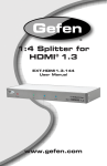
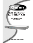
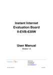
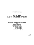
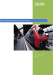
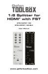
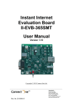
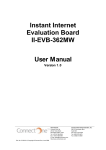
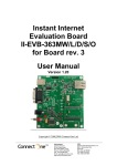
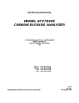
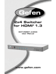
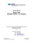
TELEDYNE
INSTRUMENTS
Advanced Pollution Instrumentation
SERVICE NOTE
A Teledyne Technologies Company
6565 Nancy Ridge Dr., San Diego, CA 92121-2251
Phone (858) 657-9800 Fax: (858) 657-9818 Toll Free 1800 324-5190
E-mail: [email protected] http://www.teledyne-api.com/
03-001
27-Feb-2003
CONFIGURATION INSTRUCTIONS FOR ILAN ETHERNET DEVICE
I.
PURPOSE:
To show the low-level software configuration of the iLan Ethernet-to-serial converter used for
Teledyne-API E-series analyzers. The document shows how this device can be configured to the
latest firmware as well as to the correct settings in order to communicate properly with the analyzer’s
serial port. The document contains two main parts, one for the external iLan device as it can be
purchased on the market and as it is used for our A-series analyzers, the other for the internal device,
which is built into the Teledyne-API E-series analyzers.
II.
SYSTEM REQUIREMENTS:
In order to run the configuration utility, you will need any version 32-bit WindowsTM operating system
(Windows 9x, ME, NT, 2000, XP etc) and an internet connection for file download and LAN testing.
One free serial (COM) port on your computer.
III.
NECESSARY PARTS:
For configuration of the external device, you will need one "straight-through" serial cable with DB-9
male connector on the external device side and whatever connector is necessary on the computer
side. A serial cable with DB9 (female and male) connectors is part of the CP27 external iLan kit as
well as a standard RJ-45 Ethernet cable (7 ft, 2 m). A serial cable with DB9 (female and male)
connectors is also included with every E-series analyzer.
For firmware and boot block update of the internal device, you will need a special adapter. Consult the
factory in this case.
IV.
QUICK SUMMARY FOR NETWORK EXPERTS
All iLan devices need to be configured in their configuration mode with
•
•
•
•
(IP)
(GTWY)
(SNET)
(PORT)
A static IP address (default is 000.000.000.000). We do currently not support DHCP.
A network gateway IP address (default is 000.000.000.000).
A subnet mask (default is 255.255.255.0).
A TCP/IP port number (default is 3000).
For Ethernet options built into a T-API analyzer, all of these settings can be changed by following the
procedure described in Section 6.9 of the E-series analyzer user’s manual. To get there quickly press
the following keys on the analyzer front panel: SETUP – MORE – COMM – INET and configure the
individual items shown on the menu and listed above.
Service Note 03-001 Rev A
Page 1 of 6
CSF0001E
3/4/02
To set these parameters for external iLan Ethernet devices and to put the device into SerialNet mode,
follow the procedure described in Section VI of this document.
V.
CONFIGURE AN INTERNAL ETHERNET DEVICE THROUGH THE ANALYZER.
This section describes how to configure your analyzer’s internal ethernet device for a particular network using the analyzer’s front panel. See the instruction manual of your analyzer for more information
and detailed step-by-step instructions.
• Start your analyzer with the Ethernet iLAN. If you are using an external iLan box, the iLAN
device needs to be powered up, connected via serial cable to the analyzer (straight through
cable, make sure both red and green lights are on at the analyzer RS-232 port) and via ethernet
cable to the network.
• Start the analyzer and select SETUP - MORE - COMM. If you see a choice "INET", skip the next
step. If you do not see "INET", continue with the next two steps and continue configuring the
GTWY setting..
• If you do not see INET on the menu, choose COM2, choose EDIT to edit the operation mode of
this particular com port and set QUIET MODE, COMPUTER MODE and ENABLE INET to ON.
When you press ENTR, the mode setting should have a value of “11”. This will enable the
Internet support on COM2.
• Choose NXT and verify that the baud rate of the analyzer is set to 115200 baud for this COM
port. If not, press EDIT and use the NXT and PREV buttons until you see 115200 and press
ENTR, then EXIT.
• For older configurations: If you see two buttons labeled STRT and STOP, press the STOP
button. You may either get a message that the “Stopping Internet – Internet stopped” or you will
get an message “Stopping Internet – Internet Not Stopped”. In either case, and if you do not see
the STRT and STOP buttons, continue with the next step.
• Choose INET-GTWY. Enter the Gateway IP address such as (example only) 172.16.72.2.
Please consult your network administrator for the correct address, do not guess this address and
do not use an address that is already in use on your network. This needs to be a static IP
address, DHCP is not supported. When done, press ENTR.
• Choose IP and enter the IP address of this analyzer such as (example only) 172.16.72.230.
Please consult your network administrator for the correct address, do not guess this address and
do not use an address that is already in use. This needs to be a static IP address. Press ENTR
when done.
• Choose SNET and enter the subnet mask (example: 255.255.252.0) of your network. Please
consult your network administrator for the correct subnet mask. Press ENTR.
• Choose PORT and verify that the port number is set to 3000. Do not change this setting unless
your system administrator asks you to do so.
• If you do not see the buttons STRT and STOP, skip this step, your analyzer will be ready for
Ethernet operation.
On older configurations only: If you see the STRT and STOP buttons, choose STRT to start the
SerialNet mode of the iLAN. You should get a positive response that the network was started
(“Internet Started”) within a few seconds. This should enable you to use the analyzer on the
Service Note 03-001 Rev A
Page 2 of 6
CSF0001E
3/4/02
network. Choose EXIT EXIT-EXIT-EXIT to get back to the main screen. If you get a message
“Internet Not Started”, refer to Section VII of this document for trouble-shooting.
NOTE: On older configurations that show the STRT and STOP buttons on the INET menu: while
the iLan is in SerialNet mode (“Internet Started”), the device cannot change baud rate or any of the
other network settings. If, for any reason, you need to change the system's baud rate or network
settings, you need to STOP the SerialNet mode by choosing SETUP-MORE-COMM-INET-STOP
and wait until you get a positive response that the network was stopped within a few seconds
(“Internet Stopped”). Then change the baud rate or the network settings of your analyzer and start
the network again as described above. You may have to power cycle all devices for the settings to
take effect.
On newer configurations, which do not show the STRT and STOP buttons in the INET menu, this
procedure is done automatically whenever you change a network setting and press ENTR. On
these configurations, the baud rate is fixed to 115200 baud.
NOTE: The above procedure is also applicable for external devices used on A-series analyzers if
the analyzer is equipped with a special software allowing the iLan device to be configured through
the analyzer front panel.
VI.
CONFIGURATION STEPS FOR EXTERNAL ILAN DEVICE
For more information on this external device, manuals and firmware updates, please see the vendor’s
website at http://www.connectone.com/html/ilan.htm
i.
Configuration of iLAN device using the iChipConfig utility.
Follow this procedure only if the iLAN box was not yet configured at the Teledyne-API factory.
• Install the software utility iChipConfig, downloadable at the vendor’s
http://connectone.com/html/utility.asp or from http://www.teledyne-api.com/software/
website
• Connect the iLAN device to the running host computer via serial cable. Power up the iLAN
device. If you are configuring an internal Ethernet adapter, you also need to supply 5V DC
power to the device through the 2-pin connector labeled PL102.
• Start the iChipConfig utility and you should see the
screen shown on the right.
Select from the menu: SerialPorts and select the
port that the iLAN is connected to as well as a baud
rate of 115200. Click OK. You should get a response
“iLan found at COM x at 115200 baud”. Click OK to
dismiss this prompt.
• Select the Full Configuration option. You should get
a tabbed window as shown below. In the tab "LAN
parameters" change settings for the following entries:
•
The MAC address shows a unique serial
number for each iLan device. It cannot be
changed but may be useful to your system administrator.
Service Note 03-001 Rev A
Page 3 of 6
CSF0001E
3/4/02
•
Change the default IP address to an IP address that was assigned to you by your
system administrator, this needs to be a fixed IP address (example only:
172.16.72.230). Do not use or check "Use DHCP" or “Use IP Finder!
•
"Subnet address" (example only: 255.255.252.0)
•
Gateway IP address (example only: 172.16.72.2).
• If you do not know these settings, consult your network administrator and do not try to guess the
correct settings. The iLan will not work unless the IP address, gateway and subnet mask are set
properly.
• On tab "SerialNet parameters", set the "Port settings for SerialNet" to
one-digit number for the baud rate for SerialNet
operation (X=9 = 115200 baud is API default):
• 3 - 2400 baud
•
4 - 4800 baud
•
5 - 9600 baud
•
6 - 19200 baud
•
7 - 38400 baud
•
8 - 57600 baud
•
9 - 115200 baud
X,8,N,1,0, where X is a
• Under the same tab, set the "Server SerialNet port (LPRT)” parameter to 3000. This parameter
needs to match the parameter set in the analyzer firmware. If in doubt, use 3000.
• Click SAVE at the bottom of the window and the program should return to screen one and
confirm successful upload.
ii.
Upgrading the firmware or boot block
If the boot block (iLan BIOS, low level settings) or the firmware need to be upgraded, follow these
steps.
WARNING: When upgrading the boot block, always upload the boot block before uploading the
firmware and do not power cycle the device until both files are uploaded.
• After starting the iChipConfig utility (see above on how to connect your device), choose the
option “iChip Uploader via Serial”. You will see a window as shown below. This window will show
you the COM port and baud rate and that it has detected the device.
• Read the boot block number (0702 in this example) and the software version (IL701B06 with
date in this example). Compare these numbers to the version that you want to upload. The
number 701 in IL701B06 has to be lower than the number of the software you want to upgrade
to and the designator B06 has to be lower than the new version. For example, version 702P19 is
newer than the one shown on right, whereas software 701B05 is older.
Service Note 03-001 Rev A
Page 4 of 6
CSF0001E
3/4/02
• If the boot block needs to be updated, it needs to
be uploaded before any newer software version
is uploaded to the device. If this is the case or if
only the software needs to be updated, click on
the “Firmware” button and search for the new
software on your computer drive. Double-click on
it and click OK to confirm that you want to upload
the new software. A status indicator will show
you the progress and, if upload was successful,
the grayed-out buttons will re-appear as black
and the blue text will show a success message.
• If the boot block was uploaded, you need to
update the device with a new software following
the same steps. WARNING: do not power-cycle
the device until you have followed the boot block
upload with a software upload!!
• Once the boot block and/or software upload was
successful, the device needs to be powercycled.
• After reboot, follow the steps in the previous section to configure or confirm the LAN settings. In
many cases, these settings are retained from previous configuration during the software upload.
REMARK: You can use multiple analyzers on one ethernet port by utilizing T-API's multi-drop option
or a commercially available code activated switch (CAS). CAS units are available for 2, 4, 8, 16 or
more ports and can connect that number of analyzers to one outgoing port (in this case the iLAN
device). A connection string needs to be issued for every analyzer on the chain. The APICOM remote
control program supports both multi-drop and CAS devices.
REMARK: To use APIcom 3.5 or above with the new ethernet connection, configure a new site for
each ConnectOne / embedded ethernet device or CAS / multi-drop chain. Enter the specific IP
address and port number "3000" for each site. Then create the respective instrument names for each
site. Note that multiple analyzers need to have different ID numbers (SETUP-MORE-COMM-ID) on
multi-drop. For code activated switches, a unique port-selection string needs to be programmed for
each instrument. Refer to the manual of the CAS device for this string. T-API sales can help you select
a good CAS.
VII.
TROUBLE-SHOOTING TIPS
The most common problem is that the Ethernet adapter does not start into serial mode when choosing
SETUP-MORE-COMM-INET-START. This applies only to older configurations that show the STRT
and STOP buttons in the INET menu. Here are the most common causes for problems on internal
iLan devices:
• SerialNet mode is already started. Try to stop the SerialNet mode by selecting SETUP-MORECOMM-INET-STOP. If you get an immediate response “Internet Stopped”, the device was
already in SerialNet mode. Start it again.
• Baud rate of SerialNet mode does not match the baud rate of the analyzer. Standard T-API
setting is 115200 baud (115 kbaud), which enables the quickest data transfer possible. A-series
analyzers are limited to 19200 baud and mixed environments of A- and E-series analyzers on a
multi-drop or CAS chain may need to be limited to 19200 baud.
Service Note 03-001 Rev A
Page 5 of 6
CSF0001E
3/4/02
• iLan device is not connected to the correct COM port. The default is COM2 running at 115
kbaud, quiet mode ON, computer mode ON, internet enabled ON (combined mode value of 11)
• Cable connector at the CPU board is reversed (check that pin 1 lines up with pin 1 on the CPU
board).
• Device does not get 5 V DC power or power connector is disconnected. Use a multi-meter to
check the voltage across the power connector PL102, it should be about 5.0 V.
• Network settings are incorrect. Consult your network administrator to double-check these
settings. The IP address of the analyzer needs to match the network and subnet of your network
gateway and/or router server.
• Use the LEDs on the Ethernet device to see if the board responds. If the analyzer is plugged into
a working network, the LNK LED should be on and the ACT LED should be flickering indicating
general network traffic.
Choose SETUP-MORE-COMM-COM2-NXT-(NXT-NXT) until you see the choice TEST. Push
the TEST button and see if the RxD light is flickering. This indicates communications between
the COM port and the device.
Use a computer and try to PING the device (start a DOS command prompt on Windows and type in
PING 172.16.72.230 [press ENTER]
the shown IP address is an example only, use the IP address that you programmed into the device. If
you get a positive response (telling you how long the return took in ms), the device can be seen on the
LAN and your problem may be related to the link between COM port and Ethernet board. If the PING
times out, the device is not accessible through the LAN. In this case, check with your system
administrator to trouble-shoot your LAN.
• Network and/or internal serial-to-ethernet cables are broken.
• Firmware and boot block are not compatible. Consult the factory for firmware updates or check
the ConnectOne website for newer versions (Section 1.)
Service Note 03-001 Rev A
Page 6 of 6
CSF0001E
3/4/02