1
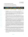
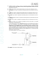
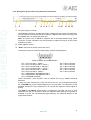
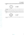
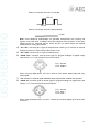
USO RESTRITO
AEQ TH-03
Digital Hybrid of 1 (TH-03.1) or 2 lines (TH-03.2)
with Frequency Extender
USER’S MANUAL
ED. 01/12
V. 1.0 - 31/01/2012
USO RESTRITO
CONTENTS
1. INTRODUCTION....................................................................................................................... 3
1.1. General description............................................................................................................ 3
1.2. General precautions........................................................................................................... 3
1.2.1. Read all instructions................................................................................................ 3
1.2.2. Protection against water and humidity.................................................................... 3
1.2.3. Ventilation, fire and flammable vapors.................................................................... 3
1.2.4. Maintenance............................................................................................................ 3
1.2.5. How to proceed in case of feedback....................................................................... 3
2. PHYSICAL DESCRIPTION OF THE UNIT............................................................................... 4
2.1. Physical description of the 2 lines hybrid: TH-03.2............................................................ 4
2.1.1. Description of the TH-03.2 front panel and controls. .............................................. 4
2.1.2. Description of the TH-03.2 rear panel and connections. ........................................ 6
2.2. Physical description of the 1 line hybrid: TH-03.1.............................................................. 9
2.2.1. Description of the TH-03.1 front panel and controls. .............................................. 9
2.2.2. Description of the TH-03.1 rear panel and connections. ...................................... 10
3. AUDIO CONNECTIONS. ........................................................................................................ 12
3.1. General. ........................................................................................................................... 12
3.1.1. Connection of audio inputs and outputs. .............................................................. 12
4. CONTROL FUNCTIONS......................................................................................................... 12
5. TECHNICAL SPECIFICATIONS.* .......................................................................................... 13
6. A.E.Q. WARRANTY................................................................................................................ 14
2
AEQ TH-03
USO RESTRITO
1. INTRODUCTION.
1.1. General description.
The AEQ TH-03 is a digital hybrid with one or two lines of communication (TH-03.1 and TH-03.2
respectively) that allows to work with analog or digital AES/EBU audio signals (this last option
by means of an additional board). The system allows you to use the frequency extension
function in order to improve the audio quality on the communications through the analogue
telephone line.
In the case of the hybrid with 2 lines (TH-03.2), the user can take advantage of the built-in MixMinus bus. Through this bus is possible to establish a multiplex communication between the
user and the two communication lines connected to the hybrid.
1.2. General precautions.
The following precautions should be observed for safety reasons during all operation and
maintenance of this unit. Failure to comply with all instructions may seriously alter the functions
and performance of the equipment. AEQ will not be responsible for any damage or loss due to
the improper handling of the equipment.
1.2.1. Read all instructions.
Before connecting the equipment to mains and start-up, it is absolutely necessary to read
carefully all the instructions in this manual, in the established order.
If these basic rules are respected, you will obtain the maximum performance of the equipment
from the very start, and, at the same time, you will avoid incorrect or improper operation that
could cause damage to the equipment or personnel.
1.2.2. Protection against water and humidity.
The operation of the equipment in humid environments, near water or wet floors must be
avoided. Nor should it be used in environments where the atmospheric humidity is so high it will
produce regular condensation inside the equipment.
1.2.3. Ventilation, fire and flammable vapors.
The equipment should never be placed near or over a heat source. The use of electrical or
electronic equipment close to fire or flammable vapors is a risk that has to be avoided. All
ventilation grids must be uncovered to allow hot air out and make sure a proper ventilation of
the equipment.
1.2.4. Maintenance.
Any maintenance of this equipment should be carried out by qualified technical service
personnel. AEQ will not be responsible for any damage caused by unauthorized maintenance
operations, nor for any damage caused to other equipment or persons due to such
unauthorized maintenance. Always bear in mind that inside the equipment there is high voltage
and there exists the risk of an electrical shock. The installation of this unit must be carried out by
qualified technical personnel.
1.2.5. How to proceed in case of feedback.
In case you find any feedback reaction in the TH-03 after installation and connection, the
technician should check in the mixing console that there is no signal sent from the TH-03
talkback module to the console module that sends signal to the hybrid.
3
AEQ TH-03
USO RESTRITO
2. PHYSICAL DESCRIPTION OF THE UNIT.
2.1. Physical description of the 2 lines hybrid: TH-03.2.
2.1.1. Description of the TH-03.2 front panel and controls.
1
2
3
4
5
6
7
8
9 10
11
12 13
14
1. “LOC/REM” key of LINE 1: allows you to change between local (without pressing) or
remote control (pressed) of line 1. Both modes are exclusive between them.
When remote control is activated, the control keys “XTND”, “WAIT” and “ON AIR” of
that line are no longer active and their functions are managed through remote control
connector (in order to activate any of these functions, only is required to connect to
ground the corresponding remote signal).
2. “XTND” key of LINE 1: allows you to activate the frequency extension function.
The typical telephone circuits have a limited bandwith between 300 and 4000Hz.
Unfortunately, the most part of the voice energy is contained in frequencies lower than
300Hz, which are lost during transmision through the telephone line. For this reason,
the audio signal has the typical telephone sound, being this loss the most representative
aspect.
The frequency extension function allows to transmit the bandwith between 50 and
300Hz through the telephone line. In order to achieve this, the signal sent undergoes a
250Hz frequency shift, improving the quality of the received signal in its lower
frequencies at the expense of the higher band. The transmitted bandwith is, thus,
between 50 and 3750Hz. The lost 250Hz from the higher frequencies are not very
significant, due to the logarithmic nature of the audio frequency response.
The translation of frequencies takes place by encoding the audio signal before it is sent
to the telephone line. Decoding, i.e., the reverse frequency shift, takes place at the
receiving end, that must be done by the appropriate equipment with the frequency
extension function also activated (another TH-03 hybrid, a TLE-02D communications
unit, a TH-03 EX hybrid, an hybrid module of the COURSE system or a FR33 module of
the FORUM console). The decoded signal has the original bandwith (between 50 and
3750Hz) without having suffered any alteration. Thus, greater depth and clarity is
achieved in the voice signal, even in those communications that take place under the
worst conditions.
3. “WAIT” key of LINE 1: allows you to select WAIT mode (on hold) for the incoming call:
line is connected to the digital hybrid and the signal of the corresponding “PROG. IN”
input is sent to the line. The correspondent hears the program but can not take part in it.
When the key is released, the line returns to the telephone set (if not hung up
previously) or the call is disconected (unless the “ON AIR” key is pressed).
4. “ON AIR” key of LINE 1: allows you to select ON AIR mode for the incoming call: line is
connected to the digital hybrid, the signal of the corresponding “PROG. IN” input is sent
to the line and the signal coming from the line is conducted to the corresponding
“PROG. OUT” connector. The correspondent hears the program and takes part in it.
When "ON AIR" and "WAIT" keys are pressed at the same time, ON AIR mode prevails
over WAIT mode.
4
AEQ TH-03
USO RESTRITO
5. “LEVEL” VUmeters of LINE 1: a pair of 10 segments precision VUmeters that allows
you to monitor the output (“SND” VUmeter) and input signal (“RCV” VUmeter) of the link
established through line 1.
6. “RING” LED of LINE 1: this LED will blink when an incoming call is detected on line 1.
7. “LOC/REM” key of LINE 2: equivalent functionality that the one described for the line 1
key.
8. “XTND” key of LINE 2: equivalent functionality that the one described for the line 1 key.
9. “WAIT” key of LINE 2: equivalent functionality that the one described for the line 1 key.
10. “ON AIR” key of LINE 2: equivalent functionality that the one described for the line 1
key.
11. “LEVEL” VUmeters of LINE 2: equivalent functionality that the one described for the line
1 VUmeters.
12. “RING” LED of LINE 2: equivalent functionality that the one described for the line 1
LED.
13. “MPX” key: allows you to activate the Multiplex function and perform a cross-talk
between lines 1 and 2 and the unit.
In this working mode, the user of AEQ TH-03.2 and two more participants at the ends of
each line can establish a communication in full duplex mode, that is, everyone talks to
everyone and hear each other at all times. When Multiplex function is activated, only the
“PROG. IN” input and “PROG. OUT” output of line 1 are available; the input and output
of line 2 are disabled. Thus, the signal of the line 1 “PROG. IN” input is sent to both
phone lines and the signals coming from both lines are conducted to the line 1 program
output; on the other hand, the signal from the telephone line 1 is also sent to the
telephone line 2 and vice versa.
The operating diagram of this mode is as follows:
14. “POWER” LED: Power On LED indicator.
5
AEQ TH-03
USO RESTRITO
2.1.2. Description of the TH-03.2 rear panel and connections.
1
2
3
4
5 6 7
8
9 10
11 12 13
1. AC power supply connector.
The TH-03 is prepared to operate with supply voltages from 90 to 250 VAC (50/60Hz).
The unit’s mains connector socket has a fuse box, located at the bottom of the plug, and
it’s supplied with a 1A fuse and a spare one.
Note: The power cord of TH-03 is supplied with a European-stardard plug mains
connector. In some countries it may be necessary to replace the plug to fit the current
regulations on them.
2. Power ON/OFF switch.
3. “GPIO” connector for remote control of the unit.
The physical connector used is a DB15 female, with the following pinout:
DB15 connector pinout indentification
- Pin 1: CALL IN LINE 1 - RING 1
- Pin 2: CALL ON WAIT LINE 2 - WAIT 2
- Pin 3: CALL ON AIR LINE 2 - ON AIR 2
- Pin 4: CALL ON WAIT LINE 1 - WAIT 1
- Pin 5: CALL ON AIR LINE 1 - ON AIR 1
- Pin 6: CALL IN LINE 2 - RING 2
- Pin 7: FREQUENCY EXTENSION LINE 1
- Pin 8: FREQUENCY EXTENSION LINE 2
- Pin 9: COMMON GROUND
- Pin 10: Not connected
- Pin 11: Not connected
- Pin 12: Not connected
- Pin 13: Not connected
- Pin 14: Not connected
- Pin 15: Not connected
These connections, when required, must be carried out only by qualified technical
personnel.
In order to control remotely any of the two lines of the unit, you must press previously
the “LOC/REM” key of the corresponding key on the front panel. To activate any of the
available functions the only requirement is to connect the respective remote signal to
ground.
The RING 1 and RING 2 signals allow to recognize the incoming call tone on each
telephone line and can be used to feed two separate LEDs (when the ring signal is
detected on a line, the connected LED lights blinking). The electrical features of this
signal are as follows:
6
AEQ TH-03
USO RESTRITO
-
When the incoming call tone is connected:
100 ms
20 ms
-
When the incoming call tone is disconnected:
0 Volts.
Note: some telephone swithcboards can generate exceptionally low incoming call
signals, much lower than 75 VRMS, which the equipment will not detect. In this case,
please contact our Technical Service, which will give you advice about the required
modification for solving the problem.
4. “TEL. SET” connector (RJ11 type) for line 2 telephone set. Allows you to connect an
external telephone terminal in order to do the dial or take a call.
5. “TEL. LINE” connector (RJ11 type) for telephone line 2.
6. “PROG. OUT” connector (XLR-3p male type) for analogue or digital output (see section
3.1.1) of the line 2 program. This output is disabled when Multiplex function is activated
(see section 2.1.1). The connector pinout is as follows:
Pin 1: Ground
Pin 2: Output +
Pin 3: Output –
When using the digital option, only the L channel of the stereo digital output will carry
audio signal.
7. LED indicator for optional digital AES/EBU input/output board installed and operative for
line 2.
8. “PROG. IN” connector (XLR-3p female type) for analogue or digital input (see section
3.1.1) of the line 2 program. This input is disabled when Multiplex function is activated
(see section 2.1.1). The connector pinout is as follows:
Pin 1: Ground
Pin 2: Input +
Pin 3: Input –
When using the digital option, only the L channel of the stereo digital input will be sent
to the line.
9. “TEL. SET” connector (RJ11 type) for line 1 telephone set. Allows you to connect an
external telephone terminal in order to do the dial or take a call.
10. “TEL. LINE” connector (RJ11 type) for telephone line 1.
7
AEQ TH-03
USO RESTRITO
11. “PROG. OUT” connector (XLR-3p male type) for analogue or digital output (see section
3.1.1) of the line 1 program (or both lines in Multiplex mode). The connector pinout is as
follows:
Pin 1: Ground
Pin 2: Output +
Pin 3: Output –
When using the digital option, only the L channel of the stereo digital output will carry
audio signal.
12. LED indicator for optional digital AES/EBU input/output board installed and operative for
line 1.
13. “PROG. IN” connector (XLR-3p female type) for analogue or digital input (see section
3.1.1) of the line 1 program (or both lines in Multiplex mode). The connector pinout is as
follows:
Pin 1: Ground
Pin 2: Input +
Pin 3: Input –
When using the digital option, only the L channel of the stereo digital input will be sent
to the line.
8
AEQ TH-03
USO RESTRITO
2.2. Physical description of the 1 line hybrid: TH-03.1.
2.2.1. Description of the TH-03.1 front panel and controls.
1
2
3
4
5
6
7
1. “LOC/REM” key: allows you to change between local (without pressing) or remote
control (pressed). Both modes are exclusive between them.
When remote control is activated, the control keys “XTND”, “WAIT” and “ON AIR” are
no longer active and their functions are managed through remote control connector (in
order to activate any of these functions, only is required to connect to ground the
corresponding remote signal).
2. “XTND” key of LINE 1: allows you to activate the frequency extension function.
The typical telephone circuits have a limited bandwith between 300 and 4000Hz.
Unfortunately, the most part of the voice energy is contained in frequencies lower than
300Hz, which are lost during transmision through the telephone line. For this reason,
the audio signal has the typical telephone sound, being this loss the most representative
aspect.
The frequency extension function allows to transmit the bandwith between 50 and
300Hz through the telephone line. In order to achieve this, the signal sent undergoes a
250Hz frequency shift, improving the quality of the received signal in its lower
frequencies at the expense of the higher band. The transmitted bandwith is, thus,
between 50 and 3750Hz. The lost 250Hz from the higher frequencies are not very
significant, due to the logarithmic nature of the audio frequency response.
The translation of frequencies takes place by encoding the audio signal before it is sent
to the telephone line. Decoding, i.e., the reverse frequency shift, takes place at the
receiving end, that must be done by the appropriate equipment with the frequency
extension function also activated (another TH-03 hybrid, a TLE-02D communications
unit, a TH-03 EX hybrid, an hybrid module of the COURSE system or a FR33 module of
the FORUM console). The decoded signal has the original bandwith (between 50 and
3750Hz) without having suffered any alteration. Thus, greater depth and clarity is
achieved in the voice signal, even in those communications that take place under the
worst conditions.
3. “WAIT” key: allows you to select WAIT mode (on hold) for the incoming call: line is
connected to the digital hybrid and the signal of the corresponding “PROG. IN” input is
sent to the line. The correspondent hears the program but can not take part in it. When
the key is released, the line returns to the telephone set (if not hung up previously) or
the call is disconected (unless the “ON AIR” key is pressed)
4. “ON AIR” key: allows you to select ON AIR mode for the incoming call: line is connected
to the digital hybrid, the signal of the corresponding “PROG. IN” input is sent to the line
and the signal coming from the line is conducted to the corresponding “PROG. OUT”
connector. The correspondent hears the program and takes part in it. When "ON AIR"
and "WAIT" keys are pressed at the same time, ON AIR mode prevails over WAIT
mode.
5. “LEVEL” VUmeters: a pair of 10 segments precision VUmeters that allows you to
monitor the output (“SND” VUmeter) and input signal (“RCV” VUmeter) of the
established link.
9
AEQ TH-03
USO RESTRITO
6. “RING” LED: this LED will blink when an incoming call is detected.
7. “POWER” LED: Power On LED indicator.
2.2.2. Description of the TH-03.1 rear panel and connections.
1
2
3
4
5
6 7
8
1. AC power supply connector.
The TH-03 is prepared to operate with supply voltages from 90 to 250 VAC (50/60Hz).
The unit’s mains connector socket has a fuse box, located at the bottom of the plug, and
it’s supplied with a 1A fuse and a spare one.
Note: The power cord of TH-03 is supplied with a European-stardard plug mains
connector. In some countries it may be necessary to replace the plug to fit the current
regulations on them.
2. Power ON/OFF switch.
3. “GPIO” connector for remote control of the unit.
The physical connector used is a DB15 female, with the following pinout:
DB15 connector pinout indentification
- Pin 1: CALL IN LINE - RING
- Pin 2: Not connected
- Pin 3: Not connected
- Pin 4: CALL ON WAIT
- Pin 5: CALL ON AIR
- Pin 6: Not connected
- Pin 7: FREQUENCY EXTENSION
- Pin 8: Not connected
- Pin 9: COMMON GROUND
- Pin 10: Not connected
- Pin 11: Not connected
- Pin 12: Not connected
- Pin 13: Not connected
- Pin 14: Not connected
- Pin 15: Not connected
These connections, when required, must be carried out only by qualified technical
personnel.
In order to control remotely any of the two lines of the unit, you must press previously
the “LOC/REM” key of the corresponding key on the front panel. To activate any of the
available functions the only requirement is to connect the respective remote signal to
ground.
The RING signal allows to recognize the incoming call tone on the telephone line and
can be used to feed a LED (when the ring signal is detected on the line, the connected
LED lights blinking). The electrical features of this signal are as follows:
10
AEQ TH-03
USO RESTRITO
-
When the incoming call tone is connected:
100 ms
20 ms
-
When the incoming call tone is disconnected:
0 Volts.
Note: some telephone swithcboards can generate exceptionally low incoming call
signals, much lower than 75 VRMS, which the equipment will not detect. In this case,
please contact our Technical Service, which will give you advice about the required
modification for solving the problem.
4. “TEL. SET” connector (RJ11 type) for telephone set. Allows you to connect an external
telephone terminal in order to do the dial or take a call.
5. “TEL. LINE” connector (RJ11 type) for telephone line.
6. “PROG. OUT” connector (XLR-3p male type) for program analogue or digital output
(see section 3.1.1). The connector pinout is as follows:
Pin 1: Ground
Pin 2: Output +
Pin 3: Output –
When using the digital option, only the L channel of the stereo digital output will carry
audio signal.
7. LED indicator for optional digital AES/EBU input/output board installed and operative.
8. “PROG. IN” connector (XLR-3p female type) for program analogue or digital input (see
section 3.1.1). The connector pinout is as follows:
Pin 1: Ground
Pin 2: Input +
Pin 3: Input –
When using the digital option, only the L channel of the stereo digital input will be sent
to the line.
11
AEQ TH-03
USO RESTRITO
3. AUDIO CONNECTIONS.
3.1. General.
The audio connections of the TH-03 have been made in accordance to the
recommendations of AES 14-1.992 (ANSIS 4.48-1.992). This recommendation is based upon
the IEC 268-12 of 1.987 (Audio Systems Equipment Part 12, Connector application for Radio
Broadcasting and similar use).
Make sure that the audio cables that you are connecting to the equipment follow this standard.
Otherwise, they have to be replaced or modified, since they can cause problems in the phase of
the audio signal.
3.1.1. Connection of audio inputs and outputs.
The TH-03 can work with analogue or digital AES/EBU signals. These last ones are optionals
and use the same XLR connectors than the analogue ones. Therefore, in the case of the TH03.1 it is possible to use only one of the two types of signal; in the case of the TH-03.2 one line
can be configurated with analog input/output and the other line with digital input/output, or both
of them with only analogue or only digital inputs/outputs.
The TH-03 is provided by default (unless specific request) with analogue inputs and outputs,
allthough these can be converted into digital by means of the insertion of an additional board (or
two, in the case of the TH-03.2) in the main base board and changing some PDP's on that
board. This operation requires opening the unit, so that must be done by specialized personnel
and the equipment must be disconnected from electrical power and telephone line.
In order to find out if the equipment is configured with digital inputs and outputs, it has a LED
indicator (two LEDs in the case of the TH-03.2) on the rear part, between the “PROG.OUT” and
“PROG. IN” connectors (see sections 2.1.2 and 2.2.2).
If you need to convert the TH-03 from analogue to digital, please consult the Technical
Assistance Service of AEQ.
4. CONTROL FUNCTIONS.
The TH-03 has a number of control functions to select the operating mode of each connected
line. All functions are independent for each line.
In local mode, the control functions are activated/desactivated by means of the keys on the
front panel (see sections 2.1.1 and 2.2.1). In remote mode, those functions can be
activated/desactivated by remote control through the corresponding "GPIO" connector (see
sections 2.1.2 and 2.2.2). You can select the operating mode by pressing the "LOC/REM" key
on the front panel. Both modes are exclusive between them.
12
AEQ TH-03
USO RESTRITO
5. TECHNICAL SPECIFICATIONS.*
Audio Inputs and Outputs
Analog program input
Analog program output
Digital program input
(optional by means of additional board)
Digital program output
(optional by means of additional board)
Telephone line interface
Input/output
Bandwith
THD+N Distortion
Absolute noise
Frequency extension
Cross-talk
Supression of electrical echo
Program output level
AC Power Supply
Dimensions
XLR female
Input impedance: >6KΩ
Electronic balancing
Nominal input level: 0dBm
XLR male
Electronic balancing
Nominal output level: 0dBm
XLR female
Nominal input level: -22dBFS
XLR male
Nominal output level: -22dBFS
By transformer
Impedance: 600Ω
With frequency extension desactivated:
300 - 4000Hz, +/-1dB
With frequency extension activated:
50 - 3750Hz, +/-1dB
Line: <0.1%
Program output: <0.1%
Tx: <-80dBm
Rx: <-79dBm
Tx: +250Hz
Rx: -250Hz
In any case, lower than absolute noise
<-75dBm (line impedance 600Ω, signal source at
1KHz, nominal input and output levels)
90 / 250 VAC (50 / 60Hz)
W x D x H (mm): 486 x 238 x 44
* Characteristics are subject to change without prior notice.
13
AEQ TH-03
USO RESTRITO
6. A.E.Q. WARRANTY.
AEQ guarantees that this product has been designed and manufactured under a certified
Quality Assurance System and according to the UNE166002 Standard. AEQ therefore
Guarantees that the necessary test protocols to assure the proper operation and the specified
technical characteristics of the product have been followed and accomplished.
This includes that the general protocols for design and production and the particular ones for
this product are conveniently documented.
1.- The present guarantee does not exclude or limit in any way any legally recognized right of
the client.
2.- The period of guarantee is defined to be twelve natural months starting from the date of
purchase of the product by the first client.
To be able to apply to the established in this guarantee, it is compulsory condition to inform the
authorized distributor or –to its effect- an AEQ Sales office or the Technical Service of AEQ
within thirty days of the appearance of the defect and within the period of guarantee, as well as
to facilitate a copy of the purchase invoice and serial number of the product.
It will be equally necessary the previous and expressed conformity from the AEQ Technical
Service for the shipment to AEQ of products for their repair or substitution in application of the
present guarantee.
In consequence, return of equipment that does not comply with these conditions will not be
accepted.
3.- AEQ will at its own cost repair the faulty product once returned, including the necessary
labour to carry out such repair, whenever the failure is caused by defects of the materials,
design or workmanship. The repair will be carried out in any of the AEQ authorized Technical
Service Center. This guarantee does not include the freight charges of the product to or from
such Authorized Technical Service Center.
4.- No Extension of the Guarantee Period for repaired product shall be applied. Nor shall a
Substituted Products in application of this Guarantee be subject to Guarantee Period Extension.
5.- The present guarantee will not be applicable in the following situations:
improper use or Contrary use of the product as per the User or Instruction Manual; violent
manipulation; exhibition to humidity or extreme thermal or environmental conditions or sudden
changes of such conditions; electrical discharges or lightning; oxidation; modifications or not
authorized connections; repairs or non-authorized disassembly of the product; spill of liquids or
chemical products.
6.- Under no circumstances, whether based upon this Limited Guarantee or otherwise, shall
AEQ, S.A. be liable for incidental, special, or consequential damages derived from the use or
from the impossibility of using the product.
AEQ shall not be liable for loss of information in the disks or data support that have been altered
or found to be inexact, neither for any accidental damage caused by the user or other persons
manipulating the product.
14
AEQ TH-03