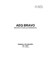
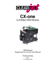
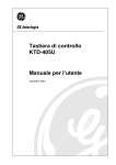
1
AEQ TH-02 EX Mk-III
Digital Hybrid with Frequency Extender
USER’S MANUAL
ED. 10/06
A.E.Q. S.A., manufacturer of this equipment, is a Registered Company in
accordance with UNE EN-ISO-9001standard by Aenor with reg. nr. ER-080/1/96.
The CE equipment marking means that it is in compliance with requirements by the Royal Decree 444/1984
published through the Official State Bulletin of Spain on 1-4-84, transposition of the 89/336/CEE electromagnetic
compatibility directive, and by low voltage directive 73/23/CEE. This appliance is connected to telephone networks
indirectly through interface.
IMPORTANT NOTE
Since end of 2006 there is a new version of the hybrid board of TH-02 EX mkIII unit
(digital hybrid with frequency extender): ED-2 5/06 and ED-3 10/06 editions.
These boards are compatible with previous version of equipment (TH-02 EX mkII) but
there have been changes regarding board power supply.
Therefore, when you connect a new TH-02 EX 2006 hybrid board on a TH-02 EX mkII
unit, it’s essential to remove J1, J2 and J3 jumpers.
When this board is connected on a TH-02 EX mkIII unit, those jumpers must be
mounted.
J2
J3
J1
AEQ TH-02 EX Mk-III
Digital Hybrid with Frequency Extender
1
INDEX
1.2
GENERAL INSTRUCTIONS ................................................................................. 3
General precautions .............................................................................................. 3
1.1.1 Read all instructions.............................................................................. 3
1.1.2 Water and humidity ............................................................................... 3
1.1.3 Ventilation, fire and flammable vapors .................................................. 3
1.1.4 Maintenance.......................................................................................... 3
1.1.5 Warranty................................................................................................ 4
1.1.6 How to proceed in case of feedback ..................................................... 5
General description ............................................................................................... 5
2
2.1
POWER SUPPLY ................................................................................................. 5
General.................................................................................................................. 5
3
3.1
AUDIO CONNECTIONS ....................................................................................... 6
General.................................................................................................................. 6
3.1.1 Connection of audio inputs and outputs ................................................ 6
4
4.1
LINE CONNECTION ............................................................................................. 7
General.................................................................................................................. 7
4.1.1 Connection to two wire lines ................................................................. 7
4.1.2 Connection to four wire lines ................................................................. 7
4.1.3 Connection to two wire microphone lines.............................................. 7
5
5.1
5.2
REMOTE CONTROL ............................................................................................ 8
Remote control connections .................................................................................. 8
Automatic recording option.................................................................................... 8
6
6.1
6.2
CONTROL FUNCTIONS....................................................................................... 9
Control keys .......................................................................................................... 9
Remote mode...................................................................................................... 10
7
7.1
SYSTEM'S CONFIGURATIONS......................................................................... 11
One communication line...................................................................................... 11
7.1.1 Two wire mode. Digital hybrid ............................................................. 11
7.1.2 Four wire mode. Full duplex intercom ................................................. 12
Two communication lines .................................................................................... 13
7.2.1 Multiconference mode......................................................................... 13
7.2.2 Multiplex intercom mode ..................................................................... 14
7.2.3 Dual mode........................................................................................... 14
1
1.1
7.2
8
8.1
8.2
DESCRIPTION OF FRONT AND REAR PANELS ............................................. 15
Front panel .......................................................................................................... 15
Rear panel........................................................................................................... 15
9
TECHNICAL SPECIFICATIONS......................................................................... 16
AEQ TH-02 EX Mk-III
Digital Hybrid with Frequency Extender
2
1
GENERAL INSTRUCTIONS
1.1 General precautions
The following precautions should be observed for safety reasons during all operation
and maintenance of this unit. Failure to comply with all instructions may seriously alter
the functions and performance of the equipment. AEQ will not be responsible for any
damage or loss due to the improper handling of the equipment.
1.1.1 Read all instructions
Before connecting the equipment to mains and start-up, it is absolutely necessary to
read carefully all the instructions in this manual, in the established order. If these basic
rules are respected, you will obtain the maximum performance of the equipment from
the very start, and, at the same time, you will avoid incorrect or improper operation that
could cause damage to the equipment or personnel.
1.1.2 Water and humidity
The operation of the equipment in humid environments, near water or wet floors must
be avoided. Nor should it be used in environments where the atmospheric humidity is
so high it will produce regular condensation inside the equipment.
1.1.3 Ventilation, fire and flammable vapors
The equipment should never be placed near or over a heat source. The use of
electrical or electronic equipment close to fire or flammable vapors is a risk that has to
be avoided.
All ventilation grids must be uncovered to allow hot air out and make sure a proper
ventilation of the equipment.
1.1.4 Maintenance
Any maintenance of this equipment should be carried out by qualified technical service
personnel. AEQ will not be responsible for any damage caused by unauthorized
maintenance operations, nor for any damage caused to other equipment or persons
due to such unauthorized maintenance.
Always bear in mind that inside the equipment there is high voltage and there exists the
risk of an electrical shock. The installation of this unit must be carried out by qualified
technical personnel.
AEQ TH-02 EX Mk-III
Digital Hybrid with Frequency Extender
3
1.1.5
Warranty
AEQ guarantees that this product has been designed and manufactured under a certified
Quality Assurance System and according to the ISO 9001/2002 Standard. AEQ therefore
Guarantees that the necessary test protocols to assure the proper operation and the
specified technical characteristics of the product have been followed and accomplished.
This includes that the general protocols for design and production and the particular ones
for this product are conveniently documented.
1. - The present guarantee does not exclude or limit in any way any legally recognized right
of the client.
2. - The period of guarantee is defined to be twelve natural months starting from the date of
purchase of the product by the first client. To be able to apply to the established in this
guarantee, it is compulsory condition to inform the authorized distributor or –to its effect- an
AEQ Sales office or the Technical Service of AEQ within thirty days of the appearance of
the defect and within the period of guarantee, as well as to facilitate a copy of the purchase
invoice and serial number of the product.
It will be equally necessary the previous and expressed conformity from the AEQ Technical
Service for the shipment to AEQ of products for their repair or substitution in application of
the present guarantee. In consequence, return of equipment that does not comply with
these conditions will not be accepted.
3. -AEQ will at its own cost repair the faulty product once returned, including the necessary
labour to carry out such repair, whenever the failure is caused by defects of the materials,
design or workmanship. The repair will be carried out in any of the AEQ authorized
Technical Service Center. This guarantee does not include the freight charges of the
product to or from such Authorized Technical Service Center.
4. – No Extension of the Guarantee Period for repaired product shall be applied. Nor shall a
Substituted Products in application of this Guarantee be subject to Guarantee Period
Extension.
5. - The present guarantee will not be applicable in the following situations:
Improper use or Contrary use of the product as per the User or Instruction Manual; violent
manipulation; exhibition to humidity or extreme thermal or environmental conditions or
sudden changes of such conditions; electrical discharges or lightning; oxidation;
modifications or not authorized connections; repairs or non-authorized disassembly of the
product; spill of liquids or chemical products.
6. - Under no circumstances, whether based upon this Limited Guarantee or otherwise,
shall AEQ, S.A. be liable for incidental, special, or consequential damages derived from the
use or from the impossibility of using the product.
AEQ shall not be liable for loss of information in the disks or data support that have been
altered or found to be inexact, neither for any accidental damage caused by the user or
other persons manipulating the product.
AEQ TH-02 EX Mk-III
Digital Hybrid with Frequency Extender
4
1.1.6 How to proceed in case of feedback
In case you find any feedback reaction in the TH-02 EX Mk III after installation and
connection, the technician should check in the mixing console that there is no signal
sent from the TH-02 EX Mk IIII talkback module to the console module that sends
signal to the hybrid.
1.2 General description
The TH-02 EX Mk III is a configurable system which can be used in two wire mode as
a digital hybrid, or in four wire mode as a full duplex intercom. In any of these modes
you can take advantage of the frequency extender function.
According to user's requirements, the TH-02 EX Mk III is supplied with one or two lines.
When the system operates with both lines, the user can take advantage of the built-in
Mix-Minus bus. Through this bus it is possible to establish a multiplex and full duplex
communication between the user and the two lines connected to the hybrid. As the
user can select the operating mode of each line, there are different configurations of
the equipment which make the TH-02 EX Mk III a highly versatile equipment, with a
wide range of applications. In Section 7 (System configuration), the user can find
detailed information about any of them.
2
POWER SUPPLY
2.1 General
The description of the front and rear panels of the equipment is described in Section 8.
Extend the sheet with the diagrams to obtain a general view and better comprehension
of all connections.
The TH-02 EX Mk III is prepared to operate with voltages between 90 to 250V AC
without any previous operation. The unit’s mains connector socket has a fuse box with
a 500mA fuse and a spare fuse.
Note: The TH-02 EX Mk III is delivered from factory with a euro-plug mains connector.
In some countries, this connector must be replaced following the local requirements. If
your area does not comply with euro-plug requirements, please, replace the mains
connector before continuing.
AEQ TH-02 EX Mk-III
Digital Hybrid with Frequency Extender
5
3
AUDIO CONNECTIONS
3.1 General
Note: It is recommended to extend the graphical description of audio connections
(Section 8) in order to visualize and improve comprehension of the following
instructions. Bear in mind that if the equipment is supplied with a single line, connectors
for line 2 will not be available.
The connectors of the TH-02 EX Mk III have been made in accordance to the
recommendations of AES 14-1.992 (ANSIS 4.48-1.992). This recommendation is
based upon the IEC 268-12 of 1.987 Audio Systems Equipment Part 12, Connector
application for Radio Broadcasting and similar use.
Make sure that the audio cables that you are connecting to the equipment follow this
standard. Otherwise, they have to be replaced or modified, since they can cause
problems in the phase of the audio signal.
1
Pin connector
( male)
Socket connector
( female)
2
3
Output
Input
PIN ASSIGNMENT
Appliance
1
2
3
Balanced
mono channel
Shield
Positive
polarity
Return
Unbalanced
mono channel
Shield and
return
Positive
polarity
Note 1*
Balanced
mono channel.
Phantom power
Shield and
negative
power
Positive
polarity
and power
Positive
return and
power
Balanced
mono channel.
Power A-B
Shield
Positive
polarity
and power
Negative
return and
power
Note 1*
If a balanced
microphone is
connected
to
an unbalanced
amplifier input,
the pin number
3 of the input
should
be
connected
to
pin number 1.
3.1.1 Connection of audio inputs and outputs
The TH-02 EX Mk III features the following audio connectors:
Program inputs: XLR-3 female connectors for the audio signal inputs to lines (20) and
(26).
Program output: XLR-3 male connector for the signal output from audio lines "ON AIR"
(19) and (25).
When the switcher MPLEX (21) in the back panel is ON, only input (26) and output
(25), will be operative. They respectively carry the mixed signal to and from both lines.
AEQ TH-02 EX Mk-III
Digital Hybrid with Frequency Extender
6
4
LINE CONNECTION
4.1 General
The equipment is in compliance with the 89/336/CEE electromagnetic compatibility
directive, and with the 73/23/CEE low voltage directive.
It is connected to telephone networks indirectly through interface.
Bear in mind that if the equipment is supplied with a single line, connectors for line 2
will not be available.
The TH-02 EX Mk III covers all possible connecting options to standard telephone
circuits and dedicated telephone lines, even to cellular phones. Operation in two or four
wires modes is user selectable with the switches 2W/4W (3) and (8).
4.1.1 Connection to two wire lines
a) Line: RJ-11 telephone connectors (17) and (23), center contacts.
b) Equipment: RJ-11 telephone connectors (16) and (22), center contacts.
4.1.2 Connection to four wire lines
Four wire inputs and outputs: Hartmann pin headers for each line (18) and (24).
From left to right:
pin 1: Output Vpin 2: Output V+
pin 3: Input V+
pin 4: Output V4.1.3 Connection to two wire microphone lines
Sometimes, microphone lines operate in two wire mode. In these cases, the connector
is the same one used for the normal line, this means, connectors (17) and (22).
AEQ TH-02 EX Mk-III
Digital Hybrid with Frequency Extender
7
5
REMOTE CONTROL
5.1 Remote control connections
15 pin Sub-D type connectors (15):
5.2 Automatic recording option
The AEQ TH-02 EX Mk III digital hybrid featuring the "automatic recording option" is
manufactured under client's demand. The lettering "AUTOMATIC RECORDING
OPTION" is printed on the rear panel of the equipment. Line 1 should be used in
remote mode, with the MPLX back switch deactivated.
Pin Nr.
1
2
3
4
5
6
7
8
9
SIGNAL
CALL IN LINE 1
WAITING LINE 2
ON AIR LINE 2
WAITING LINE 1
ON AIR LINE 1
CALL IN LINE 2
ACTIVE EXTENDER LINE 1
ACTIVE EXTENDER LINE 2
COMMON GROUND
Pin Nr.
SIGNAL
10
11
12
13
14
15
NOT CONNECTED (*)
NOT CONNECTED (*)
NOT CONNECTED (*)
NOT CONNECTED (*)
NOT CONNECTED (*)
NOT CONNECTED (*)
(*) Except special versions.
When needed, these connections must be carried out only by qualified technical
personnel
AEQ TH-02 EX Mk-III
Digital Hybrid with Frequency Extender
8
6 CONTROL FUNCTIONS
The TH-02 EX Mk III features control functions for selecting the operation mode of
each connected line. Some of these functions can be executed through a remote
control which uses the signals available in the remote control connector.
All functions are independent for each line. In local mode, control functions are
performed using the keys on the front panel.
6.1 Control keys
Each line of the TH-02 EX Mk III incorporates a group of keys placed in the front panel,
with the following assigned functions:
- EX: When the keys (1) and (6) are activated, the frequency extension function is
activated, displacing all transmission frequencies 250 Hz upwards, and all the
reception frequencies 250 Hz downwards. For a correct operation of the EX function, it
must be carried out in the opposite direction at the other side of the line, by using
another TH-02 EX or an AEQ TLE-02.
- LOC/REM: When it is disconnected, using the keys (2) or (7), the assigned line
operates in local mode, and the remote control of the line does not work.
- 2W/4W: When it is disconnected, using the keys (3) or (8), the assigned line operates
in two wire mode, this means, as a digital hybrid connected to the normal line.
- T / W: In two wire mode, when pushing the keys (4) or (9), the incoming signal
remains in stand by (WAIT). The caller hears the program, but can not take part. When
the key is released, the line returns to the telephone set or on air, if the ON AIR
switcher is activated. In four wire mode, the four wire input signal is in telephone mode.
Likewise, the line is in two wire mode.
- ON AIR: In two wire mode, when the keys (5) and (10) are activated, the line is
connected to the digital hybrid, and the incoming signal is ON AIR, this means, goes
out through the respective PROG-OUT connector.
In four wire mode, the incoming signal is ON AIR, and so it is available in the
respective PROG-OUT connector.
AEQ TH-02 EX Mk-III
Digital Hybrid with Frequency Extender
9
6.2 Remote mode
When the LOC/REM key of a line (2) or (7) is activated, the function of the control keys
EX, T/W and AIR of that line become available in the remote connector. To activate
one of those functions from a remote control the only requirement is to connect the
respective remote signal to ground.
Additionally, there are two signals in the remote connector, RING 1 and RING 2, for
recognizing the incoming call tone for each telephone line. These signals have the
following electric characteristics:
When the incoming call tone is connected:
CALL IN SIGNAL:
100 ms
20 ms
When it is disconnected:
CALL IN SIGNAL:
0 Volts.
These signals can be used to feed a LED. When an incoming signal is detected in the
line, the LED connected will blink.
Note: Some telephone switchboards can generate exceptionally low incoming call
signals, much lower than 75 VRMS, which the equipment will not detect. In this case,
consult our Technical Service, which will give you advice about the required
modifications for solving the problem.
AEQ TH-02 EX Mk-III
Digital Hybrid with Frequency Extender
10
7
SYSTEM'S CONFIGURATIONS
7.1 One communication line
If the AEQ TH-02 EX Mk III has only one line connected, the user can use it in two wire
mode, as a digital hybrid, or in four wire mode, as a full duplex intercom.
7.1.1 Two wire mode. Digital hybrid
Operative principles: Circuits called "telephone hybrids" where defined by the
telephone companies in order to separate the sent and received signals of a standard
two wire telephone pair. The isolation between both signals is evaluated using the
parameter "hybrid rejection" or "transhybrid loss", regarding the amount of electrical
echo that can be rejected by the hybrid. The higher the rejection is, the lower will be the
signal sent to the reception circuit.
The electrical echo, besides of being a source of distortion, can cause echo on a
communication when it is carried out through a long distance link. These problems get
even worse when you want to implement a teleconference terminal or to join several
speakers in a telephone conference.
Analog hybrids: The analog hybrid’s operation is based in obtaining the greatest
adaptation possible between its balance impedance and that of the telephone line at
every moment. The only way of obtaining it is measuring the loop of the telephone and
connecting a balanced impedance according to the measure.
This system has two great drawbacks:
a) It does not consider the variations generated by the distant telephone loop, nor the
variations due to changes of temperature, humidity, etc.
b) If the system is transferred it will be needed to measure impedance and to balance it
again.
Digital hybrid: This model is based on an electrical echo cancellation system,
generated by a conventional analog hybrid, through digital signal processing.
Using an adaptative digital filter, it is possible to analyze the features of the telephone
line and adapt the system to them as much as possible. The response of the filter is
automatically set up to synthesize a signal, and obtain one similar to the electrical
echo, and then subtract it for eliminating the real signal.
The advantage of this process is that it is fully automatic and so, it does not require any
measurement or pre-adjustment of the system depending on the connected wire pairs.
Using high resolution digital signal processors, it is also possible to reach levels of
acoustical echo cancellation high enough to guarantee a real multiconference system.
AEQ TH-02 EX Mk-III
Digital Hybrid with Frequency Extender
11
AEQ TH-02 EX Mk III digital hybrid: The lay-out of the equipment operating in two
wire mode is the following:
ENTRADA AL PROGRAMA
PROGRAM INPUT
A/D
D/A
ECO ELÉCTRICO
ELECTRICAL ECHO
AFIR
SALIDA DEL PROGRAMA
PROGRAM OUTPUT
AIR
-
D/A
WAIT
LÍNEA TELEFÓNICA
TELEPHONE LINE
+
A/D
The telephone line is connected to the digital hybrid when you select T / W or AIR on
the keyboard.
When the function T / W is activated, and the function AIR not, the person calling can
listen to the program, but can not take part (there is not output signal). If AIR is
selected, he can listen and also take part in the program (there is output signal).
7.1.2 Four wire mode. Full duplex intercom
When the 2W/4W function is activated, the AEQ TH-02 EX Mk III operates in four wire
mode, it means, as a full duplex intercom. This operation mode is based on the same
principles explained in the precedent chapter. In this case, the AEQ TH-02 EX Mk III
cancels the acoustical echo in the remote terminal, generated by feed-back between
the microphone and the speaker when they are both on.
For better understanding of the four wire operation mode, let's think of a typical
application. The user adjusts the gain of the speaker, in such way that the level of the
speaker on the remote terminal is the same as the level of the near speaker when he
listens to himself. As a result, the gain in the system is almost 0 dB. This, of course,
generates oscillation if the acoustic echo is significant. Depending on the features of
the acoustic medium, the acoustic echo and its effects will be different and the
cancellation degree must be introduced in the path of the echo. Ideally, the cancellation
of the acoustic echo requires a delay of the same duration than the response time of
the echo.
The AEQ TH-02 EX Mk III, operating in four wire mode, cancels the near acoustic
echo. The 256 steps adaptative filter cancels the echo with a delay equal or lower than
this response. It means that there are operative limits when the AEQ TH-02 EX Mk III
operates in four wire mode. Controlling the speaker's gain properly and using
directional microphones, it is possible to operate with a speaker without problem.
AEQ TH-02 EX Mk-III
Digital Hybrid with Frequency Extender
12
The diagram of the AEQ TH-02 EX Mk III operating in four wire mode is the following:
SALIDA 4 HILOS
4 WIRE OUTPUT
ENTRADA AL PROGRAMA
PROGRAM INPUT
A/D
D/A
AFIR
ECO ACÚSTICO
ACOUSTIC ECHO
24 Bits
SALIDA DEL PROGRAMA
PROGRAM OUTPUT
AIR
-
D/A
WAIT
+
A/D
ENTRADA 4 HILOS
4 WIRE INPUT
7.2 Two communication lines
When the AEQ TH-02 EX Mk III features two communication lines and the switcher
MPLX at the back panel is activated, the user can benefit from the built-in Mix-Minus
bus. The possible configurations of the equipment when it operates in this mode are
the following:
7.2.1 Multiconference mode
When both lines operate in two wire mode, the AEQ TH-02 EX operates in
multiconference mode. In this case, the user of the AEQ TH-02 EX and two more
participants at the ends of both lines can maintain a conversation in full duplex mode, it
means, everybody talks with each other and listens to each other simultaneously in
every moment.
The diagram for this mode is the following:
ENTRADA AL PROGRAMA
PROGRAM INPUT
LÍNEA TELEFÓNICA 1
TELEPHONE LINE 1
LÍNEA TELEFÓNICA 2
TELEPHONE LINE 2
SALIDA DEL PROGRAMA
PROGRAM OUTPUT
AEQ TH-02 EX Mk-III
Digital Hybrid with Frequency Extender
13
7.2.2 Multiplex intercom mode
If both lines operate in four wire mode, it is possible to establish a full duplex
communication between two intercoms and the AEQ TH-02EX Mk III, in the same way
a multiconference is set up when both lines are operating in two wire mode .
ENTRADA AL PROGRAMA
PROGRAM INPUT
SALIDA 4 HILOS LÍNEA 1
4 WIRE OUTPUT LINE 1
ECO ACÚSTICO 1
ACOUSTIC ECHO 1
ENTRADA 4 HILOS LÍNEA 1
4 WIRE INPUT LINE 1
SALIDA 4 HILOS LÍNEA 2
4 WIRE OUTPUT LINE 2
ECO ACÚSTICO 2
ACOUSTIC ECHO 2
SALIDA DEL PROGRAMA
PROGRAM OUTPUT
ENTRADA 4 HILOS LÍNEA 2
4 WIRE INPUT LINE 2
Both intercoms are interconnected through the Mix-Minus bus, and the user of the AEQ
TH-02EX Mk III can also maintain communication with them. The equipment cancels
the acoustic echo generated in each terminal connected to the equipment.
7.2.3 Dual mode
In this operation mode, a line operates as a digital hybrid and the other as a full duplex
intercom. In this way, the user of the AEQ TH-02 EX Mk III is connected with an
intercom on one line and a caller on the other, connecting both of them with each other.
ENTRADA AL PROGRAMA
PROGRAM INPUT
SALIDA 4 HILOS LÍNEA 1
4 WIRE OUTPUT LINE 1
ECO ACÚSTICO
ACOUSTIC ECHO
ENTRADA 4 HILOS LÍNEA 1
4 WIRE INPUT LINE 1
LÍNEA TELEFÓNICA 2
TELEPHONE LINE 2
SALIDA DEL PROGRAMA
PROGRAM OUTPUT
AEQ TH-02 EX Mk-III
Digital Hybrid with Frequency Extender
14
8
8.1
DESCRIPTION OF FRONT AND REAR PANELS
Front panel
1) Line 1 frequency extensor function key.
2) Line 1 local / remote mode selector key.
3) Line 1 2W / 4W mode selector key.
4) Line 1 hook on / hook off key.
5) Line 1 key for connection of audio signal to program output.
6) Line 2 frequency extensor function key.
7) Line 2 local / remote mode selector key.
8) Line 2 2W / 4W mode selector key.
9) Line 2 hook on / hook off key.
10) Line 2 key for connection of audio signal to program output.
11) Power On LED indicator.
12) On / Off switch.
8.2
Rear panel
13) Mains connector.
14) Remote control connector.
15) RJ-11 connector for Line 2 telephone set.
16) RJ-11 connector for Line 2.
17) Four wire input / output connector for Line 2.
18) XLR male connector for Line 2 program output.
19) XLR female connector for Line 2 program input.
20) Key for Multiplex or independent operation.
21) RJ-11 connector for Line 1 telephone set.
22) RJ-11 connector for Line 1.
23) Four wire input / output connector for Line 1.
24) XLR male connector for program output to Line 1 (or both lines in Multiplex
operation mode).
25) XLR female connector for input program from Line 1 (or both in Multiplex operation
mode).
AEQ TH-02 EX Mk-III
Digital Hybrid with Frequency Extender
15
9
TECHNICAL SPECIFICATIONS
AUDIO INPUTS
Program input:
Input impedance:
Nominal input level:
Four wire input:
Input impedance:
Nominal input level:
Transformer balanced.
> 6 KOhms.
0 dBm.
Transformer balanced.
> 1 KOhms.
0 dBm.
AUDIO OUTPUTS
Program output:
Nominal output level:
Four wire output:
Nominal output level:
Transformer balanced.
0 dBm.
Transformer balanced.
0 dBm.
TELEPHONE LINE INTERFACE
Input / Output:
Transformer balanced.
Impedance:
600 Ohms.
Nominal input level:
- 10 dBm.
Nominal output level:
- 6.5 dBm.
*In multiconference mode, the output level of the telephone line provinient from the
other line (nominal input level) is - 7.5 dBm.
TWO WIRE MODE
Bandwidth (extender not active):
Bandwidth (extender active):
Line: 300 - 4.000 Hz +/- 1 dB.
Line: 50 - 3.750 Hz +/- 1 dB.
Program output: 300 - 4.000 Hz +/- 1 dB.
Program output: 50 - 3.750 Hz +/- 1 dB.
Distortion + THDN:
1 KHz with nominal input and output levels:
Line:
< 0.20 %.
Program output:
< 0.15 %.
Absolute noise:
TX =< - 66 dBm.
RX =< - 68 dBm.
Frequency extensor:
TX = 250 Hz.
Rx = - 250 Hz.
Cross-talk in any case: Lower than absolute noise.
SUPPRESSION OF ELECTRICAL ECHO
- One line connected:
Line impedance:
600 Ohm.
Signal source:
1 KHz.
Nominal input and output levels.
Program output level:
< - 64 dBm typical.
- Two lines connected:
Line impedance:
600 Ohm.
Signal source:
1 KHz.
Nominal input and output levels.
Program output level:
< - 58 dBm typical.
AEQ TH-02 EX Mk-III
Digital Hybrid with Frequency Extender
16
FOUR WIRE MODE
Bandwidth (extender not active):
Bandwidth (active extender):
Line: 300 - 4.000 Hz +/- 1 dB.
Line: 50 - 3.750 Hz +/- 1 dB.
Program output: 300 - 4.000 Hz +/- 1 dB.
Program output: 50 - 3.750 Hz +/- 1 dB.
Distortion + THDN:
1 KHz with nominal input and output levels.
Four wire output:
< 0.10 %.
Program output:
< 0.10 %.
Absolute noise:
TX =< - 66 dBm.
RX =< - 68 dBm.
Frequency extender:
TX = 250 Hz.
Rx = - 250 Hz.
Cross-talk in any case: Lower than absolute noise.
AC POWER SUPPLY:
90 / 250 V 50 - 60 Hz
DIMENSIONS:
19 " rack (1 unit height).
Width: 482 mm. (19 ").
Height: 44.5 mm. (1.75 ").
Depth: 356 mm. (14 ").
AEQ TH-02 EX Mk-III
Digital Hybrid with Frequency Extender
17