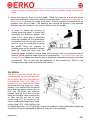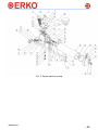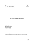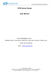
1
ISO 9001 ISO 14001 USER’S MANUAL □ GC_50-H700-E □ GC_100-H700-E SAFETY CABLE CUTTING SET TYPE GC_50-H700-E AND GC_100-H700-E #VGCE20111108 Producent / Producer / Производитель Zakłady Metalowe ERKO R. Pętlak spółka jawna Bracia Pętlak ul. Ks. Jana Hanowskiego 7, 11-042 JONKOWO k/OLSZTYNA tel./fax (+48) 089 5129273 NIP: 739-020-46-93 e-mail: [email protected], [email protected] serwis informacyjny: www.erko.pl. Thank you for buying our product Before using this equipment, please carefully read the user’s manual and maintenance recommendations. CONTENTS 1. 2. 3. 4. 5. 6. 7. 8. 9. SPECIFICATION .............................................................................................. 2 APPLICATION ............................................. Błąd! Nie zdefiniowano zakładki. CONSTRUCTION ........................................ Błąd! Nie zdefiniowano zakładki. PRINCIPLES OF OPERATION ................... Błąd! Nie zdefiniowano zakładki. SPARE PARTS ............................................ Błąd! Nie zdefiniowano zakładki. MAINTENANCE RECOMMENDATION ....... Błąd! Nie zdefiniowano zakładki. REMARKS ................................................... Błąd! Nie zdefiniowano zakładki. RECYCLING ................................................ Błąd! Nie zdefiniowano zakładki. SERVICE ........................................................................................................ 11 * ERKO sp. j. has the right to modify the product as a result of a modernization. ISO 9001 ISO 14001 -1- #VGCE20111109 Prior to start working read the user’s manual and health and safety recommendations 1. SPECIFICATION MODEL GC_50-H700-E Max. nominal voltage GC_100-H700-E 60kV Max. diameter for Al and Cu wires 50mm 96mm Max. diameter for Al and Cu wires reinforced with steel wire or stranded wire 30mm ----------------- 9,5kg / 3,6kg 9,5kg / 7,0kg Weight pump / hydraulic head Max. lever torque 110 Nm Working medium Hydraulic oil L-HM 22 Oil tank volume Fast hydraulic circuit pressure Fast hydraulic circuit output Max. working pressure Working pressure output Temperature of work Hydraulic hose Drive 0,5 dm 3 20 bar 3 5,5 cm / cycle 630 bar 3 0,9 cm / cycle -20÷50 °C High pressure Carrying no electric charge 10m (Standard length) foot-operated 2. APPLICATION Type GC_50-H700-E and GC_100-H700-E safety cable cutting sets are portable footoperated tools designed to cut copper and aluminum wires also reinforced with steel wire or stranded wire in which it is not possible to determine unequivocally state without tension. GC_50-H700-E - Designed to cut wires with a diameter up to 50mm. In the case of reinforced wires (including the AFL) or with a steel band maximum diameter must not exceed 30mm. GC_100-H700-E - Designed to cut wires with a diameter up to 96mm. Should not be used for cutting reinforced wires (including the AFL). #VGCE090128 -2- 3. CONSTRUCTION Sets for safe cutting type GC_50-H700-E and GC_100-H700-E consist of double-circuit pump H700 Hydraulic cutting heads type: GC_50 or GC_100. The pump head is connected with hydraulic hose carrying no electric charge. The entire system is filled with oil of electrical breakdown reduced resistance. The cutting head is equipped with earthing wire. . abcd- piston actuator draining valve oil tank Rys. 1. Hydraulic diagram. 4. PRINCIPLES OF OPERATION Hydraulic system Description of the hydraulic system: a- głowica tnąca b- przyłącze uziemiające c- pompa zasilająca 1. Prepare the earthing connection of the hydraulic head, for example by connecting the grounding wire to a stationary earthing element or grounding to the earth. Make sure that the potential of the earthing connection is close to the earth potential. Grounding element should be made in accordance with regulations in force to ensure safe operation. Install the head to cut the cord. The head has to be mounted using suitable protective gloves for live-wire working. Working without proper gloves can cause electric shock and death. If the bare overhead conductors are cut, unconditionally and beforehand such conductors must be ground in -3- #VGCE20111109 order to protect working person from electric shock possible during installing the head. 2. Uncoil the hydraulic hose to its full length. Place the pump on a level and paved ground protecting the pump from falling during operation. loosen the oil filler cap by about one turn (in order to unseal of oil tank). Theuser should be located as far as possible from the cut cable. The earthing wire should be placed in the opposite direction than the hydraulic hoes (uncoil wires to their full length). 3. In order to initiate the process of cutting press the pedal in cycles [26] observing the pressure gauge. The cable is cut, when after a significant pressure increase on the manometer a pressure drop occurs and it will not grow in spite of continuing to pump the pedal. Once the process is finished press on the pressure release lever [4]. Press the lever until the pressure gauge indicates 0 value, then hold the lever still for several seconds in order to let the hydraulic head return to its initial position. Turn the oil filler cap tight having finished. Make sure that the cap is tightened, otherwise a storage in a humid environment the oil may lose the parameter of non conductivity. Check if the cutting process has been successful with caution. OIL REFILL The tank should be refilled with oil recommended by the manufacturer. An oil other than the manufacturer recommends may not fulfill the condition of non conductivity. Place the pump and the head on a level surface. The head should be placed 9 lower than the pump. Loosen the oil filler cap [9], press the pressure 4 release lever [4] to let the oil move back into the tank, then unscrew the oil filler cap [9] and the oil level 31 control plug [31], top up the oil (till the oil overflows through the oil level control plug [31]). After refilling the oil tighten the plugs ( no. [31] and [4]). Check the condition of the seals before tightening the plugs (if they are damaged or worn out, they has to be replaced). #VGCE090128 -4- DEAERATION To aerate the pump: Place the pump on a level surface. The head should be placed lower than the pump. Loosen the oil filler cap[9]. Press several times the pump pedal then press the pressure release lever[4]. Wait a minute. Repeat the action 4-5 times. Check the oil level, refill if necessary (see the oil refill). 5. SPARE PARTS Under no circumstances do not disconnect the hydraulic hose or the earthing wire. Use only original spare parts and oils for repairs and maintenance. To ensure safe operation, we suggest to leave any repairs to the manufacturer. No. Quantity 1 2 3 1 1 1 4 1 -5- Name Hydraulic cutting head GC50 / GC100 Hydraulic pump Earthing wire 10m. Carryinh no electric charge high pressure hydraulic hose Code EPCU_HOOS-D-25-1,5 HPWC_090-100-70 #VGCE20111109 Pic. 2. Spare parts for pump. #VGCE090128 -6- No. 1 2 3 4 5 6 7 8 9 10 11 12 13 14 15 16 17 18 19 20 21 22 23 24 25 26 27 28 29 30 31 32 33 34 35 36 37 38 39 40 41 42 43 44 45 46 47 48 49 50 51 -7- Ilość 1 1 1 1 1 1 1 1 1 1 1 1 1 1 1 1 1 1 1 1 1 1 1 1 2 1 1 1 Name of element Main body Block Piston Pressure release lever Spring Bolt Bolt Pin’s nut Deaerator Washer Valve’s slide Tank Valve’s screw Valve’s screw Valve’s clamp Valve’s clamp Washer Reduction Valve’s axis Pin Protection cap Valve’s shield Spring Spring Spring Pedal assembly Basis Spring Ordering code H700-01-01 H700-01-02-B H700-01-03-A H700-01-04-C H700-01-05-B H700-01-06-A H700-01-07-A H700-01-08 H700-01-09-A H700-01-10 H700-01-12-C H700-01-13 H700-01-14-A H700-01-15-A H700-01-16-A H700-01-17-A H700-01-18-B H700-01-19-A H700-01-20 H700-01-21-A H700-01-22-A H700-01-23 H700-01-24-A H700-01-25 H700-01-26-A H700-02-00-A H700-03-00-A WH10-01-22-A 1 4 2 1 3 3 2 2 2 2 1 1 Valve’s clamp Ring Tap screw Screw Screw Washer Ball Ball Ball O-ring O-ring O-ring HR300-17-A NEZO_PZ-8 NEZS_WP-M4-6-OC NEZS_WI-M6-10-8.8OC NEZS_WI-M6-20-8.8OC NEZP_P1A-6.4-OC NLKU_6,35 NLKU_4,75 NLKU_8 HUOR_OR57-3 HUOR_OR8,3-2,4 HUOR_OR3,3-2,4 1 1 1 1 2 2 1 1 1 Manometer Sealing ring Sealing ring Wiper ring Ball Cap Washer Filter Rubber casing HMAN_63-1000-G1/4-T HUTR_RR1300250-Z52N HUTR_RS1500100-T46N HPZG_WSA-000250-N9MMN HUTR_DB0000635-N7696 HOKO_S-VSTI-M10-1-ED HOPO_KDS12A3C HFIL_H-700-FSO NANP_TYP-126-P #VGCE20111109 #VGCE090128 -8- Spare parts for GC50/H700/E No. Quantity 52 53 54 55 56 57 58 59 60 61 62 63 64 65 66 67 68 69 70 71 72 73 74 1 1 1 2 1 1 1 1 1 1 1 1 1 2 2 2 2 4 1 1 1 1 1 Name of element Cylinder Follower Bushing Joint Movable knife Fixed knife Spring Bolt Pin Guide bar Guide bar Piston Sealing ring Ring Nut Screw Screw Pin Spring pin Ring Ring Hydraulic port Chain Ordering code GC50-01 GC50-02 GC50-03 GC50-04 GC50-05 GC50-06 GC50-07 GC50-08 GC50-09 GC50-10 GC50-11 HR100-02-A HUPU_U1-25-7,5 NEZO_PZ-10 NEZN_HNB-M8-OC NEZS_WI-M6-20-8.8OC NEZS_WI-M8-40-8.8OC NEZK_WH-6M6-28 NEZK_S2-3-20 NAKO_KOL-25 NAKO_KOL-16 HOPP_S10-M12-70 NALG_LAN-2M Spare parts for GC100/H700/E No. Quantity 52 53 54 55 56 57 58 59 60 61 62 63 64 65 66 67 68 69 70 71 72 73 74 75 76 77 78 79 1 1 1 1 1 1 1 2 2 1 1 1 1 1 1 1 2 1 1 1 2 2 2 4 1 2 1 1 -9- Name of element Left joint Left guide bar Stud complete Right joint Right bar Fixed knife Distancing elements Screw Screw Joint’s sleeve Follower Movable knife Cylinder Spring Piston Sealing ring Ring Handle complete Grip Pin Screw Nut Pin Pin Pin Ring Chain Hydraulic port Ordering code GC100-06-L GC100-08 GC100-05 GC100-06-P GC100-07 GC100-01 GC100-12 NEZS_WKI-M8-16-10.9OC NEZS_WI-M8-30-8.8OC GC100-04 GC100-10-A GC100-02 GC100-03 GC100-14-A HR100-02-A HUPU_U1-25-7,5 NEZO_PZ-10 GC100-11 NAHK_TYP-738 NEZK_S2-4-18 GC100-13 NEZN_HNB-M10-OC NEZK_WH-6M6-35 NEZK_WH-8M6-30 GC50-09 NAKO_KOL-25 NALG_LAN-2M HOPP_S10-M12-70 #VGCE20111109 6. MAINTENANCE RECOMMENDATION 1. Work may be carried out by an adult person, sober, having adequate training 2. Before starting work, check the technical condition of the set. 3. Maximum working pressure was set by the manufacturer at the overflow valve on the value of 630 bar and can’t be adjusted during operation of the tool. 4. In case of oil loss, the oil should be refilled and the pump deaerated if necessary. USE ONLY OIL RECOMMENDED BY THE MANUFACTURER. OIL OF A DIFFERENT TYPE MAY NOT FULFILL THE CONDITION OF ELECTRIC CHARGE NON CONDUCTIVITY. 5. The oil should be CHANGED every 12 months. Use oils in accordance with DIN 51524 Part 3, Class HVLP or ISO 6743/4 Class HV, with a viscosity of ISO VG 32. Use oil Hydrol ® L-HV 32). 6. The oil used in the hydraulic system must meet the minimum requirement of 60 kV during the certification test with the device. Electrical properties of oil may change over time therefore regular changing of the oil is very important. 7. It is recommended to inspect the cleanliness of the hydraulic system, rinsing, changing oil, pressure adjustment every 12 months. Performing these service by the manufacturer gives guarantee that oil used for change was appropriate and free of moisture (that could affect the fulfillment of requirements described by standards) 8. The conservation of oil purity and the periodic oil change is essential for the sustainability of hydraulic components and extends much of their durability and reliability. Oil Purity: Grade 9 (recommended 8) according to NAS 1638. 9. Protect the device from influence of weather factors, corrosion, contamination and mechanical damage. If the tool became accidentally wet, it has to be dried. If the hydraulic system becomes affected by moisture, it has to be rinsed. These actions should be performed by manufacturer in order to be performed correctly. If the tool will not be used for a longer time it has to be preserved and keep in a dry place (the deaeration cap should be closed) 10. Do not leave the hydraulic system under pressure (always release pressure after work) 11. Use appropriate required working cloths 7. REMARKS 8. RECYCLING Once the products cycle comes to an end, all the elements of the tool must be recycled according to existing law. 9. SERVICE Erko insures warranty and after warranty service. #VGCE090128 - 10 -