1
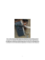
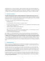
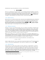
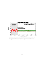
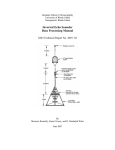
Figure 2. Schematic diagram of the tidal turbulence mooring (TTM).
In order to produce high-fidelity spectra and spatial coherence estimates from moored ADV measurements, motionsensor measurements must be tightly synchronized with ADV velocity measurements. Currently Nortek’s VectorTM is
the only instrument that can be purchased ‘off the shelf’ with a tightly synchronized inertial motion sensor (IMU).
These instruments were used for the TTM test deployments.
2.2.1
Record position and orientation of the ADV head
For deployments involving cable-head IMU-ADVs, it is critical to record the position and orientation of the ADV
head relative to the ADV body (pressure case). Details of the definitions of these coordinate systems can be found
in appendix A. The variables should be measured as accurately as possible, as errors will propagate through motioncorrection calculations and lead to errors in the motion-corrected velocity measurements. As a rule of thumb: the
*
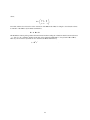
vector ~lhead
should be measured to within a few mm. The orientation matrix of the ADV-head, H, should be measured to within ≈ 2%, (≈ 2 Euler-angle degrees).
2.2.2
Software configuration
At least as important as recording the orientation of the ADV head relative to the ADV body is configuring the ADV
to record the correct data channels for performing motion correction. Three primary data channels are needed to
perform motion correction.
1. The linear acceleration vector, ~a, is integrated to obtain an estimate of the translational-velocity of the ADV
body and head.
~ , is used to estimate the velocity of the head that is due to rotation of the
2. The angular rotation rate vector, ω
ADV about the IMU.
4