1
S m a r t L E W I S TM T R X
TDA5340
High Sensitivity Multi-Channel Transceiver
User Manual
Revision 1.0, 17.02.2012
Wireless Sense & Control
Edition 17.02.2012
Published by
Infineon Technologies AG
81726 Munich, Germany
© 2012 Infineon Technologies AG
All Rights Reserved.
Legal Disclaimer
The information given in this document shall in no event be regarded as a guarantee of conditions or
characteristics. With respect to any examples or hints given herein, any typical values stated herein and/or any
information regarding the application of the device, Infineon Technologies hereby disclaims any and all warranties
and liabilities of any kind, including without limitation, warranties of non-infringement of intellectual property rights
of any third party.
Information
For further information on technology, delivery terms and conditions and prices, please contact the nearest
Infineon Technologies Office (www.infineon.com).
Warnings
Due to technical requirements, components may contain dangerous substances. For information on the types in
question, please contact the nearest Infineon Technologies Office.
Infineon Technologies components may be used in life-support devices or systems only with the express written
approval of Infineon Technologies, if a failure of such components can reasonably be expected to cause the failure
of that life-support device or system or to affect the safety or effectiveness of that device or system. Life support
devices or systems are intended to be implanted in the human body or to support and/or maintain and sustain
and/or protect human life. If they fail, it is reasonable to assume that the health of the user or other persons may
be endangered.
TDA5340
SmartLEWISTM TRX
Revision History
Page or Item
Subjects (major changes since previous revision)
Revision 1.0, 17.02.2012
Chapter 1.1
Frequency extension of 434MHz Band
Figure 1
Figure changed
Figure 2
Figure changed
Chapter 6.9
Block Diagram changed + RF frequency calculation for TX
Chapter 6.12.1
ASK sloping calculation of register values changed
Chapter 6.12.2
GFSK calculation for NRZ inserted
Signal Detector Range
Selection Register
Reset value changed
FSK Noise Detector
Configuration Register
Reset value changed
TX RF Configuration Register
Reset value changed
Antenna Switch Configuration
Register
Reset value changed
RF Control Register
Reset value changed
RX Control Register
Reset value changed
Trademarks of Infineon Technologies AG
AURIX™, C166™, CanPAK™, CIPOS™, CIPURSE™, EconoPACK™, CoolMOS™, CoolSET™,
CORECONTROL™, CROSSAVE™, DAVE™, EasyPIM™, EconoBRIDGE™, EconoDUAL™, EconoPIM™,
EiceDRIVER™, eupec™, FCOS™, HITFET™, HybridPACK™, I²RF™, ISOFACE™, IsoPACK™, MIPAQ™,
ModSTACK™, my-d™, NovalithIC™, OptiMOS™, ORIGA™, PRIMARION™, PrimePACK™, PrimeSTACK™,
PRO-SIL™, PROFET™, RASIC™, ReverSave™, SatRIC™, SIEGET™, SINDRION™, SIPMOS™,
SmartLEWIS™, SOLID FLASH™, TEMPFET™, thinQ!™, TRENCHSTOP™, TriCore™.
Other Trademarks
Advance Design System™ (ADS) of Agilent Technologies, AMBA™, ARM™, MULTI-ICE™, KEIL™,
PRIMECELL™, REALVIEW™, THUMB™, µVision™ of ARM Limited, UK. AUTOSAR™ is licensed by AUTOSAR
development partnership. Bluetooth™ of Bluetooth SIG Inc. CAT-iq™ of DECT Forum. COLOSSUS™,
FirstGPS™ of Trimble Navigation Ltd. EMV™ of EMVCo, LLC (Visa Holdings Inc.). EPCOS™ of Epcos AG.
FLEXGO™ of Microsoft Corporation. FlexRay™ is licensed by FlexRay Consortium. HYPERTERMINAL™ of
Hilgraeve Incorporated. IEC™ of Commission Electrotechnique Internationale. IrDA™ of Infrared Data
Association Corporation. ISO™ of INTERNATIONAL ORGANIZATION FOR STANDARDIZATION. MATLAB™ of
MathWorks, Inc. MAXIM™ of Maxim Integrated Products, Inc. MICROTEC™, NUCLEUS™ of Mentor Graphics
Corporation. Mifare™ of NXP. MIPI™ of MIPI Alliance, Inc. MIPS™ of MIPS Technologies, Inc., USA. muRata™
of MURATA MANUFACTURING CO., MICROWAVE OFFICE™ (MWO) of Applied Wave Research Inc.,
OmniVision™ of OmniVision Technologies, Inc. Openwave™ Openwave Systems Inc. RED HAT™ Red Hat, Inc.
RFMD™ RF Micro Devices, Inc. SIRIUS™ of Sirius Satellite Radio Inc. SOLARIS™ of Sun Microsystems, Inc.
SPANSION™ of Spansion LLC Ltd. Symbian™ of Symbian Software Limited. TAIYO YUDEN™ of Taiyo Yuden
Co. TEAKLITE™ of CEVA, Inc. TEKTRONIX™ of Tektronix Inc. TOKO™ of TOKO KABUSHIKI KAISHA TA.
UNIX™ of X/Open Company Limited. VERILOG™, PALLADIUM™ of Cadence Design Systems, Inc. VLYNQ™
of Texas Instruments Incorporated. VXWORKS™, WIND RIVER™ of WIND RIVER SYSTEMS, INC. ZETEX™ of
Diodes Zetex Limited.
Last Trademarks Update 2011-02-24
User Manual
3
Revision 1.0, 17.02.2012
TDA5340
SmartLEWISTM TRX
Table of Contents
Table of Contents
Table of Contents . . . . . . . . . . . . . . . . . . . . . . . . . . . . . . . . . . . . . . . . . . . . . . . . . . . . . . . . . . . . . . . . 4
List of Figures . . . . . . . . . . . . . . . . . . . . . . . . . . . . . . . . . . . . . . . . . . . . . . . . . . . . . . . . . . . . . . . . . . . 6
List of Tables . . . . . . . . . . . . . . . . . . . . . . . . . . . . . . . . . . . . . . . . . . . . . . . . . . . . . . . . . . . . . . . . . . . . 8
1
1.1
1.2
1.3
1.4
1.5
Introduction . . . . . . . . . . . . . . . . . . . . . . . . . . . . . . . . . . . . . . . . . . . . . . . . . . . . . . . . . . . . . . . . . . . .
Key Features . . . . . . . . . . . . . . . . . . . . . . . . . . . . . . . . . . . . . . . . . . . . . . . . . . . . . . . . . . . . . . . . . . .
Target Applications . . . . . . . . . . . . . . . . . . . . . . . . . . . . . . . . . . . . . . . . . . . . . . . . . . . . . . . . . . . . . . .
Application Example . . . . . . . . . . . . . . . . . . . . . . . . . . . . . . . . . . . . . . . . . . . . . . . . . . . . . . . . . . . . . .
Pin Configuration . . . . . . . . . . . . . . . . . . . . . . . . . . . . . . . . . . . . . . . . . . . . . . . . . . . . . . . . . . . . . . . .
Pin Definition . . . . . . . . . . . . . . . . . . . . . . . . . . . . . . . . . . . . . . . . . . . . . . . . . . . . . . . . . . . . . . . . . . . .
2
2.1
2.2
Transceiver Architecture . . . . . . . . . . . . . . . . . . . . . . . . . . . . . . . . . . . . . . . . . . . . . . . . . . . . . . . . . 22
Functional Block Diagram . . . . . . . . . . . . . . . . . . . . . . . . . . . . . . . . . . . . . . . . . . . . . . . . . . . . . . . . . . 23
Block Overview . . . . . . . . . . . . . . . . . . . . . . . . . . . . . . . . . . . . . . . . . . . . . . . . . . . . . . . . . . . . . . . . . . 23
3
3.1
3.2
3.3
3.3.1
3.3.2
3.3.3
3.3.3.1
3.3.3.2
3.3.3.3
3.3.3.4
Operating Modes . . . . . . . . . . . . . . . . . . . . . . . . . . . . . . . . . . . . . . . . . . . . . . . . . . . . . . . . . . . . . . .
Power Saving Modes . . . . . . . . . . . . . . . . . . . . . . . . . . . . . . . . . . . . . . . . . . . . . . . . . . . . . . . . . . . . .
Transmit Modes . . . . . . . . . . . . . . . . . . . . . . . . . . . . . . . . . . . . . . . . . . . . . . . . . . . . . . . . . . . . . . . . .
Receive Modes . . . . . . . . . . . . . . . . . . . . . . . . . . . . . . . . . . . . . . . . . . . . . . . . . . . . . . . . . . . . . . . . . .
Run Mode Slave Receive (RMS) . . . . . . . . . . . . . . . . . . . . . . . . . . . . . . . . . . . . . . . . . . . . . . . . . . .
Hold Mode . . . . . . . . . . . . . . . . . . . . . . . . . . . . . . . . . . . . . . . . . . . . . . . . . . . . . . . . . . . . . . . . . . .
Self Polling Mode Receive (SPM) . . . . . . . . . . . . . . . . . . . . . . . . . . . . . . . . . . . . . . . . . . . . . . . . . .
Constant On-Off Mode (COO) . . . . . . . . . . . . . . . . . . . . . . . . . . . . . . . . . . . . . . . . . . . . . . . . . . .
Fast Fall Back to SLEEP (FFB) . . . . . . . . . . . . . . . . . . . . . . . . . . . . . . . . . . . . . . . . . . . . . . . . . .
Mixed Mode (MM, Const On-Off & Fast Fall Back to SLEEP) . . . . . . . . . . . . . . . . . . . . . . . . . . .
Permanent Wake-Up Search (PWUS) . . . . . . . . . . . . . . . . . . . . . . . . . . . . . . . . . . . . . . . . . . . . .
23
24
25
26
27
27
28
29
30
31
32
4
4.1
4.2
4.3
4.3.1
4.3.2
4.3.3
4.3.4
4.4
4.5
4.6
4.7
4.8
4.8.1
4.9
System Interface . . . . . . . . . . . . . . . . . . . . . . . . . . . . . . . . . . . . . . . . . . . . . . . . . . . . . . . . . . . . . . . .
Interfacing to the TDA5340 . . . . . . . . . . . . . . . . . . . . . . . . . . . . . . . . . . . . . . . . . . . . . . . . . . . . . . . .
Control Interface . . . . . . . . . . . . . . . . . . . . . . . . . . . . . . . . . . . . . . . . . . . . . . . . . . . . . . . . . . . . . . . . .
Data Interface . . . . . . . . . . . . . . . . . . . . . . . . . . . . . . . . . . . . . . . . . . . . . . . . . . . . . . . . . . . . . . . . . . .
Packet Oriented Receive Modes . . . . . . . . . . . . . . . . . . . . . . . . . . . . . . . . . . . . . . . . . . . . . . . . . . .
Transparent Receive Modes . . . . . . . . . . . . . . . . . . . . . . . . . . . . . . . . . . . . . . . . . . . . . . . . . . . . . .
TX FIFO Modes . . . . . . . . . . . . . . . . . . . . . . . . . . . . . . . . . . . . . . . . . . . . . . . . . . . . . . . . . . . . . . . .
TX Transparent Mode . . . . . . . . . . . . . . . . . . . . . . . . . . . . . . . . . . . . . . . . . . . . . . . . . . . . . . . . . . .
Digital Control (4-wire SPI Bus) . . . . . . . . . . . . . . . . . . . . . . . . . . . . . . . . . . . . . . . . . . . . . . . . . . . . .
Receive FIFO (RX FIFO) . . . . . . . . . . . . . . . . . . . . . . . . . . . . . . . . . . . . . . . . . . . . . . . . . . . . . . . . . .
Transmit FIFO (TX FIFO) . . . . . . . . . . . . . . . . . . . . . . . . . . . . . . . . . . . . . . . . . . . . . . . . . . . . . . . . . .
General Purpose Output Pins . . . . . . . . . . . . . . . . . . . . . . . . . . . . . . . . . . . . . . . . . . . . . . . . . . . . . . .
Interrupt Generation Unit . . . . . . . . . . . . . . . . . . . . . . . . . . . . . . . . . . . . . . . . . . . . . . . . . . . . . . . . . .
Interrupt Sources . . . . . . . . . . . . . . . . . . . . . . . . . . . . . . . . . . . . . . . . . . . . . . . . . . . . . . . . . . . . . . .
Chip Serial Number . . . . . . . . . . . . . . . . . . . . . . . . . . . . . . . . . . . . . . . . . . . . . . . . . . . . . . . . . . . . . .
33
34
34
35
36
37
39
40
41
45
48
49
50
50
52
5
5.1
5.2
Digital Control (SFR Registers) . . . . . . . . . . . . . . . . . . . . . . . . . . . . . . . . . . . . . . . . . . . . . . . . . . . . 53
SFR Address Paging . . . . . . . . . . . . . . . . . . . . . . . . . . . . . . . . . . . . . . . . . . . . . . . . . . . . . . . . . . . . . 53
SFR Register List and Detailed SFR Description . . . . . . . . . . . . . . . . . . . . . . . . . . . . . . . . . . . . . . . . 53
6
6.1
6.2
6.3
6.3.1
Block Description . . . . . . . . . . . . . . . . . . . . . . . . . . . . . . . . . . . . . . . . . . . . . . . . . . . . . . . . . . . . . . .
Power Supply Circuitry . . . . . . . . . . . . . . . . . . . . . . . . . . . . . . . . . . . . . . . . . . . . . . . . . . . . . . . . . . . .
Chip Reset . . . . . . . . . . . . . . . . . . . . . . . . . . . . . . . . . . . . . . . . . . . . . . . . . . . . . . . . . . . . . . . . . . . . .
RF / IF Receiver . . . . . . . . . . . . . . . . . . . . . . . . . . . . . . . . . . . . . . . . . . . . . . . . . . . . . . . . . . . . . . . . .
Low Noise Amplifier (LNA) . . . . . . . . . . . . . . . . . . . . . . . . . . . . . . . . . . . . . . . . . . . . . . . . . . . . . . . .
User Manual
4
10
11
11
12
14
15
54
54
54
55
56
Revision 1.0, 17.02.2012
TDA5340
SmartLEWISTM TRX
Table of Contents
6.3.2
Single/Double Down Conversion . . . . . . . . . . . . . . . . . . . . . . . . . . . . . . . . . . . . . . . . . . . . . . . . . . . 57
6.3.3
Band Pass Filter (BPF) . . . . . . . . . . . . . . . . . . . . . . . . . . . . . . . . . . . . . . . . . . . . . . . . . . . . . . . . . . 58
6.4
Transmitter . . . . . . . . . . . . . . . . . . . . . . . . . . . . . . . . . . . . . . . . . . . . . . . . . . . . . . . . . . . . . . . . . . . . . 58
6.4.1
Power Amplifier . . . . . . . . . . . . . . . . . . . . . . . . . . . . . . . . . . . . . . . . . . . . . . . . . . . . . . . . . . . . . . . . 58
6.4.2
Duty Cycle Control . . . . . . . . . . . . . . . . . . . . . . . . . . . . . . . . . . . . . . . . . . . . . . . . . . . . . . . . . . . . . . 59
6.5
Crystal Oscillator and Clock Divider . . . . . . . . . . . . . . . . . . . . . . . . . . . . . . . . . . . . . . . . . . . . . . . . . . 59
6.6
Polling Timer . . . . . . . . . . . . . . . . . . . . . . . . . . . . . . . . . . . . . . . . . . . . . . . . . . . . . . . . . . . . . . . . . . . . 60
6.7
Time Out Timer (TOTIM) . . . . . . . . . . . . . . . . . . . . . . . . . . . . . . . . . . . . . . . . . . . . . . . . . . . . . . . . . . 62
6.8
Baud Rate Generator . . . . . . . . . . . . . . . . . . . . . . . . . . . . . . . . . . . . . . . . . . . . . . . . . . . . . . . . . . . . . 63
6.9
Sigma-Delta Fractional-N PLL . . . . . . . . . . . . . . . . . . . . . . . . . . . . . . . . . . . . . . . . . . . . . . . . . . . . . . 64
6.10
Analog to Digital Converter (ADC) . . . . . . . . . . . . . . . . . . . . . . . . . . . . . . . . . . . . . . . . . . . . . . . . . . . 66
6.11
Temperature Sensor . . . . . . . . . . . . . . . . . . . . . . . . . . . . . . . . . . . . . . . . . . . . . . . . . . . . . . . . . . . . . . 66
6.12
Transmitter Baseband . . . . . . . . . . . . . . . . . . . . . . . . . . . . . . . . . . . . . . . . . . . . . . . . . . . . . . . . . . . . 67
6.12.1
ASK/OOK Sloping (shaped ASK/OOK) . . . . . . . . . . . . . . . . . . . . . . . . . . . . . . . . . . . . . . . . . . . . . . 67
6.12.2
FSK and GFSK Modulation . . . . . . . . . . . . . . . . . . . . . . . . . . . . . . . . . . . . . . . . . . . . . . . . . . . . . . . 68
6.13
Receiver Baseband . . . . . . . . . . . . . . . . . . . . . . . . . . . . . . . . . . . . . . . . . . . . . . . . . . . . . . . . . . . . . . 69
6.13.1
ASK Demodulator . . . . . . . . . . . . . . . . . . . . . . . . . . . . . . . . . . . . . . . . . . . . . . . . . . . . . . . . . . . . . . 69
6.13.2
Delog Block & Peak-Memory Filter . . . . . . . . . . . . . . . . . . . . . . . . . . . . . . . . . . . . . . . . . . . . . . . . . 70
6.13.3
FSK Demodulator . . . . . . . . . . . . . . . . . . . . . . . . . . . . . . . . . . . . . . . . . . . . . . . . . . . . . . . . . . . . . . 71
6.13.4
Automatic Frequency Control (AFC) . . . . . . . . . . . . . . . . . . . . . . . . . . . . . . . . . . . . . . . . . . . . . . . . 71
6.13.5
Digital Automatic Gain Control (AGC) . . . . . . . . . . . . . . . . . . . . . . . . . . . . . . . . . . . . . . . . . . . . . . . 74
6.13.6
RSSI Peak Detector . . . . . . . . . . . . . . . . . . . . . . . . . . . . . . . . . . . . . . . . . . . . . . . . . . . . . . . . . . . . . 77
6.13.7
Antenna Diversity based on RSSI (ADR) . . . . . . . . . . . . . . . . . . . . . . . . . . . . . . . . . . . . . . . . . . . . 79
6.13.7.1
ADR activation . . . . . . . . . . . . . . . . . . . . . . . . . . . . . . . . . . . . . . . . . . . . . . . . . . . . . . . . . . . . . . . 81
6.13.8
Digital Baseband (DBB) Receiver . . . . . . . . . . . . . . . . . . . . . . . . . . . . . . . . . . . . . . . . . . . . . . . . . . 82
6.13.9
Data Filter and Signal Detection . . . . . . . . . . . . . . . . . . . . . . . . . . . . . . . . . . . . . . . . . . . . . . . . . . . 82
6.13.10
Data Slicer . . . . . . . . . . . . . . . . . . . . . . . . . . . . . . . . . . . . . . . . . . . . . . . . . . . . . . . . . . . . . . . . . . . . 84
6.13.11
Raw Data Slicer - DATA Output . . . . . . . . . . . . . . . . . . . . . . . . . . . . . . . . . . . . . . . . . . . . . . . . . . . 85
6.13.11.1
DC Offset Cancellation / Settling time . . . . . . . . . . . . . . . . . . . . . . . . . . . . . . . . . . . . . . . . . . . . . 86
6.13.11.2
Median Filter . . . . . . . . . . . . . . . . . . . . . . . . . . . . . . . . . . . . . . . . . . . . . . . . . . . . . . . . . . . . . . . . 87
6.13.12
Matched Filter Output - DATA Matched Filter . . . . . . . . . . . . . . . . . . . . . . . . . . . . . . . . . . . . . . . . . 87
6.13.13
Clock and Data Recovery (CDR) . . . . . . . . . . . . . . . . . . . . . . . . . . . . . . . . . . . . . . . . . . . . . . . . . . . 88
6.13.14
Wake-Up Generator . . . . . . . . . . . . . . . . . . . . . . . . . . . . . . . . . . . . . . . . . . . . . . . . . . . . . . . . . . . . . 90
6.13.14.1
Wake-Up on RSSI . . . . . . . . . . . . . . . . . . . . . . . . . . . . . . . . . . . . . . . . . . . . . . . . . . . . . . . . . . . . 91
6.13.14.2
Threshold evaluation procedure . . . . . . . . . . . . . . . . . . . . . . . . . . . . . . . . . . . . . . . . . . . . . . . . . 92
6.13.14.3
Wake-Up on Signal Recognition . . . . . . . . . . . . . . . . . . . . . . . . . . . . . . . . . . . . . . . . . . . . . . . . . 92
6.13.14.4
Wake-Up on Data Criterion . . . . . . . . . . . . . . . . . . . . . . . . . . . . . . . . . . . . . . . . . . . . . . . . . . . . . 93
6.13.15
Frame Synchronization . . . . . . . . . . . . . . . . . . . . . . . . . . . . . . . . . . . . . . . . . . . . . . . . . . . . . . . . . . 95
6.13.16
Message ID Scanning . . . . . . . . . . . . . . . . . . . . . . . . . . . . . . . . . . . . . . . . . . . . . . . . . . . . . . . . . . 100
6.13.17
RUNIN, Synchronization Search Time and Inter-Frame Time . . . . . . . . . . . . . . . . . . . . . . . . . . . . 103
6.14
Decoding/Encoding Modes . . . . . . . . . . . . . . . . . . . . . . . . . . . . . . . . . . . . . . . . . . . . . . . . . . . . . . . . 105
6.15
Definitions . . . . . . . . . . . . . . . . . . . . . . . . . . . . . . . . . . . . . . . . . . . . . . . . . . . . . . . . . . . . . . . . . . . . . 106
6.15.1
Definition of Bit Rate . . . . . . . . . . . . . . . . . . . . . . . . . . . . . . . . . . . . . . . . . . . . . . . . . . . . . . . . . . . 106
6.15.2
Definition of Manchester Duty Cycle . . . . . . . . . . . . . . . . . . . . . . . . . . . . . . . . . . . . . . . . . . . . . . . 106
6.15.3
Definition of Power Level . . . . . . . . . . . . . . . . . . . . . . . . . . . . . . . . . . . . . . . . . . . . . . . . . . . . . . . . 109
6.15.4
Symbols of SFR Registers and Control Bits . . . . . . . . . . . . . . . . . . . . . . . . . . . . . . . . . . . . . . . . . 110
Generated Registers Overview . . . . . . . . . . . . . . . . . . . . . . . . . . . . . . . . . . . . . . . . . . . . . . . . . . . 111
7
7.1
Registers . . . . . . . . . . . . . . . . . . . . . . . . . . . . . . . . . . . . . . . . . . . . . . . . . . . . . . . . . . . . . . . . . . . . . 123
Registers . . . . . . . . . . . . . . . . . . . . . . . . . . . . . . . . . . . . . . . . . . . . . . . . . . . . . . . . . . . . . . . . . . . . . . 123
User Manual
5
Revision 1.0, 17.02.2012
TDA5340
SmartLEWISTM TRX
List of Figures
List of Figures
Figure 1
Figure 2
Figure 3
Figure 4
Figure 5
Figure 6
Figure 7
Figure 8
Figure 9
Figure 10
Figure 11
Figure 12
Figure 13
Figure 14
Figure 15
Figure 16
Figure 17
Figure 18
Figure 19
Figure 20
Figure 21
Figure 22
Figure 23
Figure 24
Figure 25
Figure 26
Figure 27
Figure 28
Figure 29
Figure 30
Figure 31
Figure 32
Figure 33
Figure 34
Figure 35
Figure 36
Figure 37
Figure 38
Figure 39
Figure 40
Figure 41
Figure 42
Figure 43
Figure 44
Figure 45
Figure 46
Figure 47
Figure 48
Figure 49
Application Example optimized for System Costs (3V3 Supply). . . . . . . . . . . . . . . . . . . . . . . . . . .
Application Example optimized for RF performance (5V Supply). . . . . . . . . . . . . . . . . . . . . . . . . .
Pin-Out . . . . . . . . . . . . . . . . . . . . . . . . . . . . . . . . . . . . . . . . . . . . . . . . . . . . . . . . . . . . . . . . . . . . . .
TDA5340 Block Diagram . . . . . . . . . . . . . . . . . . . . . . . . . . . . . . . . . . . . . . . . . . . . . . . . . . . . . . . .
Main State Diagram . . . . . . . . . . . . . . . . . . . . . . . . . . . . . . . . . . . . . . . . . . . . . . . . . . . . . . . . . . . .
Transmit Modes . . . . . . . . . . . . . . . . . . . . . . . . . . . . . . . . . . . . . . . . . . . . . . . . . . . . . . . . . . . . . . .
RX Main States. . . . . . . . . . . . . . . . . . . . . . . . . . . . . . . . . . . . . . . . . . . . . . . . . . . . . . . . . . . . . . . .
HOLD State Behavior (INITPLLHOLD disabled) . . . . . . . . . . . . . . . . . . . . . . . . . . . . . . . . . . . . . .
HOLD State Behavior (INITPLLHOLD enabled). . . . . . . . . . . . . . . . . . . . . . . . . . . . . . . . . . . . . . .
Constant On-Off Time. . . . . . . . . . . . . . . . . . . . . . . . . . . . . . . . . . . . . . . . . . . . . . . . . . . . . . . . . . .
Fast Fall Back to SLEEP . . . . . . . . . . . . . . . . . . . . . . . . . . . . . . . . . . . . . . . . . . . . . . . . . . . . . . . .
Mixed Mode . . . . . . . . . . . . . . . . . . . . . . . . . . . . . . . . . . . . . . . . . . . . . . . . . . . . . . . . . . . . . . . . . .
Permanent Wake-Up Search . . . . . . . . . . . . . . . . . . . . . . . . . . . . . . . . . . . . . . . . . . . . . . . . . . . . .
Logical and electrical System Interfaces of the TDA5340 . . . . . . . . . . . . . . . . . . . . . . . . . . . . . . .
Receive Modes . . . . . . . . . . . . . . . . . . . . . . . . . . . . . . . . . . . . . . . . . . . . . . . . . . . . . . . . . . . . . . . .
Data interface for the Packet Oriented FIFO Mode . . . . . . . . . . . . . . . . . . . . . . . . . . . . . . . . . . . .
Data interface for the Packet Oriented Transparent Payload Mode . . . . . . . . . . . . . . . . . . . . . . . .
Timing of the Packet Oriented Transparent Payload Mode . . . . . . . . . . . . . . . . . . . . . . . . . . . . . .
Data interface for the Transparent Mode - Chip Data and Strobe . . . . . . . . . . . . . . . . . . . . . . . . .
Timing of the Transparent Mode - Chip Data and Strobe. . . . . . . . . . . . . . . . . . . . . . . . . . . . . . . .
Data interface for the Transparent Modes TMMF / TMRDS. . . . . . . . . . . . . . . . . . . . . . . . . . . . . .
External Data Processing . . . . . . . . . . . . . . . . . . . . . . . . . . . . . . . . . . . . . . . . . . . . . . . . . . . . . . . .
Synchronous Transparent Mode . . . . . . . . . . . . . . . . . . . . . . . . . . . . . . . . . . . . . . . . . . . . . . . . . .
Asynchronous Transparent Mode. . . . . . . . . . . . . . . . . . . . . . . . . . . . . . . . . . . . . . . . . . . . . . . . . .
Write Register . . . . . . . . . . . . . . . . . . . . . . . . . . . . . . . . . . . . . . . . . . . . . . . . . . . . . . . . . . . . . . . . .
Burst Write Registers . . . . . . . . . . . . . . . . . . . . . . . . . . . . . . . . . . . . . . . . . . . . . . . . . . . . . . . . . . .
Read Register. . . . . . . . . . . . . . . . . . . . . . . . . . . . . . . . . . . . . . . . . . . . . . . . . . . . . . . . . . . . . . . . .
Burst Read Registers . . . . . . . . . . . . . . . . . . . . . . . . . . . . . . . . . . . . . . . . . . . . . . . . . . . . . . . . . . .
Read FIFO . . . . . . . . . . . . . . . . . . . . . . . . . . . . . . . . . . . . . . . . . . . . . . . . . . . . . . . . . . . . . . . . . . .
Write TX FIFO. . . . . . . . . . . . . . . . . . . . . . . . . . . . . . . . . . . . . . . . . . . . . . . . . . . . . . . . . . . . . . . . .
Transparent TX Command . . . . . . . . . . . . . . . . . . . . . . . . . . . . . . . . . . . . . . . . . . . . . . . . . . . . . . .
SPI Checksum Generation . . . . . . . . . . . . . . . . . . . . . . . . . . . . . . . . . . . . . . . . . . . . . . . . . . . . . . .
Receive FIFO . . . . . . . . . . . . . . . . . . . . . . . . . . . . . . . . . . . . . . . . . . . . . . . . . . . . . . . . . . . . . . . . .
FIFO Lock Behavior . . . . . . . . . . . . . . . . . . . . . . . . . . . . . . . . . . . . . . . . . . . . . . . . . . . . . . . . . . . .
SPI Data FIFO Read. . . . . . . . . . . . . . . . . . . . . . . . . . . . . . . . . . . . . . . . . . . . . . . . . . . . . . . . . . . .
TX FIFO . . . . . . . . . . . . . . . . . . . . . . . . . . . . . . . . . . . . . . . . . . . . . . . . . . . . . . . . . . . . . . . . . . . . .
Chip Serial Number . . . . . . . . . . . . . . . . . . . . . . . . . . . . . . . . . . . . . . . . . . . . . . . . . . . . . . . . . . . .
SFR Address Paging . . . . . . . . . . . . . . . . . . . . . . . . . . . . . . . . . . . . . . . . . . . . . . . . . . . . . . . . . . .
3.3 Volts and 5 Volts Applications . . . . . . . . . . . . . . . . . . . . . . . . . . . . . . . . . . . . . . . . . . . . . . . . .
Reset Behavior . . . . . . . . . . . . . . . . . . . . . . . . . . . . . . . . . . . . . . . . . . . . . . . . . . . . . . . . . . . . . . . .
Block Diagram RF Receiver Section . . . . . . . . . . . . . . . . . . . . . . . . . . . . . . . . . . . . . . . . . . . . . . .
LNA Block Diagram . . . . . . . . . . . . . . . . . . . . . . . . . . . . . . . . . . . . . . . . . . . . . . . . . . . . . . . . . . . .
Single Down Conversion (no external filters required) . . . . . . . . . . . . . . . . . . . . . . . . . . . . . . . . . .
Double Down Conversion . . . . . . . . . . . . . . . . . . . . . . . . . . . . . . . . . . . . . . . . . . . . . . . . . . . . . . . .
Crystal Oscillator. . . . . . . . . . . . . . . . . . . . . . . . . . . . . . . . . . . . . . . . . . . . . . . . . . . . . . . . . . . . . . .
External Clock Generation Unit . . . . . . . . . . . . . . . . . . . . . . . . . . . . . . . . . . . . . . . . . . . . . . . . . . .
Polling Timer Unit . . . . . . . . . . . . . . . . . . . . . . . . . . . . . . . . . . . . . . . . . . . . . . . . . . . . . . . . . . . . . .
Active Idle Period . . . . . . . . . . . . . . . . . . . . . . . . . . . . . . . . . . . . . . . . . . . . . . . . . . . . . . . . . . . . . .
TOTIM Behavior . . . . . . . . . . . . . . . . . . . . . . . . . . . . . . . . . . . . . . . . . . . . . . . . . . . . . . . . . . . . . . .
User Manual
6
12
13
14
23
24
26
27
28
28
30
31
32
33
34
35
36
36
37
37
38
38
39
41
41
42
43
43
43
44
44
44
45
45
46
46
48
52
53
54
55
56
57
57
57
59
60
61
62
63
Revision 1.0, 17.02.2012
TDA5340
SmartLEWISTM TRX
List of Figures
Figure 50
Figure 51
Figure 52
Figure 53
Figure 54
Figure 55
Figure 56
Figure 57
Figure 58
Figure 59
Figure 60
Figure 61
Figure 62
Figure 63
Figure 64
Figure 65
Figure 66
Figure 67
Figure 68
Figure 69
Figure 70
Figure 71
Figure 72
Figure 73
Figure 74
Figure 75
Figure 76
Figure 77
Figure 78
Figure 79
Figure 80
Figure 81
Figure 82
Figure 83
Figure 84
Figure 85
Synthesizer Block Diagram. . . . . . . . . . . . . . . . . . . . . . . . . . . . . . . . . . . . . . . . . . . . . . . . . . . . . . . 65
TRX frequency range . . . . . . . . . . . . . . . . . . . . . . . . . . . . . . . . . . . . . . . . . . . . . . . . . . . . . . . . . . . 66
Functional Block Diagram ASK/FSK Demodulator . . . . . . . . . . . . . . . . . . . . . . . . . . . . . . . . . . . . . 69
DELOG Function . . . . . . . . . . . . . . . . . . . . . . . . . . . . . . . . . . . . . . . . . . . . . . . . . . . . . . . . . . . . . . 70
Analog RSSI output curve with AGC action ON (blue) vs. OFF (black) . . . . . . . . . . . . . . . . . . . . . 74
Peak Detector Unit . . . . . . . . . . . . . . . . . . . . . . . . . . . . . . . . . . . . . . . . . . . . . . . . . . . . . . . . . . . . . 77
Peak Detector Behavior . . . . . . . . . . . . . . . . . . . . . . . . . . . . . . . . . . . . . . . . . . . . . . . . . . . . . . . . . 78
ADR principle . . . . . . . . . . . . . . . . . . . . . . . . . . . . . . . . . . . . . . . . . . . . . . . . . . . . . . . . . . . . . . . . . 79
Functional Block Diagram Digital Baseband Receiver . . . . . . . . . . . . . . . . . . . . . . . . . . . . . . . . . . 82
Signal Detector Threshold Level. . . . . . . . . . . . . . . . . . . . . . . . . . . . . . . . . . . . . . . . . . . . . . . . . . . 83
DATA Output / DC Offset Cancellation. . . . . . . . . . . . . . . . . . . . . . . . . . . . . . . . . . . . . . . . . . . . . . 86
DATA Matched Filter Output. . . . . . . . . . . . . . . . . . . . . . . . . . . . . . . . . . . . . . . . . . . . . . . . . . . . . . 87
Clock Recovery (ADPLL) . . . . . . . . . . . . . . . . . . . . . . . . . . . . . . . . . . . . . . . . . . . . . . . . . . . . . . . . 88
Definition of Tolerance Windows for the CDR . . . . . . . . . . . . . . . . . . . . . . . . . . . . . . . . . . . . . . . . 89
Wake-Up Generation Unit. . . . . . . . . . . . . . . . . . . . . . . . . . . . . . . . . . . . . . . . . . . . . . . . . . . . . . . . 91
RSSI Blocking Thresholds . . . . . . . . . . . . . . . . . . . . . . . . . . . . . . . . . . . . . . . . . . . . . . . . . . . . . . . 92
Wake-Up Data Criteria Search . . . . . . . . . . . . . . . . . . . . . . . . . . . . . . . . . . . . . . . . . . . . . . . . . . . . 95
Frame Synchronization Unit . . . . . . . . . . . . . . . . . . . . . . . . . . . . . . . . . . . . . . . . . . . . . . . . . . . . . . 96
16-Bit TSI Mode . . . . . . . . . . . . . . . . . . . . . . . . . . . . . . . . . . . . . . . . . . . . . . . . . . . . . . . . . . . . . . . 96
8-Bit Parallel TSI Mode. . . . . . . . . . . . . . . . . . . . . . . . . . . . . . . . . . . . . . . . . . . . . . . . . . . . . . . . . . 97
8-Bit Extended TSI Mode . . . . . . . . . . . . . . . . . . . . . . . . . . . . . . . . . . . . . . . . . . . . . . . . . . . . . . . . 97
8-Bit Gap TSI Mode . . . . . . . . . . . . . . . . . . . . . . . . . . . . . . . . . . . . . . . . . . . . . . . . . . . . . . . . . . . . 97
Clock Recovery Gap Resynchronization Mode TSIGRSYN = 1. . . . . . . . . . . . . . . . . . . . . . . . . . . 99
Clock Recovery Gap Resynchronization Mode TSIGRSYN = 0. . . . . . . . . . . . . . . . . . . . . . . . . . . 99
TSIGap TSIB Timing. . . . . . . . . . . . . . . . . . . . . . . . . . . . . . . . . . . . . . . . . . . . . . . . . . . . . . . . . . . 100
TVWIN and TSIGAP dependency example . . . . . . . . . . . . . . . . . . . . . . . . . . . . . . . . . . . . . . . . . 100
4-Byte Message ID Scanning . . . . . . . . . . . . . . . . . . . . . . . . . . . . . . . . . . . . . . . . . . . . . . . . . . . . 101
2-Byte Message ID Scanning . . . . . . . . . . . . . . . . . . . . . . . . . . . . . . . . . . . . . . . . . . . . . . . . . . . . 102
MID Scanning . . . . . . . . . . . . . . . . . . . . . . . . . . . . . . . . . . . . . . . . . . . . . . . . . . . . . . . . . . . . . . . . 103
Structure of Payload Frame . . . . . . . . . . . . . . . . . . . . . . . . . . . . . . . . . . . . . . . . . . . . . . . . . . . . . 103
Data Latency. . . . . . . . . . . . . . . . . . . . . . . . . . . . . . . . . . . . . . . . . . . . . . . . . . . . . . . . . . . . . . . . . 104
Encoding/Decoding Schemes. . . . . . . . . . . . . . . . . . . . . . . . . . . . . . . . . . . . . . . . . . . . . . . . . . . . 105
Definition A: Level-based definition . . . . . . . . . . . . . . . . . . . . . . . . . . . . . . . . . . . . . . . . . . . . . . . 107
Definition B: Chip-based definition . . . . . . . . . . . . . . . . . . . . . . . . . . . . . . . . . . . . . . . . . . . . . . . . 108
Definition C: Edge delay definition . . . . . . . . . . . . . . . . . . . . . . . . . . . . . . . . . . . . . . . . . . . . . . . . 109
SFR Symbols . . . . . . . . . . . . . . . . . . . . . . . . . . . . . . . . . . . . . . . . . . . . . . . . . . . . . . . . . . . . . . . . 110
User Manual
7
Revision 1.0, 17.02.2012
TDA5340
SmartLEWISTM TRX
List of Tables
List of Tables
Table 1
Table 2
Table 3
Table 4
Table 5
Table 6
Table 7
Table 8
Table 9
Table 10
Table 11
Pin Definition and Function. . . . . . . . . . . . . . . . . . . . . . . . . . . . . . . . . . . . . . . . . . . . . . . . . . . . . . . 15
Operating Modes . . . . . . . . . . . . . . . . . . . . . . . . . . . . . . . . . . . . . . . . . . . . . . . . . . . . . . . . . . . . . . 24
Instruction Set. . . . . . . . . . . . . . . . . . . . . . . . . . . . . . . . . . . . . . . . . . . . . . . . . . . . . . . . . . . . . . . . . 42
Port Pin Output Selection . . . . . . . . . . . . . . . . . . . . . . . . . . . . . . . . . . . . . . . . . . . . . . . . . . . . . . . . 49
Analog system bandwidth. . . . . . . . . . . . . . . . . . . . . . . . . . . . . . . . . . . . . . . . . . . . . . . . . . . . . . . . 58
AGC Setting 1. . . . . . . . . . . . . . . . . . . . . . . . . . . . . . . . . . . . . . . . . . . . . . . . . . . . . . . . . . . . . . . . . 75
AGC Setting 2. . . . . . . . . . . . . . . . . . . . . . . . . . . . . . . . . . . . . . . . . . . . . . . . . . . . . . . . . . . . . . . . . 76
Wake-Up Criteria / Baseband Mode . . . . . . . . . . . . . . . . . . . . . . . . . . . . . . . . . . . . . . . . . . . . . . . . 94
Power Level . . . . . . . . . . . . . . . . . . . . . . . . . . . . . . . . . . . . . . . . . . . . . . . . . . . . . . . . . . . . . . . . . 110
Registers Overview . . . . . . . . . . . . . . . . . . . . . . . . . . . . . . . . . . . . . . . . . . . . . . . . . . . . . . . . . . . 111
Registers Reset Values . . . . . . . . . . . . . . . . . . . . . . . . . . . . . . . . . . . . . . . . . . . . . . . . . . . . . . . . 116
User Manual
8
Revision 1.0, 17.02.2012
TDA5340
SmartLEWISTM TRX
List of Tables
User Manual
9
Revision 1.0, 17.02.2012
TDA5340
SmartLEWISTM TRX
Introduction
1
Introduction
The IC is a low power ASK/FSK/GFSK Transceiver for the frequency bands 300-320, 415-495, 863-960 MHz. Biphase modulation schemes, like Manchester, bi-phase mark, bi-phase space and differential Manchester as well
as NRZ are supported.
The chip offers a high level of integration and needs only a few external components, like a crystal, several
blocking capacitors and the necessary matching elements. For very cost sensitive applications the integrated IFfilter and the internal RX/TX switch may be used but the transceiver enables also the flexibility to build a very robust
system against interferer using external frontend and IF-filters.
The device is qualified according to automotive quality standards and operates between -40 and +110 °C at supply
voltage ranges of 3.0-3.6 Volts or 4.5-5.5 Volts.
A fully integrated Sigma-Delta Fractional-N PLL Synthesizer, with high frequency resolution and a crystal oscillator
as reference, generates the necessary frequencies for the power amplifier or down conversion mixers. The onchip temperature sensor may be utilized for temperature drift compensation of the crystal oscillator.
The receiver portion is realized as a double down conversion super-heterodyne / low-IF architecture each with
image rejection supplemented by digital signal processing in the baseband. This architecture enables outstanding
sensitivity performance in combination with very good blocking performance values.
The transmitter section comprises a class C/E power amplifier with a high efficiency and an output power level of
14 dBm. A tuning feature for the output power is possible via several switchable parallel output stages, of course
matching to lower power levels is always possible. For higher power applications an external power amplifier can
be used and the internal PA serves as a power driver. For ASK modulation a programmable data shaping is
provided. With the fractional-N PLL synthesizer and a selectable Gaussian data shaping filter a very accurate and
precise FSK modulation is achieved. The transmit data can be either stored in a separate FIFO data buffer or
directly provided via the bus interface.
The receiver portion is able to scan autonomously for incoming data by using the self polling feature while the host
micro controller can stay in power down mode, which reduces the system current consumption significantly.
The digital baseband processing unit together with the high performance downconverter is the key element for the
exceptional sensitivity performance of the device which takes it close to the theoretical top-performance limits. It
comprises signal and noise detectors, matched data filter, clock and data recovery, data slicer and a format
decoder. It demodulates the received ASK or FSK data stream and recovers the data clock out of the received
data with very fast synchronization times which can then be either accessed via separate pins or used for further
processing like frame synchronization and intermediate storage in the on-chip FIFO.
The RSSI output signal is converted to the digital domain with an on-chip ADC. All these signals are accessible
via the 4-wire SPI interface bus.
Up to 4 pre-configured telegram formats with different data rates and filter bandwidths can be stored into the
device offering independent pre-processing of the received and transmitted data. The downconverter can be also
configured to single-conversion mode at moderately reduced selectivity and image rejection performance but at
the advantage of saving the external IF filter.
User Manual
10
Revision 1.0, 17.02.2012
TDA5340
SmartLEWISTM TRX
Introduction
1.1
Key Features
Transceiver
•
•
•
•
•
•
•
•
•
•
Multiband / Multichannel (300-320 MHz, 415-495 MHz, 863-960 MHz )
High receiver sensitivity better than -116 dBm
Power amplifier with up to 14 dBm output power
Very Low Current consumption:
– Receive Mode: 12 mA (typ)
– Transmit Mode at 10 dBm and 434 MHz: 12 mA (typ)
– Sleep Mode (XTAL ON): 40 uA (typ)
– Deep Sleep Mode (XTAL OFF): 7 µA (typ)
– Power down Mode: 0.9 uA (typ)
ASK and FSK capability with programmable Gaussian data shaping
20 dB programmable output power range
On-chip IF filter with selectable bandwidth (optional an external CER-filter is possible)
Sigma-delta fractional-N PLL synthesizer with high resolution
Automatic Frequency Control function (AFC) for offset carrier frequency
Antenna Diversity by using the RSSI as decision base
Digital Baseband
•
•
•
•
•
•
•
Multi protocol handling: Up to 4 parallel parameter sets for autonomous scanning and receiving from different
sources
Integrated data and clock recovery
Autonomous receive functionality: Frame synchronisation, format decoding, message ID screening
288 Bit RX/TX-FIFO for receive and transmit data
Wake-up generator and polling timer unit
Ultra-fast wake-up on RSSI
Supports all bi-phase format schemes and NRZ
General
•
•
•
•
•
•
•
•
Operating temperature range -40 to +110°C
Supply voltage range 3.0 to 3.6 V or 4.5 to 5.5 V
Brownout detector
Integrated 4-wire SPI bus interface
32-bit wide Unique ID on chip
On-chip temperature sensor
ESD protection +/- 2 kV on all pins (HBM)
PG-TSSOP-28 package
1.2
•
•
•
•
•
•
•
•
•
Target Applications
Remote keyless entry (RKE)
Remote start applications
Passive Keyless Entry (PKE)
Security Alarm Systems
Automatic Meter Reading (AMR) and Infrastructure (AMI)
Home Automation
Remote Control
Sensor Networks
Short range radio data transmission
User Manual
11
Revision 1.0, 17.02.2012
TDA5340
SmartLEWISTM TRX
Introduction
1.3
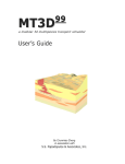
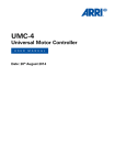
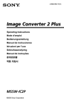
Application Example
The Application examples within this section where optimized for performance and system costs. Of course there
exists several steps in between which can be realized by the customer to fulfill the application specific needs.
+3V3
supply
+3V3
supply
1 RSSI
IF_OUT 28
2 VDDA
VDDRF 27
3 GNDA
PPRF 26
4,7 Ω
0.1µF
0.1µF
10 Ω
10 Ω
4 IF_IN
RFOUT 25
5 GND_IF
GNDRF 24
6 VDD5V
LNA_INP 23
7 VDDD
LNA_INN 22
Choke
ANT
GNDRF 21
8 VDDD1V5
0.1µF
0.1µF
0.1µF
TM 20
9 GNDD
10 PP0
NINT to μC
P_ON from μC
TDA5340
SDO 19
to μC
11 PP1
SDI 18
from μC
12 PP2
SCK 17
from μC
13 P_ON
NCS 16
from μC
14 XTAL1
XTAL2 15
21.948717 MHz XTAL
Figure 1
Application Example optimized for System Costs (3V3 Supply)
User Manual
12
Revision 1.0, 17.02.2012
TDA5340
SmartLEWISTM TRX
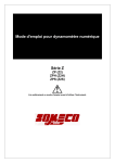
Introduction
10.7 MHz CERFIL
control line
+5V
supply
1 RSSI
IF_OUT 28
2 VDDA
VDDRF 27
3 GNDA
PPRF 26
control line
0.1µF
0.470 µF
4 IF_IN
RFOUT 25
5 GND_IF
GNDRF 24
Choke
ANT
Antenna Switch
2.2 Ω
10µF
0.1µF
6 VDD5V
LNA_INP 23
7 VDDD
LNA_INN 22
0.1µF
8 VDDD1V5
SAW
Filter
GNDRF 21
0.1µF
9 GNDD
10 PP0
NINT to μC
P_ON from μC
TM 20
TDA5340
SDO 19
to μC
11 PP1
SDI 18
from μC
12 PP2
SCK 17
from μC
13 P_ON
NCS 16
from μC
14 XTAL1
XTAL2 15
21.948717 MHz XTAL
Figure 2
Application Example optimized for RF performance (5V Supply)
User Manual
13
Revision 1.0, 17.02.2012
TDA5340
SmartLEWISTM TRX
Introduction
1.4
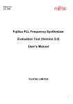
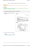
Pin Configuration
The pin configuration of the TDA5340, which is based on the PG-TSSOP-28 package, is shown in Figure 3.
Figure 3
PPRF_RSSI
1
28
IF_OUT
VDDA
2
27
VDDRF
GNDA
3
26
PPRF
IF_IN
4
25
RFOUT
GNDIF
5
24
GNDRF
VDD5V
6
23
LNA_INP
VDDD
7
22
LNA_INN
VDDD1V5
8
21
GNDRF
GNDD
9
20
TM
PP0
10
19
SDO
PP1
11
18
SDI
PP2
12
17
SCK
P_ON
13
16
NCS
XTAL1
14
15
XTAL2
TDA5340
Pin-Out
User Manual
14
Revision 1.0, 17.02.2012
TDA5340
SmartLEWISTM TRX
Introduction
1.5
Pin Definition
Table 1
Pin Definition and Function
Pin Nr
Pad Name
1
PPRF_RSSI
Equivalent I/O Schematic
Function
VDDRF
VDDA
VDDA
vm_p
500Ω
RSSI
vm_n
GNDA
GNDA
GNDRF
2
VDDA
Analog output
Digital output with weak driver
capability, always in 3V domain
RX_RUN, NINT,
ANT_EXTSW1,
ANT_EXTSW1, DATA,
DATA_MATCHFIL, CH_DATA,
CH_STR, RXD, RXSTR,
TXSTR and TRISTATE are
programmable via SFR
default: TRISTATE
Analog input
Analog supply
VDD5V
+
VReg
=
-
VDDA
GNDA
3
GNDA
Analog Ground
VDDA
GNDA
analog ground
User Manual
15
Revision 1.0, 17.02.2012
TDA5340
SmartLEWISTM TRX
Introduction
Table 1
Pin Definition and Function
Pin Nr
Pad Name
4
IF_IN
Equivalent I/O Schematic
Function
VDDA
VDDA
not sel_inp
mimCAP 10p
320Ω
IF_IN
Analog input
IF mixer input
sel_inp
GNDIF
GNDIF
VDDA
NAND2
GNDIF
5
GNDIF
Analog Ground
GNDIF
GNDA
6
VDD5V
Analog input
5 Volt supply input
VDD5V
GNDD GNDD
5V supply
7
VDDD
Analog input
digital supply input
VDD5V
+
VReg
=
-
VDDD
GNDD
User Manual
16
Revision 1.0, 17.02.2012
TDA5340
SmartLEWISTM TRX
Introduction
Table 1
Pin Definition and Function
Pin Nr
Pad Name
8
VDDD1V5
Equivalent I/O Schematic
Function
Analog output
1.5V regulator
VDDD
+
VReg
=
-
GNDD
9
VDD1V5
GNDD
Digital ground
VDDD
GNDD
10
PP0
VDD5V
VDD5V
vm_p
PP0-PP2
vm_n
Digital output
CLK_OUT, RX_RUN, NINT,
ANT_EXTSW1,
ANT_EXTSW1, DATA,
DATA_MATCHFIL, CH_DATA,
CH_STR, RXD, RXSTR,
TXSTR and TRISTATE are
programmable via SFR
default: CLK_OUT
GNDD
GNDD
11
PP1
User Manual
same as PP0
Digital output
CLK_OUT, RX_RUN, NINT,
ANT_EXTSW1,
ANT_EXTSW1, DATA,
DATA_MATCHFIL, CH_DATA,
CH_STR, RXD, RXSTR,
TXSTR and TRISTATE are
programmable via SFR
default: DATA
17
Revision 1.0, 17.02.2012
TDA5340
SmartLEWISTM TRX
Introduction
Table 1
Pin Definition and Function
Pin Nr
Pad Name
Equivalent I/O Schematic
Function
12
PP2
same as PP0
Digital output
CLK_OUT, RX_RUN, NINT,
ANT_EXTSW1,
ANT_EXTSW1, DATA,
DATA_MATCHFIL, CH_DATA,
CH_STR, RXD, RXSTR,
TXSTR and TRISTATE are
programmable via SFR
default: NINT
13
P_ON
VDD5V
500Ω
P-ON
GNDD
14
Digital input
power-on reset
VDDD
GNDD
XTAL1
Analog input
crystal oscillator input
VDDD
VDDD
XTAL1
....
GNDD
15
GNDD
GNDD
XTAL2
VDDD
Analog output
crystal oscillator output
VDDD
XTAL2
....
GNDD
16
GNDD
GNDD
NCS
VDD5V
VDDD
500Ω
NCS
GNDD
User Manual
Digital input
SPI Not Chip select
GNDD
18
Revision 1.0, 17.02.2012
TDA5340
SmartLEWISTM TRX
Introduction
Table 1
Pin Definition and Function
Pin Nr
Pad Name
17
SCK
Equivalent I/O Schematic
Function
VDD5V
500Ω
SCK
GNDD
18
SDI
GNDD
VDD5V
Digital input
SPI data in
VDDD
500Ω
SDI
GNDD
19
Digital input
SPI clock
VDDD
GNDD
SDO
Digital output
SPI data out
VDD5V
VDD5V
vm_p
SDO
noRC
vm_n
GNDD
GNDD
20
TM
VDD5V
VDDD
500Ω
TM
GNDD
User Manual
Digital input
connect to digital ground
GNDD
19
Revision 1.0, 17.02.2012
TDA5340
SmartLEWISTM TRX
Introduction
Table 1
Pin Definition and Function
Pin Nr
Pad Name
21
GNDRF
Equivalent I/O Schematic
Function
Analog ground
VDDRF
GNDRF
22
LNA_INN
Analog input
- RF input
LNA_INN
SHORT_LNA_INN
GNDRF
23
GNDRF
LNA_INP
Analog input
+RF input
LNA_INP
SHORT_LNA_INP
GNDRF
24
GNDRF
GNDRF
Analog ground
VDDRF
GNDRF
25
RFOUT
RFOUT
Analog output
power amplifier output
GNDRF
User Manual
20
Revision 1.0, 17.02.2012
TDA5340
SmartLEWISTM TRX
Introduction
Table 1
Pin Definition and Function
Pin Nr
Pad Name
26
PPRF
Equivalent I/O Schematic
Function
VDDRF
VDDRF
vm_p
PPRF
vm_n
Digital output
always in 3V domain
RX_RUN, NINT,
ANT_EXTSW1,
ANT_EXTSW1, DATA,
DATA_MATCHFIL, CH_DATA,
CH_STR, RXD, RXSTR,
TXSTR and TRISTATE are
programmable via SFR
default: TRISTATE
GNDRF
GNDRF
27
VDDRF
Analog input
RF supply
VDD5V
+
VReg
=
-
VDDRF
GNDRF
28
IF_OUT
VDDRF
VDDRF
Analog output
Mixer output
330Ω
IF-OUT
50Ω
3pF
GNDRF
User Manual
GNDRF
21
GNDRF
Revision 1.0, 17.02.2012
TDA5340
SmartLEWISTM TRX
Transceiver Architecture
2
Transceiver Architecture
The TDA5340 transceiver architecture is based on a super-heterodyne/low-IF, single or double down conversion
receiver in combination with a highly efficient Class C/E type power amplifier.
A fully integrated Sigma-Delta Fractional-N PLL Synthesizer covers the frequency bands 300-320 MHz, 415495 MHz, 863-960 MHz with a high frequency resolution, using only one VCO running at around 3.6 GHz. This
makes the IC most suitable for Multi-Band/Multi-Channel applications. For Multi-Channel applications a very good
channel separation is essential. To achieve the necessary high sensitivity and selectivity a double down
conversion super-heterodyne architecture is used. The first IF frequency is located around 10.7 MHz and the
second IF frequency around 274 kHz. For both IF frequencies an adjustment-free image frequency rejection
feature is realized. In the second IF domain the filtering is done with an on-chip third order bandpass polyphase
filter. A multi-stage bandpass limiter completes the RF/IF path of the receiver. For Single-Channel applications
with relaxed requirements to selectivity, a single down conversion low-IF scheme can be selected.
A very high efficient Class C/E Power amplifier with output levels of +14 dBm combined with a Gaussian Filter for
GFSK and amplitude ramping functions for shaped ASK is implemented. A high resolution power adjustment can
be done to trim the output power for highest system power savings. The data can be either shifted out of an onchip transmit FIFO or directly provided on an input pin.
An RSSI generator delivers a DC signal proportional to the applied input power and is also used as an ASK
demodulator. Via an anti-aliasing filter this signal feeds an ADC with 10 bits resolution.The harmonic suppressed
limiter output signal feeds a digital FSK demodulator. This block demodulates the FSK data and delivers an AFC
signal which controls the divider factor of the PLL synthesizer. A digital receiver, which comprises RSSI peak
detectors, a matched data filter, a clock and data recovery, a data slicer, a frame synchronization and a data FIFO,
decodes the received ASK or FSK data stream. The recovered data and clock signals are accessible via 2
separate pins. The FIFO data buffer is accessible via the SPI bus interface.The crystal oscillator serves as the
reference frequency for the PLL phase detector, the clock signal of the Sigma-Delta modulator and divided by two
as the 2nd local oscillator signal. To accelerate the start up time of the crystal oscillator two modes are selectable:
a Low Power Mode (with lower precision) and a High Precision Mode.
Features
•
•
•
•
•
•
•
•
Power Amplifier with up to 14 dBm output power
Sigma Delta PLL with a resolution down to 10.5 Hz
Receiver with integrated configurable IF-Filter and outstanding sensitivity performance
On-chip transmit/receive switch
Two receiver inputs supporting antenna diversity and multiband operation
4 pre-programmable configuration sets with self polling and channel scan capabilities
Autonomous scanning of up to 16 receive channels
Power ramping and Gaussian filtering of transmit data
User Manual
22
Revision 1.0, 17.02.2012
TDA5340
SmartLEWISTM TRX
Operating Modes
2.1
Functional Block Diagram
CER (opt.)
IF_OUT
IF_IN
BUF
RSSI
XTAL1
BUF
LNA
PA
PLL
ΣΔ
VDD
Temp
Div
by 2
XTAL2
fsys
fsys
Envelope
Shaping
Gauss Filter
Encoding
Baud Rate
Generator
TX FIFO
Interrupt Control
A
Finite State Machine
fsys
VDDRF
VDDA
P_ON
21.948
MHz
IR
IR
RF_OUT
Limiter
BPF
LNA_INP
LNA_INN
D
AFC / AGC
PDF /
FM Demodulator
Antenna
Diversity
RSSI
avg/peak
Data Filter
Polling Timer
Slicer / CDR
Decoding
RX FIFO
Power Supply
Port Pin Control
VDD5V, VDDD,
VDDD1V5
SPI Interface
PP0..PP2,
PPRF
Figure 4
TDA5340 Block Diagram
2.2
Block Overview
NCS, SDI,
SDO, SCK
The TDA5340 is separated into the following main blocks:
•
•
•
•
•
•
•
•
•
•
•
RF / IF Receiver
Power Amplifier
Crystal Oscillator and Clock Divider
Sigma-Delta Fractional-N PLL Synthesizer
ASK / FSK Demodulator inc. AFC and AGC
RSSI Peak Detector
Digital Baseband Receiver
Digital Baseband Transmitter
Power Supply Circuitry
System Interface
System Management Unit
3
Operating Modes
The transceiver has three different power saving modes, two receive modes and a transmit mode. The different
operating modes are used to adjust the transceiver functionality to the needs of the application. Depending on the
User Manual
23
Revision 1.0, 17.02.2012
TDA5340
SmartLEWISTM TRX
Operating Modes
used communication protocols the appropriate power saving mode can be selected. In the table below all different
modes are listed and corresponding to the modes the active blocks and current consumptions are shown.
Table 2
Operating Modes
Operating Mode
Transceiver Blocks
Dig. Vreg
Ana. Vreg XTAL
SFR
SPI
PLL
PA
RX
typ. Current
Consumption
Power Down
OFF
OFF
OFF
OFF
OFF
OFF
OFF
OFF
0.9 µA
Deep Sleep
ON
OFF
OFF
ON
OFF
OFF
OFF
OFF
7 µA
1)
ON
ON
OFF
OFF
OFF
40 µA2)
Sleep
ON
OFF
ON
Sleep ADC enabled
ON
ON
ON1)
ON
ON
OFF
OFF
OFF
1 mA
Transmit Ready
ON
ON
ON
ON
ON
ON
OFF
OFF
5.8 mA
Transmit Idle
ON
ON
ON
ON
ON
OFF
OFF
OFF
<3 mA
Transmit
ON
ON
ON
ON
ON
ON
ON
OFF
12.5 mA3)
Receive
ON
ON
ON
ON
ON
ON
OFF
ON
11.5 mA4)
1)
2)
3)
4)
selectable between XTAL in high or low precision mode
XTAL in low precision mode
10dBm Output power at 434MHz
single down conversion Mode (no external CER Filter used)
P_ON Pin
low
P_ON Pin
low
NCS line to low
+ SPI: disable
Deep Sleep
Deep Sleep
SPI: enable
Deep Sleep +
NCS line to high
P_ON Pin
low
P_ON Pin
high
SPI: Sleep
Mode
Sleep
SPI: Receive
Mode
SPI: Transmit
Mode
SPI: Sleep
Mode
Run Mode
Slave
Self Polling
Receive
Hold
Power Down
P_ON Pin
low
Ready
(TRM)
SPI: Transmit
Mode
Transmit
Idle
(TIM)
Run Mode
Self Polling
Active
(TAM)
SPI: Receive
Mode
Figure 5
Main State Diagram
3.1
Power Saving Modes
Three different power saving modes are supported by the TDA5340. Depending on the application requirements
like startup time and system current consumption the appropriate Power Saving Mode can be selected:
User Manual
24
Revision 1.0, 17.02.2012
TDA5340
SmartLEWISTM TRX
Operating Modes
•
•
•
Power Down Mode (PDM)
Deep Sleep Mode (DSM)
Sleep Mode (SM)
To enter the Power Down Mode (PDM), the P_ON Pin must be pulled to low potential. As a result the Special
Function Register (SFR) will be set to reset state and all voltage regulators will be switched off. This mode provides
the lowest current consumption but also requires the longest time to recover to active modes.
Before entering the Deep Sleep Mode (DSM) this mode must be enabled by setting the SFR bit DSLEEPEN in
the Chip Mode Control Register. To enter the DSM, pin NCS must be pulled to high potential. In the DSM the
Crystal Oscillator is switched off but all SFR content is retained. Waking up from DSM is initiated by pulling the
NCS pin to low potential again. After the end of the Crystal Oscillator start up time a system ready interrupt is
generated (see “Interrupt Generation Unit” on Page 50) and the DSLEEPEN bit in the Chip Mode Control
Register must be cleared to finally leave the DSM. The DSM can be only entered if the Sleep Mode is enabled.
In Sleep Mode the Crystal Oscillator is running and the digital domain is active but all analog parts are switched
off. The Sleep Mode is fully controlled by the MSEL bit group in the Chip Mode Control Register. The SM offers
the fastest switching time to active modes but with the expense of higher current consumption.
3.2
Transmit Modes
The Transmit (TX) Mode of the TDA5340 can be entered out of the Sleep and Receive Mode by changing the
MSEL bit group in the Chip Mode Control Register. In this Mode the transmitter will be enabled and the data will
be sent depending on the pre-configured settings.
Transmit (TX) Modes
•
•
•
TX Ready Mode (TRM)
TX Idle Mode (TIM)
TX Active Mode (TAM)
– TX FIFO Mode (TFM)
– TX Transparent Mode (TTM)
The state diagram in Figure 6 shows all possible start and stop combinations of the different transmit modes.
User Manual
25
Revision 1.0, 17.02.2012
TDA5340
SmartLEWISTM TRX
Operating Modes
Sleep
Receive
SPI:
TX mode
SPI:
TX mode
Init TX
SPI:
TX PLL init
TX ready
FIFO not
empty
Finish TX
with FIFO
empty
enabled
SPI:
Start Bit
SPI:
Transparent TX
command
TX ready
Interrupt
SPI:
TX FIFO
FIFO not
empty or
Start Bit
set
FIFO
empty
TX
FIFO empty
TX FIFO
empty
Interrupt
Figure 6
PLL cal.
finished
Go to Idle
after TX
enabled
TX
Transparent
TX PLL init
NCS line
to high
TX idle
TX fail if
Failsafe
enabled
Transmit Modes
To enter the TX Mode the transceiver needs to start first the analog voltage regulators and the PLL. The host
controller needs to set the MSEL operating mode bit group in the chip mode control register to enter the TX Ready
Mode. The entrance of the TRM is indicated by an interrupt on the NINT line which shows the host controller that
the transmitter has finished the startup procedure.
The Transmit Active Mode (TAM) enables a continuous data transmission where the baseband data are
provided by the host controller or from the loaded on-chip transmit FIFO. The TAM must be entered out of the
TRM. This can be done via several methods:
•
•
•
The transparent TX command is entering the TX Transparent Mode while base band data must be provided
on the SDI line. (see “TX Transparent Mode” on Page 40)
The transceiver is configured in direct transmit mode. This means the Transmit Mode starts right after Transmit
Ready Mode as long the TX FIFO is not empty. (see “TX FIFO Modes” on Page 39)
The host controller is using the start bit mode of the transceiver. Within this mode the TFM is entered after
enabling the TX start bit in the transmit mode control register (TX Control Register).
After transmission of the data frame the TDA5340 either waits for retransmission in the Transmit Ready Mode
using the command listed above or enters the Transmit Idle Mode (TIM). Out of the TIM a very fast switch to other
modes (e.g. receive) is possible by changing the MSEL bit group in the Chip Mode Control Register . It is strongly
recommended to leave the TIM state as fast as possible which has to be initiated by the host controller to avoid
unnecessary high current consumption.
3.3
Receive Modes
The Receive Modes of the TDA5340 are designed to meet different requirements of the application.
The TDA5340 has three major receive operation modes, which are switched by MSEL bit group in the Chip Mode
Control Register and the SFR bit HOLD in the RX Control Register.
Receive Modes
•
Run Mode Slave Receive (RMS)
User Manual
26
Revision 1.0, 17.02.2012
TDA5340
SmartLEWISTM TRX
Operating Modes
•
•
•
Self Polling Mode Receive (SPM)
Run Mode Self Polling (RMSP)
Hold Mode (HM)
In RMS the receiver is always active which minimizes the preamble length of the transmit packet. The SPM can
be used to perform automatic channel switching and preamble detection. Furthermore the average receive current
consumption can be reduced significantly.
The following state diagram in Figure 7 shows the possible transitions within the Receive Mode.
Sleep
SPI:
RMS / SPM
Transmit
Analog
startup
Init RX
RMS Æ MSEL=10 B
Run Mode
Slave
SPI:
Hold Mode
SPI:
release Hold
Mode
Hold Mode
SPI:
RMS / SPM
SPMÆ MSEL = 01 B
Self Polling
Mode
End of
message
Time out
Timer
Wake up
criteria found
Run Mode
Self Polling
Figure 7
RX Main States
3.3.1
Run Mode Slave Receive (RMS)
In Run Mode Slave (RMS) the transceiver is able to continuously receive data which is consequently provided to
the host controller. Run Mode Slave is entered by setting the MSEL bit group in the Chip Mode Control Register.
The successful detection of a payload, message ID and/or a whole message (End of message) can be signaled
to the host micro controller via interrupts. For further details see “Interrupt Generation Unit” on Page 50
The configuration may be changed only in Sleep or in Hold Mode before returning to the previously selected
operation mode. This is necessary to restart the state machine with defined settings at a defined state. Otherwise
the state machine may show an undefined behaviour. Reconfiguration in Hold Mode is faster, because there is no
Start-Up sequence.
3.3.2
Hold Mode
The Hold Mode is used in RMS to reconfigure the SFR of the device without changing back to Sleep Mode to
avoid the time consuming startup procedure. To reconfigure the chip the SFR control bit HOLD in the RX Control
Register must be set. After reconfiguration in this state the SFR control bit HOLD must be cleared again. After
leaving the Hold Mode, the INIT state is entered and the receiver can work with the new settings. Be aware that
the time between changing the configuration and re initialization of the chip has to be at least 40us.
User Manual
27
Revision 1.0, 17.02.2012
TDA5340
SmartLEWISTM TRX
Operating Modes
FSM State
SPI Command
EOM-Check
Instruction Address
Write
CMC0
0x02
HOLD
Data
HOLD=1
INIT
Instruction Address
Data
Write
x_CHCFG (sel. other
0x02
channel)
Instruction Address
Write
CMC0
0x02
Wait till
SSync
Data
HOLD=0
12us @ 2.0MHz
40us
Figure 8
HOLD State Behavior (INITPLLHOLD disabled)
In case of large frequency steps, an additional VAC routine (VCO Automatic Calibration) has to be activated when
recovering from Hold Mode (INITPLLHOLD bit in RX Control Register). The maximum allowed frequency step in
Hold Mode without activation of VAC routine depends on the selected frequency band. The limits are +/- 1 MHz
for the 315 MHz band, +/- 1.5 MHz for the 434 MHz band and +/- 3 MHz for the 868/915 MHz band.
When this additional VAC routine is enabled, the TDA5340 starts initialization of the Digital Receiver block after
release from Hold Mode and an additional Channel Hop time.
FSM State
SPI Command
EOM-Check
Instruction Address
Write
CMC0
0x02
HOLD
Data
HOLD=1
Instruction Address
Data
Write
x_CHCFG (sel. other
0x02
channel)
VAC
Instruction Address
Write
CMC0
0x02
VAC
INIT
Wait till
SSync
Data
HOLD=0
12us @ 2.0MHz
tChHop
40us
Figure 9
HOLD State Behavior (INITPLLHOLD enabled)
Hold Mode is only available in Run Mode Slave. Configuration changes in Self Polling Mode have to be done by
switching to SLEEP Mode and returning to Self Polling Mode after reconfiguration.
3.3.3
Self Polling Mode Receive (SPM)
In Self Polling Mode (SPM) the TDA5340 is autonomously toggling between Sleep Mode and receive mode. At
that time there is no processing load on the host micro controller. When a wake-up criterion has been found, an
interrupt can be generated and the TDA5340 mode will be changed to Run Mode Self Polling (RMSP). In RMSP
the receiver is searching for the payload data. The mode change back to SPM can be triggered by a successful
reception of the payload or by several programmable Time Out Timer (TOTIM) events. Detailed descriptions of
payload detection can be found in section “Frame Synchronization” on Page 95 and for the TOTIM in section
“Time Out Timer (TOTIM)” on Page 62.
The Polling Timer Unit controls the timing for scanning (On time) and sleeping (Off time, SPM_OFF). Up to four
independent configuration sets (A, B, C and D) can automatically be processed, thus enabling scanning from
different transmit sources. Additionally, up to 4 different frequency channels within each configuration may be
scanned to support Multi-Channel applications. For configuration of On and Off timings see also “Polling Timer”
on Page 60. So a autonomous scanning of up to 16 different frequency channels is supported.
The successful detection of a wake up criteria, payload, message ID and/or a whole message (End of message)
can be signaled to the host micro controller via interrupts. For further details see “Interrupt Generation Unit” on
Page 50
User Manual
28
Revision 1.0, 17.02.2012
TDA5340
SmartLEWISTM TRX
Operating Modes
Automatic Modulation Switching
In Self Polling Mode, the chip is able to automatically change the type of modulation after a wake-up criterion was
fulfilled in a received data stream. The type of modulation used in the different operational modes is selected by
the SFR control bit MT.
Multi-Channel in Self Polling Mode
As previously mentioned, in Self Polling Mode the TDA5340 allows RF scans on up to four RF channels per
configuration, this can be defined in the Channel Configuration Register. Channel frequencies are defined in
registers PLL MMD Integer Value Register Channel 1, PLL Fractional Division Ratio Register 0 Channel 1,
PLL Fractional Division Ratio Register 1 Channel 1 and PLL Fractional Division Ratio Register 2 Channel
1, where A can be replaced by B, C or D and C1 can be replaced by C2, C3 or C4 to access the different channels
and configurations.
Parallel Wake Up Search
While the TDA5340 is in Run Mode Self Polling, further Wake-ups would normally not be detected by the receiver.
If the functionality of a parallel Wake-up search during the search for a TSI is desired, this can be activated by the
PWUEN bit in Wake-Up Control Register. In this case the Wake-up search is not active during a recognized
payload and is only active after the first received payload frame. This feature can only be used, when modulation
type is the same for SPM and RMSP.
So after a reception of the EOM from the current payload, the parallel WU search can take place in this mode. The
WU search will be active after Symbol Sync has been detected.
Self Polling Modes
Four polling modes are available to fit the polling behavior to the expected wake-up patterns and to optimize power
consumption in Self Polling Mode.
The following 4 Polling Modes are available and can be configured via 2 bits in the configuration Self Polling
Mode Control Register:
•
•
•
•
Constant On-Off (COO)
Fast Fall Back to SLEEP (FFB)
– Ultra Fast Fall Back to SLEEP (UFFB)
Mixed Mode (MM)
Permanent Wake-Up Search (PWUS)
A detected wake-up data sequence or an actual value for RSSI or Signal Recognition (a combination of Signal
Detector and Noise Detector, see “Data Filter and Signal Detection” on Page 82) exceeding a certain
adjustable threshold forces the TDA5340 into Run Mode Self Polling.
In all modes the timing resolution is defined by the Reference Timer, which scales the incoming frequency
(fsys/64) corresponding to the value, which is defined in the Self Polling Mode Reference Timer Register.
Changing values of SPMRT helps to fit the final On-Off timing to the calculated ideal timing.
3.3.3.1
Constant On-Off Mode (COO)
In this mode there is a constant On and a constant Off time. Therefore also the resulting master period time is
constant.
When Single-Configuration is selected then only Configuration A is used. The number of RF channels is defined
in the Channel Configuration Register (Single-Channel or Multi-Channel Mode).
Multi-Configuration Mode allows reception of up to 4 different transmit sources or up to 16 RF channels. The
corresponding RF channels can be defined in the Channel Configuration Register, B_CHCFG, C_CHCFG and
D_CHCFG registers. In the case of Multi-Channel or combination of Multi-Channel and Multi-Configuration Mode,
User Manual
29
Revision 1.0, 17.02.2012
TDA5340
SmartLEWISTM TRX
Operating Modes
the configured On time is used for each RF channel in a configuration. The diagram below shows possible
scenarios.
Single Channel, Single Config
run mode
A
1
RX polling
sleep mode
TAON
Channels = 1
TMasterPeriod = TAON + TOFF
TOFF
TMasterPeriod
Multi Channel, Single Config
run mode
A
1
RX polling
sleep mode
A
2
A
3
T AON TAON TAON
Channels = m
TMasterPeriod = m*TAON + TOFF
TOFF
TMasterPeriod
Multi Channel, Multi Config
run mode
A
1
RX polling
sleep mode
A
2
A
3
B
1
T AON TAON TAON TBON
B
2
TBON
Channels Config A = m
Channels Config B = n
TMasterPeriod = m*TAON + n*T BON+ T OFF
T OFF
TMasterPeriod
Figure 10
Constant On-Off Time
3.3.3.2
Fast Fall Back to SLEEP (FFB)
This mode is used to switch off the receiver, if there is no RF signal, as quickly as possible to reduce power
consumption.
During the search for wake-up data, there is a check for the right data rate, to which the system can be
synchronized. If there is no synchronization to the programmed data rate within the so-called Sync Search Time
Out (SYSRCTO), the wake-up search for this channel is stopped. If synchronization to the data rate is possible
(and not lost again), the TDA5340 waits if the wake-up criterion is fulfilled. If the wake-up criterion is not fulfilled
(in worst case, if the last bit of an expected wake-up data pattern is wrong), the wake-up procedure for this channel
is stopped, and the TDA5340 tries to synchronize on the next channel, or falls back to sleep. That means that the
effective search time and, consequently, the receiver active time is significantly shorter, and power consumption
is reduced, when no input signal is present. Calculation of Sync Search Time Out can be found in “Clock and
Data Recovery (CDR)” on Page 88.
The On and Off time setting is different from the Constant On-Off Time Mode. The entire On time is defined in the
Self Polling Mode On Time Config A Register 0 and Self Polling Mode On Time Config A Register 1.
Regardless of the numbers of RF channels and whether or not Multi- or Single-Configuration is used, the On time
is defined with the Configuration A On-Timer. The deactivation of the receiver can happen at different times, but
this event does not influence the timer stage, because the On time is still the same. So the master period is
constant. The following scenarios are the same as before, but with Fast Fall Back to SLEEP.
User Manual
30
Revision 1.0, 17.02.2012
TDA5340
SmartLEWISTM TRX
Operating Modes
Single Channel, Single Config
run mode
RX polling A
1
sleep mode
TAON
Channels = 1
TMasterPeriod = TAON + TOFF
TOFF
TMasterPeriod
Multi Channel, Single Config
run mode
Channels = m
TMasterPeriod = TAON + TOFF
A A
RX polling A
1 2 3
sleep mode
TAON
TOFF
TMasterPeriod
Multi Channel, Multi Config
Channels Config A = m
Channels Config B = n
TMasterPeriod = TAON + T OFF
run mode
A A B B
RX polling A
1 2 3 1 2
sleep mode
T AON
TOFF
TMasterPeriod
Figure 11
Fast Fall Back to SLEEP
Only the following receive modes (see “Data Interface” on Page 35) can be used:
•
•
•
Packet Oriented FIFO Mode (POF)
Packet Oriented Transparent Payload Mode (POTP)
Transparent Mode - Chip Data and Strobe (TMCDS)
Ultra Fast Fall Back to Sleep (UFFB)
The needed time for detecting that no relevant transmission took place can be further reduced by using Ultrafast
Fall Back to SLEEP (UFFB). When there was no Wake-up on Level criterion fulfilled in UFFB Mode during the
Observation Time (TWULOT, see “Wake-Up Generator” on Page 90), then the system goes back to SLEEP (or
to next config/channel). This can further reduce the receiver active time, when no data is available. When Wakeup on Level criterion was fulfilled, then the system proceeds with normal FFB functionality (SYSRCTO, optional
Wake-up data criterion).
Ultrafast Fall Back to SLEEP is working, when a Wake-up on Data criterion is selected, the UFFBLCOO bit is
enabled and FFB or PWUS mode is selected. The UFFB level criterion can be selected in the Wake-Up Control
Register.
3.3.3.3
Mixed Mode (MM, Const On-Off & Fast Fall Back to SLEEP)
This mode combines Constant-On Time and Fast Fall Back to SLEEP within different configuration sets: Cfg.A:
COO; Cfg.B: FFB; Cfg.C: FFB; Cfg.D: FFB
TON for Configuration A is always calculated according to Const On-Off rules.
TON for Configuration B, C and D is always calculated according to Fast Fall Back to SLEEP rules.
In Mixed Mode the On time of the first configuration within the FFB group is used. Below there are shown the same
scenarios as before, but now for Mixed Mode. Note that Single-Configuration can be set, but is not recommended
in Mixed Mode.
User Manual
31
Revision 1.0, 17.02.2012
TDA5340
SmartLEWISTM TRX
Operating Modes
Single Channel, Single Config
run mode
A
1
RX polling
sleep mode
TAON
Channels = 1
TMasterPeriod = TAON + TBON + TOFF
TOFF
TBON
TMasterPeriod
Multi Channel, Single Config
run mode
A
1
RX polling
sleep mode
A
2
A
3
TAON TAON T AON
TBON
Channels = m
TMasterPeriod = m*TAON + T BON + TOFF
TOFF
TMasterPeriod
Multi Channel, Multi Config
run mode
A
1
RX polling
sleep mode
A
2
A
3
TAON TAON T AON
B
1
B
2
TBON
Channels Config A = m
Channels Config B = n
TMasterPeriod = m*TAON + T BON+ TOFF
TOFF
TMasterPeriod
Figure 12
Mixed Mode
Only the following receive modes (see “Data Interface” on Page 35) can be used:
•
•
•
Packet Oriented FIFO Mode (POF)
Packet Oriented Transparent Payload Mode (POTP)
Transparent Mode - Chip Data and Strobe (TMCDS)
3.3.3.4
Permanent Wake-Up Search (PWUS)
In this mode the receiver will work in Fast Fall Back Mode, but it will not go back to the SLEEP state after the last
channel has been searched. Instead, it will start again from the beginning (Configuration A, RF Channel 1) until
the On time has elapsed. The timing calculation can be seen in Figure 13. Ultrafast Fall Back to SLEEP
functionality can be used as well.
User Manual
32
Revision 1.0, 17.02.2012
TDA5340
SmartLEWISTM TRX
System Interface
Single Channel , Single Config
run mode
A A A A AA
RX polling 1 1 1 1 1 1
sleep mode
TAO N
Channels = 1
TMasterPeriod = TAON + TOFF
TOFF
TMasterPeriod
Multi Channel , Single Config
run mode
A A AA A A
RX polling A
1 2 3 12 3 1
sleep mode
TAO N
Channels = m
TMasterPeriod = TAON + TOFF
TOFF
TMasterPeriod
Multi Channel , Multi Config
run mode
Channels Config A = m
Channels Config B = n
TMasterPeriod = TAON+ TOFF
AA A B B A A
RX polling 1 2 3 1 2 1 2
sleep mode
TAON
TOFF
TMasterPeriod
Figure 13
Permanent Wake-Up Search
Only the following receive modes (see “Data Interface” on Page 35) can be used:
•
•
•
Packet Oriented FIFO Mode (POF)
Packet Oriented Transparent Payload Mode (POTP)
Transparent Mode - Chip Data and Strobe (TMCDS)
4
System Interface
In most applications, the TDA5340 transceiver IC is attached to an external micro controller. This so-called
Application Controller executes a firmware which governs the TDA5340 by reading data from the transceiver when
data has been received on the RF channel or write data to the transmit portion if some data needs to be sent. The
firmware needs to handle the switching between receive and transmit mode and also the intialization of the
transceiver device. The TDA5340 features an easy to use System Interface, which is described in this chapter.
Transparent Mode
The TDA5340 supports two levels of integration. In the most elementary fashion, it provides a rather rudimentary
interface.
The incoming RF signal is demodulated and the corresponding data is made available to the Application
Controller. Optionally, a chip clock is generated by the TDA5340.
The Application Controller can provide the baseband data to a single input pin which is modulated and amplified
via the PLL and Power amplifier.
Since the data signal is always directly the baseband representation of the RF signal, we call this mode the
Transparent Mode. The usage of the Transparent Mode will be described in Chapter 4.3.2 for the receive mode
and in Chapter 4.3.4 for the transmit mode.
User Manual
33
Revision 1.0, 17.02.2012
TDA5340
SmartLEWISTM TRX
System Interface
Packet Oriented Mode
Alternatively, the TDA5340 features the so-called Packet Oriented Mode which supports the autonomous
reception and transmission of data telegrams. The Packet Oriented Mode provides a high-level System Interface
which greatly simplifies the integration of the transceiver in data-centric applications. In Packet Oriented Mode, the
data interface is based on chunks of synchronous data which are received in packets. In the easiest way, the
Application Controller only reacts on the synchronous data it receives. The receiver autonomously handles the line
decoding and the deframing of these data, and supports the timed reception of packets. Data is buffered in a
receive FIFO and can be read out via the data interface. Further, the receiver provides support for the identification
of wake-up signals. Details on the usage of the Packet Oriented Mode of the receiver are given in Chapter 4.3.1
for the receive mode and in Chapter 4.3.3 for the transmit portion.
4.1
Interfacing to the TDA5340
The TDA5340 is interfacing with an application by three logical interfaces, see Figure 14. The RF/IF interface
handles the transmission of RF signals and is responsible for the modulation and demodulation. Its physical
implementation has been described in “RF / IF Receiver” on Page 55, “Receiver Baseband” on Page 69, for
the receiver and in “Transmitter” on Page 58, “Transmitter Baseband” on Page 67 for the transmitter. The
other two logical interfaces establish the connection to the Application Controller. Note that due to the high level
of integration of the transceiver, these interfaces impose minor requirements on the Application Controller, which
can be as simple as an 8-bit micro controller operated at low clock rate. As will be shown later, the physical
implementation of the data interface depends on whether the transceiver is operating in Packet Oriented or in
Transparent Mode. For the sake of clarity, the communication between the TDA5340 and the Application
Controller is split into control flow and data flow. This separation leads to an independent definition of the data
interface and the control interface, respectively.
RF interface
RX data
TX data
SPI &
dig. Out
TDA5340
SPI /
dig. In/Out
data interface
configuration
status & alerts
Application
Controller
(µC)
control interface
Figure 14
Logical and electrical System Interfaces of the TDA5340
4.2
Control Interface
The control interface is used in order to configure the TDA5340 after start-up or to re-configure it during run-time,
as well as to properly react on changes in the status of the transceiver in the Application Controller’s firmware. The
control interface offers a bi-directional communication link by which
•
•
•
configuration data is sent from the Application Controller to the TDA5340,
the transceiver provides status information (e.g. the status of a data reception) as response to a request it
has received from the Application Controller and the
TDA5340 autonomously alerts the Application Controller that a certain, configurable event has occurred (e.g.
that a packet has been received successfully, the FIFO buffer needs a reload).
Configuration and status information are sent via the 4-wire SPI interface as described in “Digital Control (4-wire
SPI Bus)” on Page 41. The configuration data determines the behavior of the transceiver, which comprises
•
scheduling the inactive power-saving modes as well as the active receive / transmit modes,
User Manual
34
Revision 1.0, 17.02.2012
TDA5340
SmartLEWISTM TRX
System Interface
•
•
selecting the properties of the RF/IF interface configuration (e.g. carrier frequency selection, filter settings),
configuring the properties of the frames.
configuring the properties of the frames (e.g. wake-up patterns, Telegram Start Identifier (TSI), and optionally
specifying the position, format and content of patterns within packets that stimulate a certain, configurable
alerting behavior (Message ID)).
Note that the TDA5340 transceiver IC supports reception of multiple configuration sets on multiple channels in a
time-based manner without reconfiguration. Thus, the RF/IF interface as well as the frame format properties
support alternative settings, which can be activated autonomously by the transceiver as part of the scheduling
process.
In contrast to the high-level interface used for communicating configuration instructions and status information,
alerts are emitted by the transceiver on a digital output pin that may trigger external interrupts in the Application
Controller. Note that the alerting conditions as well as the polarity of the output pin are configurable, see “Interrupt
Generation Unit” on Page 50.
4.3
Data Interface
The data interface between the Application Controller and the TDA5340 transceiver IC is used for the transport of
the received and transmitted data, see Figure 14. The physical implementation as well as the features of the data
interface depend on the selected mode of operation.
There are 5 possible receive modes:
•
•
•
•
•
Packet Oriented FIFO Mode (POF)
Packet Oriented Transparent Payload Mode (POTP)
Transparent Mode - Chip Data and Strobe (TMCDS)
Transparent Mode - Matched Filter (TMMF)
Transparent Mode - Raw Data Slicer (TMRDS)
Access points for these receive modes can be seen in Figure 58.
The possible combinations of receive modes and polling mode setup is noted in Figure 15.
Const ON-OFF
WU on Level criterion
WU on data criterion
Signal
Random, Equal,
Recognition
Sync
Pattern
RSSI
Self Polling Mode
RX Mode
- available signal
POF
- FIFO
POTP
- RXD
- RXSTR
TMCDS
- CH_DATA
- CH_STR
TMMF
- DATA_MATCHFIL
TMRDS
- DATA
Fast Fall Back (UFFB), Mixed, PWUS
WU on Level criterion
WU on data criterion
Signal
Random, Equal,
Recognition
Sync
Pattern
RSSI
-
-
-
-
-
-
-
Legend:
Figure 15
available
not available
Receive Modes
There are 4 possible transmit modes:
•
•
•
•
Start Bit FIFO Mode (SBF)
Direct FIFO Mode (DF)
Synchronous Transparent Mode (STM)
Asynchronous Transparent Mode (ASTM)
User Manual
35
Revision 1.0, 17.02.2012
TDA5340
SmartLEWISTM TRX
System Interface
4.3.1
Packet Oriented Receive Modes
The TDA5340 features the so-called Packet Oriented Mode which supports the autonomous reception of data
telegrams. The Packet Oriented Mode provides a high-level System Interface which greatly simplifies the
integration of the transceiver in data-centric applications. In Packet Oriented Mode, the data interface is based on
chunks of synchronous data which are received in packets. In the easiest way, the Application Controller only
reacts on the synchronous data it receives. The receiver autonomously handles the line decoding and the de
framing of these data, and supports the timed reception of packets. Data is buffered in a receive FIFO and can be
read out via the data interface. Further, the receiver provides support for the identification of wake-up signals.
Packet Oriented FIFO Mode (POF)
In Packet Oriented FIFO Mode, data is transferred via the 4-wire SPI bus. During receive operation, the incoming
RF signal is demodulated in the RF/IF interface, the line decoding is performed and the data, of which wake-up
frames, data frame headers and optional footers have been stripped off, is stored in the RX FIFO. Then, the
received data can be read from the RX FIFO using the “read FIFO” command described in Chapter 4.5 and
Chapter 4.4. The data which is read from the RX FIFO is accompanied by information which contains the status
of the respective receive operation. Note that the availability of received data packets is communicated via alerts
in the control interface.
RF Interface
data
interface
line decoder
framer
RX FIFO
RX data
bit
synchronizer
Application Controller
TDA5340
scheduler
Figure 16
Data interface for the Packet Oriented FIFO Mode
Packet Oriented Transparent Payload Mode (POTP)
Packet Oriented Transparent Payload Mode (POTP) This mode is very similar to POF Mode as data which is going
into FIFO is also available via RXD and RXSTR signals (see Chapter 4.7).
line decoder
framer
RX FIFO
data
interface
bit
synchronizer
RX data
Strobe
Application Controller
RF Interface
TDA5340
scheduler
Figure 17
Data interface for the Packet Oriented Transparent Payload Mode
In the TDA5340, there are specific digital output lines (PPx pin) for the Bi-phase decoded data and an appropriate
Strobe signal. During inactivity of the receiver, the line is in default mode switched to low. In default mode the
User Manual
36
Revision 1.0, 17.02.2012
TDA5340
SmartLEWISTM TRX
System Interface
Strobe signal is active high and has a delay of TBIT/16 relative to the data bit and a duration of TBIT/2. The polarity
of the Strobe signal is programmable, this can be done via PPx Port Configuration Register .
Dn
RXD
Dn+1
RXSTR
TBIT/16
TBIT/2
Figure 18
Timing of the Packet Oriented Transparent Payload Mode
4.3.2
Transparent Receive Modes
The receiver’s simple plain data interface in this Transparent Mode is shown in Figure 19. In this mode, the
demodulated data signal is made directly available on the data output pin of the data interface. The demodulated
received data of the TDA5340 can be provided without any additional information of the frame structure. The
Transparent Mode has two main subgroups which can be distinguished by the usage of the Clock Data Recovery
(CDR) block. By using the CDR the TDA5340 provides the baseband data with the recovered encoding data clock.
Transparent Mode - Chip Data and Strobe (TMCDS)
The chip data and chip clock represents the recovered baseband data and clock of the CDR. Note that a sensible
chip clock can only be generated if the selected line encoding exhibits a constant chip rate. The chip clock
generation can be significantly improved by using a run-in signal of alternating one-zero chips (maximum number
of transitions within a data stream).
RF Interface
RX data
RX chip strobe
bit
synchronizer
Application Controller
data
interface
TDA5340
scheduler
Figure 19
Data interface for the Transparent Mode - Chip Data and Strobe
In the TDA5340, there is a specific digital output line for the chip clock estimate as well as for the data output line,
which delivers the encoded chip data. During inactivity of the receiver, the line is in default mode switched to low.
The PPx pin provides the estimated chip clock, if CH_STR is selected. Further details are given in Chapter 4.7.
In default mode the CH_STR signal is active high and has a delay of TCHIP/8 relative to the data chip and a
duration of TCHIP/2. The polarity of the CH_STR signal is programmable, this can be done via PPx Port
Configuration Register.
User Manual
37
Revision 1.0, 17.02.2012
TDA5340
SmartLEWISTM TRX
System Interface
Dn
CH_DATA
Dn+1
CH_STR
TCHIP/8
Figure 20
TCHIP/2
Timing of the Transparent Mode - Chip Data and Strobe
Transparent Mode - Matched Filter (TMMF)
The received data after the Matched Filter (Two-Chip Matched Filter) with an additional SIGN function is provided
via the DATA_MATCHFIL signal (PPx pin). In this mode sensitivity measurements with ideal data clock can be
performed very simple. For further details see the block diagram in Figure 58.
Sensitivity in this transparent mode significantly depends on the implemented clock and data recovery algorithm
of the user software in the application controller.
data
interface
RF Interface
RX data
Application Controller
TDA5340
scheduler
Figure 21
Data interface for the Transparent Modes TMMF / TMRDS
Transparent Mode - Raw Data Slicer (TMRDS)
This mode supports processing of data even without bi-phase encoding by providing the received data via the
One-Chip Matched Filter on the DATA signal (PPx pin). See more details in the block diagram in Figure 58.
Sensitivity in this transparent mode significantly depends on the implemented clock and data recovery algorithm
of the user software in the application controller. The data interface can be seen from Figure 20.
Self Polling mode is possible as well, but only Constant On-Off Mode and Wakeup on RSSI makes sense. Assume
one of the TDA5340 configurations (e.g. Configuration B) is set for external data processing mode. See also
example in Figure 22. The needed On time (latency through TDA5340) is configured in the corresponding On time
registers of the chip. The interrupt for Wake-Up Config B (WUB) is enabled and suitable RSSI thresholds are set.
If the RSSI signal is in a valid threshold area, the TDA5340 changes to Run Mode Self Polling and an interrupt
can be signaled to the Application Controller. In case the RSSI signal is outside the valid threshold area, the chip
stays in Self Polling Mode and the external controller gets no interrupt (as the desired RSSI level is not reached).
It should be mentioned that all Time-out Timers (TOTIMs) should be disabled in the configuration set of the
external processing mode as the micro controller takes over the control (see SFR bit group EXTPROC in the
Channel Configuration Register).
It is recommended to put this external configuration at the end of the On time within the polling cycle (so right
before the Off time). This is helpful when using the “EXTTOTIM” command (go to Self Polling Mode, next
programmed channel or Configuration A). When the external configuration is the last configuration before the Off
time, then the next programmed channel within the polling cycle would be the sequence of the Off time. When data
User Manual
38
Revision 1.0, 17.02.2012
TDA5340
SmartLEWISTM TRX
System Interface
is available and the RSSI is within a valid threshold area, an interrupt is generated (NINT). So the Application
Controller can process the data and decide about valid data.
In case the controller decides that wrong data was sent, the micro controller can send the register command
“EXTTOTIM” (see External Processing Command Register register). When the micro controller detects valid
data, then the controller can send the register command “EXTEOM found” (see External Processing Command
Register ) after completing the data reception.
The functionality described above can also be used for other receive modes (mainly TMMF, TMCDS), where the
external micro controller takes on responsibility for further data processing.
Good input signal
Wrong input signal
No input signal
SelfPolling Mode
SelfPolling scenario
Sleep Mode
Figure 22
ConfigA
ConfigB
OFF-time
RSSI level too low Î
Chip stays in Self Polling Mode
and sends no interrupt
Interrupt signal
for RSSI
RunMode SelfPolling
SelfPolling / Sleep
Interrupt signal
for RSSI
RunMode SelfPolling
µC detects invalid data and sends
„EXTTOTIM“Î goto SPM
SelfPolling / Sleep
Interrupt signal
for RSSI
µC finished data reception,
sends „EXTEOM found“
RunMode SelfPolling
SelfPolling / Sleep
External Data Processing
The SFR bit group EXTPROC in the Channel Configuration Register can be activated for each configuration set
for an easier handling of external data processing by the Application Controller. Depending on the intended
transparent receive mode an activation of this function means:
•
•
•
•
•
Data path in front of Framer Unit is no longer closed (so that no data is going into Framer Unit accidentally)
Interrupts for FSync, MID and EOM are deactivated internally
Some/all TOTIM counters are deactivated
Some/all Wake-up on Data Criteria are disabled
Wake-up on Signal Recognition is/is not disabled
4.3.3
TX FIFO Modes
The transmit FIFO can be used to reduce the real-time requirements of the host Micro controller. The transmit
FIFO can be loaded with a SPI command which is described in Figure 30.
We distinguish between Start Bit FIFO Mode (SBF) and Direct FIFO Mode (DF).
User Manual
39
Revision 1.0, 17.02.2012
TDA5340
SmartLEWISTM TRX
System Interface
Direct FIFO Mode (DF)
The Direct FIFO Mode enables the fastest transition from Init TX state to TX FIFO state. The transmitter will start
if a FIFO content is loaded right after the PLL settling time (TX Ready Mode) to shift out the FIFO content with the
pre configured output power, modulation scheme, center frequency, data rate and coding. By reloading the TX
FIFO the transmission will continue as long the FIFO is not empty. After sending the last Bit /Chip out of the FIFO
an interrupt can be generated to signal the host controller that the transmission of the FIFO content has finished.
The TDA5340 either waits for a refill of the TX FIFO in the TX FIFO empty state and sends out the last Bit / Chip
of the FIFO content as long as a new FIFO content is loaded.
If the TX Idle transition is enabled the Transceiver will go immediately after the TX empty interrupt into the TX Idle
state and waits for a user interaction (SPI access) which can be TX PLL initialization or a change to a other mode.
With the enabled finish transmission with TX FIFO Empty bit (see TX Control Register) the transceiver will wait
for restart of the transmission in the TX Ready state, the FIFO Empty and TX Ready interrupt flags are set in the
Interrupt Status Register 2.
Start Bit FIFO Mode (SBF)
If the FIFO is already loaded the transmission start only after setting the TX start bit in the TX Control Register.
The SBF mode can be used to enable exact timings of the transmitter.
By reloading the TX FIFO the transmission will continue as long as the FIFO is not empty. After sending the last
Bit /Chip out of the FIFO a interrupt can be generated to signal the host controller that the transmission of the FIFO
content has finished.
The TDA5340 either waits for a refill of the TX FIFO in the TX FIFO Empty state and sends out the last Bit / Chip
of the FIFO content as long as the start bit is set again in the TX Control Register.
After the TX Empty interrupt the Transceiver will go immediately into the the TX Idle state if the TX idle transition
is enabled and waits for a user interaction (SPI access) which can be TX PLL initialization or a change to another
mode.
With the enabled finish transmission with FIFO Empty bit the transceiver will wait for restart of the transmission in
the TX Ready state, the FIFO Empty and TX Ready interrupt flags are set in the Interrupt Status Register 2.
4.3.4
TX Transparent Mode
The transparent mode can be also subdivided into a synchronous and asynchronous transparent mode. In
transparent mode the data transmission is started with the transparent TX SPI command (see Figure 31
“Transparent TX Command” on Page 44).
Synchronous Transparent Mode
The synchronous transparent mode utilize a the on-chip baud rate generation unit to synchronize the incoming
data stream. The baud rate generator can be programmed via a 16 Bit word which is a dividing factor of the Crystal
frequency. The baseband data has to be synchronized with the baud rate strobe and provided on the SDI line (Pin
18), during the transmission the NCS line must be low. The TDA5340 can either executes a coding of the input
data (coded synchronous transparent mode) or shifts the data provided on the SDI line directly to the modulator
(synchronous NRZ mode).
The transmission is terminated by releasing the NCS line to high but the power amplifier is disabled after
transmitting of the complete last Bit / Chip. The Picture below shows the produced baseband data by using the
Synchronous Transparent Mode.
User Manual
40
Revision 1.0, 17.02.2012
TDA5340
SmartLEWISTM TRX
System Interface
NCS
SCK static to reduce noise/ SCK running incr. noise
SCK
SDI
data item 1
I7
I6
I5
I4
I3
I2
I1
Instruction wrt0/1
SDO
data item 2
data item 3
data item 4
data item n
I0
‚0' when wrt0 else ‚1'
high impedance Z
PPx
Baud rate generator
Manchester coded
baseband data
PA enable
Figure 23
Synchronous Transparent Mode
Asynchronous Transparent Mode
In some applications a change of data rate within one transmission is necessary. In this case the asynchronous
transparent mode has to be used. The data which are provided on the SDI line are directly modulated.
NCS
SCK static to reduce noise/ SCK running incr. noise
SCK
SDI
data item 1 data item 2 data item 3 data item 4
I7
I6
I5
I4
I3
I2
Instruction wrt0/1
SDO
I1
data item n-1 data item n
I0
‚0' when wrt0 else ‚1'
high impedance Z
Base band data
PA enable
Figure 24
Asynchronous Transparent Mode
Attention: If BT of Gaussian filter is less than 0.5, data edge uncertainties may occur.
4.4
Digital Control (4-wire SPI Bus)
The control interface used for device control and data transmission is a 4-wire SPI interface.
•
•
•
•
NCS - select input, active low
SDI
- data input
SDO - data output
SCK - clock input: Data bits on SDI are read in at rising SCK edges and written out on SDO at falling SCK
edges.
Level Definition:
•
•
logic 0 = low voltage level
logic 1 = high voltage level
Note: It is possible to send multiple frames while the device is selected. It is also possible to change the access
mode while the device is selected by sending a different instruction.
Note: In all bus transfers MSB is sent first, except for the received data read from the FIFO. There the bit order is
given as first bit received is first bit transferred via the bus.
User Manual
41
Revision 1.0, 17.02.2012
TDA5340
SmartLEWISTM TRX
System Interface
Table 3
Instruction Set
Instruction
Description
Instruction
Format
WRB
Write to chip in Burst mode
0x01
WR
Write to chip
0x02
RD
Read from chip
0x03
RDF
Read FIFO from chip
0x04
RDB
Read from chip in Burst mode
0x05
WRF
Write FIFO
0x06
WRT0
Write transparent transmit data 0x08
with starting low data
WRT1
Write transparent transmit data 0x07
with starting high data
Write Command
To write to the device, the SPI master has to select the SPI slave unit first. Therefore, the master must set the NCS
line to low. After this, the instruction byte and the address byte are shifted in on SDI and stored in the internal
instruction and address register. The following data byte is then stored at this address. After completing the writing
operation, either the master sets the NCS line to high or continues with another SPI command. Additionally the
received address byte is stored into the SPI Address Tracer Register and the received data byte is stored into
the SPI Data Tracer Register. These two trace registers are readable.Therefore, an external controller is able to
check the correct address and data transmission by reading out these two registers after each write instruction.
The trace registers are updated at every write instruction, so only the last transmission can be checked by a read
out of these two registers.
NCS
Frame
1
8
1
Frame
8
1
8
1
8
1
8
1
8
SCK
Instruction
SDI
SDO
I7
I6
I5
I4
I3
Register Address
I2
I1
Data Byte
Instruction
I0 A7 A6 A5 A4 A3 A2 A1 A0 D7 D6 D5 D4 D3 D2 D1 D0
I7
I6
I5
I4
I3
Register Address
I2
I1
I0
Data Byte
A7 A6 A5 A4 A3 A2 A1 A0 D7 D6 D5 D4 D3 D2 D1 D0
high impedance Z
Figure 25
Write Register
Burst Write Command
To write to the device in Burst mode, the SPI master has to select the SPI slave unit first. Therefore the master
has to drive the NCS line to low. After the instruction byte and the start address byte have been transferred to the
SPI slave (MSB first) the successive data bytes will be stored into the automatically addressed registers. To verify
the SPI Burst Write transfer, the current address (start address, start address + 1, etc.) is stored in SPI Address
Tracer Register and the current data field of the frame is stored in SPI Data Tracer Register. At the end of the
Burst Write frame the latest address as well as the latest data field can be read out to verify the transfer.
Note that some error in one of the intermediate data bytes are not detected by reading SPI Data Tracer Register.
Driving the NCS line to high will end the Burst frame.
A single SPI Burst Write command can be applied very efficiently for data transfer either within a register block of
configuration dependent registers or within the block of configuration independent registers.
User Manual
42
Revision 1.0, 17.02.2012
TDA5340
SmartLEWISTM TRX
System Interface
NCS
1
8
1
8
1
8
1
8
1
8
SCK
Instruction
SDI
SDO
I7
I6
I5
I4
Register Start Address
I3
I2
I1
I0
Data Byte (i)
Data Byte (i+1)
Data Byte (i+x)
A7 A6 A5 A4 A3 A2 A1 A0 D7 D6 D5 D4 D3 D2 D1 D0 D7 D6 D5 D4 D3 D2 D1 D0
D7 D6 D5 D4 D3 D2 D1 D0
high impedance Z
Figure 26
Burst Write Registers
Read Command
To read from the device, the SPI master has to select the SPI slave unit first. Therefore, the master must set the
NCS line to low. After this, the instruction byte and the address byte are shifted in on SDI and stored in the internal
instruction and address register. The data byte at this address is then shifted out on SDO. After completing the
read operation, either the master sets the NCS line to high or continues with another SPI command.
NCS
Frame
1
8
1
Frame
8
1
8
1
8
1
8
1
8
SCK
Instruction
SDI
SDO
I7
I6
I5
I4
I3
Register Address
I2
I1
I0
high impedance Z
Figure 27
Instruction
A7 A6 A5 A4 A3 A2 A1 A0
I7
I6
I5
I4
I3
Register Address
I2
I1
I0 A7 A6 A5 A4 A3 A2 A1 A0
Data Out
Data Out
D7 D6 D5 D4 D3 D2 D1 D0
D7 D6 D5 D4 D3 D2 D1 D0
Read Register
Burst Read Command
To read from the device in Burst mode, the SPI master has to select the SPI slave unit first. Therefore the master
has to drive the NCS line to low. After the instruction byte and the start address byte have been transferred to the
SPI slave (MSB first), the slave unit will respond by transferring the register contents beginning from the given start
address (MSB first). Driving the NCS line to high will end the Burst frame.
NCS
1
8
1
8
1
8
1
8
1
8
SCK
Instruction
SDI
I7
I6
I5
I4
I3
Register Start Address
I2
I1
I0
A7 A6 A5 A4 A3 A2 A1 A0
Data Out (i)
SDO
high impedance Z
Figure 28
Data Out (i+1)
D7 D6 D5 D4 D3 D2 D1 D0 D7 D6 D5 D4 D3 D2 D1 D0 D7
Data Out (i+x)
D0 D7 D6 D5 D4 D3 D2 D1 D0
Burst Read Registers
Read FIFO Command
To read the FIFO, the SPI master has to select the SPI slave unit first. Therefore, the master must set the NCS
line to low. After this, the instruction byte is shifted in on SDI and stored in the internal instruction register. The
data bits of the FIFO are then shifted out on SDO. The following byte is a status word that contains the number of
valid bits in the data packet. After completing the read operation, either the master sets the NCS line to high or
continues with another SPI command.
User Manual
43
Revision 1.0, 17.02.2012
TDA5340
SmartLEWISTM TRX
System Interface
NCS
Frame
1
8
Frame
1
32
1
8
1
8
1
32
1
8
SCK
Instruction
SDI
I7
I6
Instruction
I1
I0
I7
32 FIFO Bits
high impedance Z
SDO
Figure 29
D0
D1
I6
I1
I0
Status Word
D30
D31
S7
S6
S1
32 FIFO Bits
S0
D0
D1
D30
Status Word
D31
S7
S6
S1
S0
Read FIFO
Write FIFO Command
To write to the TX FIFO the SPI master has to select the SPI slave unit first. Therefore the master has to drive the
NCS line to low. After the instruction byte (MSB first) the next byte contains the number of data items (chip or bit)
minus 1 to be transferred to the FIFO. Therefore 0x00 means a single data item, whereas 0xFF means 256 data
items. Successive data bytes contain the data items to be stored into the FIFO. Only the number of data items
specified in the 2nd byte of the instruction will be stored into the FIFO. Other bits are skipped. At the end of the
access frame the master has to deselect the slave unit by driving the NCS line to high.
NCS
1
8
1
I0
N7
8
1
8
1
8
SCK
I7
SDI
I6
I5
I4
I3
I2
I1
Instruction
SDO
N6
N5
N4
N3
N2
N1
N0
n+1 data items to push into TX FIFO
Data (i)
high impedance Z
Figure 30
1
2
Data (i+1), Data (i+2), etc
3
n
n+1 skip skip skip
Write TX FIFO
Transparent TX Command
To transfer data items (chip/bit) via SPI in transparent TX mode the SPI master has to select the SPI slave unit
first. Therefore the master has to drive the NCS line to low. After the instruction byte (MSB first) the SCK should
stay static to reduce noise during transmit.
Note that there are 2 versions of the same command available. They differ only in the LSB of the instruction. The
intent of this is to pre-set the level of the SDI line to the level of the first TX data item (chip/bit). A new data item is
sampled every positive edge of the Baud rate generator strobe.
NCS
SCK static to reduce noise/ SCK running incr. noise
SCK
SDI
data item 1
I7
I6
Figure 31
I4
I3
I2
Instruction wrt0/1
SDO
PPx
Baud rate
generator
I5
I1
data item 2
data item 3
data item 4
data item n
I0
‚0' when wrt0 else ‚1'
high impedance Z
Transparent TX Command
SPI Check Sum
The SPI also includes a safety feature to verify the SPI communication by which the checksum is calculated with
an XOR operation from the address and the data when writing SFR registers content. The checksum is in fact an
User Manual
44
Revision 1.0, 17.02.2012
TDA5340
SmartLEWISTM TRX
System Interface
XOR of the data 8-bitwise after every 8 bits of the SPI write command. The calculated checksum value is
automatically written in the SPI Checksum Register and can be compared with the expected value. After the SPI
Checksum Register is read, its value is cleared. In case of an SPI Burst Write and Write FIFO frame, a checksum
is calculated from the SPI start address and consecutive data fields.
enable every 8 bit
SPI shift register
XOR
Figure 32
SPI Checksum Generation
4.5
Receive FIFO (RX FIFO)
Checksum SFR
read/clear
The Receive FIFO is the storage of the received data frames and is only used in the POF Mode. It is written during
data reception. The host micro controller is able to start reading via SPI right after frame sync (interrupt) or in the
most common case right after detection of EOM (interrupt). The FIFO can store up to 288 received data bits. If the
expected data transmission contains more bits (note that in TSI 8-bit Extended Mode one bit is added in front of
the real payload to indicate which of the two TSI pattern has matched), the reading from FIFO can be triggered
with the FIFO almost full interrupt to prevent an overrun. The fill level of the FIFO where a FIFO almost full interrupt
should be generated can be programmed in the RX FIFO Almost Full Level Register.
Architecture
Data
FIFO empty
Data Clock / push
Receiver
FIFO overflow
FSync
FSINITFIFO
FIFOLK
RXFIFOAFL
Figure 33
Init FIFO at framestart
SDI
SDO
Data
FIFO Controller
INITFIFO
NCS
SPI
pop
EOM
Init FIFO
SCK
288-Bit
FIFO
FIFO almost full
Lock FIFO
Interrupt
Controller
NINT
Almost full level
Receive FIFO
The write port is controlled by the Digital Receiver using the push command. Writing data into the FIFO starts with
the detection of a Telegram Start Identifier (TSI). The Write Address Pointer is incremented with each data clock
signal generated by the Digital Receiver. The read port is controlled by the SPI controller using the pop command.
Each bit read from the SPI controller increments the Read Address Pointer. The Read and Write Address Pointers
jump from their maximum value (287d) to address zero. Writing to the FIFO stops at EOM or after Sync loss.
User Manual
45
Revision 1.0, 17.02.2012
TDA5340
SmartLEWISTM TRX
System Interface
FIFO Lock Behavior
The FIFO possesses a lock mechanism that is enabled via the SFR bit FIFOLK in the Receiver Control register
(RX Control Register). If this mechanism is enabled, the FIFO will enter a FIFO Lock state at the detection of the
End of Message (EOM) criterion. During the time that the FIFO is locked, it is not possible to receive additional
data in Run Mode Self Polling. This means that it is only possible to detect another wake-up in the Self Polling
Mode, but no more data in the Run Mode Self Polling. This will guarantee that only the first complete data packet
is stored in the FIFO. Enabling the FIFOLK also locks the digital receiver chain at EOM until release from FIFO
lock state.
The FIFO will remain locked unless one of three conditions occurs:
•
•
•
The remaining contents of the FIFO are completely read out via the SPI
The SFR control bit FIFOLK is cleared in the RX Control Register register
INITFIFO at Cycle Start is set in the RX Control Register and
– FSM is switched to Run Mode Slave or
– FSM switches from Self Polling Mode to Run Mode Self Polling
INITFIFO (Init Fifo@ Cycle Start) = 1
Accept Data
EOM=0
Write Data into FIFO
EOM=1
FIFOLK=0
EOM=1
FIFOLK=1
FIFO Lock
FIFO Empty = 0
FIFOLK=1
Wait till FIFO is empty
FIFOLK=0
Figure 34
FIFO Empty=1
FIFO Lock Behavior
FIFO Status Word
The FIFO Status Word is attached at the end of a FIFO SPI transmission, and shows if there was an overflow, and
how many valid data bits were transmitted. The number of valid FIFO bits is indicated at bit positions S0 to S5. S6
of the Status Word is always undefined.
SDI
I7
I6
I1
I0
32 FIFO Bits
SDO
Figure 35
high impedance Z
D0
D1
D30
Status Word
D31
S7
S6
S1
S0
SPI Data FIFO Read
User Manual
46
Revision 1.0, 17.02.2012
TDA5340
SmartLEWISTM TRX
System Interface
If the Write Address Pointer outruns the Read Address Pointer, an overflow is indicated in the FIFO Overflow
Status bit in the FIFO Read Status Word at position S7. All 32 FIFO bits and the bits S5 to S0 of the Status Word
are undefined while the Overflow Status bit is set. If a TSI is detected after an overflow, the FIFO Overflow Status
bit is cleared and the entire receive FIFO is initialized.
Initialization
Additionally, there are two possibilities to initialize the receive FIFO.
•
•
If the INITFIFO bit is set in the RX Control Register (“Init FIFO at Cycle Start”) the entire receive FIFO is
always initialized
– after switching to Run Mode Slave or
– switching from Self Polling Mode to Run Mode Self Polling.
If the FSINITFIFO bit in RX Control Register is set, the entire receive FIFO is initialized when a TSI is detected
and the receive FIFO is not locked (“Init FIFO at Frame Start”).
Last received message length
For application protocols with several payload frames and only a short pause in-between, the micro controller
would have to read out the FIFO very fast after detection of an EOM. Thus even slow or overloaded Application
Controllers have the possibility now to determine the end of the last message, when reading out the FIFO, while
the next payload frame gets already received and payload data is further stored in the FIFO. Therefore the last
received message length (e.g. after an EOM event) is stored in Payload Data Length Register and the upper two
bits of RF PLL Actual Channel and Configuration Register at TSI detection of the next message. The upper
two bits of RF PLL Actual Channel and Configuration Register hold the MSBs, thus a message length of 256
up to 1023 payload bits can be represented. A saturation of the message length at the maximum value of 1023 is
realized. Storage at TSI of the next message ensures that even wrong payload data (e.g. if MID is not matching,
no EOM will be generated, but payload is kept in FIFO. Or EOM data length criterion is selected only and a sync
loss prevents from generating an EOM event) can be identified.
On initialization of the FIFO, the Payload Data Length Register and the upper two bits of RF PLL Actual
Channel and Configuration Register are cleared. The corresponding internal counter is cleared with every TSI
detection and initialization of the FIFO.
User Manual
47
Revision 1.0, 17.02.2012
TDA5340
SmartLEWISTM TRX
System Interface
4.6
Transmit FIFO (TX FIFO)
The Transmit FIFO acts as a data buffer between the baseband data and the host micro controller to reduce the
real time requirements and active time of the host controller. The transmit FIFO can only be used combined with
the Baud rate generator which generates the output timing of the baseband data.
SCK
NCS
Data in
SPI
SDI
Data out
push
Data Encoder /
Filter
Modulator
TXSTART
INITTXFIFO
TXFIFOAEL
TXFIFOAFL
Figure 36
Start TX
FIFO Controller
SDO
pop
288-Bit
FIFO
Init TX FIFO
FIFO almost full
Almost empty level
FIFO almost empty
Almost full level
FIFO empty
Baud Rate
Generator
Interrupt
Controller
NINT
TX FIFO
Fill Level Signalization
There are three types of interrupts which can be enabled and triggered by the TX FIFO.
•
•
•
FIFO empty (IS2.TXEMPTY )
FIFO almost empty (IS2.TXAE)
FIFO almost full (IS2.TXAF)
With the FIFO empty interrupt the host controller can be informed that the transmission has finished and the
TDA5340 is now ready to start a new transmission or go to another main state.
For continuous data transmission where the payload data length exceeds the FIFO size the FIFO almost empty
interrupt can be used to trigger a refill of the FIFO to keep the transmission ongoing. The trigger level can be
programmed with the FIFO almost empty level (TX FIFO Almost Empty Level Register) to give flexibility in
reaction time to the host controller.
The FIFO almost full interrupt can be utilized to avoid a congestion of the TX FIFO by the host controller. The
almost full level can be programmed in a SFR (TX FIFO Almost Full Level Register) and represents the distance
in bits to the maximum of the FIFO.
FIFO Initialization
The TX FIFO can be initialized by two ways.
•
•
Power Down Mode / RESET
Programming of SFR register bit TXC.INITTXFIFO
If the TX FIFO is initialized the read and write pointers are set to 0 position of the FIFO. If the initialization of the
TX FIFO is done during the transmission in the TX FIFO Mode the FIFO empty interrupt will be generated and the
TX FIFO empty state entered.
User Manual
48
Revision 1.0, 17.02.2012
TDA5340
SmartLEWISTM TRX
System Interface
4.7
General Purpose Output Pins
As long as the P_ON pin is high, all digital output pins operate as described. If the P_ON pin is low, all digital output
pins are switched to high impedance mode.
The digital outputs PP0, PP1 are PP2 are fully configurable within the PP0 and PP1 Configuration Register, PP2
and PPRF Configuration Register and PPRF_RSSI Configuration Register, where each of the signals listed
below can be routed to any of the three output pins. The default configuration for these three output pins can be
seen in Table 1 “Pin Definition and Function” on Page 15
The PPRF Pin has mainly the same function as described in the table below but the logic level will be independent
of the supply voltage domain always follow the VDDRF voltage. It is also not possible to select the Clock Out Signal
for this Pin. In Sleep Mode where all analog supplies are turned off including the VDDRF, this Pin will be set to
high Z.
The TDA5340 has also the ability to use the PPRF_RSSI as general purpose output pin (same functionality like
PPRF Pin). The general purpose functionality can be enabled by disabling the RSSI buffer in the RSSI
Configuration Register . The output current driving capability of this pin as general purpose output is limited to
300 µA.
All the Signals listed in Table 4 can be inverted separately for each Port Pin in the register PPx Port
Configuration Register.
High Power Pad enable
The PP0, PP1, PP2 and PPRF Pins has the possibility to increase the driving capability from 500µA to 4mA each.
If one of the Pins needs to drive for example an external LNA the driving capability on this pin can be increased
to supply the external LNA directly with the RX_RUN signal. The driving capability can be increased for each PPX
pin separately in the register PPx Port Configuration Register. The increase of the driving capability should be
just enabled if it is necessary due to fast transients if the pin is not loaded, thus possibly increasing the digital noise
in the application.
Table 4
Port Pin Output Selection
Selection
Name
Function
0x0h
CLK_OUT
Clock Out Signal
0x1h
RX_RUN
Receiver enabled
0x2h
NINT
Interrupt Signal
0x3h
ANT_EXTSW1
External Antenna Switch Signal
0x4h
ANT_EXTSW2
External Antenna Switch Signal
0x5h
DATA
Receiver Raw Data Slicer Output
0x6h
DATA_MATCHFIL
Receiver Matched Filter Output
0x7h
not used
0x8h
CH_DATA
Receiver Data Output of Clock Data Recovery
0x9h
CH_STR
Receiver recovered Data Strobe Output of Clock
Data Recovery
0xAh
RXD
Receiver line decoded Data output
0xBh
RXSTR
Receiver Data Strobe of line decoded Data
0xCh
TXSTR
Baud Rate Generator Data Clock
0xDh
not used
0xEh
not used
0xFh
Tristate
User Manual
selected Pin will be Tristate
49
Revision 1.0, 17.02.2012
TDA5340
SmartLEWISTM TRX
System Interface
4.8
Interrupt Generation Unit
The Interrupt functionality of the TDA5340 is the most important unit to signal to the host controller that information
is available to collect or some information needs to be provided by the host controller. The Interrupt signal (NINT)
is provided on one of the PPX port pins (see Chapter 4.7).
The Interrupt Generation Unit handles all interrupts generated by the internal building blocks and sets the NINT
signal based on the configuration of the Interrupt Mask registers (Interrupt Mask Register 0, Interrupt Mask
Register 1 and Interrupt Mask Register 2).
The Interrupt Status registers (Interrupt Status Register 0, Interrupt Status Register 1 and Interrupt Status
Register 2) are set from the Interrupt Generation Unit, depending on which interrupt occurred independent of the
Interrupt Mask registers.
The polarity of the interrupt line can be changed in the PPx Port Configuration Register register. Please note
that during power up and brownout reset, the polarity of NINT signal is always as described in “Chip Reset” on
Page 54.
A Reset event has the highest priority. It sets all bits in the Status registers to “1” and sets the interrupt signal to
“0”. The first interrupt after the Reset event will clear the Status registers and will set the interrupt signal NINT to
“1”, even if this interrupt is masked.
The Interrupt Status register is always cleared after read out via SPI (clear by read).
After Reset the duration of the NINT pulse is fixed to 12µs.
4.8.1
Interrupt Sources
An Interrupt can either signal an internal state reached within the TDA5340 or request data which needs to be
transmitted or shows the host controller that a data packed is completely received and ready to fetch in the RX
FIFO.
System related Interrupts:
•
•
Reset Interrupt
– The Reset Interrupt occurs either by controlling the P_ON line from the host controller or the internal
Brownout detector forces a power up reset event. (see “Chip Reset” on Page 54)
– Not maskable
– All Interrupt Status registers are set to 0xFFh (Interrupt Status Register 0, Interrupt Status Register 1
and Interrupt Status Register 2)
System Ready Interrupt
– The System Ready Interrupt can be used to signal the host controller the successful mode change from
Deep Sleep Mode to Sleep Mode. (see “Power Saving Modes” on Page 24)
– Interrupt Mask: bit 1 (IMSYSRDY) in Interrupt Mask Register 2
– Interrupt Status: bit 1 (SYSRDY) in Interrupt Status Register 2
Receiver Interrupts:
•
•
RX FIFO almost full
– This interrupt can be used if the expected length of the received data exceeds the FIFO size (288 Bit).
– Interrupt Mask: bit 0 (IMRXAF) in Interrupt Mask Register 2
– Interrupt Status: bit 0 (RXAF) in Interrupt Status Register 2
Wake-up Interrupt
– The TDA5340 found a match of the configured Wake-up criteria and will change from Self Polling Mode to
Run Mode Self Polling.
– Status register and Mask registers for each configuration A, B, C and D separately
– Interrupt Mask: bit 0 (IMWUA) and bit 4 (IMWUB) in Interrupt Mask Register 0 and bit 0 (IMWUC) and bit
4 (IMWUD) in Interrupt Mask Register 1
User Manual
50
Revision 1.0, 17.02.2012
TDA5340
SmartLEWISTM TRX
System Interface
•
•
•
– Interrupt Status: bit 0 (WUA) and bit 4 (WUB) in Interrupt Status Register 0 and bit 0 (WUC) and bit 4
(WUD) in Interrupt Status Register 1
Frame Sync found
– The Frame Synchronization Unit found the configured Telegram Start Identifier (TSI) and will start to write
the payload data into the RX FIFO.
– Status register and Mask registers for each configuration A, B, C and D separately
– Interrupt Mask: bit 1 (IMFSYNCA) and bit 5 (IMFSYNCB) in Interrupt Mask Register 0 and bit 1
(IMFSYNCA) and bit 5 (IMFSYNCB) in Interrupt Mask Register 1
– Interrupt Status: bit 1 (FSYNCA) and bit 5 (FSYNCB) in Interrupt Status Register 0 and bit 1 (FSYNCC)
and bit 5 (FSYNCD) in Interrupt Status Register 1
Message ID found
– This Interrupt shows the host controller that a valid message identification was found within the payload
data.
– Status register and Mask registers for each configuration A, B, C and D separately
– Interrupt Mask: bit 2 (IMMIDFA) and bit 6 (IMMIDFB) in Interrupt Mask Register 0 and bit 2 (IMMIDFC) and
bit 6 (IMMIDFD) in Interrupt Mask Register 1
– Interrupt Status: bit 2 (MIDFA) and bit 6 (MIDFB) in Interrupt Status Register 0 and bit 2 (MIDFC) and bit
6 (MIDFD) in Interrupt Status Register 1
End of Message Interrupt
– The configured End of Message criteria is fulfilled (data length, loss of SYNC or Code Violation).
– Status register and Mask registers for each configuration A, B, C and D separately
– Interrupt Mask: bit 3 (IMEOMA) and bit 7 (IMEOMB) in Interrupt Mask Register 0 and bit 3 (IMEOMC) and
bit 7 (IMEOMD) in Interrupt Mask Register 1
– Interrupt Status: bit 3 (EOMA) and bit 7 (EOMB) in Interrupt Status Register 0 and bit 3 (EOMC) and bit 7
(EOMD) in Interrupt Status Register 1
Transmitter Interrupts
•
•
•
•
•
TX Error Interrupt
– The transmitter portion supports a fail save mechanism which can be signaled to the host controller by this
interrupt. Trigger effects for this interrupt are: PLL out of lock and PLL calibration failed.
– Interrupt Mask: bit 7 (IMTXE) in Interrupt Mask Register 2
– Interrupt Status: bit 7 (TXE) in Interrupt Status Register 2
TX Ready Interrupt
– The PLL calibration is finalized and the transmitter is now ready start the transmission.
– Interrupt Mask: bit 6 (IMTXR) in Interrupt Mask Register 2
– Interrupt Status: bit 6 (TXR) in Interrupt Status Register 2
TX Strobe Interrupt
– In transparent transmit mode the baud rate generator data request strobe can be either signaled with a 50%
duty cycle using the TXSTR signal on a port pin or as a interrupt.
– The maximum achievable baseband data rate is defined by the interrupt duration (12 µs) which is 80 kBit/s.
– Interrupt Mask: bit 5 (IMTXR) in Interrupt Mask Register 2
– Interrupt Status: bit 5 (TXR) in Interrupt Status Register 2
TX FIFO Almost Empty Interrupt
– For continuous data transmission where the payload data length exceeds the FIFO size the FIFO almost
empty interrupt can be used to trigger a refill of the FIFO to keep the transmission ongoing.
– Interrupt Mask: bit 3 (IMTXAE) in Interrupt Mask Register 2
– Interrupt Status: bit 3 (TXAE) in Interrupt Status Register 2
TX FIFO Almost Full Interrupt
– The FIFO almost full interrupt can be utilized to avoid a congestion of the TX FIFO by the host controller.
– Interrupt Mask: bit 4 (IMTXAF) in Interrupt Mask Register 2
– Interrupt Status: bit 4 (TXAF) in Interrupt Status Register 2
User Manual
51
Revision 1.0, 17.02.2012
TDA5340
SmartLEWISTM TRX
System Interface
•
TX FIFO Empty Interrupt
– With the FIFO empty interrupt the host controller can be informed that the transmission has finished and the
TDA5340 is now ready to start a new transmission or go to another main state.
– Interrupt Mask: bit 2 (IMTXEMPTY) in Interrupt Mask Register 2
– Interrupt Status: bit 2 (TXEMPTY) in Interrupt Status Register 2
4.9
Chip Serial Number
Every device contains a unique, pre programmed 32-bit wide serial number. This number can be read out from
Serial Number Register 0, Serial Number Register 1, Serial Number Register 2 and Serial Number Register
3 registers via the SPI interface. The TDA5340 always has SN0.6 set to 1 and SN0.5 set to 1.
Figure 37
SN0
......
......
Fuses
SN1
FuseReadoutInterface
SN2
SN3
Chip Serial Number
User Manual
52
Revision 1.0, 17.02.2012
TDA5340
SmartLEWISTM TRX
Digital Control (SFR Registers)
5
Digital Control (SFR Registers)
5.1
SFR Address Paging
An SPI instruction allows a maximum address space of 8 bit. The address space for supporting more than one
configuration set is exceeding this 8 bit address room. Therefore a page switch is introduced, which can be applied
via the Special Function Register Page Register (see Figure 90).
logical address space
0x000
Configuration A 1) - Page 0
physical address space
0
d
Reserved 2)
0x0A0
Common Registers
Reserved
0x0FF
0x100
Reserved 2)
3)
4)
Configuration B 1) - Page 1
128 d
255 d
256 d
Reserved 2)
0x1A0
Common Registers
Configuration C 1) - Page 2
Reserved 4)
Configuration D
1)
511 d
512 d
- Page 3
Common Registers
Reserved 4)
0x3FF
1)
2), 4)
3)
Configuration B 1) - Page 1
Configuration C 1) - Page 2
640 d
767 d
768 d
Reserved 2)
0x3A0
4)
Reserved 2)
Common Registers 3)
0x2FF
0x300
Reserved
384 d
Reserved 2)
0x2A0
Common Registers 3)
Reserved 2)
3)
Reserved 4)
0x1FF
0x200
Configuration A 1) - Page 0
Configuration D
1)
- Page 3
Reserved 2)
3)
896 d
1023 d
Configuration dependent register block (4 protocol specific sets)
page switch via SFRPAGE register
Reserved – Forbidden area
Configuration independent registers (common for all configurations )
map (“mirror“ ) to the same physical address space
Figure 38
SFR Address Paging
5.2
SFR Register List and Detailed SFR Description
The register list is attached in the Appendix at the end of the document.Registers for Configurations B, C and D
are equivalent and not shown in detail. All registers with prefix “A_” are related to Configuration A. All these
registers are also available for Configuration B, C and D having the prefix “B_”, “C_” and “D_”.
User Manual
53
Revision 1.0, 17.02.2012
TDA5340
SmartLEWISTM TRX
Block Description
6
Block Description
In this section a detailed description of each building block of the TDA5340 is provided.
6.1
Power Supply Circuitry
The chip may be operated within a 5 Volts or a 3.3 Volts environment.
For operation within a 5 Volts environment (supply voltage range 1), the chip is supplied via the VDD5V pin. In this
configuration the digital I/O pads are supplied via VDD5V and the 5 V to 3.3 V voltage regulators supply all internal
analog, RF and digital parts (analog/RF section is only active in Run Modes). When operating within a 3.3 Volts
environment (supply voltage range 2), the VDD5V, VDDA, VDDD and VDDRF pins must be supplied. The 5 V to
3.3 V voltage regulators are inactive in this configuration. The internal digital core is supplied by an internal 3.3 V
to 1.5 V regulator. The regulators for the digital section are controlled by the signal at P_ON (Power On) pin. A low
signal at P_ON disables all regulators and set the IC in Power Down Mode. A low to high transition at P_ON
enables the regulators for the digital section and initiates a power on reset. The regulator for the analog section is
controlled by the Master Control Unit and is active only when the RF section is active. To provide data integrity
within the digital units, a brownout detector monitors the digital supply. In case a voltage drop of VDDD below
approximately 2.45 V is detected a RESET will be initiated. A typical power supply application for a 3.3 Volts and
a 5 Volts environment is shown in the figure below.
*)
2,2Ω
PA
10Ω
4.7Ω
TDA5340
VDDRF
TDA5340
10Ω
0Ω
PA
VDD5V
100n
VDDA
VDDD
3.3V
100n
VDDD
5V
VDDD1V5
100n
GNDA
VDDA
VDD5V
100n
100n
VDDD1V5
GNDRF
VDDRF
330/
470n
0Ω
GNDA
GNDRF
GNDD
Supply-Application in 3.3V environment
100n
100n
*)
10μ
GNDD
Supply-Application in 5V environment
*)
When operating in a 5V environment, the voltage-drop across the voltage
regulators 5 Æ 3.3V has to be limited , to keep the regulators in a safe
operating range. Resistive or capacitive loads (in excess to the scheme
shown above) on pins VDDA and VDDD are not recommended.
Figure 39
3.3 Volts and 5 Volts Applications
6.2
Chip Reset
Power down and power on are controlled by the P_ON pin. A LOW at this pin keeps the IC in Power Down Mode.
All voltage regulators and the internal biasing are switched off. A high transition at P_ON pin activates the
appropriate voltage regulators and the internal biasing of the chip. A power up reset is generated at the same time.
User Manual
54
Revision 1.0, 17.02.2012
TDA5340
SmartLEWISTM TRX
Block Description
Supply Voltage
at VDDD Pin
3V
Reset- / BrownoutThreshold (typ . 2 .45V)
Functional Threshold (typ . 2V)
t
tR eset
Internal Reset
Voltage at PP2 Pin
(NINT Signal)
3V
Reset- / BrownoutThreshold (typ . 2 .45V)
Functional Threshold (typ . 2V)
Level on
NINT signal
is undefined
Supply voltage falls below
Reset- / Brownout-Threshold
Supply voltage
falls below
Functional- Threshold
A ‚LOW’ is generated
at NINT signal
Figure 40
A ‚LOW’ is
generated at
PP2 pin
(NINT signal)
Supply voltage
rises above
Functional-Threshold
t
A ‚HIGH’ is
generated at
PP2 pin
(NINT signal)
µC reads
InterruptStatus-Register
A ‚LOW’ is
generated at
PP2 pin
(NINT signal)
Reset Behavior
Brownout Event
A second source that can trigger a reset is a brownout event. This brownout reset can be enabled and disabled in
the Chip Mode Control Register by controlling the EN3V3DET bit. Whenever the integrated brownout detector
measures a voltage drop below the brownout threshold (approx. 2.45V) on the digital supply, the integrity of the
stored data and configuration can no longer be guaranteed; thus a reset is generated. While the supply voltage
stays between the brownout and the functional threshold of the chip, the NINT signal is forced to low. When the
supply voltage drops below the functional threshold, the levels of all digital output pins are undefined. When the
supply voltage raises above the brownout threshold, the IC generates a high pulse at NINT and remains in the
reset state for the duration of the reset time. When the IC leaves the reset state, the Interrupt Status registers are
set to 0xFF and the NINT signal is forced to low. Now, the IC starts operation in the SLEEP Mode, ready to receive
commands via the SPI interface. The NINT signal will go high, when one of the Interrupt Status registers is read
for the first time.
6.3
RF / IF Receiver
The receiver path uses a double down conversion super-heterodyne/low-IF architecture, where the first IF
frequency is located at 10.7 MHz and the second IF frequency at 274 kHz. For the first IF frequency an adjustmentfree image frequency rejection is realized by means of two I/Q-mixers followed by a second order passive
polyphase filter centered at 10.7 MHz (PPF). The I/Q-oscillator signals for the first down conversion are delivered
User Manual
55
Revision 1.0, 17.02.2012
TDA5340
SmartLEWISTM TRX
Block Description
from the PLL synthesizer. The frequency selection in the first IF domain is done by an external CER filter. For lowcost applications, this ceramic filter can be substituted by a simple LC Pi-filter or completely by-passed using the
receiver as a single down conversion low-IF scheme with 274 kHz IF frequency. The down conversion to the
second IF frequency is done by means of two high-side injected I/Q-mixers together with an on-chip third order
bandpass polyphase filter (PPF2 + BPF). The I/Q-oscillator signals for the second down conversion are directly
derived by division of two from the crystal oscillator frequency. The bandwidth of the bandpass filter (BPF) can be
selected from 50 kHz to 300 kHz in 5 steps (see BPFBWSEL bit group in IF1 Register). For a frequency offset of
150 kHz to 120 kHz, the AFC (Automatic Frequency Control) function is mandatory. Activated AFC option might
require a longer preamble sequence in the receive data stream.
The receiver enable signal (RX_RUN) can be offered at each of the port pins to control external components.
Whenever the receiver is active, the RX_RUN output signal is active. Active high or active low is configured via
PPx Port Configuration Register .
The frequency relations are calculated with the following formulas:
f IF 1 = 10.7 MHz
f IF 2 =
f crystal
f IF 1
39
= f IF 2 ⋅ 80
f LO 2 =
f crystal
2
f LO1 = f crystal ⋅ Dividerfactor
Limite r
IF
Attenuation
adjust
QMix2
3rd order BP/PP F2
IF2 = 274 kHz
CERFilter
IF1
10.7 MHz
IMix2
SDCSEL-MUX
Q-Mix
MIX2BUF
(var. gain)
LNA
PPFBUF
MUX
RX
Input
2nd order PPF
10.7 MHz
I-Mix
(1)
RSSI Generator
digital
FSK Demod
LP
alias sup
ASK /
RSSI
ADC
RX
FSK Data
RX
ASK Data
Divider
:N
IQ :2
Channel Filter
Bandwidth select
N
LP
harm sup
AFC
Filter
ΣΔ Modulator
Channel select
VCO
:1/:2/:3
IQ Divider : 4
Multi Modulos
Divider : N_FN
PD
Crystal
oscil lator
Band select
Channel select
LF select
Channel Filter select
Band select
Loop
Filter
Front end
control unit
IF Attenuation adjust
RSSI Gain/ Offset adjust
LF select
Figure 41
Block Diagram RF Receiver Section
6.3.1
Low Noise Amplifier (LNA)
The LNA of the TDA5340 has a differential input where each input can be used as a single ended input. Both Inputs
of the LNA can be grounded separately via internal switches. The LNA optimum input impedance for Noise figure
and power matching is set to one single impedance point. The frontend matching can be done either differential
or single ended.
User Manual
56
Revision 1.0, 17.02.2012
TDA5340
SmartLEWISTM TRX
Block Description
LNA_INP
LNA
LNA_INN
SW1
Figure 42
SW2
LNA Block Diagram
The independent switchable LNA inputs gives the possibility to match each input to different frequency bands, for
example LNA_INP input to 434MHz and LNA_INN to 868MHz. The position of the switches can be defined in all
four configurations in the Antenna Switch Configuration Register independently.
The optimum NF of the frontend is reached if a differential matching network is applied to the LNA input.
6.3.2
Single/Double Down Conversion
The immunity against strong interference frequencies (so called blockers) is determined by the available filter
bandwidth, the filter order and the 3rd order intercept point of the front end stages. For Single-Channel applications
with moderate requirements to the selectivity the performance of the on-chip 3rd order bandpass polyphase filter
might be sufficient. In this case no external filters are necessary and a single down conversion architecture can
be used, which converts the input signal frequency directly to the 2nd IF frequency of 274 kHz.
IF
Attenuation
adjust
RSSI Generator
LP
harm sup
digital
FSK Demod
LP
alias sup
ASK /
RSSI
ADC
RX
FSK Data
RX
ASK Data
Divider
:N
Channel Filter
Bandwidth select
1st LO
Figure 43
Limite r
QMix2
3rd order BP /PP F2
IF2 = 274 kHz
IMix2
SDCSEL-MUX
Q-Mix
MIX2BUF
(var. gain)
LNA
PPFBUF
MUX
RX
Input
2nd order PPF
10.7 MHz
I-Mix
2nd LO
Single Down Conversion (no external filters required)
For Multi-Channel applications or systems which demand higher selectivity the double down conversion scheme
with an external CER filter can be selected. The order of such ceramic filter is in a range of 3, so the selectivity is
drastically improved and a good channel separation should be guaranteed.
IF
Attenuation
adjust
1st LO
Figure 44
Limite r
QMix2
3rd order BP /PP F2
IF2 = 274 kHz
IMix2
SDCSEL-MUX
Q-Mix
CERFilter
IF1
10 .7 MHz
MIX2BUF
(var. gain)
LNA
PPFBUF
MUX
RX
Input
2nd order PPF
10.7 MHz
I-Mix
RSSI Generator
Channel Filter
Bandwidth select
LP
harm sup
LP
alias sup
RX
FSK Data
digital
FSK Demod
RX
ASK Data
ASK /
RSSI
ADC
Divider
:N
2nd LO
Double Down Conversion
User Manual
57
Revision 1.0, 17.02.2012
TDA5340
SmartLEWISTM TRX
Block Description
The selection of Single or Double Down Conversion can be done with the SDCSEL bit in the IF1 Register. Of
course the frequency of the local oscillator needs to be adopted to generate the wanted IF frequency.
6.3.3
Band Pass Filter (BPF)
The fully BPF bandwidth can be programmed via the BPFBWSEL bits in the IF1 Register in each configuration.
The available bandwidths are:
•
•
•
•
•
50 kHz
80 kHz
125 kHz
200 kHz
300 kHz
The bandpass filter follows the subsequent formula:
f center =
f corner , LOW ⋅ f corner , HIGH
(2)
Therefore asymmetric corner frequencies can be observed.
It has to be noted that the analog system bandwidth is not only defined by the BPF alone. The analog system
bandwidth is typically lower than the BPF filter bandwidth due to cascading blocks with filter behavior.
The typical analog system bandwidth for different bandpass filter settings are shown in the table below:
Table 5
Analog system bandwidth
BPFBWSEL
BPF bandwidth
BWana
000B
50 kHz
50 kHz
001B
80 kHz
80 kHz
010B
125 kHz
120 kHz
011B
200 kHz
180 kHz
100B
300 kHz
230 kHz
6.4
Transmitter
A highly efficient Class C/E Power amplifier with output levels of +14 dBm combined with a Gaussian Filter for
GFSK and amplitude ramping functions for shaped ASK is implemented. A high resolution power adjustment can
be done to trim the output power for system power savings. The power adjustment can be also utilized to trim out
the production spread of matching components and the PA stage itself. The Sigma Delta PLL is used to generate
the necessary local oscillator frequency. The data can be either shifted out of a on-chip transmit FIFO or directly
provided on an input pin.
6.4.1
Power Amplifier
The Class C/E Power Amplifier has single ended output (RF_OUT) and is divided into several selectable clusters
of amplifier stages (31 stages) which can be combined to achieve the wanted output power in combination with
the best efficiency. The achievable output power and efficiency is highly influenced by the load impedance of the
matching network.
Power Level Programing
The high power level (POWHIGH) and low power level (POWLOW) of the transmitter can be defined in the TX
Power Configuration Register 0 and TX Power Configuration Register 1 for each of the four configurations.
Of course for FSK modulation schema only the (POWHIGH) level will be used. The resulting output power is a
User Manual
58
Revision 1.0, 17.02.2012
TDA5340
SmartLEWISTM TRX
Block Description
combination of the matching network impedance, selected power amplifier stages and Duty Cycle Control
selection.
The output impedance of the PA depends on the number of PA stages used. The external antenna matching must
be done for the impedance related to the highest number of used PA stages, or in other words, for the use-case
of highest RF output power. If the desired output power is +13 dBm for instance, the antenna should be matched
for the case of all the 31 PA Stages active. Supposed the matching network have been set up for the PA
impedance bound to +13 dBm output power (all 31 PA Stages active), it is reasonable to expect some degree of
mismatch and efficiency loss by operation in +5 dBm RF power mode.
It has to be kept in mind, by matching to the highest number of PA stages the best efficiency of the PA is reached
but also the capability of trimming to higher output power level is lost.
All available PA stages are driven by so called preamplifiers. The current consumption of the preamplifieres is a
function of the selected RF frequency and the number of activated stages. The more stages are activated and the
higher the frequency the higher the overall current consumption of the preamplifiers.
6.4.2
Duty Cycle Control
The control of Duty Cycle leads to control of the averaged RF output power (by changing the conductive angle of
the power amplifier) and contributes to further reduction of the current consumption. It is worth to be noted, that
the decreasing conduction angle values lead to decrease of power consumption, but due to the short and highamplitude current pulses the level of RF harmonics (on n*fcarrier frequencies) tends to rise.
Proper measures (filtering) must be taken to maintain harmonics level rejection.
The duty cycle can be programmed from 25% to 37.5% in 5 steps in the TX RF Configuration Register. The
higher the selected duty cycle the higher the current consumption and output power.
6.5
Crystal Oscillator and Clock Divider
The crystal oscillator is a Pierce type oscillator. An automatic amplitude regulation circuitry allows the oscillator to
operate with minimum current consumption. In SLEEP Mode, where the current consumption should be as low as
possible, the load capacitor must be small and the frequency is slightly de tuned, therefore all internal trim
capacitors are disconnected. The internal capacitors are controlled by the crystal oscillator calibration XTAL
Coarse Calibration Register and XTAL Fine Calibration Register. With a binary weighted capacitor array the
necessary load capacitor can be selected.
Whenever a XTALCALx register value is updated, the selected trim capacitors are automatically connected to the
crystal so that the frequency is precise at the specified value. Step size is 1 pF. The SFR control bit XTALHPMS
in the Clock Divider Register 2 can be used to activate the High Precision Mode also during SLEEP Mode.
fsys
Setting
automatically
controlled
(1pF step size)
9
XTALCAL0
XTALCAL1
Oscillator -Core
XTAL1
Figure 45
XTALHPMS
Binary weighted
Capacitor-Array
Binary weighted
Capacitor-Array
(DGND)
XTAL2
Crystal Oscillator
User Manual
59
Revision 1.0, 17.02.2012
TDA5340
SmartLEWISTM TRX
Block Description
External Clock Generation Unit
A built in programmable frequency divider can be used to generate an external clock source out of the crystal
reference. The 20 bit wide division factor is stored in the Clock Divider Register 0, Clock Divider Register 1 and
Clock Divider Register 2. The minimum value of the programmable frequency divider is 2. This programmable
divider is followed by an additional divider by 2, which generates a 50% duty cycle of the CLK_OUT signal. So the
maximum frequency at the CLK_OUT signal is the crystal frequency divided by 4. The minimum CLK_OUT
frequency is the crystal frequency divided by 221.
To save power, this programmable clock signal can be disabled by the SFR control bit CLKOUTEN in Clock
Divider Register 2. In this case the external clock signal is set to low.
The resulting CLK_OUT frequency can be calculated by:
CLKOUTEN
(3)
CLKOUT2
CLKOUT1
f SYS
2 ⋅ divisionfactor
CLKOUT0
f CLKOUT =
Enable
fsys
Figure 46
20 Bit Counter
Enable
2 x f C LK_OU T
Divide
by 2
fC LK _OU T
External Clock Generation Unit
The maximum CLK_OUT frequency is limited by the driver capability of the PPx pin and depends on the external
load connected to this pin. Please be aware that large loads and/or high clock frequencies at this pin may act as
an interfere and reduces performance.
After Reset the PPx pin is activated and the division factor is initialized to 11 (equals fCLK_OUT = 998 kHz).
A clock output frequency higher than 1 MHz is not recommended.
For high sensitivity applications, the use of the external clock generation unit is not recommended.
6.6
Polling Timer
The Polling Timer is used to define the ON and OFF timings of the receiver in Self Polling Mode (SPM) and has
three sub-modules.
The Reference Timer is used to divide the state machine clock (fsys/64) into the slower clock required for the
SPM timers. (see Self Polling Mode Reference Timer Register)
The On-Off Timer and the Active Idle Period Timer are used to generate the polling signal. The entire unit is
controlled by the SPM Finite State Machine (FSM). The TDA5340 is able to handle up to four different sets of
configurations automatically. However, the examples and figures in this subsection only show up to two
configuration sets for the sake of clarity. Related registers are:
User Manual
60
Revision 1.0, 17.02.2012
TDA5340
SmartLEWISTM TRX
Block Description
SPMIP
SPMAP
Timer-Status
Timer-Control
SPM
Active-Idle Period Timer
(7 Bit)
Timer-Status
SPMOFFT1
fOnOff
SPMC
Polling Mode
Receiver-Enable
Self-Polling-Mode (SPM)
FSM
No WU
Figure 47
SPMOFFT0
SPM
On-Off-Timer
(14 Bit)
fRT
Timer-Control
SPM
Reference-Timer
(8 Bit)
Timer-Control
f sys / 64
SPMONTx1
SPMRT
•
•
•
On Time for each configuration: Self Polling Mode On Time Config A Register 0, Self Polling Mode On
Time Config A Register 1, Self Polling Mode On Time Config B Register 0, Self Polling Mode On Time
Config B Register 1, Self Polling Mode On Time Config C Register 0, Self Polling Mode On Time Config
C Register 1, Self Polling Mode On Time Config D Register 0 and Self Polling Mode On Time Config D
Register 1
Off Time: Self Polling Mode Off Time Register 0 and Self Polling Mode Off Time Register 1
Idle periods: Self Polling Mode Idle Periods Register
Active periods: Self Polling Mode Control Register
SPMONTx0
•
to
Master-Control-Unit
Polling Timer Unit
Calculation of On time:
The On time must be long enough to ensure proper detection of a specified wake-up criterion. Therefore the On
time depends on the wake-up pattern, and the wake-up criterion. It has to include transmitter data rate tolerances.
TON also must include the relevant start-up times. In case of the first channel after TOFF, this is the Receiver StartUp Time. In case of following channels (RF Receiver is already on, there is only a change of the channel or the
configuration), e.g. if Configuration B is used, this is the Channel Hop Latency Time. In addition, it has to be
considered that some data bits are required for synchronization and internal latency, see “RUNIN,
Synchronization Search Time and Inter-Frame Time” on Page 103.
Calculation of Off time:
The longer the Off time, the lower the average power consumption in Self Polling Mode. On the other hand, the
Off time has to be short enough that no transmitted wake-up pattern is missed. Therefore the Off time depends
mainly on the duration of the expected wake-up pattern.
Active Idle Period Selection
This functionality is used to deactivate some polling periods.
Normally, polling starts again after the TMasterPeriod. With this Active Idle Period selection some of the polling periods
can be deactivated, independent from the Polling Mode. The active and the idle sequence is set with the Self
Polling Mode Control Register and the Self Polling Mode Idle Periods Register . The values of these registers
determine the factor M and N.
User Manual
61
Revision 1.0, 17.02.2012
TDA5340
SmartLEWISTM TRX
Block Description
ru n m o d e
R X p o llin g
sle e p m od e
TOn
T O ff
T M asterP eriod
M *T M asterP eriod
N *T M asterP eriod
Active
Idle
Figure 48
Active Idle Period
6.7
Time Out Timer (TOTIM)
The Time Out Timer unit is used to bring the receiver from Run Mode Self Polling back to Self Polling Mode. The
TOTIM can be divided into three main subgroups:
•
•
•
Timer which are independent of data rate synchronization (Timeout Timer Register 0 and Timeout Timer
Register 1)
Timer are only active if data rate synchronization is lost (SYNC Timeout Timer Register)
Timer are only active if data rate synchronization is present (TSI Timeout Timer Register and EOM Timeout
Timer Register)
The timer will be deactivated by setting the corresponding registers to zero all other values in this registers will
activate the timer.
All TOTIM’s are initialized after a Wake-up event and a End of Message (EOM) event. The common time base is
defined as follows:
Timebase =
64 ⋅ 512
f SYS
(4)
Independent TOTIM
This timer will be started and will bring back the receiver to Self Polling Mode after expiring without any interaction
from internal signal processing.
Data Rate Synchronization Lost (TOTIM_SYNC)
The TOTIM_SYNC is only enabled if the synchronization (SYNC) to the programmed data rate is lost. If the SYNC
is found again the timer will be halted at the present value and will continue from this time after loss of SYNC. The
SYNC signal will be provided from the Clock and Data Recovery see Chapter 6.13.13.
TOTIM with SYNC
There are two timers, TOTIM_TSI (see TSI Timeout Timer Register) which is only active between Wake-up and
potential Telegram Start Identifier (TSI) and TOTIM_EOM is activated (if enabled) after detection of TSI. This
timers are mainly used to avoid receiver activity related to potential interferers which may have the same
modulation and data rate as the expected data frame. The register value of TOTIM_EOM has to be multiplied by
two and then multiplied with the time base to get the programmed time period. (for details see EOM Timeout
Timer Register)
In Figure 49 a detailed description of all TOTIM’s can be found.
User Manual
62
Revision 1.0, 17.02.2012
TDA5340
SmartLEWISTM TRX
Block Description
Wake-up
RI TSI Payload1
RI TSI Payload2
EOM
TX signal
EOM
WU frame and Payload frame have the same modulation type
e.g. TOTIM_TSI is set to 15ms
RX_RUN
WU-data Interrupt
RunMode SelfPolling
SelfPolling / Sleep
Init TOTIMs
TOTIM_SYNC
counter activity
TOTIM_TSI
counter activity
9.5ms
5ms
5ms
TOTIM_EOM
counter activity
TOTIM
counter activity
Figure 49
TOTIM Behavior
External Forced TOTIM
Normally the TOTIM event is generated by the TDA5340 itself but in some circumstances the host controller must
overrule the internal logic and bring back the receiver to Self Polling Mode immediately. This can be done by a SPI
access to External Processing Command Register by setting the EXTTOTIM bit to high.
6.8
Baud Rate Generator
The Baud Rate Generator is used to provide a time base for the transmitter baseband. The generated baud rate
strobe can be used by the TX FIFO Mode which builds the actual baseband data for the modulation or as an output
data request signal in TX Transparent Mode.
The Data Rate frequency can be calculated as follows:
f sys
⎡ Bit ⎤
DataRate ⎢ ⎥ =
⎣ s ⎦ (TXBDRDIV + 1) ⋅ 2
(5)
Where TXBDRDIV can be set in the TX Baudrate Divider Register 0 and TX Baudrate Divider Register 1. It
has to be mentioned that the chip rate is double of the Bit rate if bi-phase encoding is used for NRZ coding the
chip rate equals the bit rate.
The data request strobe of the baud rate generation unit can be provided on one of the PPx pins by selecting the
TXSTR signal (see “General Purpose Output Pins” on Page 49). The transmit baseband data should be
provided to the TDA5340 as described in the chapter “TX Transparent Mode” on Page 40.
The request strobe can be also signaled to the host controller via a TX Strobe interrupt request of the Interrupt
generation unit. (see “Transmitter Interrupts” on Page 51) It has to be stated at this point that the maximum
User Manual
63
Revision 1.0, 17.02.2012
TDA5340
SmartLEWISTM TRX
Block Description
achievable baseband data rate is defined by the interrupt duration (12 µs) which limits this functionality to a data
rate of 80 kChips/s.
6.9
Sigma-Delta Fractional-N PLL
The Sigma-Delta Fractional-N PLL is fully integrated on chip. The Voltage Controlled Oscillator (VCO) with on-chip
LC-tank runs at approximately 3.6 GHz and is first divided with a band select divider by 1, 2 or 3 (see BANDSEL
in PLL MMD Integer Value Register Channel 1 ). Divide by 1 selects the 915 MHz and 868 MHz band, divide by
2 selects the 434 MHz band and divide by 3 selects the 315 MHz band.
In receive mode the I/Q-divider provides an orthogonal local oscillator signal for the first image reject mixer with
the necessary high accuracy. In transmit mode a simple divider generates the local oscillator frequency for the
power amplifier stage.
The multi-modulus divider determines the channel selection and is controlled by a 3rd order Sigma-Delta
Modulator (SDM). A type IV phase detector, a charge pump with programmable current and an on-chip loop filter
closes the phase locked loop.
The following formula defines the frequency of the local oscillator for reception.
FRAC < 20 : 0 > +0.5 ⎞
⎛
f RF ± f IF = f XOSC * ⎜ (INT < 5 : 0 > +
⎟
2 21 − 0.5
⎝
⎠
(6)
The following formula defines the frequency of the local oscillator for transmission.
FRAC < 20 : 0 > + 0 .5 ⎞
⎛
f RF = f XOSC * ⎜ (INT < 5 : 0 > +
⎟
2 21 − 0 .5
⎝
⎠
(7)
Where the INT represents the integer value of the divider which can be programmed in the PLL MMD Integer
Value Register Channel 1 . The FRAC value respectively is the fraction value of the divider and can be configured
in the PLL Fractional Division Ratio Register 0 Channel 1, PLL Fractional Division Ratio Register 1 Channel
1 and PLL Fractional Division Ratio Register 2 Channel 1.
The same register set exists for each of the 4 channels within the 4 configurations (e.g. 16 times).
User Manual
64
Revision 1.0, 17.02.2012
TDA5340
SmartLEWISTM TRX
Block Description
To 1 st mixer
3.6 GHz VCO Loop Filter
To DCC / PA
IQ Divider
÷4
Band Select
÷1/÷2/÷3
Multimodulus
Divider
Channel FN
FSK Modulation
CP
PFD
ΣΔ Modulator
QOSC
22MHz
AFC filter
AFC-data
Figure 50
Synthesizer Block Diagram
The following picture shows the PLL frequency range together with the reception and transmission frequency
ranges.
User Manual
65
Revision 1.0, 17.02.2012
TDA5340
SmartLEWISTM TRX
Block Description
415 MHz
495 MHz
PLL frequency
range
TX frequency
range
Using ext.
IF filter
484 ,3 MHz
RX frequency range
high side injection
RX frequency range
low side injection
Using int.
IF filter only
425 ,7 MHz
RX frequency range
high side injection
RX frequency range
low side injection
415 MHz
495 MHz
Figure 51
TRX frequency range
6.10
Analog to Digital Converter (ADC)
In front of the AD converter there is a multiplexer so that also temperature and VDDD can be measured.
The default value of the ADC-MUX is RSSI (ADC Input Selection Register: 000 for RSSI; 001 for Temperature;
010 for VDDD/2).
After switching ADC-MUX to a value other than RSSI in SLEEP Mode, the internal references are activated and
this ADC start-up lasts 100µs. So after this ADC start-up time the readout measurements may begin. The chip
stays in this mode until reconfiguration of register ADCINSEL to setting RSSI. However, it is recommended to
measure temperature during SLEEP mode (This is also valid for VDDD).
Readout of the 10-bit ADC has to be done via ADC Result High Byte Register and ADC Result Low Byte
Register.
Typical the ADC refresh rate is 3.7 µs. Time duration between two ADC readouts has to be at least 3.7 µs, so this
is already achieved due to the maximum SPI rate (16 bit for SPI command and address last 8µs at an SPI rate of
2MBit/s). The EOC bit (end of conversion) in ADC Result Low Byte Register indicates a successful conversion
additionally. Repetition of the readout measurement for several times is for averaging purpose.
The input voltage of the ADC is in the range of 1 to 2 V. Therefore VDDD/2 (= 1.65 V typical) is used to monitor
VDDD.
6.11
Temperature Sensor
The temperature Sensor of the TDA5340 may be utilized to compensate crystal and gain variations due to
temperature influences.
The used temperature sensor is generating a voltage proportional to absolute temperature. This voltage is
converted into a digital value by the ADC. The function TEMP = function(ADC-value) can be idealized by a straight
line.
User Manual
66
Revision 1.0, 17.02.2012
TDA5340
SmartLEWISTM TRX
Block Description
The accuracy of the temperature sensor is mainly influenced by the used calibration routine. In general it has to
be stated that a calibration routine is necessary to achieve an acceptable temperature accuracy. The achievable
temperature accuracies are listed below.
•
•
Uncalibrated: The accuracy is low at +/- 23 °C
1 point calibration (can be done at any temperature point): A accuracy of +/- 4.5 °C can be achieved.
Temperature Measurement procedure
•
•
•
•
•
Set chip to SLEEP mode
Set register ADC Input Selection Register to “Temperature”
Wait for at least 100 µs for 1st readout
Readout ADC via ADC Result High Byte Register and ADC Result Low Byte Register
Repeat the readout process 10-times and create average value
Measuring temperature is recommended in Sleep Mode and Transmit Mode only and is fully functional in this
modes.
It is not recommended to measure Temperature during Run Mode Slave or Self Polling Mode, as the RF input
signal cannot be processed in that case and other side effects will occur.
Temperature or VDDD measurement itself would be working OK in the operating modes Run Mode Slave or Self
Polling Mode, but changing the ADC input source to Temperature (or VDDD) does not open the connection to the
subsequent Peak Memory filter in the signal chain in these modes.
So during a temperature measurement the PMF gets loaded and the unloading is performed with the selected
PMF Decay time, which is several bits usually. After 2 tau (2 * Decay time) the signal went down by 87% (this
seems to be OK as first proposal).
This additional "wait" time needs to be kept in mind, before being able to receive data again in Run Mode Slave
or Self Polling Mode.
6.12
Transmitter Baseband
The provided transmit modulation schemes of the TDA5340 are:
•
•
•
•
•
•
OOK or (100% ASK)
shaped OOK
ASK
shaped ASK
FSK
GFSK
The transmit modulation schema can be selected in the TX Configuration Regsiter by the ASKFSK,
ASKSLOPEN and GFSKEN bits. The used modulation schema highly influences the occupied bandwidth of the
transmit spectrum and the robustness of the communication link.
ASK has advantages in current consumption of the transmitter but is also more susceptible to interfere signals.
FSK has higher robustness against interferer and also higher sensitivity on the receiver side but this has to be
treated with a higher supply current consumption in transmit mode.
In the following description of the modulations we do not differentiate between ASK and OOK because the
baseband functionality for both modulation schemes is the same.
6.12.1
ASK/OOK Sloping (shaped ASK/OOK)
The ASK sloping feature is utilized to reduce the spectrum density out of the used channel and can be enabled by
using the ASKSLOPEN bit in the TX Configuration Regsiter . The sloping is done between the low power level
and the high power level (see “Power Level Programing” on Page 58) by switching on the internal power
User Manual
67
Revision 1.0, 17.02.2012
TDA5340
SmartLEWISTM TRX
Block Description
amplifier stages sequentially. The ramping slope can be defined in the ASLDIV in the registers TX Data Shaping
Configuration Register 0 and TX Data Shaping Configuration Register 2 following the equation below.
⎞
⎛
f SYS ⋅ SlopeWidth[%]
⎟⎟ − 1
ASLDIV = ⎜⎜
(
)
DataRate
⋅
POWHIGH
−
POWLOW
⎠
⎝
(8)
Where fSYS equals to the System frequency which is 21.948717 MHz. The Slope Width is the sloping time given
in percentage of the bit duration of the Data Rate. The POWHIGH and POWLOW values are the two power levels
used in the ASK modulation. For the Slope width calculation keep in mind, that with BiPhase encoding one Bit
consists of two Chips.
The dithering feature is a further mechanism to reduce discrete frequencies within the shaped ASK/OOK
frequency spectrum and can be enabled in the TX Power Configuration Register 1 selected using the
SLDITHWD in the TX Power Configuration Register 0 . The maximum dithering width is defined in following
formula.
2SLDITHWD
DitherValu e =
2
ASLDIV
DitherValu e ≤
2
(9)
The recommended dithering value is the most closest DitherValue to the ASLDIV/2
6.12.2
FSK and GFSK Modulation
The FSK modulation is done with the Sigma Delta PLL by changing the division factor of the divider. This technique
allows a very precise adjustment of the frequency deviation. The wanted frequency deviation can be selected by
using a scaling (FDEVSCALE) and a division factor (FDEV) in TX Frequency Deviation Register. The calculation
of the different register can be found in the equation below.
± f deviation [Hz ] = FDEF ⋅
f SYS
⋅190 ⋅ 2( FDEVSCALE −6 )
21
2
(10)
As shown in the equation the FDEFSCALE defines the resolution and the maximum achievable frequency
deviation. This means the higher the wanted frequency deviation the lower the provided resolution.
Gaussian Filter
With the Gaussian Filter the baseband data can be shaped to reduce the occupied bandwidth of the RF signal.
The functionality can be enabled with the GFSKEN bit in the TX Configuration Regsiter register. The resulting
gaussian filter division factor GFDIV (TX Data Shaping Configuration Register 1 and TX Data Shaping
User Manual
68
Revision 1.0, 17.02.2012
TDA5340
SmartLEWISTM TRX
Block Description
Configuration Register 2) out of the required BT can be seen in the equation below, where the division factor is
equation is different for bi-phase encoded data and NRZ coded data.
f SYS
−
DataRate ⋅ 2 ⋅16 ⋅ BT
GFDIV BiPhase =
GFDIV NRZ =
6.13
(11)
f SYS
−1
DataRate ⋅16 ⋅ BT
(12)
Receiver Baseband
The IC comprises two separate demodulators for ASK and FSK (see modulation type (MT) bit in register Channel
Configuration Register).
After combining FSK and ASK data path, a sampling rate adaptation follows to meet an output oversampling
between 8 and 16 samples per chip. Finally, an oversampling of 8 samples per chip can be achieved using a
fractional sample rate converter (SRC) with linear interpolation
FSK
demodulator
AFC track/freeze
2nd
conversion
image suppression /
band limitation (noise)
FSK
FSK
demodulator
B = 50..300kHz
channel
FM limiter
filter
PPF2
BP
33 / 46 / 65 / 93 / 132 /
190 / 239 / 282 kHz
(2sided PDF BW)
RSSI
AFC
loop filter
RF PLL ctrl
FSK/ASK
Rate adapter
Demodulated
Data
Bypass
Rate doubler
Decimation
8 … 16 samples /chip
(data rate dependent )
Temp
VDDD/2
Mux
ADC
RSSI Slope
RSSI Offset
Dig. Gain
Control
Peak Memory
Filter
delog
ASK
buffer
Div
fSystem
RSSI
AGC
RSSI Peak
Detector
register
Analog Gain Control
RSSIPMF
register
RSSIPWU
(internal
signal)
Begin of config/
channel ,
x*WULOT
Figure 52
Functional Block Diagram ASK/FSK Demodulator
6.13.1
ASK Demodulator
RSSIPWU
register
End of config/
channel
>
WU event
TH, BL, BH
The RSSI generator delivers a DC signal proportional to the applied input power at a logarithmic scale (dBm) and
is also used as an ASK demodulator. Via a programmable anti-aliasing filter (AAFFCSEL bit in Digital Receiver
Configuration Register register) this signal is converted to the digital domain by means of a 10-bit ADC. For the
AM demodulation a signal proportional to the linear power is required. Therefore a conversion from logarithmic
scale to linear scale is necessary. This is done in the digital domain by a nonlinear filter together with an
exponential function. The analog RSSI signal after the anti-aliasing filter is available at the RSSI pin via a buffer
User Manual
69
Revision 1.0, 17.02.2012
TDA5340
SmartLEWISTM TRX
Block Description
amplifier. To enable this buffer the SFR control bit RSSIMONEN in register RSSI Configuration Register must
be set. The anti-aliasing filter can be by-passed for visualization on the RSSI pin (see AAFBYP control bit).
6.13.2
Delog Block & Peak-Memory Filter
The Received Signal Strength Indicator‘s (RSSI) output provides a signal in the logarithmic domain which is
converted by the 10 Bit ADC into the digital domain. The Subsequent signal processing is in the linear domain.
Therefore it is necessary to delogarithmize the signal, which is accomplished in the „DELOG“ block.
Delogarithmization is a highly nonlinear function which can be seen in Figure 53. The limited resolution of the
DELOG output causes input signals to be mapped to the minimum possible output level. Therefore signal
normalization is needed to shift the signal up into a region of the RSSI curve where a proper input-output mapping
in the DELOG block is possible. This signal normalization is achieved by using a Peak-Memory Filter (PMF)
before de logarithmic (see Figure 52).
Delog output
linear domain
25 − 1
signal range
after delog
ax
mapping problem due
to limited resolution
proper input -output
mapping possible
− 25 + 1
dynamic range 80dB
-110dBm
Figure 53
Input power
-30dBm
DELOG Function
Basically the task of the PMF is to follow the peaks of the input RSSI signal. To achieve fast settling and to reduce
distortion introduced by the signal normalization, the PMF should be setup with a fast attack (PMFUP) coefficient
and a slow decay coefficient (PMFDN) (see Peak Memory Filter Up-Down Factor Register).
The output from the PMF is used to normalize the digital RSSI signal and is finally shifted and delogarithmized.
In general it can be stated that the faster the Up coefficient and the slower the decay coefficient the better
sensitivity performance values can be achieved. But it has also to be stated that the slower the decay coefficient
the receiver will have more “memory” to interferes and the interframe time with high power differences will be
limited.
User Manual
70
Revision 1.0, 17.02.2012
TDA5340
SmartLEWISTM TRX
Block Description
The following equation shows the relationship between attack / decay timings and the actual register values.
⎛ ⎛
⎞⎞
t attack[ Bit ]
⎜ ln⎜⎜
⋅ 274 ⎟⎟ ⎟
DataRate[kBit / s ]
⎜
⎠⎟
Cup = Round ⎜ ⎝
⎟
ln( 2)
⎜⎜
⎟⎟
⎝
⎠
PMFUP = Cup − 1
⎡
⎛ ⎛
t decay[ Bit ]
⎞ ⎞⎤
⎜ ln⎜⎜
⋅ 274 ⎟⎟ ⎟⎥
⎢
DataRate[kBit / s ]
⎜
⎠ ⎟⎥ − C
Cdown = ⎢ Round ⎜ ⎝
up
⎟⎥
⎢
ln( 2)
⎜
⎟⎥
⎢
⎜
⎟
⎢⎣
⎝
⎠⎥⎦
PMFDN = Cdown − 2
(13)
A good starting point is to use an attack time (tattack) of 0.2 bit and a decay time (tdecay) of 4 bit.
6.13.3
FSK Demodulator
The limiter output signal, which has a constant amplitude over a wide range of the input signal, feeds the FSK
demodulator. There is a configurable lowpass filter in front of the FSK demodulation to suppress the down
conversion image (FSK Pre-Demodulation Filter, PDF). This is realized as a 3rd order digital filter. The sampling
rate after FSK demodulation is fixed and independent from the target data rate.
6.13.4
Automatic Frequency Control (AFC)
In front of the image suppression filter a second FSK demodulator is used to derive the control signal for the
Automatic Frequency Control Unit, which is actually the DC value of the FSK demodulated signal. This makes the
AFC loop independent from signal path filtering and allow so a wider frequency capture range of the AFC. The
derivation of the AFC control signal is preferably done during the DC free preamble and is then frozen for the rest
of the datagram.
Since the digital FSK demodulator determines the exact frequency offset between the received input frequency
and the programmed input center frequency of the receiver, this offset can be corrected through the sigma delta
control of the PLL. As shown in Figure 52, for AFC purposes a parallel demodulation path is implemented. This
path does not contain the digital low pass filter (PDF, Pre-Demodulation Filter). The entire IF bandwidth, filtered
by the analog bandpass filter only, is processed by the AFC demodulator.
There are two options for the active time of the AFC loop:
•
•
always on
active for a programmable time relative to a signal identification event (several options can be programmed in
SFR).
Start Conditions (AFCSTART in AFC Start/Freeze Configuration Register)
•
•
•
•
OFF (AFC Deactivated)
Direct ON (AFC always on)
Start on RSSI event
– AFC will start if RSSI level is above threshold which can be selected in RSSI Wake-Up Threshold for
Channel 1 Register
Start on Signal recognition event
– AFC will start if the Signal recognition condition is fulfilled see “Data Filter and Signal Detection” on
Page 82programmed
User Manual
71
Revision 1.0, 17.02.2012
TDA5340
SmartLEWISTM TRX
Block Description
Freeze Conditions (AFCFREEZE in AFC Start/Freeze Configuration Register)
•
•
•
•
•
Stay ON (AFC is always searching)
Freeze on RSSI event + Delay
– If the RSSI level is above the configured RSSI threshold in RSSI Wake-Up Threshold for Channel 1
Register the AFC will stay at the found frequency after a programmable delay (AFC/AGC/ADR Freeze
Delay Register)
Freeze on Signal Recognition event + Delay
– The AFC will be frozen if the Signal recognition condition is fulfilled and the programmable delay
(AFC/AGC/ADR Freeze Delay Register) is expired.
Freeze on Symbol Synchronization (SYNC) + Delay
– After loss of SYNC the programmable delay time (AFC/AGC/ADR Freeze Delay Register) is waited and
the AFC frozen
The TDA5340 provides also the functionality that the host controller can freeze the AFC by the AFCMANF bit
in the External Processing Command Register register.
User Manual
72
Revision 1.0, 17.02.2012
TDA5340
SmartLEWISTM TRX
Block Description
Unfreeze Conditions (AFCFREEZE in AFC Start/Freeze Configuration Register)
•
•
•
•
•
no unfreeze
– once the AFC is frozen on a frequency the receiver will use the discovered frequency offset until the receiver
leaves the active mode (RMSP or RMS) or the bit AFC restart at channel change and config change
(AFCRESATCC) in AFC Start/Freeze Configuration Register is enabled
Unfreeze on NOT RSSI event
– If the RSSI level goes below the configured RSSI threshold in RSSI Wake-Up Threshold for Channel 1
Register the AFC will unfreeze. A unfreeze will be generated only if the RSSI level is above the threshold
and changes below the threshold (negative edge detection)
Unfreeze on NOT Signal Recognition event
– The AFC will be unfrozen if the Signal recognition condition is not fulfilled anymore. An unfreeze will be
generated only if the Signal recognition condition is fulfilled and changes to loss of Signal recognition
(negative edge detection)
Unfreeze on NOT Symbol Synchronization (SYNC)
– After loss of SYNC the AFC will be started again. The unfreeze happens only if a SYNC was generated and
a transition to loss of SYNC has occurred (negative edge detection)
The TDA5340 provides also the functionality that the host controller can unfreeze the AFC by the AFCMANUF
bit in the External Processing Command Register.
The programming of the active time is especially necessary in case the expected frame structure contains a gap
(noise) between wake-up and payload in order to avoid the AFC from drifting.
AFC works both for FSK and ASK. In the latter case the AFC loop can be forced to regulates only during ASK data
= high. (see AFCBLASK bit in AFC Start/Freeze Configuration Register)
For safety reasons it is recommended to use for the same condition for freeze and unfreeze. If the unfreeze
condition is on a later stage in the signal processing chain the possibility definitely exists that this event does not
occur. For example if the freeze condition is set to RSSI and the unfreeze condition is set to SYNC it may happen
that an interferer is freezing the AFC on a wrong frequency and the unfreeze condition of SYNC is never reached.
The maximum frequency offset generated by the AFC can be limited by means of the AFC Limit Configuration
Register . This limit can be used to avoid the AFC from drifting in the presence of interferers.
The bandwidth (and thus settling time) of the loop is programmed by means of the integrator gain coefficients K1
and K2 (AFC Integrators Gain Coefficients Register 0 and AFC Integrators Gain Coefficients Register 1).
K1 mainly determines the bandwidth. K2 influences the dynamics/damping (overshoot) - smaller K2 means
smaller overshoot, but slower dynamics. The bandwidth of the AFC loop is approximately 1.8*K1 (when K1 = K2).
To avoid residual FM, limiting the AFC BW to 1/20 ~ 1/40 of the bit rate is suggested, therefore K1 must be set to
approximately 1/40 ~ 1/70 of the bit rate. For most applications K2 can be set equal to K1 (overshoot is then
<15%).
When very fast settling is necessary K1 and K2 can be increased up to bit rate/10, however, in this case
approximately 1dB sensitivity loss has to be expected due to the AFC counteracting the input FSK signal.
User Manual
73
Revision 1.0, 17.02.2012
TDA5340
SmartLEWISTM TRX
Block Description
6.13.5
Digital Automatic Gain Control (AGC)
Automatic Gain Control (AGC) is necessary mainly because of the limited dynamic range of the on-chip bandpass
filter (BPF). The dynamic range reduces to less than 60dB in case of minimum BPF bandwidth.
AGC is used to cover the following cases:
•
•
•
ASK demodulation at large input signals
RSSI reading at large input signals
Improve IIP3 performance in either FSK or ASK mode
The IF buffer (PPFBUF, see “Block Diagram RF Receiver Section” on Page 56) can be fine tuned “manually”
by means of 4 bits thus optimizing the overall gain to the application (attenuation of 0dB to -12dB by means of
IFATT0 to IFATT15). This buffer allows the production spread of external components to be trimmed or reducing
the gain in case of external LNA.
The gain of the 2nd IF path is set to three different values by means of an AGC algorithm. Depending on whether
the receiver is used in single down conversion or in double down conversion mode the gain control in the 2nd IF
path is either after the 2nd poly-phase network or in front of the 2nd mixer.
The AGC action is illustrated in the RSSI curve below:
Analog (blue) &
digital (black )
RSSI output
Mixer2
saturation
BPF bypassed
AGC OFF
Max. B W
BPF
saturation
AGC ON
Min. B W
margin
Analog AGC
attack point
hy steresis
Analog AGC
decay point
Max. B W
Front-end
noise x gain
Max. FE gain
(IFA TT 0)
Min. B W
Min. FE gain
(IFA TT 15)
AGCTUP
AGCTLO
AGCTHOF FS
Figure 54
AGCHYS
AGCHYS
Limiter
noise floor
Input power
Analog RSSI output curve with AGC action ON (blue) vs. OFF (black)
Digital RSSI, AGC and Delog:
In order to match the analog RSSI signal to the digital RSSI output a correction is necessary. It adds an offset
(RSSI Offset Register) and modifies the slope (RSSI Slope Register) such that standardized AGC levels and an
appropriate DELOG table can be applied.
User Manual
74
Revision 1.0, 17.02.2012
TDA5340
SmartLEWISTM TRX
Block Description
Upon entering the AGC unit the digital RSSI signal is passed through a Peak Memory Filter (PMF). This filter has
programmable up and down integration time constants (PMFUP, PMFDN in Peak Memory Filter Up-Down
Factor Register ) to set attack respectively decay time. The integration time for decay time must be significantly
longer than the attack time in order to avoid the AGC interfering with the ASK modulation.
The integrator is followed by two digital Schmitt triggers with programmable thresholds (AGCTLO; AGCTUP in
AGC Threshold Register ) - one Schmitt trigger for each of the two attack thresholds (two digital AGC switching
points). The hysteresis of the Schmitt triggers is programmable (AGCHYS in AGC Configuration Register 0) and
sets the decay threshold. The Schmitt triggers control both the analog gain as well as the corresponding
(programmable) digital gain correction (AGCDGC in register AGC Configuration Register 0).
The difference (“error”) signal in the PMF is actually a normalized version of the modulation. This signal is then
used as input for the DELOG table.
The following condition of the thresholds needs to be fulfilled:
AGCOFFS + 1.6 ⋅ AGCTLO < 102.4
AGCOFFS + 25.6 + 1.6 ⋅ AGCTUP < 102.4
(14)
AGC threshold programming
The SFR description for the AGC thresholds are in dBs. The first value to set is the AGC threshold offset
(AGCTHOFFS) in register AGC Configuration Register 1.
This value is the offset relative to 0 input (no noise, no signal), which for the default setting of gain, and assuming
typical insertion loss of matching network and ceramic filter, can be extrapolated to be approximately -143dBm.
In this case the default setting of the AGCTHOFFS of 63.9dB corresponds to an input power of approximately 79dBm (= -143dBm + 63.9dB).
The low (digital) AGC threshold is then -79 + 12.8dB (default AGCTLO) = -66dBm and the upper (digital) AGC
threshold is -79 + 25.6 (default AGCTUP) = -53dBm.
Therefore a margin of about 6dB is indicated before a degradation of the linearity of the 2nd IF can be observed
when using the 50kHz BPF or even about 16dB when using the 300kHz BPF.
The input power level at which the AGC switches back to maximum gain is -66dBm - 21.3dB (default AGCHYS)
= -87dBm. This provides enough margin against the minimum sensitivity.
When AGC is activated, RSSI is untrimmed, IFATT <= 5.6dB and the same RSSI offset should be applied for all
bandpass filter settings, then the settings in Table 6 can be applied, where a small reduction of the RSSI input
range can be observed.
Table 6
AGC Setting 1
AGC Threshold Hysteresis = 21.3 dB
AGC Digital RSSI Gain Correction = 15.5 dB
BPF
RSSI Offset
Compensation1)
AGC Threshold AGC Threshold AGC Threshold
Offset
Low
Up
RSSI Input Range
Reduction
300 kHz
32
63.9 dB
8
4
5 dB
200 kHz
32
63.9 dB
6
2
5 dB
125 kHz
32
63.9 dB
5
0
5 dB
80 kHz
32
51.1 dB
11
6
2.8 dB
50 kHz
32
51.1 dB
9
5
0 dB
1) This value needs to be used for calculating the register values
For the full RSSI input range, the values in Table 7 can be applied.
User Manual
75
Revision 1.0, 17.02.2012
TDA5340
SmartLEWISTM TRX
Block Description
Table 7
AGC Setting 2
AGC Threshold Hysteresis = 21.3 dB
AGC Digital RSSI Gain Correction = 15.5 dB
BPF
RSSI Offset
Compensation1)
AGC Threshold AGC Threshold AGC Threshold
Offset
Low
Up
300 kHz
-18
63.9 dB
5
1
200 kHz
-18
51.1 dB
11
7
125 kHz
-18
51.1 dB
10
5
80 kHz
4
51.1 dB
9
5
50 kHz
32
51.1 dB
9
5
1) This value needs to be used for calculating the register values
Attack and Decay coefficients of Peak memory filter (PMF-UP & PMF-DOWN):
The settling time of the loop is determined by means of the integrator gain coefficients PMFUP and PMFDN in
Peak Memory Filter Up-Down Factor Register, which need to be calculated from the wanted attack and decay
times.
The ADC is running at a fixed sampling frequency of 274kHz. Therefore the integrator is integrating with
PMFUP*274k per second, i.e. time constant is 1/(PMFUP*274k). The attack times are typically 16 times faster than
the decay times.
Typical calculation of the coefficients by means of an example:
PMFUP = 2^-round (ln(AttTime / BitRate * 274kHz) / ln(2))
PMFDN = 2^-round (ln(DecTime / BitRate * 274kHz) / ln(2)) / PMFUP
where AttTime, DecTime = attack, decay time in number of bits
Example:
BitRate = 2kbps
AttTime = 0.1 bits
=> PMFUP = 2^-round (ln(0.1bit/2kbps*274kHz)/ln(2)) = 2^-round(3.8) = 2^-4
DecTime = 2 bits
=> PMFDN = 2^-round (ln(2bit/2kbps*274kHz)/ln(2))/PMFUP = 2^-round(8.1)/2^-4 = 2^-4
Note: In case of ASK with large modulation index the attack time (PMFUP) can be up to a factor 2 slower due to
the fact that the ASK signal has a duty cycle of 50% - during the ASK low duration the integrator is actually slightly
discharged due to the decay set by PMFDN.
The AGC start and freeze times are programmable. The same conditions can be used as in the corresponding
AFC section above. They will however, be programmed in separate SFR registers.
User Manual
76
Revision 1.0, 17.02.2012
TDA5340
SmartLEWISTM TRX
Block Description
6.13.6
RSSI Peak Detector
The IC possesses several digital RSSI peak level detectors. The RSSI level is averaged over 4 samples before it
is fed to any of the peak detectors. This prevents the evaluated peak values to be dominated by single noise
peaks. To be able to measure the RSSI it is very important to select the RSSI signal as input signal for the A/D
converter in the ADC Input Selection Register.
f sys
EOM
ADC Sampling
Clock Generation
Divide
by 4
Integrate
A
RSSI Slope
D
Update
Update
Peak
Value
Peak Value
Register
RSSIPPL
Load
fADC
from
RSSI
Generator
Compare
Peak Detector
Payload
Peak
Detector
Track
Control
fADC/4
Bit
position
Dump
RSSI
I&D Averaging Filter
RSSI Offset
FSYNC
Compare
Update
Peak Detector
PeakValue
RSSIPRX
Load
to
ASK path
RX_RUN
&
Read Access to
Register RSSIPRX
from
FSM
from
SPI Controller
RSSIRX
Figure 55
Peak Detector Unit
Peak Detector Payload is used to measure the input signal power of a received and accepted data telegram. It
is read via RSSI Payload Peak Detector Readout Register. Observation of the RSSI signal starts at the
detection of a TSI (FSYNC) and ends with the detection of EOM. The internal RSSIPPL value is cleared after
FSYNC. The evaluated RSSI peak level RSSIPPL is transferred to the RSSIPPL register at EOM. Starting the
observation of the RSSI level can be delayed by a selectable number of data bits and is controlled by the RSSI
Peak Detector Bit Position Register. A latency in the generation of FSYNC and EOM of approx. 2..3 bits in
relation to the contents of the Peak Detector must be considered. Within the boundaries described, the register
RSSIPPL always contains the peak value of the last completely received data telegram. The register RSSIPPL is
reset to 0 at power up reset only.
Peak Detector is used to measure RSSI independent of a data transfer and to digitally trim RSSI. It is read via
RSSI Peak Detector Readout Register. Observation of the RSSI signal is active whenever the RX_RUN signal
is high. The RSSI Peak Detector Readout Register is refreshed and the Peak Detector is reset after every read
access to RSSI Peak Detector Readout Register. It may be required to read RSSI Peak Detector Readout
Register twice to obtain the required result. This is because, for example, during a trim procedure in which the
input signal power is reduced, after reading RSSI Peak Detector Readout Register, the peak detector will still
hold the higher RSSI level. After reading RSSI Peak Detector Readout Register the lower RSSI level is loaded
into the Peak Detector and can be read by reading RSSI Peak Detector Readout Register again. When the
RX_RUN signal is inactive, a read access has no influence to the peak detector value. The register RSSIPRX is
reset to 0 at power up reset.
Peak Detector Wake-Up Wakeup Peak Detector Readout Register is used to measure the input signal power
during Wake-Up search. The internal signal RSSIPWU gets initialized to 0 at start of the first observation time
window at the beginning of each configuration/channel. The peak value of this signal is tracked during Wake-Up
search. In case of a Wake-Up, the actual peak value is written in the Wakeup Peak Detector Readout Register.
User Manual
77
Revision 1.0, 17.02.2012
TDA5340
SmartLEWISTM TRX
Block Description
Even in case no Wake-Up occurred, actual peak value is written in the Wakeup Peak Detector Readout Register
at the end of the actual configuration/channel of the Self Polling period. So if no Wake-Up occurred, then the
Wakeup Peak Detector Readout Register contains the peak value of the last configuration/channel of the Self
Polling period, even in a Multi-Configuration/Multi-Channel setup. This functionality can be used to track RSSI
during unsuccessful Wake-Up search due to no input signal or due to blocking RSSI detection. For further details
please refer to “Wake-Up Generator” on Page 90.
Input
Data Pattern
Noise
Run-In
....
TSI D0 D1
Dn
Dn Dn Dn
Dn
-1
+1 +2 +3
....
EOM
Noise
Run-In
....
TSI D0 D1
SPI read out
RSSIPPL&RSSIPRX
internal RSSIPPL
RSSIPPL Register
internal RSSI
FSYNC clears the
internal RSSIPPL
internal RSSIPRX =
RSSIPRX Register
internal RSSI
*1
Reset
*1
FSync
*1
*1
n = PKBITPOS SPI
EOM
FSync
*1 Computation Delay due to filtering and signal calculation.
Figure 56
Peak Detector Behavior
Recommended Digital RSSI Trimming Procedure
•
•
•
•
•
•
•
Download configuration file (Run Mode Slave; RSSI Slope Register, RSSI Offset Register set to default, i.e.
RSSISLOPE=1, RSSIOFFS=0)
Turn off AGC (AGCSTART=0) and set gain to AGCGAIN=0
Apply PIN1 = -85 dBm RF input signal read RSSI Peak Detector Readout Register eleven times (minimum
10 ms in-between readings), use average of last ten readings (always), store as RSSIM1
Apply PIN2 = -65 dBm RF input signal read RSSI Peak Detector Readout Register eleven times (minimum
10 ms in-between readings), use average of last ten readings (always), store as RSSIM2Calculate measured
RSSI slope SLOPEM=(RSSIM2-RSSIM1)/(PIN2-PIN1)
Adjust RSSI Slope Register for required RSSI slope SLOPER as follows: RSSISLOPE=SLOPER/SLOPEM
Adjust RSSI Offset Register for required value RSSIR2 at PIN2 as follows: RSSIOFFS=(RSSIR2RSSIM2)+(SLOPEM-SLOPER)*PIN2
The new values for RSSISLOPE and RSSIOFFS have to be added to the configuration!
Notes:
1. The upper RF input level must stay well below the saturation level of the receiver (see Chapter 6.13.5)
2. The lower RF input level must stay well above the noise level of the receiver
3. If IF Attenuation is trimmed, this has to be done before trimming of RSSI
User Manual
78
Revision 1.0, 17.02.2012
TDA5340
SmartLEWISTM TRX
Block Description
4. If RSSI needs to be trimmed in a higher input power range the AGCGAIN must be set accordingly
6.13.7
Antenna Diversity based on RSSI (ADR)
The ADR is a build in state machine within the TDA5340 which can select one of two antennas by using the RSSI
as decision criteria. The selection of the antenna can be done either by using an external antenna switch or by
utilize the build in RX/TX switch as an antenna switch between RFINN and RFINP. This would mean that the two
differnetial inputs of the LNA are used as sepparate single ended LNA inputs for both antennas.
Due to the fact that the ADR is using the RSSI as decision base, the functionality is mainly useful for constant
envelope modulation schemes (i.e. FSK or GFSK).
ADR principle
The antenna selection behavior of the ADR is divided into 3 different areas of the RSSI curve and can be adjusted
by several thresholds and hysteresis registers.
•
•
•
Search
Switch
Stay
Digital RSSI
output
1023
saturation
STAY
ADRTHI
hysteresis
SWITCH
max. 2x
ADRTLO
hysteresis
noise
ADRHYS
ADRHYS
SEARCH
0
Input power
ADRTHI
ADRTLO
ADRTOFFS
Figure 57
ADR principle
ADR Search State
If the actual RSSI voltage on both antenna inputs is below the ADR Threshold Register 1 the internal state
machine will switch between both antennas periodically. The period can be defined by the ADR Timeout
Configuration Register 0 and ADR Timeout Configuration Register 2.
User Manual
79
Revision 1.0, 17.02.2012
TDA5340
SmartLEWISTM TRX
Block Description
ADR Switch State
The state machine will enter the switch state if the RSSI level of one of the antennas is above the lower threshold
level (ADR Threshold Register 1) and below the higher threshold level. After entering the switch state the state
machine changes to the other antenna and will check the signal level strength. The receiver will now remain on
the antenna with the higher RSSI value. In the switch state the state machine starts the switch timer which can be
programed in the ADR Timeout Configuration Register 1 and ADR Timeout Configuration Register 2. This
timer is used to periodically change to the opposite antenna. This mechanism enables the detection of a stronger
signal on the other antenna within the switch state.
If the Signal strength on both antennas will fall below the lower threshold minus the hysteresis the receiver will go
back to the search mode.
ADR Stay State
To enter the stay state the actual signal strength of one antenna needs to be above the higher threshold level
(ADR Threshold Register 1). After reaching the stay state the receiver will remain on this antenna as long as the
RSSI is above the higher threshold level minus the hysteresis.
If the signal level falls below the lower bound the state machine will change the antenna and moves to the switch
state.
ADR Calculations
The lower threshold can be calculated as follows:
ADRTHLOW [dBm] = Base[dBm] + ADRTLO⋅ 3.2 + Offset[dBm]
(15)
For calculation of the threshold high the equation below can be used:
ADRTH HIGH [dBm] = Base[dBm] + 12 .5[dBm] + ADRTHI ⋅ 3.2 + Offset[dBm]
(16)
Where the Base is usually taken with -140 dBm and the ADRTLO, ADRTHI and Offset can be selected via SFR
registers.
The timers of the search and switch state are using a common time base which can be calculated as follows:
t ADR _ Base =
320
320
=
= 14.579 μs
f sys 21.948717 ⋅10 6 Hz
(17)
The equation below defines the timer for the search state:
t search = t ADR _ Base ⋅ ADRTSEARCH
(18)
The timer of the switch state can be calculated using the equation below:
As a general rule of thumb the search time should be 2 times the used baseband data rate.
t switch = t ADR _ Base ⋅ ADRTSWITCH
(19)
The ADRTSWITCH and ADRTSEARCH parameters can be selected in the ADR Timeout Configuration
Register 0, ADR Timeout Configuration Register 1 and ADR Timeout Configuration Register 2
User Manual
80
Revision 1.0, 17.02.2012
TDA5340
SmartLEWISTM TRX
Block Description
6.13.7.1
ADR activation
There are two options for the active time of the ADR state machine:
•
•
1. always on
2. active for a programmable time relative to a signal identification event (several options can be programmed
in SFR).
Start Conditions (ADR START in ADR Start/Freeze Configuration Register)
•
•
•
•
OFF (ADR Deactivated)
Direct ON (ADR always on)
Start on RSSI event --> not recommended
– ADR will start if RSSI level is above threshold which can be selected in RSSI Wake-Up Threshold for
Channel 1 Register
Start on Signal recognition event
– ADR will start if the Signal recognition condition is fulfilled see “Data Filter and Signal Detection” on
Page 82
Freeze Conditions (ADRFREEZE in ADR Start/Freeze Configuration Register)
•
•
•
•
•
Stay ON (ADR is always searching)
Freeze on RSSI event + Delay
– If the RSSI level is above the configured RSSI threshold in RSSI Wake-Up Threshold for Channel 1
Register the ADR will stay at the found antenna after a programmable delay (AFC/AGC/ADR Freeze Delay
Register)
Freeze on Signal Recognition event + Delay
– The ADR will be frozen if the Signal recognition condition is fulfilled and the programmable delay
(AFC/AGC/ADR Freeze Delay Register) is expired.
Freeze on Symbol Synchronization (SYNC) + Delay
– After loss of SYNC the programmable delay time (AFC/AGC/ADR Freeze Delay Register) is waited and
the ADR is frozen
The TDA5340 provides also the functionality that the host controller can freeze the ADR by the ADRMANF bit
in the External Processing Command Register register.
Unfreeze Conditions (ADRFREEZE in ADR Start/Freeze Configuration Register)
•
•
•
•
•
no unfreeze
– once the ADR is frozen on a frequency the receiver will use the discovered antenna until the receiver leaves
the active mode (RMSP or RMS)
Unfreeze on NOT RSSI event
– If the RSSI level goes below the configured RSSI threshold in RSSI Wake-Up Threshold for Channel 1
Register the ADR will unfreeze. An unfreeze will be generated only if the RSSI level is above the threshold
and changes below the threshold (negative edge detection)
Unfreeze on NOT Signal Recognition event
– The ADR will be unfrozen if the Signal recognition condition is not fulfilled anymore. An unfreeze will be
generated only if the Signal recognition condition is fulfilled and changes to loss of Signal recognition
(negative edge detection)
Unfreeze on NOT Symbol Synchronization (SYNC)
– After loss of SYNC the ADR will be started again. The unfreeze happens only if a SYNC was generated and
a transition to loss of SYNC has occurred (negative edge detection)
The TDA5340 provides also the functionality that the host controller can unfreeze the ADR by the ADRMANUF
bit in the External Processing Command Register.
User Manual
81
Revision 1.0, 17.02.2012
TDA5340
SmartLEWISTM TRX
Block Description
The programming of the active time is especially necessary in case the expected frame structure contains a gap
(noise) between wake-up and payload in order to avoid the ADR from switching.
For safety reasons it is recommended to use the same condition for freeze and unfreeze. If the unfreeze condition
is on a later stage in the signal processing chain the possibility that this event does not occur definitely exists. For
example if the freeze condition is set to RSSI and the unfreeze condition is set SYNC it may happen that an
interferer is freezing the ADR on a wrong frequency and the unfreeze condition of SYNC is never reached.
6.13.8
Digital Baseband (DBB) Receiver
The digital baseband receiver comprises a matched data filter, a clock and data recovery, a data slicer, a line
decoder, a wake-up generator, a frame synchronization and a data FIFO. The recovered data and clock signals
are accessible via 2 separate pins. The FIFO data buffer is accessible via the SPI bus interface.
init
enable
Digital Baseband (DBB)
Blind Sync
Initial Phase & Data Rate
FSK Detector
SSync
CDR Slicer
CDR PLL
Data Slicer
Chip Data
Decoder
chip_data_clock
CH_STR
SRC
bypass
adjust_length
(TMCDS)
Matched Filter
Fractional SRC
DFE Data
Signal Detector
in: 8 samples/chip
(out: 8 samples/chip)
DFE Data Strobe
in: 8 ... 16 samples/chip
(data rate dependent )
Chip
Data
Invert
fsout / fsin = 0.5 … 1.0
SSync
sigdet
Median
Filter
WU
Unit
Framer /
Decoder
Sign Detection
Low Pass Filter
BW
Raw Data Slicer
Input selection
BW
CH_DATA
CHIPDINV
Enable Median
Filter
Raw Data Slicer
chip_data
EOM
FSync
data_clk
data
Wake-Up
Data Invert
DINVEXT
FIFO
Data Invert
(POF)
RXSTR
RXD
(POTP)
DATA
DATA_MATCHFIL
(Sliced RAW Data for
external processing)
(2-chip Matched Filtered
Data for external processing)
(TMRDS)
(TMMF)
Figure 58
Functional Block Diagram Digital Baseband Receiver
6.13.9
Data Filter and Signal Detection
The data filter is a matched filter (MF). The frequency response of a matched filter has ideally the same shape as
the power spectral density (PSD) of the originally transmitted signal, therefore the signal-to-noise ratio (SNR) at
the output of the matched filter becomes maximum. The input sampling rate of the baseband receiver has to be
between 8 and 16 samples per chip. The oversampling factor within this range is depending on the data rate. The
MF has to be adjusted accordingly to this oversampling. After the MF a fractional sample rate converter (SRC) is
applied using linear interpolation. Depending on the data rate decimation is adjusted within the range 1...2. Finally,
at the output of the fractional SRC the sampling rate is adjusted to 8 samples per chip for further processing.
To distinguish whether the incoming signal is really a signal or only noise adequate detectors for ASK and FSK
are built in.
Signal and Noise Detector
The Signal Detector decides between acceptable and unacceptable data (e.g. noise). This decision is taken by
comparing the signal power of the actually received data ( Signal Power Readout Register) with a configurable
threshold level (registers Signal Detector Threshold Level Register - Wakeup and Signal Detector Threshold
Level Register - Run Mode), which must be evaluated. In case the actual signal power is above the threshold,
acceptable data has been detected.
To decide in case of FSK whether there is a data signal or simply noise at the output of the rate adapter, there is
a Noise Detector implemented. The principle is based on a power measurement of the demodulated signal. The
User Manual
82
Revision 1.0, 17.02.2012
TDA5340
SmartLEWISTM TRX
Block Description
current noise power is stored in the Noise Power Readout Register and is updated at every SPI controller
access. The Noise Detector is useful if data signal is transmitted with small FSK deviations. In case the current
noise power ( Noise Power Readout Register) is below the configurable threshold (register FSK Noise Detector
Threshold Register), a data signal has been detected.
The Signal Recognition mode must be configured based on whether ASK or FSK modulation is used. Signal
Recognition can be a combination of Signal Detector and Noise Detector:
•
•
•
•
Signal Detector (=Squelch) only (related registers:Signal Detector Threshold Level Register - Wakeup and
Signal Detector Threshold Level Register - Run Mode and Signal Power Readout Register). This mode
is generally used for ASK.
Noise Detector only (related registers: FSK Noise Detector Threshold Register and Noise Power Readout
Register).
Signal and Noise Detector simultaneously.
Signal and Noise Detector simultaneously, but the FSK noise detect signal is valid only if the Signal Detector
Threshold Low Level Register threshold is exceeded. This is the recommended FSK mode, if minimum FSK
deviation is not sufficient to use Signal Detector only.
Signal Recognition can also be used as Wake-up on Level criterion (see “Wake-Up Generator” on Page 90).
Figure 59 shows the system characteristics to consider in choosing the best Signal Detector level. On the one
hand, a higher SIGDET threshold level must be set for achieving good FAR (False Alarm Rate) performance, but
then the MER/BER (Message Error Rate/Bit Error Rate) performance will decrease. On the other hand, the
MER/BER performance can be increased by setting smaller SIGDET threshold levels but then the FAR
performance will worsen.
input data
telegram
signal pow er
better FAR
performance
SD TH R level area
better
MER/BER
performance
high SD TH R level
low SD TH R level
Figure 59
Signal Detector Threshold Level
Quick Procedure to Determine Signal and Noise Detector Thresholds
Preparation:
A setup is required with original RF hardware as in the final application. The values of Signal Power Readout
Register and Noise Power Readout Register can be read via the final application.A complete configuration file
using right modulation, data rate and Run Mode Slave, must be prepared and downloaded to the TDA5340.
Signal Detector Threshold for ASK
User Manual
83
Revision 1.0, 17.02.2012
TDA5340
SmartLEWISTM TRX
Block Description
Take 500 readings of Signal Power Readout Register (50 are also possible, but this leads to less accurate
results) with no RF input signal applied (=noise only). Calculate average and Standard Deviation. Signal Detector
Threshold is average plus 2 times the Standard Deviation. To load the Signal Detector Threshold Level
Register - Wakeup and Signal Detector Threshold Level Register - Run Mode register the calculated value
must be rounded and converted to hexadecimals. For a final application, the Signal Detector Threshold should be
varied to optimize the false alarm rate and the sensitivity.
Signal Detector Thresholds for FSK
Do 500 readings of Signal Power Readout Register with no RF input signal applied (=noise only). Calculate
average and Standard Deviation. Signal Detector Threshold is average plus 2 times the Standard Deviation. Of
course this value has to be rounded and converted to hexadecimal. For a final application the Signal Detector
Threshold should be varied to optimize the false alarm rate and the sensitivity.Verification if Squelch only is
possible. Apply a bit pattern (e.g. PRBS9) with correct data rate at about -80 dBm input signal power and minimum
FSK deviation to the RF input. Do 500 (50) readings of Signal Power Readout Register, calculate average minus
three times the Standard Deviation. This value should be higher than the calculated Signal Detector Threshold
calculated above. If this is not the case, Signal Detector AND Noise Detector must be used.
Noise Detector Threshold
Do 500 readings of Noise Power Readout Register with no RF input signal applied (=noise only). Calculate
average and Standard Deviation. Noise Detector Threshold is average minus the Standard Deviation. Round this
value and convert it to hexadecimal. For a final application, the Noise Detector Threshold should be varied to
optimize false alarm rate and sensitivity.
Signal Detector Low Threshold
The Signal Detector Low Threshold is always required in combination with the Noise Detector. Set register bit
SDLORE to 1 in register Signal Detector Configuration Register. Apply a bit pattern (e.g. PRBS9) at correct
data rate at about -80 dBm input signal power and minimum FSK deviation to the RF input. Do 500 (50) readings
of Signal Power Readout Register, calculate average. Change bit group SDLORSEL in Signal Detector
Threshold Level Register - Wakeup till average is smaller than 50d (0x32). Signal Detector Threshold Low
Level Register = 0.8 * (average - 3 * Standard Deviation). Set register SDLORE back to 0. The last setting of bit
group SDLORSEL must also be used for configuration!
6.13.10
Data Slicer
The output signal of the matched filter within the internal data processing path is in the range of +x to -x (x is the
maximum value of the internal bit width). If Code Violations within a Manchester encoded bit stream have to be
detected, the data slicer has to recover the underlying chip stream instead of the bit stream. In this case zero
values at the matched filter output lead to an additional slicing threshold and an implicit sensitivity loss. To provide
the full reachable sensitivity for applications which do not need the symbols S (space) and M (mark), the data slicer
has three different operating modes:
•
•
•
Chip mode (Code Violations are allowed)
Bit mode (without Code Violations)
NRZ mode
The chip mode introduces an implicit sensitivity loss compared to the bit mode, because a zero-crossing in the 2chip matched filter signal must be detectable. This is only possible when an additional slicing level is introduced
in the data slicer. The data slicer internally maps a positive value to a 1 and a negative value to a -1. Everything
inside the zero thresholds (zero-tube) becomes a 0. After that, the decoding to the chip-level representation is
done by mapping the -1 to a “0” chip and the 1 to a “1” chip. A zero out of the data slicer is decoded to chip-level
by referencing to the previous chip value.
In bit mode the data slicer has only one threshold (zero) to distinguish between the two levels of the matched filter
output. The data slicer internally maps a positive value to a 1 and a negative value to a -1. After that, the selected
line decoding is applied.
User Manual
84
Revision 1.0, 17.02.2012
TDA5340
SmartLEWISTM TRX
Block Description
Data Slicer Chip mode:
•
•
Code violations detectable (TSI, or EOM) Performance loss compared to bit mode
Activation via setting register Slicer Configuration Register to a value of
– 0x90 (Chip Mode EOM-CV: For patterns with code violation in data packet and optimized for activated EOM
code violation criterion and optional data length criterion.)
– 0x94 (Chip Mode EOM-Data length: For patterns with code violations in data packet and optimized for
activated EOM data length criterion only.)
– 0xD5 (Chip Mode Transparent: When Framer is not used, but CH_DATA and CH_STR are used for external
processing.)
Data Slicer Bit Mode
•
•
•
•
No code violations detectable
Full performance
In case of Bi-phase mark and Bi-phase space an additional bit must be sent to ensure correct decoding of the
last bit
Activation via setting Slicer Configuration Register to a value of 0x75
In Data Slicer Bit mode an even number of TSI chips needs to be used.
When Data Slicer Bit mode is selected, then the last chip of RUNIN must be different from first chip of TSI (e.g.
Runin-bit sequence 000000 and TSI bit sequence 0xx...xxx is OK). Otherwise the TSI will not be detected
correctly.
On using Data Slicer Bit Mode, the Wake-up criteria Random Bits Detection and Pattern Detection cannot be
applied.
When using Data Slicer Bit Mode, the Wake-up criterion Equal Bits Detection cannot be applied in case the
transmitted Manchester/Bi-phase coded bit stream used for the Wake-up decision contains a sequence of at least
two equal chips.
Data Slicer NRZ Mode
•
•
longer RUNIN pattern required, prefered alternating Zeros and Ones
Activation via setting Slicer Configuration Register to a value of 0x8C
A line decoder decodes the incoming data chips according to the encoding scheme (see “Decoding/Encoding
Modes” on Page 105).
Slicer Level Saturation
The magnitude of the Matched Data Filter output defines the decision level of the Data Slicer. A huge input step
at the matched filter input can lead to drift of the slicing level and therefore to bit errors. Such an input step can
happen in FSK by applying a high frequency offsets (100kHz) with low deviations (1kHz). The calculation of the
saturation value in the Slicing Level Saturation Register is described in the Register value calculation
application note.
6.13.11
Raw Data Slicer - DATA Output
The Raw Data Slicer is used to provide data for external processing with the host controller on one of the port pins.
The input of the Raw Data Slicer can be selected from two different sources as can be seen in Figure 58
The proper input to the Slicer should be selected by following conditions:
•
•
One Chip Matched Filter output
– NRZ Data
– external CDR with correlation over a long preamble sequence (32Bit)
Low Pass Data Filter
– NRZ Data
User Manual
85
Revision 1.0, 17.02.2012
TDA5340
SmartLEWISTM TRX
Block Description
– Data detection is done by evaluation of bit boundaries and edge detection
6.13.11.1 DC Offset Cancellation / Settling time
The input signal provided by the Low Pass Filter or the One Chip Matched Filter is not DC free. A DC Offset is
introduced by a frequency offset in case of FSK and due to the Delog function in ASK case. The DC offset must
be compensated to slice the data correctly. The DC cancellation is realized as a bandwidth adjustable low pass
filter in front of the Raw Data Slicer.
The corner frequency of the DC offset cancellation low pass filter can be calculated as follows.
fg =
SampleRate⋅ BWSEL ⋅ BWSCA ⋅ DR[Bit / s ]
8
(20)
Where the Sampling Rate is in between 8 and 16 which is defined from the system clock (fsys) to Data rate (DR)
ratio.
The figure below shows the output data of the One Chip Matched Data Filter and the DATA Output in comparison
to the input data by changing the low pass filter corner frequency. As can be seen that the accuracy of the output
edges are influenced by the low pass filter corner frequency.
Input Data
One Chip matched
Filter output
fast DC Cancellation
slow DC Cancellation
Ideal slicer output
Data output with fast
DC cancellation
Data output with
slow DC Cancellation
Figure 60
DATA Output / DC Offset Cancellation
For ASK and FSK modulation different approaches needs to be applied for the DC offset cancellation unit.
DC Offset Cancelation for FSK
The actual bandwidth of the DC offset cancellation can be selected within two areas. The two areas are necessary
to achieve a fast settling in combination with a stable slicing value during the received data frame. The areas are
separated by a programmable threshold in the Externel Data Slicer BW Switching Threshold Register 0 and
Externel Data Slicer BW Switching Threshold Register 1.
User Manual
86
Revision 1.0, 17.02.2012
TDA5340
SmartLEWISTM TRX
Block Description
If the actual calculated DC offset is far away from the data signal a fast adjustment of the DC value can be achieved
by using first a high filter bandwidth in order to achieve a fast settling. After reaching the desired DC offset the
bandwidth can be reduced which provides a very stable slicing threshold.
Within the External Data Slicer Configuration Register 1 the wide bandwidth with fast settling can be defined
and the External Data Slicer Configuration Register 0 provides the functionality to set the tighter bandwidth with
a very stable slicing threshold.
DC Offset Cancelation for ASK
In ASK the bandwidth within both areas should be set to the same value due to the fact that in ASK are no huge
DC offsets are expected.
6.13.11.2 Median Filter
The Median Filter can be enabled with the MEDFEN bit within the External Data Slicer Configuration Register
2 and will be used to bridge single samples at the output of the One Chip Matched Filter and Low Pass Filter to
avoid glitches on the output of the slicer.
6.13.12
Matched Filter Output - DATA Matched Filter
The Matched Filter has an inherent DC cancellation with a very fast settling time which can be applied only to a
bi-phase encoded input data stream. Due to the nature of the Matched Filter the output has an edge delay which
is depending of the input data sequence. Therefore an edge detection with a chip / bit duration measurement can
not be applied to this output. The figure below shows the output data of the Matched Data Filter and the output of
the DATA Matched Filter in comparison to the input data.
Input Data
two Chip matched
Filter output
Data Matched Filter
slicer output
Figure 61
DATA Matched Filter Output
As shown in Figure 61 the DATA Matched Filter output is a sign operation of the Matched Filter output this will
lead to a systematic jitter which can be up to 50% of the chip duration.
User Manual
87
Revision 1.0, 17.02.2012
TDA5340
SmartLEWISTM TRX
Block Description
6.13.13
Clock and Data Recovery (CDR)
CDRDRTHRN
CDRDRTHRP
x_CDRRI
x_CDRTOLB
x_CDRTOLC
An all-digital PLL (ADPLL) recovers the data clock from the incoming data stream. The second main function is
the generation of a signal indicating symbol synchronization. Synchronization on the incoming data stream
generally occurs within the first 4 bits of a telegram.
Tnom / 16
EOM
from Clock
Recovery Slicer
Symbol
Sync found
Timing Extrapolation
Phase
Detector
Digital
Controlled
Oscillator
PI
Loop Filter
Tnom / 2
x_TSIGAP
(GAPVAL)
x_CDRI
x_CDRP
x_TSIMODE
(TSIGRSYN)
Tnom / 2
x_TVWIN
Figure 62
Recovered
Clock
Clock Recovery (ADPLL)
Clock Recovery is implemented as standard ADPLL PI regulator with Timing Extrapolation Unit for fast settling.
In the unlocked state, the Timing Extrapolation Unit calculates the frequency offset for the incoming data stream.
If the defined number of Bi-phase encoded bits are detected (the RUNIN length (RUNLEN) can be set in the CDR
Configuration Register 0 ), the I-part and the PLL oscillator will be set and the PLL will be locked.
When RUNLEN is set to small values, then the I-part is less accurate (residual error) and can lead to a longer
needed PLL settling time and worse performance in the first following bits. Therefore the selected default value is
a good compromise between fast symbol synchronization and accuracy/performance.
Duty cycle and data rate acceptance limits are adjustable via registers. After locking, the clock must be stable and
must follow the reference input. Therefore, a rapid settling procedure (Timing Extrapolation Unit) and a slow PLL
are implemented.
If the PLL is locked, the reference signal from the Clock Recovery Slicer is used in the phase detector block to
compute the actual error. The error is used in the PI loop filter to set the digital controlled oscillator running
frequency. For the P, I and Timing Extrapolation Unit settings, the default values for the Clock and Data Recovery
P Configuration Register and Clock and Data Recovery Configuration Register are recommended.
User Manual
88
Revision 1.0, 17.02.2012
TDA5340
SmartLEWISTM TRX
Block Description
The PLL will be unlocked, if a code violation of more than the defined length is detected, which is set in the
A_TVWIN control register. Another criterion for PLL re synchronization is an End Of Message (EOM) signalled by
the Framer block.
The CDR PLL oscillator generates the chip clock frequency which is equal to 2 time the data rate.
Settling Time (RUNIN length)
The ideal RUNIN pattern is a series of either Manchester 1’s or Manchester 0’s. This pattern includes the highest
number of edges that can be used for synchronization. In this case, the number of physically sent RUNIN bits is 4.
The number of RUNIN bits specified in CDR Configuration Register 0 should always be set to three. This setting
defines the duration of the internal synchronization. Because of internal processing delays, the pattern length that
must be reserved for RUNIN is longer.
Code/Timing Violation Window (TVWIN)
The PLL unlocks if the reference signal is lost for more than the time defined in the Timing Violation Window
Register . During the TSI Gap (see TSI Gap Mode in “Frame Synchronization” on Page 95), the PLL and the
TVWIN are frozen.
TVWIN time is the time during which the Digital Baseband Receiver should stay locked without any incoming
signal edges detected. The time resolution is TBit/16.
Duty Cycle Variation
Ideally, the input signal to the Clock and Data Recovery (CDR) would have a chip width of 8 samples and a bit
width of 16 samples and the CDR would not lock onto any input that violates this. However, due to variations in
the duty cycle this stringent assumption for the pulse widths will in general not be true. Therefore it is necessary
to loosen this requirement by using tolerance windows.
TOLCHIPH
TOLBITH
TOLCHIPL
TOLBITL
1
t
lim_chip_low = 8 - TOLCHIPL
lim_bit_low = 16 - TOLBITL
lim_chip_high = 8 + TOLCHIPH
Figure 63
lim_bit_high = 16 + TOLBITH
Definition of Tolerance Windows for the CDR
The CDR Configuration Register 1 with TOLCHIP for the chip width tolerance and with TOLBIT for the bit width
tolerance - that can be used to tighten or loosen the windows around the ideal pulse widths. As it can easily be
seen from Figure 63, tighter windows will result in more stringent requirements for the input data to have a 50%
duty cycle and bigger windows will allow the duty cycle to vary more. Figure 63 also depicts the meaning of the
bits in the CDR Configuration Register 1.
Data Rate Acceptance Limitation
The Clock and Data Recovery is able to accept data rate errors of more than +/-15% with a certain loss of
performance. There exist Multi-Configuration applications where the data rate of both configurations are within this
User Manual
89
Revision 1.0, 17.02.2012
TDA5340
SmartLEWISTM TRX
Block Description
range. So the adjacent data rates of these configurations are disturbing each other. The limitation of the data rate
acceptance can be activated in this case.
The clock and data recovery (CDR) regenerates the clock based on the input data delivered from the clock
recovery (CR) slicer. Symbol synchronization (cdr_lock) is achieved when a specified number of chips (can be set
via RUNLEN bit of the CDR Configuration Register 0) has a valid pulse width. In parallel the preset value
correlator estimates a preset value for the clock recovery PLL so that a shorter settling time is achieved. This
preset value is also proportional to the data rate and is therefore used in the data rate acceptance limitation block.
If the preset value is outside a certain range (positive and negative threshold configurable via CDR Data Rate
Acceptance Positive Threshold Register and CDR Data Rate Acceptance Negative Threshold Register), the
CDR does not go into lock and no symbol synchronization is generated.
For each configuration there exists one bit (DRLIMEN bit of CDR Configuration Register 1) to switch the data
rate acceptance limitation functionality on or off. Data rate acceptance limitation is disabled by default. All
configurations share the same threshold registers, the default thresholds are set so that almost all packets with a
data rate error of +/-10% and larger are rejected.
The following statements summarize some important aspects that need to be kept in mind when using the
described functionality:
•
•
•
•
•
The output of the estimator must be described on statistical terms - this means that it can not be guaranteed
that all packets with a certain data rate outside the allowed range will be rejected
The quality of the estimated data rate value is mainly influenced by the setting of the signal and noise detectors
Reducing the RUNIN length in CDR Configuration Register 0 reduces the quality of the data rate estimation,
resulting in a degradation of the performance of the data rate acceptance limitation block
The same threshold can be used for FSK and ASK
If the thresholds are too small it may happen that also packets with a valid data rate are rejected
6.13.14
Wake-Up Generator
A wake-up generation unit is used only in the Self Polling Mode for the detection of a predefined wake-up criterion
in the received pattern. There are two groups of configurable wake-up criteria:
•
•
Wake-up on Level criteria
Wake-up on Data criteria
The search for the wake-up data criterion is started if data chip synchronization has occurred within the predefined
number of symbols, otherwise the wake-up search is aborted. Several different wake-up patterns, like random bit,
equal bit, bit pattern or bit synchronization, are programmable.
Additional level criterion fulfilment for RSSI or Signal Recognition can lead to a fast wake-up and to a change to
Run Mode Self Polling. Whenever one of these Wake-up Level criteria is enabled and exceeds a programmable
threshold, a wake-up has been detected.
The Wake-up Level criterion can be used very effectively in combination with the Ultrafast Fall Back to SLEEP
Mode (see “Ultra Fast Fall Back to Sleep (UFFB)” on Page 31) for further decreasing the needed active time of
the autonomous receive mode. A configurable observation time for Wake-up on Level can be set in the Wake-up
on Level Observation Time Register.
User Manual
90
Revision 1.0, 17.02.2012
TDA5340
SmartLEWISTM TRX
Block Description
RSSI Level
x_WURSSIBHy
Exceeding Threshold
Compare
x_WURSSIBLy
x_WURSSITHy
WU Level
Criterion
Data
x_NDCONFIG
x_SIGDET1
Wake-up on Signal
Recognition
Exceeding Threshold(s)
x_NDTHRES
x_SIGDETLO
Sync Search Time Elapsed
Sync
WU
x_WUBCNT
WUW Chip Counter
Elapsed
Wake-up Window
Chip Counter
Code Violation Detector
Bit Change Detector
Wake-up
Generation
FSM
No WU
Code Violation Detected
Bit Change Detected
3
Chip Data Clock
16-chips Shift Register
Chip Data
0
2
15
16
x_WUPAT0
Pattern Detector
Pattern Detected
x_WUPAT1
RSSI
WU on Level Criteria
Signal
Recognition
Sync
Selection
Random Bits
WU on Data Criteria
Equal Bits
Pattern
x_WUC
Figure 64
Wake-Up Generation Unit
6.13.14.1 Wake-Up on RSSI
The threshold RSSI Wake-Up Threshold for Channel 1 Register is used to decide whether the actual signal is
a wanted signal or just noise. Any kind of interfering RSSI level can be blocked by using an RSSI blocking window.
This window is determined by the thresholds RSSI Wake-Up Blocking Level Low Channel 1 Register and RSSI
Wake-Up Blocking Level High Channel 1 Register, where 1 represents the actual RF channel (1 to 4). These
two thresholds can be evaluated during normal operation of the application to handle the actual interferer
environment.
The blocking window can be disabled by setting RSSI Wake-Up Blocking Level Low Channel 1 Register to the
minimum value and RSSI Wake-Up Blocking Level High Channel 1 Register to the maximum value.
User Manual
91
Revision 1.0, 17.02.2012
TDA5340
SmartLEWISTM TRX
RSSI magnitude
Block Description
wanted signal
x_WURSSIBHy
interferer
x_WURSSIBLy
wanted signal
x_WURSSITHy
noise floor
Figure 65
RSSI Blocking Thresholds
The necessary ON time for Wake-Up on RSSI can be calculated as follows:
tON = t RXstartup + tWULOT
(21)
The Wake-Up level observation time (tWULOT) can be set in the Wake-up on Level Observation Time Register
register and represents a division factor of the system time base (TSYS). The WULOT time for Wake-Up on RSSI
is mainly influenced by the coefficient of the peak memory filter (Peak Memory Filter Up-Down Factor Register).
Slower up coefficient means also longer settling time of the RSSIPMF signal.
6.13.14.2 Threshold evaluation procedure
A statistical noise floor evaluation using read register RSSI Peak Memory Filter Readout Register (RMS
operation) leads to the threshold RSSI Wake-Up Threshold for Channel 1 Register. The interferer thresholds
RSSI Wake-Up Blocking Level Low Channel 1 Register and RSSI Wake-Up Blocking Level High Channel 1
Register are disabled when they are set to their default values.
For evaluation of the interferer thresholds, either use RSSI Peak Memory Filter Readout Register for RMS
operation or during SPM and WU (Wake-Up) on RSSI use Wakeup Peak Detector Readout Register to
statistically evaluate the interferer band. Finally the thresholds RSSI Wake-Up Blocking Level Low Channel 1
Register and RSSI Wake-Up Blocking Level High Channel 1 Register can be set. Wake-Up on RSSI can also
be applied as additional criterion when already using a Wake-Up on Data criterion in Constant On-Off (COO)
Mode.
NOTE: If e.g. an interferer ends/starts too close after/to the beginning/end of the observation time, then a decision
level error can arise. This is due to the filter dynamics (settling time). Further, for interferer thresholds evaluation
in SPM this changes interferer statistics. Several interferer measurements are recommended to suppress this,
what makes sense anyway for a better distribution.
6.13.14.3 Wake-Up on Signal Recognition
Instead of the previously mentioned RSSI criterion, the Signal Recognition criterion (see “Data Filter and Signal
Detection” on Page 82) can be applied for Wake-Up search. So the Signal Detector Threshold Level Register
- Wakeup, Signal Detector Threshold Low Level Register and FSK Noise Detector Threshold Register
threshold registers can be used.The observation time has to be specified in the register Wake-up on Level
Observation Time Register. This observation time has to contain the delay in the signal path (12.5 µs + 2.25*Tbit)
User Manual
92
Revision 1.0, 17.02.2012
TDA5340
SmartLEWISTM TRX
Block Description
and the duration for the comparison of the Signal Recognition criterion.The number of consecutive valid Signal
Recognition samples/levels is compared vs. a threshold defined in Signal Recognition Threshold Register. This
threshold has an influence on the false alarm rate. So Signal Recognition Threshold Register defines the
minimum needed consecutive T/16 samples of the Signal Recognition output to be at high level for a positive
Wake-Up event generation.
6.13.14.4 Wake-Up on Data Criterion
All SFRs configuring the Wake-up Generation Unit support the Multi-Configuration capability. The search for a
wake-up data criterion is started if symbol synchronization is given within a certain duration (see “Clock and Data
Recovery (CDR)” on Page 88); otherwise the wake-up search is aborted. During the observation period, the
wake-up data search is aborted immediately if symbol synchronization is lost. If this is not the case, the wake-up
search will last for the number of chips/bits defined in the register Wake-Up Bit or Chip Count Register.
The Wake-up Window (WUW) Chip/Bit Counter counts the number of received chips/bits and compares this
number vs. the number of chips/bits defined in the register Wake-Up Bit or Chip Count Register.
The Code Violation Detector checks the incoming chip data stream for being Bi-Phase coded. A Code Violation is
given if four consecutive chips are ’One’ or ’Zero’.
The Bit Change Detector checks the incoming Bi-phase coded bit data stream for changes from 'Zero' to 'One' or
'One' to 'Zero'.
The Pattern Detector searches for a pattern with 16 chips/bits length within the Wake-up Window. The pattern is
configurable via the Wake-Up Pattern Register 0 and Wake-Up Pattern Register 1.
The selection of 1 out of 4 wake-up data criteria is done via the Wake-Up Control Register.
The following table shows the different Wake-Up criteria in combination with the baseband modes.
User Manual
93
Revision 1.0, 17.02.2012
TDA5340
SmartLEWISTM TRX
Block Description
Table 8
Wake-Up Criteria / Baseband Mode
Base Band Mode
Wake-Up Criteria
Pattern Detection /
Bit Mode
Pattern Detection /
Chip Mode
Random Bit
Detection
Equal Bit Detection
Normal Mode
OK, abort Wake-Up
search at Code
Violation (CV)
OK
OK, abort Wake-Up
search at CV
OK, abort Wake-Up
search at CV
NRZ Mode
OK, abort Wake-Up
search at 4 equal
chips
OK
“3 out of 6 Detection” “alternating Bit
detection”
- abort Wake-Up
search at 4 equal
chips
Bit Slicer Mode
not supported
OK
OK, abort Wake-Up
search at 4 equal
chips
OK, abort Wake-Up
search at 3 equal
chips
Pattern Detection
The incoming signal must match a dedicated pattern of up to 8 bits or 16 chips in Wake-Up Pattern Chip Mode.
When the WUW chip counter elapses, the search is stopped. The higher the setting of Wake-Up Bit or Chip
Count Register the longer it is possible to search for the wake-up pattern. The minimum for the Wake-Up Bit or
Chip Count Register is 0x11! The pattern detection is stopped either when WUW elapses or when symbol
synchronization is lost.The Wake-Up pattern can be extended from 16 chips to 16 bits on activation of WUPMSEL
bit (Wake-Up Pattern Bit Mode) in the Wake-Up Control Register. In this Bit Mode no Code Violations (CV) are
allowed and thus Pattern Detection is aborted, when a CV is detected.
Equal Bit Detection
Wake-up condition is fulfilled if all received bits inside of WUW are either 0 or 1. Wake-Up Bit or Chip Count
Register holds the number of required equal bits. The higher the setting of Wake-Up Bit or Chip Count Register
the lower the number of wrong wake-ups.
Equal bits detection is stopped if a bit change or a CV has been detected, or symbol synchronization is lost.
Random Bits Detection
Wake-up condition is fulfilled if there is no code violation inside of WUW. WUBCNT holds the number of required
Bi-phase coded bits. The higher the setting of Wake-Up Bit or Chip Count Register, the lower the number of
wrong wake-ups.
Random bits detection is stopped if a code violation has been detected, or symbol synchronization is lost.
Valid Data Rate Detection
Wake-up condition is fulfilled if symbol synchronization is possible inside of Sync Search Time out (see “RUNIN,
Synchronization Search Time and Inter-Frame Time” on Page 103). WUBCNT is not used. This is the weakest
wake-up data criterion, and should be avoided.
User Manual
94
Revision 1.0, 17.02.2012
TDA5340
SmartLEWISTM TRX
Block Description
SSync Search Time Elapsed = 1
Reset
Init Wakeup Unit
SSync=0
Idle
WU=0
No WU=0
SSync=1
Wakeup Criteria=Pattern Detection
SSync=0
Pattern Detection
SSync=1
Wakeup Criteria=Random Bits Detection
WUW Chip Counter <
WUBCNT
WU=0
No WU=0
SSync=1
Wakeup Criteria=Equal Bits Detection
WUW Chip Counter <
WUBCNT
Random Bits Detection
WU=0
No WU=0
WUW Chip
Counter<WUBCNT
SSync=1
Wakeup Criteria=Valid Data Rate
Detection
Equal Bits
Detection
SSync= 0
WU=0
No WU=0
Bit Change Detected=1
CV=1
SSync= 0
CV=1
WUW Chip Counter elapsed
Pattern Match=1
(WUW Chip Counter =
WUBCNT)
WUW Chip Counter elapsed
(WUW Chip Counter = WUBCNT)
WUW Chip Counter elapsed
(WUW Chip Counter = WUBCNT)
Wake-Up
WU=1
No WU=0
No Wake-Up
WU=0
No WU=1
Figure 66
Wake-Up Data Criteria Search
6.13.15
Frame Synchronization
The Frame Synchronization Unit (Framer) synchronizes to a specific pattern to identify the exact start of a payload
data frame within the data stream. This pattern is called Telegram Start Identifier (TSI).There are different TSI
modes selectable via the configuration in register TSI Detection Mode Register:
•
•
•
•
16-Bit TSI Mode, supporting a TSI length of up to 16 bits or 32 chips
8-Bit Parallel TSI Mode, supporting two independent TSI pattern of up to 8 bits length each. Different payload
length is possible for these two TSI pattern.
8-Bit Extended TSI Mode, identical to 8-Bit Parallel TSI Mode, but identifies which pattern matches by adding
a single bit at the beginning of the data frame
8-Bit TSI Gap Mode, supporting two independent TSI pattern separated by a discontinuity
All SFRs configuring the Frame Synchronization Unit support the Multi-Configuration capability (Config A, B, C
and D). The Framer starts working in Run Mode Slave after Symbol Sync found and in Self Polling Mode after
wake-up found and searches for a frame until TSI is found or synchronization is lost. The input of the Framer is a
sequence of Bi-phase encoded data (chips) or NRZ data. Basically the Framer consists of two identical correlators
of 16 chips in length. It allows a Telegram Start Identifier (TSI) to be composed of Bi-phase encoded “Zeros” and
“Ones”. The active length of each of the 16 chips correlators is defined independently in the TSI Length Register
A and TSI Length Register B. The pattern to match is defined as a sequence of chips/bits in the TSI Pattern Data
Reference A Register 0, TSI Pattern Data Reference A Register 1, TSI Pattern Data Reference B Register 0
and TSI Pattern Data Reference B Register 1. Note that the RUNIN length shown in the figures below is the
maximum needed RUNIN with the length of 8 chips. Further details on the needed RUNIN time of the receiver can
be seen in “RUNIN, Synchronization Search Time and Inter-Frame Time” on Page 103.
User Manual
95
Revision 1.0, 17.02.2012
TDA5340
SmartLEWISTM TRX
Block Description
Bi-phase- /
Manchester Decoder
Data
Data
Data Clock
Data Clock
EOMCV
Code-Violation
Detector
CV
EOMSYLO
EOM-Detector
EOMDATLEN
EOM
x_EOMDLEN
x_EOMDLENP
Sync
FSync
TSI wild card
from CR
x_TSIMODE(6:3)
Chip-Data Clock
Delay-Line 16-bit
from Chip-Data
DataSlicer
MRB
LRB
MSB LSB
TSI Data -Pattern
CorrAMatch
Frame
Synchron ization
Controller
MSB
x_TSIPTA1
TSI Data-Pattern
x_TSIPTA0
LSB
x_TSILENA
Correlator A
Controller
Correlator A 16-bit
Select
x_TSIMODE
x_TSIGAP
Delay-Line 16-bit
MUX
MRB
LRB
Correlator B
Controller
Correlator B 16-bit
x_TSILENB
Figure 67
MSB LSB
TSI Data -Pattern
MSB
x_TSIPTB1
TSI Data-Pattern
x_TSIPTB0
LSB
Frame Synchronization Unit
The two independent correlators can be configured in the TSI Detection Mode Register to work in one of the
following four TSI modes:
16-Bit Mode: As a single correlator of up to 32 chips
The length of the TSI Length Register A must be set to 16d whenever TSI Length Register B is higher than 0.
x_TSILENA = 16d, x_TSILENB = 6d
RunIn
Incoming Pattern
Manchester Coded
0 0 0 0 0 1 0 1 0 0 0 1 1 1 1 1 0 1 0 0 1 0
01010101011001100101011010101010011001011001
TSI Pattern Match
FSYNC
Data into FIFO
Figure 68
x_TSIPTB
x_TSIPTA
5 4 3 2 1 0 151413121110 9 8 7 6 5 4 3 2 1 0
0110011001010110101010
1 0 1 0 0 1 0
16-Bit TSI Mode
8-Bit Parallel Mode: As two correlators of up to 16 chips length each working simultaneously in parallel
In the following example, TSI Pattern B matches first and generates an FSYNC. The lengths of both TSI Patterns
are now independent from each other. The payload length for these two TSI Pattern may be different.
User Manual
96
Revision 1.0, 17.02.2012
TDA5340
SmartLEWISTM TRX
Block Description
x_TSILENA = 16d, x_TSILENB = 6d
RunIn
Incoming Pattern
0 0 0 0 0 1 0 1 0 1 0 0 1 0
Manchester Coded
0101010101100110011001011001
x_TSIPTB
5 4 3 2 1 0
TSI Pattern B Match
011001
FSYNC
Data into FIFO
Figure 69
1 0 1 0 0 1 0
8-Bit Parallel TSI Mode
8-Bit Extended Mode: As two correlators of up to 16 chips length each working simultaneously in parallel,
with matching information insertion
This bit is inserted at the beginning of the payload. “0” is inserted, when correlator A has matched and “1” when
correlator B has matched. The payload length for these two TSI Pattern may be different.
x_TSILENA = 16d, x_TSILENB = 6d
RunIn
Incoming Pattern
0 0 0 0 0 1 0 1 0 1 0 0 1 0
Manchester Coded
0101010101100110011001011001
x_TSIPTB
5 4 3 2 1 0
TSI Pattern B Match
011001
FSYNC
1 1 0 1 0 0 1 0
Data into FIFO
Matching Information inserted
Figure 70
8-Bit Extended TSI Mode
8-Bit Gap Mode: As two sequentially working correlators of up to 16 chips length each
This mode is only used in combination with the TSI Gap Mode shown below!
This mode is used to define a gap between the two patterns which is preset in the TSI Gap Length Register . To
identify exactly the beginning of the gap it would be helpful on occasion to place the first CV of the gap into the
TSI Pattern A. In this case, the gap length needed for the TSI Gap Length Register must be shortened and the
Timing Violation Window Register length must be extended.
x_TSILENA = 8d, x_TSILENB = 12d
TSIGRSYN = 1
RunIn
Incoming Pattern
Manchester Coded
Gap
0 0 0 0 0 1 0 S
RunIn
0 0 0 0 1 0 0 0 1 1 1 1 1 0 1
01010101011001000000010101011001010110101010100110
TSI Pattern Match
x_TSIPTA
7 6 5 4 3 2 1 0
x_TSIPTB
1110 9 8 7 6 5 4 3 2 1 0
01100100
100101011010
FSYNC
1 1 1 0 1
Data into FIFO
Figure 71
8-Bit Gap TSI Mode
User Manual
97
Revision 1.0, 17.02.2012
TDA5340
SmartLEWISTM TRX
Block Description
Selection of a TSI Pattern
TSI patterns must be different to the wake-up bit stream and the RUNIN to clearly mark the start of the following
payload data frame. It should be considered that the synchronization has a tolerance of about one bit. In addition,
synchronization is related to data chips, and may occur in the middle of a data bit. This all must be tolerated by
the data framer. Further details can be seen in “RUNIN, Synchronization Search Time and Inter-Frame Time”
on Page 103.
Ideal TSI patterns have a unique bit combination at their end, which may also contain a number of code violations
(CVs), when possible (see “Data Slicer” on Page 84).
Some examples of TSI patterns:
0 0 0 0 0 0 0 0 0 0 0 0 0 0 0 10 0 0 0 0 0 0 0 0 0 0 0 0 0 1 1 0 0 0 0 0 0 0 0 0 0 0 0 0 0 1 01 1 1 1 1 1 1 1 1 1 1 1 1 1 1 0
When CVs are used:
0000000000000M111111111111111M0
Note: CVs in a TSI are practical for better differentiation to the real data, especially if repetition of data frames is
used for wake-up.
End of Message (EOM) Detection
An End Of Message (EOM) detection feature is provided by the EOM detector. Three criteria can be selected in
the End Of Message Control Register to indicate an EOM.
•
•
•
Data length
Code Violation
Loss of SYNC
The first is based on the number of received bits since frame synchronization. The number of expected bits is
preset in the EOM Data Length Limit Register. Sending fewer bits as defined in the register will result in no EOM.
The EOM counter will be reset after new frame synchronization. In 8-Bit Parallel TSI Mode and 8-Bit Extended TSI
Mode, the payload length for the two independent TSI pattern may be different. Therefore the payload length for
TSI B pattern can be preset in the EOM Data Length Limit Parallel Mode Register, while payload length for TSI
A pattern can be preset in the EOM Data Length Limit Register. The second criterion is the detection of a Code
Violation. This EOM criterion is not applicable for Data Slicer Bit mode.The third criterion is the loss of symbol
synchronization. Depending on the Timing Violation Window Register, the Sync signal persists for a certain
amount of time after the end of the pattern has been reached. Therefore, more bits could be written into the FIFO
than sent.
The three EOM criteria can be combined with each other. If one of the selected EOM criteria is fulfilled, an EOM
signal will be generated.
TSI Gap Mode
The TSI Gap Mode is only used if TSI patterns contain a gap that is not integer multiple of the data rate, e.g. if a
gap is 7.7 data bits, or if a gap is longer than 10 data bits. In all other cases, gaps should be included in the TSI
pattern as code violations.
Because of its complexity in configuration, TSI Gap Mode should be only used in applications as noted
above!
For these special protocols, it is possible to lock the actual data frequency during a long Code Violation period
inside a TSI (TSI Gap Length Register must have a minimum of 8 chips). TSIGAP is used to lock the PLL after
TSI A was found. After the lock period, two different resynchronization modes are available (TSI Gap
ReSYNchronization, TSIGRSYN):
•
Frequency readjustment (PLL starts from the beginning), TSI Detection Mode Register.TSIGRSYN = 1. In
this mode the T/2 gap resolution can be set in the 5 MSB x_TSIGAP register bits. The value in GAPVAL (3
LSB in TSI Gap Length Register) is not used. This is the preferred mode in TSI Gap Mode.
User Manual
98
Revision 1.0, 17.02.2012
TDA5340
SmartLEWISTM TRX
Block Description
clock recovery reset
start point
valid data
RUNIN
TSI A
< 1bit
valid data
all space or all mark
GAPSync
TSI GAP
TSI B
< 1bit
PLL sync
internal PLL sync
Figure 72
•
Clock Recovery Gap Resynchronization Mode TSIGRSYN = 1
Phase readjustment only, TSI Gap Length Register.TSIGRSYN = 0. In this mode, the value in GAPVAL is
used to correct the phase after the gap phase. Overall gap time can be defined in T/16 steps. The 5 MSB bits
(TSI Gap Length Register.TSIGAP) define the real gap time and the 3 LSB bits (TSI Gap Length
Register.GAPVAL) the DCO (digital controlled oscillator) phase correction value.
clock recovery phase
readjustment start point
valid data
RUNIN
TSI A
< 1bit
Figure 73
all space or all mark
TSI GAP
valid data
GAPSync
TSI B
PLL sync
Clock Recovery Gap Resynchronization Mode TSIGRSYN = 0
When the time TSI GAP in the start sequence of the transmitted telegram has elapsed, the receiver needs a
certain time (GAPSync = 5...6 chips) to readjust the PLL settings.
Behavior of the system at the starting position of the TSI B:
The starting position (TSI B start) for the TSI B comparison is independent from the RUNIN settings (CDR
Configuration Register 0) and the resynchronization mode (TSI Detection Mode Register):
TSIBstart [chips] = TSIGAP[chips] + 6.8
(22)
The incoming chips at TSI B start and the following incoming chips are compared with the contents of the register
TSI B. Please notice that the receiver’s PLL runs at the data rate determined before the gap. Therefore, the
receiver calculates the gap based on this data rate.
Behavior of the system at the ending position of TSI B:
The system checks for the TSI B to match within a limited time. If there is no match within this time, then the
receiver starts again to search for the TSI A pattern at the following incoming chips:
TSIBstop [chips ] = TSIGAP [chips ] + TSIGAP [chips ] + 11
(23)
For a successful TSI B pattern match, the defined TSI B pattern must be between “Start of TSI B” and “Stop of TSI
B”. In the example below, the earliest possible start position would be the 18th chip and the latest possible start
position would be the 22nd chip.
User Manual
99
Revision 1.0, 17.02.2012
TDA5340
SmartLEWISTM TRX
Block Description
Please note that after a gap, the internal TSI comparison register is cleared (all chips set to ’0’). In this case, a TSI
B criteria of “0000” would always match at the beginning. To avoid such an unwanted matching, set the highest
TSI B match chip to ’1’.
RunIn
TSIGAP=10 chips GapSync
TSIA
TSIB
Incoming Pattern[bits] ... 0 0 1 0 S _ _ _ _ _ 0 0 0 0 1 0 0 0 1 1 1 1 1
123456789012345678901234567890123456
TSIBstart
Start of TSIB
comparison
Figure 74
Stop of TSIB
comparison
TSIGap TSIB Timing
The Timing Violation Window Register and TSIGAP dependency is shown in Figure 34.
TVWIN
CV
TSIA
TVWIN without GAP
Figure 75
TVWIN
TVWIN
int .
delay
GAP
RUNIN/
TSIGRSYN = 1
TVWIN with GAP
TVWIN and TSIGAP dependency example
Timing Violation Window Register calculation for pattern without Gap time:
TVWIN = round ((8 + 16 ⋅ CV + 8) ⋅1.25)
(24)
The entire Timing Violation Window Register time is made up of the CV number itself, the half bit before CV
and the half bit after the CV. To reach all frequency and duty cycle errors, 25% of the overall sum must be added.
Timing Violation Window Register calculation with Gap time:
TTVWIN = round(max{((8 + 16 ⋅ CV + 8) ⋅1.25 ), (8 + 16 ⋅ TSIACV + 16 + 8) ⋅1.25})
6.13.16
(25)
Message ID Scanning
This unit is used to define an ID or special combination of bits in the payload data stream, which identifies the
pattern. All SFRs configuring the Message ID Scanning Unit feature the Multi-Configuration capability.
Furthermore, it is available in the Slave and Self Polling Mode. The MID Unit can be mainly configured in two
modes: 4-Byte and 2-Byte organized Message ID (see Message ID Control Register 1.MIDBO). For each
configuration there are 20 8-bit registers designed for ID storage. SFRs are used to configure the MID Unit:
Enabling of the MID scanning, setting of the ID storage organization, the starting position of the comparison and
number of bytes to scan. When the Message ID Scanning Unit is activated, the incoming data stream is compared
bit-wise serially with all stored IDs. If the Scan End Position is reached and all received data have matched the
observed part of at least one MID the Message ID Scanning Unit indicates a successful MID scanning to the
Master FSM, which generates an MID interrupt. Please note that the default register value of the Message ID
Register 0 to Message ID Register 19 is set to 0x00. All MID registers must be set to a pattern value to avoid
matching to default value 0x00.If the MID Unit finishes ID matching without success, the data receiving is stopped
and the FSM waits again for a Frame Start criterion. The received bits are still stored in the FIFO.
User Manual
100
Revision 1.0, 17.02.2012
TDA5340
SmartLEWISTM TRX
Block Description
4-Byte Organized Message ID:
In this mode four bytes are merged to define an ID-Pattern. This does not mean that the ID must be exact four
bytes long. The number of bytes used is defined in the MIDNTS bits in the Message ID Control Register 1. Up
to 5 ID Patterns are available.
x_MID8
x_MID9
x_MID10
x_MID11
x_MID12
x_MID13
x_MID14
x_MID15
x_MID16
x_MID17
x_MID18
x_MID19
MID12:MID15
32
MID16:MID19
32
Scanner
8
8
8
8
8
Combiner
8
8
8
8
Scan Start Position
Reached
8
8
Bit Counter
8
MID match
x_MID7
32
8
Enable Scanner
x_MID6
MID8:MID11
8
Bit31
x_MID5
32
8
Line
Selector
x_MID4
MID4:MID7
8
Bit0
x_MID3
32
ControlFSM
Scan End Position
Reached
Number
of Startbit
x_MID2
MID0:MID3
8
Line Number
x_MID1
8
Number
to Scan
x_MID0
MID found
MID Scanning finished
Interface to
Master FSM
8
8
Organization
Init MID Scanner
Figure 76
Data Clock
Data
x_MIDC0
x_MIDC1
Enable MID Scanning
from
Digital-Receiver
4-Byte Message ID Scanning
User Manual
101
Revision 1.0, 17.02.2012
TDA5340
SmartLEWISTM TRX
Block Description
2-Byte Organized Message ID:
In this mode two bytes are merged to define an ID Pattern. Up to 10 patterns are possible.
x_MID8
x_MID9
x_MID10
x_MID11
x_MID12
x_MID13
x_MID14
x_MID15
x_MID16
x_MID17
x_MID18
x_MID19
MID6:MID7
16
MID8:MID9
16
MID10:MID11
16
MID12:MID13
16
MID14:MID15
16
MID16:MID17
16
MID18:MID19
16
Scanner
8
8
8
8
8
8
8
Combiner
8
8
8
8
Scan Start Position
Reached
8
8
Bit Counter
8
MID match
x_MID7
16
Enable Scanner
x_MID6
MID4:MID5
8
Bit15
x_MID5
16
Line
Selector
x_MID4
MID2:MID3
8
Bit0
x_MID3
16
ControlFSM
Scan End Position
Reached
Number
of Startbit
x_MID2
MID0:MID1
8
Line Number
x_MID1
8
Number
to Scan
x_MID0
MID found
MID Scanning finished
Interface to
Master FSM
8
8
Organization
Init MID Scanner
Figure 77
Data Clock
Data
x_MIDC0
x_MIDC1
Enable MID Scanning
from
Digital-Receiver
2-Byte Message ID Scanning
ID Position Configuration:
It is possible to choose which part of the incoming data stream is compared against the stored MIDs. The Message
ID Control Register 0 contains the Scan Start Position. If the Bit Counter detects the Scan Start Position, the
Control FSM enables the Scanner. The Message ID Control Register 1 contains the number of bytes to scan.
During the observation period, the Message ID Scanning is aborted immediately by the Master FSM, if symbol
synchronization is lost or an EOM (End Of Message) is detected.
User Manual
102
Revision 1.0, 17.02.2012
TDA5340
SmartLEWISTM TRX
Block Description
Example:
Start Selection: 0010001b
First Data Bit
Number to scan: 00b, 01b, 10b, 11b
FSYN C
Bit
0
1
2
N umber To Scan =00 b
N umber To Scan =01 b
N umber To Scan =10 b
N umber To Scan =11 b
17 18
23 24 25 26
Byte0
Byte0
Byte0
Byte0
31 32 33 34
Byte1
Byte1
Byte1
39 40 41 42
Byte2
Byte2
47 48 49
Byte3
Start MID Scan
Figure 78
MID Scanning
The starting position in this case is Bit 17. Depending on the number to scan, the corresponding number of bytes
is compared with the stored MIDs.
6.13.17
RUNIN, Synchronization Search Time and Inter-Frame Time
The functionality of the Digital Baseband Receiver is divided into four consecutive data processing stages; the
data filter, clock and data recovery, data slicer and frame synchronization unit. The architecture of the Digital
Baseband Receiver is optimized for processing bi-phase coded data streams.The basic structure of a payload
frame is shown in Figure 79. The protocol starts with a so called RUNIN. The RUNIN with the minimum length of
four bi-phase coded symbols is used for internal filter settling and frequency adjustment. The TSI (Telegram Start
Identifier), which is used as framing word, follows the RUNIN sequence. The payload contains the effective data.
The length of the valid payload data is defined as the length itself or additional criteria (e.g. loss of Sync). Please
note that almost all transmitted protocols send a wake-up sequence before the payload frame. This wake-up
sequence allows a very fast decision, whether there is a suitable message available or not.
RUNIN
Figure 79
TSI
PAYLOAD
Structure of Payload Frame
Two important system parameters are described in this section: the Synchronization Search Time Out
(Synchronization Search Time-Out Register) and the Inter-Frame Time. The processing sequence of a payload
frame is shown in Figure 80.
User Manual
103
Revision 1.0, 17.02.2012
TDA5340
SmartLEWISTM TRX
RUNIN
CDR input
TSI
RUNIN
RUNIN
EOM
input data
EOM
Block Description
TSI
RUNIN
PLL re-synchronization
data available
EOM
chip data available
TSI
RUNIN
T4
T1
T2
T2
T2
T3
symbol sync found
Figure 80
Data Latency
The overall system latency time is calculated in two steps: T1 is the delay between ADC input (ASK) / limiter output
(FSK) and the CDR input, and T2 is the time between Symbol Sync Found and the Framer output (decoded data
available). T4 is the time between Symbol Sync Found and Chip Data output (RX mode TMCDS). T4 = 1 T. T is
the nominal duration of one data bit. T1 latency time include: (T1 = 12.5µs + 2 T)
•
digital frontend processing delaymatched filter computation timesignal detector delay
T2 latency time include: (T2 = 1.5 T + 0.5 T1) )
•
•
Data Slicer computation time
Framer computation time.
The synchronization search time T3 is the time the receiver requires to search for a pattern in an incoming data
stream and needs to be considered in the receivers start-up phase. The minimum value of the search time out
length is the consequence of the system latency time T1, the RUNIN length and the time of asynchronous between
transmitter and receiver.This means, that for the minimum length of register value for Synchronization Search
Time-Out Register, the value 2 bits plus 12.5 µs plus the RUNIN length, which is set in the CDR Configuration
Register 0. RUNLEN register, plus 2 bits (to consider worst case RUNIN patterns and TX-RX asynchronous) have
to be used. To reach data rate and duty cycle errors, 10% of the overall sum must be added.
⎞
⎛ ⎛ ⎛ 12.5µs
⎞ ⎞
SYSRCTO = roundup⎜ ⎜⎜ ⎜⎜
+ 2 + RUNINLEN + 2 ⎟⎟ ⋅16 ⎟⎟ ⋅1.1⎟
⎟
⎜ ⎝ Tbit
⎠ ⎠
⎠
⎝⎝
(26)
A second important system parameter that must be considered, is the minimal Inter-Frame Time (time between
two data frames). This time is equal to the time T2 and has a length of 1.5 or 2 bits. The EOM to PLL
resynchronization time is negligible in case Digital Receiver Configuration Register. INITDRXES is disabled.
Otherwise T1 has to be added.
Note that the described Inter-Frame Time is based on the input pattern with equal signal power in the following
data frame; in other cases, the Inter-Frame Time can vary from the calculated value.
TInter− Frame1 = 1.5 ⋅ TBit
TInter− Frame 2 = 1.5 ⋅ TBit + 0.5 ⋅ TBit + T1
(27)
1) The 0.5 T have to be added in case of activation of Bi-phase mark / space decoding mode and Data Slicer Bit mode without
Code Violation see Slicer Configuration Register
User Manual
104
Revision 1.0, 17.02.2012
TDA5340
SmartLEWISTM TRX
Block Description
The 0.5 Tbit have to be added in case of activation of Bi-phase mark / space decoding mode and Data Slicer Bit
mode without Code Violation see Slicer Configuration Register
The T1 has to be added in case of Digital Receiver Configuration Register.INITDRXES is enabled.
6.14
Decoding/Encoding Modes
The IC supports the following Bi-phase encodings:
•
•
•
•
•
•
Manchester code
Differential Manchester code
Bi-phase space code
Bi-phase mark code
Miller code (TX only)
NRZ
The encoding mode is set and enabled by bit group CODE in Digital Receiver Configuration Register (receiver)
and TX Configuration Regsiter (transmitter) configuration register.
Data
1
0
1
0
0
1
1
0
Clock
Manchester
Differential Manchester
Biphase Space
Biphase Mark
Miller
NRZ
PRBS
Scrambling
Figure 81
Encoding/Decoding Schemes
NRZ Mode
The performance of the receiver in NRZ mode is highly influenced by the length of the synchronization pattern
(preamble) and also from the maximum allowed consecutive equal bits in the NRZ bit stream. The longer the
synchronization pattern and the lower the max allowed consecutive equal bits (for example 3 out of 6 coding has
only 3 consecutive equal bits) the better the performance of the system. The synchronization pattern should
contain as much as possible bit transitions to enable a good settling of the Clock Data Recovery.
After the synchronization pattern the receiver found the symbol synchronization and the consecutive equal bits are
bridged by the Clock Data Recovery using the Timing Violation Window which can be selected in the register
Timing Violation Window Register.
The maximum number of consecutive equal bits are limited by:
User Manual
105
Revision 1.0, 17.02.2012
TDA5340
SmartLEWISTM TRX
Block Description
•
•
Timing Violation Window Register configuration (max 31 Bits)
Peak Memory Filter Up and Down coefficient in case of ASK (see Chapter 6.13.2)
For NRZ the Slicer Configuration Register has to be set to 0x8C.
6.15
Definitions
6.15.1
Definition of Bit Rate
The definition for the bit rate in the following description is:
bitrate =
symbols
s
(28)
If a symbol contains n chips (for Manchester n=2; for NRZ n=1) the chip rate is n times the bit rate:
chiprate = n ⋅ bitrate
6.15.2
(29)
Definition of Manchester Duty Cycle
Several different definitions for the Manchester duty cycle (MDC) are in place. To avoid wrong interpretation some
of the definitions are given below.
User Manual
106
Revision 1.0, 17.02.2012
TDA5340
SmartLEWISTM TRX
Block Description
Level-based Definition
MDC = Duration of H-level / Symbol period
bit = 1
1
0
0
1
0
1
1. chip
2. chip
Tb it
Tc hip
MDC < 50%
1
1
0
TH
ΔT
TH
Tb it
Tc hip
Tb it
MDC > 50%
ΔT
Tc hip
Figure 82
TH
TH
Tb it
Tb it
Definition A: Level-based definition
This definition determinates the duty cycle to be the ratio of the high pulse width and the ideal symbol period. The
DC content is constant and directly proportional to the specified duty cycle. For DT > 0 the high period is longer
than the chip-period and for DT < 0 the high period is shorter than the chip-period. Depending on the bit content,
the same type of edge (e.g. rising edge) is sometimes shifted and sometimes not.
With this definition the Manchester duty cycle is calculated to
T chip + T
TH
M DC A = -------- = ------------------------T bit
T bit
(30)
User Manual
107
Revision 1.0, 17.02.2012
TDA5340
SmartLEWISTM TRX
Block Description
Chip-based Definition
MDC = Duration of the first chip / Symbol period
bit = 1
1
0
0
1
0
1
1. chip
2. chip
Tb it
Tc hip
MDC < 50%
1
1
0
T1 .ch ip
ΔT
T1 .ch ip
Tb it
Tc hip
Tb it
MDC > 50%
ΔT
T1 .ch ip
Tb it
Tc hip
Figure 83
T1 .ch ip
Tb it
Definition B: Chip-based definition
This definition determinates the duty cycle to be the ratio of the first symbol chip and the ideal symbol period
independently of the information bit content. The DC content depends on the information bit and it is balanced only
if the message itself is balanced.For DT > 0 the first chip-period is longer than the ideal chip-period and for DT <
0 the first chip-period is shorter than the ideal chip-period.Depending on the bit content, the same type of edge
(e.g. rising edge) is sometimes shifted and sometimes not.
With this definition the Manchester duty cycle is calculated to
T chip + T
T 1,chip
M D C B = --------------- = ------------------------T bit
T bit
(31)
User Manual
108
Revision 1.0, 17.02.2012
TDA5340
SmartLEWISTM TRX
Block Description
Edge delay Definition
MDC = Duration delayed edge / Symbol period
bit = 1
1
0
0
1
0
1
1. chip
2. chip
Tb it
Tc hip
MDC < 50% Tf = 0
1
1
Tr
ΔT
0
TH
Tr
Tb it
Tc hip
Tb it
TH
Tb it
MDC > 50% Tr = 0
1
1
ΔT
TH
Tc hip
Figure 84
0
0
Tf
Tb it
TH
Tb it
1
Tf
Tb it
Definition C: Edge delay definition
This definition determinates the duty cycle to be the ratio of the duration of the delayed high-chip and the ideal
symbol period independently of the information bit content. The position of the high-chip is determined by the
delayed rising edge and/or the delayed falling edge. For T = Tfall -Trise the Manchester duty cycle is calculated to
MDCC =
TdelayedHighchip
Tbit
=
Tchip + ΔT
Tbit
=
Tchip + Tfall – Trise
Tbit
(32)
Independent on the bit content, the same type of edge (rising edge and/or falling edge) is shifted.
6.15.3
Definition of Power Level
The reference plane for the power level is the input of the receiver board. This means, the power level at this point
(Pr) is corrected for all offsets in the signal path (e.g. attenuation of cables, power combiners etc.).The specification
value of power levels in terms of sensitivity is related to the peak power of Pr in case of On-Off Keying (OOK). This
is noted by the unit dBm peak.
User Manual
109
Revision 1.0, 17.02.2012
TDA5340
SmartLEWISTM TRX
Block Description
Specification value of power levels is related to a Manchester encoded signal with a Manchester duty cycle of 50%
in case of ASK modulation.An RF signal generator usually displays the level of the unmodulated carrier (Pcarrier).
This has following consequences for the different modulation types:
Table 9
Power Level
Modulation
schema
Realization with RF Power level
signal generator
specification value
ASK
AM 100%
Pr = Pcarrier + 6dB
Pulse modulation
(=OOK)
ASK
Pr = Pcarrier
FSK
FM with deviation f:f1 Pr = Pcarrier
= fcarrier - f f2 = fcarrier +
f
For power levels in sensitivity parameters given as average power, this is noted by the unit dBm. Peak power can
be calculated by adding 3 dB to the average power level in case of ASK modulation and a Manchester duty cycle
of 50%.
6.15.4
Symbols of SFR Registers and Control Bits
CONTROL
Symbolizes unique SFR registers or SFR control bit (s),
which are common for all configuration sets .
CONTROL
Symbolizes SFR registers or SFR control bit (s) with
Multi-Configuration capability (protocol specific).
In case of SFR register, the name starts with A _, B_, C_
or D_, depending on the selected configuration. This is
generally noted by the prefix „x _“.
Figure 85
SFR Symbols
User Manual
110
Revision 1.0, 17.02.2012
TDA5340
SmartLEWISTM TRX
Generated Registers Overview
Generated Registers Overview
Table 10
Registers Overview
Register Short Name
Register Long Name
Offset Address
Page Number
A_MID0
Message ID Register 0
000H
123
A_MID1
Message ID Register 1
001H
123
A_MID2
Message ID Register 2
002H
123
A_MID3
Message ID Register 3
003H
124
A_MID4
Message ID Register 4
004H
124
A_MID5
Message ID Register 5
005H
124
A_MID6
Message ID Register 6
006H
125
A_MID7
Message ID Register 7
007H
125
A_MID8
Message ID Register 8
008H
126
A_MID9
Message ID Register 9
009H
126
A_MID10
Message ID Register 10
00AH
126
A_MID11
Message ID Register 11
00BH
127
A_MID12
Message ID Register 12
00CH
127
A_MID13
Message ID Register 13
00DH
127
A_MID14
Message ID Register 14
00EH
128
A_MID15
Message ID Register 15
00FH
128
A_MID16
Message ID Register 16
010H
128
A_MID17
Message ID Register 17
011H
129
A_MID18
Message ID Register 18
012H
129
A_MID19
Message ID Register 19
013H
130
A_MIDC0
Message ID Control Register 0
014H
130
A_MIDC1
Message ID Control Register 1
015H
130
A_IF1
IF1 Register
016H
131
A_WUC
Wake-Up Control Register
017H
132
A_WUPAT0
Wake-Up Pattern Register 0
018H
133
A_WUPAT1
Wake-Up Pattern Register 1
019H
134
A_WUBCNT
Wake-Up Bit or Chip Count Register
01AH
134
A_WURSSITH1
RSSI Wake-Up Threshold for Channel 1 Register 01BH
135
A_WURSSIBL1
RSSI Wake-Up Blocking Level Low Channel 1
Register
01CH
135
A_WURSSIBH1
RSSI Wake-Up Blocking Level High Channel 1
Register
01DH
136
A_WURSSITH2
RSSI Wake-Up Threshold for Channel 2 Register 01EH
136
A_WURSSIBL2
RSSI Wake-Up Blocking Level Low Channel 2
Register
137
Registers, Registers
User Manual
111
01FH
Revision 1.0, 17.02.2012
TDA5340
SmartLEWISTM TRX
Generated Registers Overview
Table 10
Registers Overview (cont’d)
Register Short Name
Register Long Name
Offset Address
Page Number
A_WURSSIBH2
RSSI Wake-Up Blocking Level High Channel 2
Register
020H
137
A_WURSSITH3
RSSI Wake-Up Threshold for Channel 3 Register 021H
137
A_WURSSIBL3
RSSI Wake-Up Blocking Level Low Channel 3
Register
022H
138
A_WURSSIBH3
RSSI Wake-Up Blocking Level High Channel 3
Register
023H
138
A_WURSSITH4
RSSI Wake-Up Threshold for Channel 4 Register 024H
139
A_WURSSIBL4
RSSI Wake-Up Blocking Level Low Channel 4
Register
025H
139
A_WURSSIBH4
RSSI Wake-Up Blocking Level High Channel 4
Register
026H
139
A_SRTHR
Signal Recognition Threshold Register
027H
140
A_SIGDETSAT
Slicing Level Saturation Register
028H
140
A_WULOT
Wake-up on Level Observation Time Register
029H
141
A_SYSRCTO
Synchronization Search Time-Out Register
02AH
141
A_TOTIM0
Timeout Timer Register 0
02BH
142
A_TOTIM1
Timeout Timer Register 1
02CH
142
A_TOTIM_SYNC
SYNC Timeout Timer Register
02DH
143
A_TOTIM_TSI
TSI Timeout Timer Register
02EH
143
A_TOTIM_EOM
EOM Timeout Timer Register
02FH
144
A_AFCLIMIT
AFC Limit Configuration Register
030H
144
A_AFCAGCADRD
AFC/AGC/ADR Freeze Delay Register
031H
145
A_AFCSFCFG
AFC Start/Freeze Configuration Register
032H
145
A_AFCKCFG0
AFC Integrators Gain Coefficients Register 0
033H
146
A_AFCKCFG1
AFC Integrators Gain Coefficients Register 1
034H
146
A_PMFUDSF
Peak Memory Filter Up-Down Factor Register
035H
147
A_AGCSFCFG
AGC Start/Freeze Configuration Register
036H
148
A_AGCCFG0
AGC Configuration Register 0
037H
149
A_AGCCFG1
AGC Configuration Register 1
038H
150
A_AGCTHR
AGC Threshold Register
039H
150
A_DIGRXC
Digital Receiver Configuration Register
03AH
151
A_PKBITPOS
RSSI Peak Detector Bit Position Register
03BH
152
A_PDFMFC
PD Filter and Matched Filter Configuration
Register
03CH
152
A_PDECF
Pre Decimation Factor Register
03DH
153
A_PDECSCFSK
Pre Decimation Scaling Register FSK Mode
03EH
153
A_PDECSCASK
Pre Decimation Scaling Register ASK Mode
03FH
154
A_SRC
Sample Rate Converter
040H
154
A_EXTSLC0
External Data Slicer Configuration Register 0
041H
155
User Manual
112
Revision 1.0, 17.02.2012
TDA5340
SmartLEWISTM TRX
Generated Registers Overview
Table 10
Registers Overview (cont’d)
Register Short Name
Register Long Name
Offset Address
Page Number
A_EXTSLC1
External Data Slicer Configuration Register 1
042H
155
A_EXTSLC2
External Data Slicer Configuration Register 2
043H
156
A_EXTSLTHR0
Externel Data Slicer BW Switching Threshold
Register 0
044H
157
A_EXTSLTHR1
Externel Data Slicer BW Switching Threshold
Register 1
045H
157
A_SIGDET0
Signal Detector Threshold Level Register - Run
Mode
046H
158
A_SIGDET1
Signal Detector Threshold Level Register Wakeup
047H
158
A_SIGDETLO
Signal Detector Threshold Low Level Register
048H
158
A_SIGDETSEL
Signal Detector Range Selection Register
049H
159
A_SIGDETCFG
Signal Detector Configuration Register
04AH
160
A_NDTHRES
FSK Noise Detector Threshold Register
04BH
160
A_NDCONFIG
FSK Noise Detector Configuration Register
04CH
161
A_CDRP
Clock and Data Recovery P Configuration
Register
04DH
161
A_CDRI
Clock and Data Recovery Configuration Register
04EH
163
A_CDRCFG0
CDR Configuration Register 0
04FH
163
A_CDRCFG1
CDR Configuration Register 1
050H
164
A_TVWIN
Timing Violation Window Register
051H
165
A_SLCCFG
Slicer Configuration Register
052H
165
A_TSIMODE
TSI Detection Mode Register
053H
166
A_TSILENA
TSI Length Register A
054H
167
A_TSILENB
TSI Length Register B
055H
167
A_TSIGAP
TSI Gap Length Register
056H
168
A_TSIPTA0
TSI Pattern Data Reference A Register 0
057H
168
A_TSIPTA1
TSI Pattern Data Reference A Register 1
058H
169
A_TSIPTB0
TSI Pattern Data Reference B Register 0
059H
169
A_TSIPTB1
TSI Pattern Data Reference B Register 1
05AH
169
A_EOMC
End Of Message Control Register
05BH
170
A_EOMDLEN
EOM Data Length Limit Register
05CH
170
A_EOMDLENP
EOM Data Length Limit Parallel Mode Register
05DH
171
A_CHCFG
Channel Configuration Register
05EH
172
A_TXRF
TX RF Configuration Register
05FH
173
A_TXCFG
TX Configuration Regsiter
060H
173
A_TXCHOFFS0
TX Channel Offset Register 0
061H
174
A_TXCHOFFS1
TX Channel Offset Register 1
062H
175
A_TXBDRDIV0
TX Baudrate Divider Register 0
063H
175
User Manual
113
Revision 1.0, 17.02.2012
TDA5340
SmartLEWISTM TRX
Generated Registers Overview
Table 10
Registers Overview (cont’d)
Register Short Name
Register Long Name
Offset Address
Page Number
A_TXBDRDIV1
TX Baudrate Divider Register 1
064H
175
A_TXDSHCFG0
TX Data Shaping Configuration Register 0
065H
176
A_TXDSHCFG1
TX Data Shaping Configuration Register 1
066H
176
A_TXDSHCFG2
TX Data Shaping Configuration Register 2
067H
176
A_TXPOWER0
TX Power Configuration Register 0
068H
177
A_TXPOWER1
TX Power Configuration Register 1
069H
177
A_TXFDEV
TX Frequency Deviation Register
06AH
178
A_PLLINTC1
PLL MMD Integer Value Register Channel 1
06BH
178
A_PLLFRAC0C1
PLL Fractional Division Ratio Register 0 Channel 1 06CH
179
A_PLLFRAC1C1
PLL Fractional Division Ratio Register 1 Channel 1 06DH
179
A_PLLFRAC2C1
PLL Fractional Division Ratio Register 2 Channel 1 06EH
180
A_PLLINTC2
PLL MMD Integer Value Register Channel 2
06FH
180
A_PLLFRAC0C2
PLL Fractional Division Ratio Register 0 Channel 2 070H
181
A_PLLFRAC1C2
PLL Fractional Division Ratio Register 1 Channel 2 071H
181
A_PLLFRAC2C2
PLL Fractional Division Ratio Register 2 Channel 2 072H
182
A_PLLINTC3
PLL MMD Integer Value Register Channel 3
073H
182
A_PLLFRAC0C3
PLL Fractional Division Ratio Register 0 Channel 3 074H
183
A_PLLFRAC1C3
PLL Fractional Division Ratio Register 1 Channel 3 075H
183
A_PLLFRAC2C3
PLL Fractional Division Ratio Register 2 Channel 3 076H
184
A_PLLINTC4
PLL MMD Integer Value Register Channel 4
077H
184
A_PLLFRAC0C4
PLL Fractional Division Ratio Register 0 Channel 4 078H
184
A_PLLFRAC1C4
PLL Fractional Division Ratio Register 1 Channel 4 079H
185
A_PLLFRAC2C4
PLL Fractional Division Ratio Register 2 Channel 4 07AH
185
A_RXPLLBW
PLL Bandwidth Selection Register for RX Mode
07BH
186
A_TXPLLBW
PLL Bandwidth Selection Register for TX Mode
07CH
187
A_PLLTST
PLL Startup Time Register
07DH
187
A_ANTSW
Antenna Switch Configuration Register
07EH
188
A_ADRSFCFG
ADR Start/Freeze Configuration Register
07FH
189
A_ADRTCFG0
ADR Timeout Configuration Register 0
080H
190
A_ADRTCFG1
ADR Timeout Configuration Register 1
081H
190
A_ADRTCFG2
ADR Timeout Configuration Register 2
082H
191
A_ADRTHR0
ADR Threshold Register 0
083H
191
A_ADRTHR1
ADR Threshold Register 1
084H
192
SFRPAGE
Special Function Register Page Register
0A0H
192
PPCFG0
PP0 and PP1 Configuration Register
0A1H
193
PPCFG1
PP2 and PPRF Configuration Register
0A2H
194
PPCFG2
PPx Port Configuration Register
0A3H
195
PPCFG3
PPRF_RSSI Configuration Register
0A4H
196
User Manual
114
Revision 1.0, 17.02.2012
TDA5340
SmartLEWISTM TRX
Generated Registers Overview
Table 10
Registers Overview (cont’d)
Register Short Name
Register Long Name
Offset Address
Page Number
RXRUNCFG0
RX RUN Configuration Register 0
0A5H
197
RXRUNCFG1
RX RUN Configuration Register 1
0A6H
198
CLKOUT0
Clock Divider Register 0
0A7H
199
CLKOUT1
Clock Divider Register 1
0A8H
200
CLKOUT2
Clock Divider Register 2
0A9H
200
ANTSW
Antenna Switch Configuration Register
0AAH
201
RFC
RF Control Register
0ABH
202
XTALCAL0
XTAL Coarse Calibration Register
0AEH
202
XTALCAL1
XTAL Fine Calibration Register
0AFH
203
RSSICFG
RSSI Configuration Register
0B0H
203
ADCINSEL
ADC Input Selection Register
0B1H
204
RSSIOFFS
RSSI Offset Register
0B2H
205
RSSISLOPE
RSSI Slope Register
0B3H
205
DELOGSFT
DELOG Shift Register
0B4H
206
CDRDRTHRP
CDR Data Rate Acceptance Positive Threshold
Register
0B5H
206
CDRDRTHRN
CDR Data Rate Acceptance Negative Threshold
Register
0B6H
207
IM0
Interrupt Mask Register 0
0B7H
207
IM1
Interrupt Mask Register 1
0B8H
208
IM2
Interrupt Mask Register 2
0B9H
209
SPMIP
Self Polling Mode Idle Periods Register
0BAH
210
SPMC
Self Polling Mode Control Register
0BBH
211
SPMRT
Self Polling Mode Reference Timer Register
0BCH
211
SPMOFFT0
Self Polling Mode Off Time Register 0
0BDH
212
SPMOFFT1
Self Polling Mode Off Time Register 1
0BEH
212
SPMONTA0
Self Polling Mode On Time Config A Register 0
0BFH
213
SPMONTA1
Self Polling Mode On Time Config A Register 1
0C0H
213
SPMONTB0
Self Polling Mode On Time Config B Register 0
0C1H
214
SPMONTB1
Self Polling Mode On Time Config B Register 1
0C2H
214
SPMONTC0
Self Polling Mode On Time Config C Register 0
0C3H
215
SPMONTC1
Self Polling Mode On Time Config C Register 1
0C4H
215
SPMONTD0
Self Polling Mode On Time Config D Register 0
0C5H
216
SPMONTD1
Self Polling Mode On Time Config D Register 1
0C6H
216
EXTPCMD
External Processing Command Register
0C7H
217
TXC
TX Control Register
0C8H
218
RXC
RX Control Register
0C9H
219
CMC
Chip Mode Control Register
0CAH
220
TXCHNL
TX Channel Configuration Register
0CBH
221
User Manual
115
Revision 1.0, 17.02.2012
TDA5340
SmartLEWISTM TRX
Generated Registers Overview
Table 10
Registers Overview (cont’d)
Register Short Name
Register Long Name
Offset Address
Page Number
PLLCFG
PLL Configuration Register
0CCH
222
VACERRTH
VCO Autocalibration Error Threshold
0CDH
222
PRBS
PRBS Starting Value Register
0CEH
223
TXFIFOAEL
TX FIFO Almost Empty Level Register
0CFH
223
TXFIFOAFL
TX FIFO Almost Full Level Register
0D0H
224
RXFIFOAFL
RX FIFO Almost Full Level Register
0D1H
224
PLLSTAT
PLL Status Register
0D2H
224
IS2
Interrupt Status Register 2
0D3H
225
IS0
Interrupt Status Register 0
0D4H
226
IS1
Interrupt Status Register 1
0D5H
227
RFPLLACC
RF PLL Actual Channel and Configuration
Register
0D6H
229
RSSIPWU
Wakeup Peak Detector Readout Register
0D7H
230
RSSIPRX
RSSI Peak Detector Readout Register
0D8H
230
RSSIPPL
RSSI Payload Peak Detector Readout Register
0D9H
230
PLDLEN
Payload Data Length Register
0DAH
231
ADCRESH
ADC Result High Byte Register
0DBH
231
ADCRESL
ADC Result Low Byte Register
0DCH
232
AFCOFFSET
AFC Offset Read Register
0DDH
232
AGCADRR
AGC and ADR Readout Register
0DEH
233
SPIAT
SPI Address Tracer Register
0DFH
233
SPIDT
SPI Data Tracer Register
0E0H
234
SPICHKSUM
SPI Checksum Register
0E1H
234
SN0
Serial Number Register 0
0E2H
235
SN1
Serial Number Register 1
0E3H
235
SN2
Serial Number Register 2
0E4H
235
SN3
Serial Number Register 3
0E5H
236
CHIPID
Chip ID Register
0E6H
236
RSSIRX
RSSI Readout Register
0E7H
236
RSSIPMF
RSSI Peak Memory Filter Readout Register
0E8H
237
SPWR
Signal Power Readout Register
0E9H
237
NPWR
Noise Power Readout Register
0EAH
238
Register Long Name
Offset Address
Reset Value
A_MID0
Message ID Register 0
000H
00H
A_MID1
Message ID Register 1
001H
00H
A_MID2
Message ID Register 2
002H
00H
Table 11
Registers Reset Values
Register Short Name
Registers
User Manual
116
Revision 1.0, 17.02.2012
TDA5340
SmartLEWISTM TRX
Generated Registers Overview
Table 11
Registers Reset Values (cont’d)
Register Short Name
Register Long Name
Offset Address
Reset Value
A_MID3
Message ID Register 3
003H
00H
A_MID4
Message ID Register 4
004H
00H
A_MID5
Message ID Register 5
005H
00H
A_MID6
Message ID Register 6
006H
00H
A_MID7
Message ID Register 7
007H
00H
A_MID8
Message ID Register 8
008H
00H
A_MID9
Message ID Register 9
009H
00H
A_MID10
Message ID Register 10
00AH
00H
A_MID11
Message ID Register 11
00BH
00H
A_MID12
Message ID Register 12
00CH
00H
A_MID13
Message ID Register 13
00DH
00H
A_MID14
Message ID Register 14
00EH
00H
A_MID15
Message ID Register 15
00FH
00H
A_MID16
Message ID Register 16
010H
00H
A_MID17
Message ID Register 17
011H
00H
A_MID18
Message ID Register 18
012H
00H
A_MID19
Message ID Register 19
013H
00H
A_MIDC0
Message ID Control Register 0
014H
00H
A_MIDC1
Message ID Control Register 1
015H
00H
A_IF1
IF1 Register
016H
A3H
A_WUC
Wake-Up Control Register
017H
04H
A_WUPAT0
Wake-Up Pattern Register 0
018H
00H
A_WUPAT1
Wake-Up Pattern Register 1
019H
00H
A_WUBCNT
Wake-Up Bit or Chip Count Register
01AH
00H
A_WURSSITH1
RSSI Wake-Up Threshold for Channel 1 Register 01BH
00H
A_WURSSIBL1
RSSI Wake-Up Blocking Level Low Channel 1
Register
01CH
FFH
A_WURSSIBH1
RSSI Wake-Up Blocking Level High Channel 1
Register
01DH
00H
A_WURSSITH2
RSSI Wake-Up Threshold for Channel 2 Register 01EH
00H
A_WURSSIBL2
RSSI Wake-Up Blocking Level Low Channel 2
Register
01FH
FFH
A_WURSSIBH2
RSSI Wake-Up Blocking Level High Channel 2
Register
020H
00H
A_WURSSITH3
RSSI Wake-Up Threshold for Channel 3 Register 021H
00H
A_WURSSIBL3
RSSI Wake-Up Blocking Level Low Channel 3
Register
022H
FFH
A_WURSSIBH3
RSSI Wake-Up Blocking Level High Channel 3
Register
023H
00H
A_WURSSITH4
RSSI Wake-Up Threshold for Channel 4 Register 024H
00H
User Manual
117
Revision 1.0, 17.02.2012
TDA5340
SmartLEWISTM TRX
Generated Registers Overview
Table 11
Registers Reset Values (cont’d)
Register Short Name
Register Long Name
Offset Address
Reset Value
A_WURSSIBL4
RSSI Wake-Up Blocking Level Low Channel 4
Register
025H
FFH
A_WURSSIBH4
RSSI Wake-Up Blocking Level High Channel 4
Register
026H
00H
A_SRTHR
Signal Recognition Threshold Register
027H
10H
A_SIGDETSAT
Slicing Level Saturation Register
028H
FFH
A_WULOT
Wake-up on Level Observation Time Register
029H
00H
A_SYSRCTO
Synchronization Search Time-Out Register
02AH
87H
A_TOTIM0
Timeout Timer Register 0
02BH
FFH
A_TOTIM1
Timeout Timer Register 1
02CH
0FH
A_TOTIM_SYNC
SYNC Timeout Timer Register
02DH
FFH
A_TOTIM_TSI
TSI Timeout Timer Register
02EH
00H
A_TOTIM_EOM
EOM Timeout Timer Register
02FH
00H
A_AFCLIMIT
AFC Limit Configuration Register
030H
02H
A_AFCAGCADRD
AFC/AGC/ADR Freeze Delay Register
031H
00H
A_AFCSFCFG
AFC Start/Freeze Configuration Register
032H
00H
A_AFCKCFG0
AFC Integrators Gain Coefficients Register 0
033H
00H
A_AFCKCFG1
AFC Integrators Gain Coefficients Register 1
034H
00H
A_PMFUDSF
Peak Memory Filter Up-Down Factor Register
035H
42H
A_AGCSFCFG
AGC Start/Freeze Configuration Register
036H
00H
A_AGCCFG0
AGC Configuration Register 0
037H
0BH
A_AGCCFG1
AGC Configuration Register 1
038H
2FH
A_AGCTHR
AGC Threshold Register
039H
08H
A_DIGRXC
Digital Receiver Configuration Register
03AH
40H
A_PKBITPOS
RSSI Peak Detector Bit Position Register
03BH
00H
A_PDFMFC
PD Filter and Matched Filter Configuration
Register
03CH
77H
A_PDECF
Pre Decimation Factor Register
03DH
00H
A_PDECSCFSK
Pre Decimation Scaling Register FSK Mode
03EH
00H
A_PDECSCASK
Pre Decimation Scaling Register ASK Mode
03FH
20H
A_SRC
Sample Rate Converter
040H
00H
A_EXTSLC0
External Data Slicer Configuration Register 0
041H
02H
A_EXTSLC1
External Data Slicer Configuration Register 1
042H
02H
A_EXTSLC2
External Data Slicer Configuration Register 2
043H
00H
A_EXTSLTHR0
Externel Data Slicer BW Switching Threshold
Register 0
044H
00H
A_EXTSLTHR1
Externel Data Slicer BW Switching Threshold
Register 1
045H
00H
A_SIGDET0
Signal Detector Threshold Level Register - Run
Mode
046H
00H
User Manual
118
Revision 1.0, 17.02.2012
TDA5340
SmartLEWISTM TRX
Generated Registers Overview
Table 11
Registers Reset Values (cont’d)
Register Short Name
Register Long Name
Offset Address
Reset Value
A_SIGDET1
Signal Detector Threshold Level Register Wakeup
047H
00H
A_SIGDETLO
Signal Detector Threshold Low Level Register
048H
00H
A_SIGDETSEL
Signal Detector Range Selection Register
049H
7FH
A_SIGDETCFG
Signal Detector Configuration Register
04AH
00H
A_NDTHRES
FSK Noise Detector Threshold Register
04BH
00H
A_NDCONFIG
FSK Noise Detector Configuration Register
04CH
07H
A_CDRP
Clock and Data Recovery P Configuration
Register
04DH
E6H
A_CDRI
Clock and Data Recovery Configuration Register
04EH
45H
A_CDRCFG0
CDR Configuration Register 0
04FH
4CH
A_CDRCFG1
CDR Configuration Register 1
050H
1EH
A_TVWIN
Timing Violation Window Register
051H
28H
A_SLCCFG
Slicer Configuration Register
052H
90H
A_TSIMODE
TSI Detection Mode Register
053H
80H
A_TSILENA
TSI Length Register A
054H
00H
A_TSILENB
TSI Length Register B
055H
00H
A_TSIGAP
TSI Gap Length Register
056H
00H
A_TSIPTA0
TSI Pattern Data Reference A Register 0
057H
00H
A_TSIPTA1
TSI Pattern Data Reference A Register 1
058H
00H
A_TSIPTB0
TSI Pattern Data Reference B Register 0
059H
00H
A_TSIPTB1
TSI Pattern Data Reference B Register 1
05AH
00H
A_EOMC
End Of Message Control Register
05BH
05H
A_EOMDLEN
EOM Data Length Limit Register
05CH
00H
A_EOMDLENP
EOM Data Length Limit Parallel Mode Register
05DH
00H
A_CHCFG
Channel Configuration Register
05EH
00H
A_TXRF
TX RF Configuration Register
05FH
04H
A_TXCFG
TX Configuration Regsiter
060H
05H
A_TXCHOFFS0
TX Channel Offset Register 0
061H
00H
A_TXCHOFFS1
TX Channel Offset Register 1
062H
00H
A_TXBDRDIV0
TX Baudrate Divider Register 0
063H
00H
A_TXBDRDIV1
TX Baudrate Divider Register 1
064H
00H
A_TXDSHCFG0
TX Data Shaping Configuration Register 0
065H
00H
A_TXDSHCFG1
TX Data Shaping Configuration Register 1
066H
00H
A_TXDSHCFG2
TX Data Shaping Configuration Register 2
067H
00H
A_TXPOWER0
TX Power Configuration Register 0
068H
00H
A_TXPOWER1
TX Power Configuration Register 1
069H
00H
A_TXFDEV
TX Frequency Deviation Register
06AH
00H
A_PLLINTC1
PLL MMD Integer Value Register Channel 1
06BH
93H
User Manual
119
Revision 1.0, 17.02.2012
TDA5340
SmartLEWISTM TRX
Generated Registers Overview
Table 11
Registers Reset Values (cont’d)
Register Short Name
Register Long Name
A_PLLFRAC0C1
PLL Fractional Division Ratio Register 0 Channel 1 06CH
F3H
A_PLLFRAC1C1
PLL Fractional Division Ratio Register 1 Channel 1 06DH
07H
A_PLLFRAC2C1
PLL Fractional Division Ratio Register 2 Channel 1 06EH
09H
A_PLLINTC2
PLL MMD Integer Value Register Channel 2
06FH
13H
A_PLLFRAC0C2
PLL Fractional Division Ratio Register 0 Channel 2 070H
F3H
A_PLLFRAC1C2
PLL Fractional Division Ratio Register 1 Channel 2 071H
07H
A_PLLFRAC2C2
PLL Fractional Division Ratio Register 2 Channel 2 072H
09H
A_PLLINTC3
PLL MMD Integer Value Register Channel 3
073H
13H
A_PLLFRAC0C3
PLL Fractional Division Ratio Register 0 Channel 3 074H
F3H
A_PLLFRAC1C3
PLL Fractional Division Ratio Register 1 Channel 3 075H
07H
A_PLLFRAC2C3
PLL Fractional Division Ratio Register 2 Channel 3 076H
09H
A_PLLINTC4
PLL MMD Integer Value Register Channel 4
077H
13H
A_PLLFRAC0C4
PLL Fractional Division Ratio Register 0 Channel 4 078H
F3H
A_PLLFRAC1C4
PLL Fractional Division Ratio Register 1 Channel 4 079H
07H
A_PLLFRAC2C4
PLL Fractional Division Ratio Register 2 Channel 4 07AH
09H
A_RXPLLBW
PLL Bandwidth Selection Register for RX Mode
07BH
0CH
A_TXPLLBW
PLL Bandwidth Selection Register for TX Mode
07CH
27H
A_PLLTST
PLL Startup Time Register
07DH
5BH
A_ANTSW
Antenna Switch Configuration Register
07EH
22H
A_ADRSFCFG
ADR Start/Freeze Configuration Register
07FH
00H
A_ADRTCFG0
ADR Timeout Configuration Register 0
080H
40H
A_ADRTCFG1
ADR Timeout Configuration Register 1
081H
40H
A_ADRTCFG2
ADR Timeout Configuration Register 2
082H
00H
A_ADRTHR0
ADR Threshold Register 0
083H
05H
A_ADRTHR1
ADR Threshold Register 1
084H
84H
SFRPAGE
Special Function Register Page Register
0A0H
00H
PPCFG0
PP0 and PP1 Configuration Register
0A1H
50H
PPCFG1
PP2 and PPRF Configuration Register
0A2H
F2H
PPCFG2
PPx Port Configuration Register
0A3H
00H
PPCFG3
PPRF_RSSI Configuration Register
0A4H
0FH
RXRUNCFG0
RX RUN Configuration Register 0
0A5H
FFH
RXRUNCFG1
RX RUN Configuration Register 1
0A6H
FFH
CLKOUT0
Clock Divider Register 0
0A7H
0BH
CLKOUT1
Clock Divider Register 1
0A8H
00H
CLKOUT2
Clock Divider Register 2
0A9H
10H
ANTSW
Antenna Switch Configuration Register
0AAH
1DH
RFC
RF Control Register
0ABH
E7H
XTALCAL0
XTAL Coarse Calibration Register
0AEH
90H
User Manual
Offset Address
120
Reset Value
Revision 1.0, 17.02.2012
TDA5340
SmartLEWISTM TRX
Generated Registers Overview
Table 11
Registers Reset Values (cont’d)
Register Short Name
Register Long Name
Offset Address
Reset Value
XTALCAL1
XTAL Fine Calibration Register
0AFH
00H
RSSICFG
RSSI Configuration Register
0B0H
10H
ADCINSEL
ADC Input Selection Register
0B1H
00H
RSSIOFFS
RSSI Offset Register
0B2H
80H
RSSISLOPE
RSSI Slope Register
0B3H
80H
DELOGSFT
DELOG Shift Register
0B4H
00H
CDRDRTHRP
CDR Data Rate Acceptance Positive Threshold
Register
0B5H
1EH
CDRDRTHRN
CDR Data Rate Acceptance Negative Threshold
Register
0B6H
23H
IM0
Interrupt Mask Register 0
0B7H
00H
IM1
Interrupt Mask Register 1
0B8H
00H
IM2
Interrupt Mask Register 2
0B9H
00H
SPMIP
Self Polling Mode Idle Periods Register
0BAH
01H
SPMC
Self Polling Mode Control Register
0BBH
08H
SPMRT
Self Polling Mode Reference Timer Register
0BCH
01H
SPMOFFT0
Self Polling Mode Off Time Register 0
0BDH
01H
SPMOFFT1
Self Polling Mode Off Time Register 1
0BEH
00H
SPMONTA0
Self Polling Mode On Time Config A Register 0
0BFH
01H
SPMONTA1
Self Polling Mode On Time Config A Register 1
0C0H
00H
SPMONTB0
Self Polling Mode On Time Config B Register 0
0C1H
01H
SPMONTB1
Self Polling Mode On Time Config B Register 1
0C2H
00H
SPMONTC0
Self Polling Mode On Time Config C Register 0
0C3H
01H
SPMONTC1
Self Polling Mode On Time Config C Register 1
0C4H
00H
SPMONTD0
Self Polling Mode On Time Config D Register 0
0C5H
01H
SPMONTD1
Self Polling Mode On Time Config D Register 1
0C6H
00H
EXTPCMD
External Processing Command Register
0C7H
00H
TXC
TX Control Register
0C8H
01H
RXC
RX Control Register
0C9H
84H
CMC
Chip Mode Control Register
0CAH
10H
TXCHNL
TX Channel Configuration Register
0CBH
00H
PLLCFG
PLL Configuration Register
0CCH
28H
VACERRTH
VCO Autocalibration Error Threshold
0CDH
00H
PRBS
PRBS Starting Value Register
0CEH
50H
TXFIFOAEL
TX FIFO Almost Empty Level Register
0CFH
00H
TXFIFOAFL
TX FIFO Almost Full Level Register
0D0H
00H
RXFIFOAFL
RX FIFO Almost Full Level Register
0D1H
00H
PLLSTAT
PLL Status Register
0D2H
00H
IS2
Interrupt Status Register 2
0D3H
FFH
User Manual
121
Revision 1.0, 17.02.2012
TDA5340
SmartLEWISTM TRX
Generated Registers Overview
Table 11
Registers Reset Values (cont’d)
Register Short Name
Register Long Name
Offset Address
Reset Value
IS0
Interrupt Status Register 0
0D4H
FFH
IS1
Interrupt Status Register 1
0D5H
FFH
RFPLLACC
RF PLL Actual Channel and Configuration
Register
0D6H
00H
RSSIPWU
Wakeup Peak Detector Readout Register
0D7H
00H
RSSIPRX
RSSI Peak Detector Readout Register
0D8H
00H
RSSIPPL
RSSI Payload Peak Detector Readout Register
0D9H
00H
PLDLEN
Payload Data Length Register
0DAH
00H
ADCRESH
ADC Result High Byte Register
0DBH
00H
ADCRESL
ADC Result Low Byte Register
0DCH
00H
AFCOFFSET
AFC Offset Read Register
0DDH
00H
AGCADRR
AGC and ADR Readout Register
0DEH
00H
SPIAT
SPI Address Tracer Register
0DFH
00H
SPIDT
SPI Data Tracer Register
0E0H
00H
SPICHKSUM
SPI Checksum Register
0E1H
00H
SN0
Serial Number Register 0
0E2H
00H
SN1
Serial Number Register 1
0E3H
00H
SN2
Serial Number Register 2
0E4H
00H
SN3
Serial Number Register 3
0E5H
00H
CHIPID
Chip ID Register
0E6H
00H
RSSIRX
RSSI Readout Register
0E7H
00H
RSSIPMF
RSSI Peak Memory Filter Readout Register
0E8H
00H
SPWR
Signal Power Readout Register
0E9H
00H
NPWR
Noise Power Readout Register
0EAH
00H
User Manual
122
Revision 1.0, 17.02.2012
TDA5340
SmartLEWISTM TRX
RegistersGenerated Registers Overview
7
Registers
7.1
Registers
Message ID Register 0
A_MID0
Offset
Message ID Register 0
Reset Value
000H
7
00H
0
MID0
w
Field
Bits
Type
Description
MID0
7:0
w
Message ID Register 0
Reset: 00H
Message ID Register 1
A_MID1
Offset
Message ID Register 1
Reset Value
001H
7
00H
0
MID1
w
Field
Bits
Type
Description
MID1
7:0
w
Message ID Register 1
Reset: 00H
Message ID Register 2
A_MID2
Offset
Message ID Register 2
002H
User Manual
123
Reset Value
00H
Revision 1.0, 17.02.2012
TDA5340
SmartLEWISTM TRX
RegistersGenerated Registers Overview
7
0
MID2
w
Field
Bits
Type
Description
MID2
7:0
w
Message ID Register 2
Reset: 00H
Message ID Register 3
A_MID3
Offset
Message ID Register 3
Reset Value
003H
7
00H
0
MID3
w
Field
Bits
Type
Description
MID3
7:0
w
Message ID Register 3
Reset: 00H
Message ID Register 4
A_MID4
Offset
Message ID Register 4
Reset Value
004H
7
00H
0
MID4
w
Field
Bits
Type
Description
MID4
7:0
w
Message ID Register 4
Reset: 00H
Message ID Register 5
User Manual
124
Revision 1.0, 17.02.2012
TDA5340
SmartLEWISTM TRX
RegistersGenerated Registers Overview
A_MID5
Offset
Message ID Register 5
Reset Value
00H
005H
7
0
MID5
w
Field
Bits
Type
Description
MID5
7:0
w
Message ID Register 5
Reset: 00H
Message ID Register 6
A_MID6
Offset
Message ID Register 6
Reset Value
006H
7
00H
0
MID6
w
Field
Bits
Type
Description
MID6
7:0
w
Message ID Register 6
Reset: 00H
Message ID Register 7
A_MID7
Offset
Message ID Register 7
Reset Value
007H
7
00H
0
MID7
w
Field
Bits
Type
Description
MID7
7:0
w
Message ID Register 7
Reset: 00H
User Manual
125
Revision 1.0, 17.02.2012
TDA5340
SmartLEWISTM TRX
RegistersGenerated Registers Overview
Message ID Register 8
A_MID8
Offset
Message ID Register 8
Reset Value
008H
7
00H
0
MID8
w
Field
Bits
Type
Description
MID8
7:0
w
Message ID Register 8
Reset: 00H
Message ID Register 9
A_MID9
Offset
Message ID Register 9
Reset Value
009H
7
00H
0
MID9
w
Field
Bits
Type
Description
MID9
7:0
w
Message ID Register 9
Reset: 00H
Message ID Register 10
A_MID10
Offset
Reset Value
Message ID Register 10
00AH
00H
7
0
MID10
w
User Manual
126
Revision 1.0, 17.02.2012
TDA5340
SmartLEWISTM TRX
RegistersGenerated Registers Overview
Field
Bits
Type
Description
MID10
7:0
w
Message ID Register 10
Reset: 00H
Message ID Register 11
A_MID11
Offset
Reset Value
Message ID Register 11
00BH
00H
7
0
MID11
w
Field
Bits
Type
Description
MID11
7:0
w
Message ID Register 11
Reset: 00H
Message ID Register 12
A_MID12
Offset
Reset Value
Message ID Register 12
00CH
00H
7
0
MID12
w
Field
Bits
Type
Description
MID12
7:0
w
Message ID Register 12
Reset: 00H
Message ID Register 13
A_MID13
Offset
Reset Value
Message ID Register 13
00DH
00H
User Manual
127
Revision 1.0, 17.02.2012
TDA5340
SmartLEWISTM TRX
RegistersGenerated Registers Overview
7
0
MID13
w
Field
Bits
Type
Description
MID13
7:0
w
Message ID Register 13
Reset: 00H
Message ID Register 14
A_MID14
Offset
Message ID Register 14
Reset Value
00EH
7
00H
0
MID14
w
Field
Bits
Type
Description
MID14
7:0
w
Message ID Register 14
Reset: 00H
Message ID Register 15
A_MID15
Offset
Message ID Register 15
Reset Value
00FH
7
00H
0
MID15
w
Field
Bits
Type
Description
MID15
7:0
w
Message ID Register 15
Reset: 00H
Message ID Register 16
User Manual
128
Revision 1.0, 17.02.2012
TDA5340
SmartLEWISTM TRX
RegistersGenerated Registers Overview
A_MID16
Offset
Message ID Register 16
Reset Value
00H
010H
7
0
MID16
w
Field
Bits
Type
Description
MID16
7:0
w
Message ID Register 16
Reset: 00H
Message ID Register 17
A_MID17
Offset
Message ID Register 17
Reset Value
011H
7
00H
0
MID17
w
Field
Bits
Type
Description
MID17
7:0
w
Message ID Register 17
Reset: 00H
Message ID Register 18
A_MID18
Offset
Message ID Register 18
Reset Value
012H
7
00H
0
MID18
w
Field
Bits
Type
Description
MID18
7:0
w
Message ID Register 18
Reset: 00H
User Manual
129
Revision 1.0, 17.02.2012
TDA5340
SmartLEWISTM TRX
RegistersGenerated Registers Overview
Message ID Register 19
A_MID19
Offset
Message ID Register 19
Reset Value
013H
00H
7
0
MID19
w
Field
Bits
Type
Description
MID19
7:0
w
Message ID Register 19
Reset: 00H
Message ID Control Register 0
A_MIDC0
Offset
Message ID Control Register 0
7
Reset Value
014H
00H
6
0
Res
SSPOS
r
w
Field
Bits
Type
Description
Res
7
r
for future use
Reset: 0H
SSPOS
6:0
w
Message ID Scan Start Position
Min: 00h = Comparision starts one Bit after FSYNC
Max: 7F = Comparision starts 128 Bits after FSYNC
Reset: 00H
Message ID Control Register 1
A_MIDC1
Offset
Message ID Control Register 1
015H
User Manual
130
Reset Value
00H
Revision 1.0, 17.02.2012
TDA5340
SmartLEWISTM TRX
RegistersGenerated Registers Overview
7
4
3
2
1
0
Res
MIDSEN
MIDBO
MIDNTS
r
w
w
w
Field
Bits
Type
Description
Res
7:4
r
for future use
Reset: 0H
MIDSEN
3
w
Enable Message ID Screening
0B
Disabled
1B
Enabled
Reset: 0H
MIDBO
2
w
Message ID Byte Organisation
0B
2 Byte Mode
1B
4 Byte Mode
Reset: 0H
MIDNTS
1:0
w
Message ID Number of Bytes To Scan (4 Byte Mode / 2 Byte Mode)
00B 1 Byte to scan / 1 Byte to scan
01B 2 Bytes to scan / 2 Bytes to scan
10B 3 Bytes to scan / 2 Bytes to scan
11B 4 Bytes to scan / 2 Bytes to scan
Reset: 0H
IF1 Register
A_IF1
Offset
IF1 Register
Reset Value
016H
5
A3H
7
6
3
2
ADCLPFB
YP
SSBSEL
BPFBWSEL
SDCSEL
ADCLPFCS
w
w
w
w
w
Field
Bits
Type
Description
ADCLPFBYP
7
w
ADC LPF bypass enable
0B
Disabled
1B
Enabled
Reset: 1H
SSBSEL
6
w
RXRF Receive Side Band Select
0B
RF = LO + IF1 (Lo-side LO-injection)
1B
RF = LO - IF1 (Hi-side LO-injection)
Reset: 0H
User Manual
131
1
0
Revision 1.0, 17.02.2012
TDA5340
SmartLEWISTM TRX
RegistersGenerated Registers Overview
Field
Bits
Type
Description
BPFBWSEL
5:3
w
Band Pass Filter Bandwidth Selection
000B 50 kHz
001B 80 kHz
010B 125 kHz
011B 200 kHz
100B 300 kHz
101B not used
110B not used
111B not used
Reset: 4H
SDCSEL
2
w
Single / Double Conversion Selection
0B
Double Conversion (10.7 MHz/274 kHz)
1B
Single Conversion (274 kHz)
Reset: 0H
ADCLPFCS
1:0
w
ADC LPF Corner Frequency Selection
00B 2,144 kHz
01B 4,511 kHz
10B 10,063 kHz
11B 26,165 kHz
Reset: 3H
Wake-Up Control Register
A_WUC
Offset
Wake-Up Control Register
Reset Value
017H
04H
7
6
5
4
3
2
0
Res
PWUEN
WUPMSEL
WULCUFF
B
UFFBLCO
O
WUCRT
r
w
w
w
w
w
Field
Bits
Type
Description
Res
7
r
for future use
Reset: 0H
PWUEN
6
w
Parallel Wake Up Mode Enable
This feature can only be used, when modulation type is the same for SPM
and RMSP
0B
Disabled
1B
Enabled
Reset: 0H
WUPMSEL
5
w
Wake Up Pattern Mode Selection
0B
Chip mode
1B
Bit mode
Reset: 0H
User Manual
132
Revision 1.0, 17.02.2012
TDA5340
SmartLEWISTM TRX
RegistersGenerated Registers Overview
Field
Bits
Type
Description
WULCUFFB
4
w
Select a "Wake Up on Level Criterion", when UFFBLCOO is enabled.
RSSI
0B
automatically selected, when A_CHCFG.EXTPROC = "10"
1B
Signal Recognition
Reset: 0H
UFFBLCOO
3
w
Ultrafast Fall Back to SLEEP or additional Level criterion in
Constant On Off.
Enables additional parallel processing of "Level Criterion", when a "Data
Criterion" is selected in WUCRT.
In case of Fast Fall Back to SLEEP or Permanent Wake-Up Search, this
mode is called UFFB (Ultrafast Fall Back). The same mode can be used
in Constant On-Off.
0B
Disabled
1B
Enabled
Reset: 0H
WUCRT
2:0
w
Select a "Wake Up Criterion"
000B Pattern Detection (Data Criterion)
When A_CHCFG.EXTROC = "01" this setting is mapped to 3H
001B Random Bits (Data Criterion)
When A_CHCFG.EXTROC = "01" this setting is mapped to 3H
010B Equal Bits (Data Criterion)
When A_CHCFG.EXTROC = "01" this setting is mapped to 3H
011B Wake Up on Symbol Sync, Valid Data Rate (Data Criterion); The
A_WUBCNT Register is
not used in this mode
100B RSSI (Level Criterion)
automatically selected, when A_CHCFG.EXTPROC = "10"
101B Signal Recognition (Level Criterion)
110B Equal Zero Bits for Bi-phase encodings (Data Criterion)
When A_CHCFG.EXTROC = "01" this setting is mapped to 3H
111B Equal One Bits for Bi-phase encodings (Data Criterion)
When A_CHCFG.EXTROC = "01" this setting is mapped to 3H
Reset: 4H
Wake-Up Pattern Register 0
A_WUPAT0
Wake-Up Pattern Register 0
Offset
Reset Value
018H
7
00H
0
WUPAT0
w
User Manual
133
Revision 1.0, 17.02.2012
TDA5340
SmartLEWISTM TRX
RegistersGenerated Registers Overview
Field
Bits
Type
Description
WUPAT0
7:0
w
Wake Up Detection Pattern: Bit 7...Bit 0(LSB) (in Bits/Chips)
Reset: 00H
Wake-Up Pattern Register 1
A_WUPAT1
Offset
Wake-Up Pattern Register 1
Reset Value
019H
00H
7
0
WUPAT1
w
Field
Bits
Type
Description
WUPAT1
7:0
w
Wake Up Detection Pattern: (MSB) Bit 15...Bit 8 (in Bits/Chips)
Reset: 00H
Wake-Up Bit or Chip Count Register
A_WUBCNT
Offset
Reset Value
Wake-Up Bit or Chip Count Register
01AH
00H
7
6
0
Res
WUBCNT
r
w
Field
Bits
Type
Description
Res
7
r
for future use
Reset: 0H
User Manual
134
Revision 1.0, 17.02.2012
TDA5340
SmartLEWISTM TRX
RegistersGenerated Registers Overview
Field
Bits
Type
Description
WUBCNT
6:0
w
Wake Up Bit/Chip Count Register (unit is bits; only exception is WU
Pattern Chip Mode, where unit is chips, see A_WUC.WUPMSEL)
Counter Register to define the maximum counts of bits/chips for Wake Up
detection.
Min: 00h = 0 Bits/Chips to count
In “Random Bits� or “Equal Bits� Mode this will cause a
Wake Up
on Data Criterion immediately after Symbol Synchronization is found.
In “Pattern Detection� Mode this will cause no Wake Up on Data
Criterion. In this
Mode there is needed minimum 11h = 17 Bits/Chips to shift
one Pattern through the whole Pattern Detector. Because
comparision can only be started when at least the comparision
register is completely filled.
Max: 7Fh: 127 Bits/Chips to count after Symbol Sync found
Reset: 00H
RSSI Wake-Up Threshold for Channel 1 Register
A_WURSSITH1
Offset
Reset Value
RSSI Wake-Up Threshold for Channel 1
Register
01BH
00H
7
0
WURSSITH1
w
Field
Bits
Type
Description
WURSSITH1
7:0
w
Wake Up on RSSI Threshold level for Channel 1
Wake Up Request generated when actual RSSI level is above this
threshold
Reset: 00H
RSSI Wake-Up Blocking Level Low Channel 1 Register
A_WURSSIBL1
Offset
Reset Value
RSSI Wake-Up Blocking Level Low Channel 1
Register
01CH
FFH
User Manual
135
Revision 1.0, 17.02.2012
TDA5340
SmartLEWISTM TRX
RegistersGenerated Registers Overview
7
0
WURSSIBL1
w
Field
Bits
Type
Description
WURSSIBL1
7:0
w
Wake Up on RSSI Blocking Level LOW for Channel 1
Reset: FFH
RSSI Wake-Up Blocking Level High Channel 1 Register
A_WURSSIBH1
Offset
Reset Value
RSSI Wake-Up Blocking Level High Channel
1 Register
01DH
00H
7
0
WURSSIBH1
w
Field
Bits
Type
Description
WURSSIBH1
7:0
w
Wake Up on RSSI Blocking Level HIGH for Channel 1, when RSSI is
selected as WU criterion or FFB criterion.
Reset: 00H
RSSI Wake-Up Threshold for Channel 2 Register
A_WURSSITH2
RSSI Wake-Up Threshold for Channel 2
Register
Offset
Reset Value
01EH
7
00H
0
WURSSITH2
w
User Manual
136
Revision 1.0, 17.02.2012
TDA5340
SmartLEWISTM TRX
RegistersGenerated Registers Overview
Field
Bits
Type
Description
WURSSITH2
7:0
w
Wake Up on RSSI Threshold level for Channel 2
Wake Up Request generated when actual RSSI level is above this
threshold
Reset: 00H
RSSI Wake-Up Blocking Level Low Channel 2 Register
A_WURSSIBL2
Offset
RSSI Wake-Up Blocking Level Low Channel 2
Register
Reset Value
01FH
FFH
7
0
WURSSIBL2
w
Field
Bits
Type
Description
WURSSIBL2
7:0
w
Wake Up on RSSI Blocking Level LOW for Channel 2
Reset: FFH
RSSI Wake-Up Blocking Level High Channel 2 Register
A_WURSSIBH2
Offset
RSSI Wake-Up Blocking Level High Channel
2 Register
Reset Value
020H
7
00H
0
WURSSIBH2
w
Field
Bits
Type
Description
WURSSIBH2
7:0
w
Wake Up on RSSI Blocking Level HIGH for Channel 2, when RSSI is
selected as WU criterion or FFB criterion.
Reset: 00H
RSSI Wake-Up Threshold for Channel 3 Register
User Manual
137
Revision 1.0, 17.02.2012
TDA5340
SmartLEWISTM TRX
RegistersGenerated Registers Overview
A_WURSSITH3
Offset
RSSI Wake-Up Threshold for Channel 3
Register
Reset Value
021H
00H
7
0
WURSSITH3
w
Field
Bits
Type
Description
WURSSITH3
7:0
w
Wake Up on RSSI Threshold level for Channel 3
Wake Up Request generated when actual RSSI level is above this
threshold
Reset: 00H
RSSI Wake-Up Blocking Level Low Channel 3 Register
A_WURSSIBL3
Offset
RSSI Wake-Up Blocking Level Low Channel 3
Register
Reset Value
022H
FFH
7
0
WURSSIBL3
w
Field
Bits
Type
Description
WURSSIBL3
7:0
w
Wake Up on RSSI Blocking Level LOW for Channel 3
Reset: FFH
RSSI Wake-Up Blocking Level High Channel 3 Register
A_WURSSIBH3
RSSI Wake-Up Blocking Level High Channel
3 Register
Offset
Reset Value
023H
7
00H
0
WURSSIBH3
w
User Manual
138
Revision 1.0, 17.02.2012
TDA5340
SmartLEWISTM TRX
RegistersGenerated Registers Overview
Field
Bits
Type
Description
WURSSIBH3
7:0
w
Wake Up on RSSI Blocking Level HIGH for Channel 3, when RSSI is
selected as WU criterion or FFB criterion.
Reset: 00H
RSSI Wake-Up Threshold for Channel 4 Register
A_WURSSITH4
Offset
RSSI Wake-Up Threshold for Channel 4
Register
Reset Value
024H
00H
7
0
WURSSITH4
w
Field
Bits
Type
Description
WURSSITH4
7:0
w
Wake Up on RSSI Threshold level for Channel 4
Wake Up Request generated when actual RSSI level is above this
threshold
Reset: 00H
RSSI Wake-Up Blocking Level Low Channel 4 Register
A_WURSSIBL4
Offset
RSSI Wake-Up Blocking Level Low Channel 4
Register
Reset Value
025H
FFH
7
0
WURSSIBL4
w
Field
Bits
Type
Description
WURSSIBL4
7:0
w
Wake Up on RSSI Blocking Level LOW for Channel 4
Reset: FFH
RSSI Wake-Up Blocking Level High Channel 4 Register
User Manual
139
Revision 1.0, 17.02.2012
TDA5340
SmartLEWISTM TRX
RegistersGenerated Registers Overview
A_WURSSIBH4
Offset
RSSI Wake-Up Blocking Level High Channel
4 Register
Reset Value
026H
7
00H
0
WURSSIBH4
w
Field
Bits
Type
Description
WURSSIBH4
7:0
w
Wake Up on RSSI Blocking Level HIGH for Channel 4, when RSSI is
selected as WU criterion or FFB criterion.
Reset: 00H
Signal Recognition Threshold Register
A_SRTHR
Offset
Signal Recognition Threshold Register
Reset Value
027H
7
10H
0
SRTHR
w
Field
Bits
Type
Description
SRTHR
7:0
w
In case of Signal Recognition as WU criterion or FFB criterion, the
register defines the minimum consecutive T/16 samples of the
Signal Recognition output to be at high level for a positive wake up
event generation or FFB generation
Reset: 10H
Slicing Level Saturation Register
A_SIGDETSAT
Slicing Level Saturation Register
Offset
Reset Value
028H
7
FFH
0
SIGDETSAT
w
User Manual
140
Revision 1.0, 17.02.2012
TDA5340
SmartLEWISTM TRX
RegistersGenerated Registers Overview
Field
Bits
Type
Description
SIGDETSAT
7:0
w
Saturation limit of the data slicing level
Reset: FFH
Wake-up on Level Observation Time Register
A_WULOT
Offset
Wake-up on Level Observation Time Register
7
5
Reset Value
029H
00H
4
0
WULOTPS
WULOT
w
w
Field
Bits
Type
Description
WULOTPS
7:5
w
Wake-Up Level Observation Time PreScaler
000B 4
001B 8
010B 16
011B 32
100B 64
101B 128
110B 256
111B 512
Reset: 0H
WULOT
4:0
w
Wake-Up Level Observation Time
Min. 01h : Twulot = 1 * WULOTPS * 64 / Fsys
Max 1Fh : Twulot = 31 * WULOTPS * 64 / Fsys
Value 00h : Twulot = 32 * WULOTPS * 64 / Fsys
Reset: 00H
Synchronization Search Time-Out Register
A_SYSRCTO
Offset
Reset Value
Synchronization Search Time-Out Register
02AH
87H
7
0
SYSRCTO
w
User Manual
141
Revision 1.0, 17.02.2012
TDA5340
SmartLEWISTM TRX
RegistersGenerated Registers Overview
Field
Bits
Type
Description
SYSRCTO
7:0
w
Synchronization search time out
FFh: 15 15/16 bit
00h: 0 bit
Reset: 87H
Timeout Timer Register 0
A_TOTIM0
Offset
Reset Value
Timeout Timer Register 0
02BH
FFH
7
0
TOTIM
w
Field
Bits
Type
Description
TOTIM
7:0
w
Set value of Time-Out Timer
Timer is used to get back from Run Mode Self Polling to the Self Polling
Timer is set back at new cycle start of Run Mode Self Polling.
TimeOut= (TOTIM * 64 * 512) / fsys
Min: 001h = (1 * 64 * 512)/ fsys
Max: FFFh= (4095 * 64 * 512) / fsys
00h: disabled
Reset: FFH
Timeout Timer Register 1
A_TOTIM1
Offset
Reset Value
Timeout Timer Register 1
02CH
0FH
7
4
0
Res
TOTIM
r
w
Field
Bits
Type
Description
Res
7:4
r
for future use
Reset: 0H
User Manual
3
142
Revision 1.0, 17.02.2012
TDA5340
SmartLEWISTM TRX
RegistersGenerated Registers Overview
Field
Bits
Type
Description
TOTIM
3:0
w
Set value of Time-Out Timer
Timer is used to get back from Run Mode Self Polling to the Self Polling
Timer is set back at new cycle start of Run Mode Self Polling.
TimeOut= (TOTIM * 64 * 512) / fsys
Min: 001h = (1 * 64 * 512)/ fsys
Max: FFFh= (4095 * 64 * 512) / fsys
00h: disabled
Reset: FH
SYNC Timeout Timer Register
A_TOTIM_SYNC
Offset
Reset Value
SYNC Timeout Timer Register
02DH
FFH
7
0
TOTIMSYNC
w
Field
Bits
Type
Description
TOTIMSYNC
7:0
w
Set value of Time-Out Timer (Symbol Synchronization)
Timer is used to get back from Run Mode Self Polling to the Self Polling
Mode whenever there is no Symbol Synchronization.
Timer is set back at new cycle start of Run Mode Self Polling.
TimeOut= (TOTIMSYNC * 64 * 512) / fsys
Min: 01h = (1 * 64 * 512)/ fsys
Max: FFh= (255 * 64 * 512) / fsys
00h: disabled
Reset: FFH
TSI Timeout Timer Register
A_TOTIM_TSI
TSI Timeout Timer Register
Offset
Reset Value
02EH
7
00H
0
TOTIMTSI
w
User Manual
143
Revision 1.0, 17.02.2012
TDA5340
SmartLEWISTM TRX
RegistersGenerated Registers Overview
Field
Bits
Type
Description
TOTIMTSI
7:0
w
Set value of Time-Out Timer (Telegram Start Identifier)
Timer is used to get back from Run Mode Self Polling to the Self Polling
Mode whenever a Symbol Synchronisation is available but there is no TSI
detected.
Timer is set back at new cycle start of Run Mode Self Polling.
TimeOut= (TOTIMTSI * 64 * 512) / fsys
Min: 01h = (1 * 64 * 512)/ fsys
Max: FFh= (255 * 64 * 512) / fsys
00h: disabled
Reset: 00H
EOM Timeout Timer Register
A_TOTIM_EOM
Offset
EOM Timeout Timer Register
Reset Value
02FH
00H
7
0
TOTIMEOM
w
Field
Bits
Type
Description
TOTIMEOM
7:0
w
Set value of Time-Out Timer (End of Message)
Timer is used to get back from Run Mode Self Polling to the Self Polling
Mode whenever a TSI has been detected but there is no EOM detected.
Timer is set back at new cycle start of Run Mode Self Polling.
TimeOut= (TOTIMEOM * 64 * 512 * 2) / fsys
Min: 01h = (1 * 64 * 512 * 2)/ fsys
Max: FFh= (255 * 64 * 512 * 2) / fsys
00h: disabled
Reset: 00H
AFC Limit Configuration Register
A_AFCLIMIT
Offset
AFC Limit Configuration Register
7
User Manual
Reset Value
030H
4
02H
3
0
Res
AFCLIMIT
r
w
144
Revision 1.0, 17.02.2012
TDA5340
SmartLEWISTM TRX
RegistersGenerated Registers Overview
Field
Bits
Type
Description
Res
7:4
r
for future use
Reset: 0H
AFCLIMIT
3:0
w
AFC Frequency Offset Saturation Limit ==> 1...16 x 10.7 kHz
Min: 0h = +/- Fsys / 2^11 Hz
Max: Fh = +/- 16 * Fsys / 2^11 Hz
Reset: 2H
AFC/AGC/ADR Freeze Delay Register
A_AFCAGCADRD
Offset
AFC/AGC/ADR Freeze Delay Register
Reset Value
031H
00H
7
0
AFCAGCADRD
w
Field
Bits
Type
Description
AFCAGCADR
D
7:0
w
AFC/AGC/ADR Freeze Delay Counter Division Ratio
The base period for the delay counter is the 8-16 samples/chip (matched
filter input strobe) divided by 4
Reset: 00H
AFC Start/Freeze Configuration Register
A_AFCSFCFG
Offset
AFC Start/Freeze Configuration Register
5
Reset Value
032H
4
00H
7
6
3
2
1
0
AFCBLAS
K
AFCRESA
TCC
AFCUNFREEZE
AFCFREEZE
AFCSTART
w
w
w
w
w
Field
Bits
Type
Description
AFCBLASK
7
w
AFC blocking during a low phase in the ASK signal
0B
Disabled
1B
Enabled
Reset: 0H
User Manual
145
Revision 1.0, 17.02.2012
TDA5340
SmartLEWISTM TRX
RegistersGenerated Registers Overview
Field
Bits
Type
Description
AFCRESATC
C
6
w
Enable AFC Restart at Channel Change and at the beginning of the
current configuration in Self Polling Mode
and at leaving the HOLD state (when bit CMC0.INITPLLHOLD is set) in
Run Mode Slave
0B
Disabled
1B
Enabled
Reset: 0H
AFCUNFREE
ZE
5:4
w
AFC Unfreeze Configuration
00B No Unfreeze
01B Unfreeze on NOT RSSI Event
10B Unfreeze on NOT Signal Recognition Event
11B Unfreeze on NOT Symbol Synchronization
Reset: 0H
AFCFREEZE
3:2
w
AFC Freeze Configuration
00B Stay ON
01B Freeze on RSSI Event + Delay (AFCAGCDEL)
10B Freeze on Signal Recognition Event + Delay (AFCAGCDEL)
11B Freeze on Symbol Synchronization + Delay (AFCAGCDEL)
Reset: 0H
AFCSTART
1:0
w
AFC Start Configuration
00B OFF
01B Direct ON
10B Start on RSSI event
11B Start on Signal Recognition event
Reset: 0H
AFC Integrators Gain Coefficients Register 0
A_AFCKCFG0
Offset
AFC Integrators Gain Coefficients Register 0
Reset Value
033H
7
00H
0
AFCK1
w
Field
Bits
Type
Description
AFCK1
7:0
w
AFC Filter coefficient K1 (bits 7:0)
K1 = AFCK1
Reset: 00H
AFC Integrators Gain Coefficients Register 1
User Manual
146
Revision 1.0, 17.02.2012
TDA5340
SmartLEWISTM TRX
RegistersGenerated Registers Overview
A_AFCKCFG1
Offset
AFC Integrators Gain Coefficients Register 1
7
5
Reset Value
034H
00H
4
0
AFCK2SEL
AFCK1
w
w
Field
Bits
Type
Description
AFCK2SEL
7:5
w
AFC Filter coefficient K2 division factor selection
K2 = K1 * y(AFCK2SEL)
000B y = 1
001B y = 1/2
010B y = 1/3
011B y = 1/4
100B y = 1/5.6
101B y = 1/7.1
110B y = 1/9
111B y = 1/11
Reset: 0H
AFCK1
4:0
w
AFC Filter coefficient K1 (bits 12:8)
K1 = AFCK1
Reset: 00H
Peak Memory Filter Up-Down Factor Register
A_PMFUDSF
Offset
Peak Memory Filter Up-Down Factor Register
7
6
Reset Value
035H
4
42H
3
2
0
Res
PMFUP
Res
PMFDN
r
w
r
w
Field
Bits
Type
Description
Res
7
r
for future use
Reset: 0H
User Manual
147
Revision 1.0, 17.02.2012
TDA5340
SmartLEWISTM TRX
RegistersGenerated Registers Overview
Field
Bits
Type
Description
PMFUP
6:4
w
Peak Memory Filter Attack (Up) Factor
000B 2^-1
001B 2^-2
010B 2^-3
011B 2^-4
100B 2^-5
101B 2^-6
110B 2^-7
111B 2^-8
Reset: 4H
Res
3
r
for future use
Reset: 0H
PMFDN
2:0
w
Peak Memory Filter Decay (Down) Factor (additional to Attack
Factor)
000B 2^-2
001B 2^-3
010B 2^-4
011B 2^-5
100B 2^-6
101B 2^-7
110B 2^-8
111B 2^-9
Reset: 2H
AGC Start/Freeze Configuration Register
A_AGCSFCFG
Offset
AGC Start/Freeze Configuration Register
5
Reset Value
036H
4
00H
7
6
3
2
1
0
Res
AGCRESA
TCC
AGCUNFREEZE
AGCFREEZE
AGCSTART
r
w
w
w
w
Field
Bits
Type
Description
Res
7
r
for future use
Reset: 0H
AGCRESATC
C
6
w
Enable AGC Restart at Channel Change and at the beginning of the
current configuration in Self Polling Mode
and at leaving the HOLD state (when bit CMC0.INITPLLHOLD is set) in
Run Mode Slave
0B
Disabled
1B
Enabled
Reset: 0H
User Manual
148
Revision 1.0, 17.02.2012
TDA5340
SmartLEWISTM TRX
RegistersGenerated Registers Overview
Field
Bits
Type
Description
AGCUNFREE
ZE
5:4
w
AGC Unfreeze Configuration
00B No Unfreeze
01B Unfreeze on NOT RSSI Event
10B Unfreeze on NOT Signal Recognition Event
11B Unfreeze on NOT Symbol Synchronization
Reset: 0H
AGCFREEZE
3:2
w
AGC Freeze Configuration
00B Stay ON
01B Freeze on RSSI Event + Delay (AFCAGCDEL)
10B Freeze on Signal Recognition Event + Delay (AFCAGCDEL)
11B Freeze on Symbol Synchronization + Delay (AFCAGCDEL)
Reset: 0H
AGCSTART
1:0
w
AGC Start Configuration
00B OFF
01B Direct ON
10B Start on RSSI event
11B Start on Signal Recognition event
Reset: 0H
AGC Configuration Register 0
A_AGCCFG0
Offset
AGC Configuration Register 0
7
Reset Value
037H
4
0BH
3
2
0
Res
AGCHYS
AGCGAIN
r
w
w
Field
Bits
Type
Description
Res
7:4
r
for future use
Reset: 0H
AGCHYS
3:2
w
AGC Threshold Hysteresis
00B 12.8 dB
01B 17.1 dB
10B 21.3 dB
11B 25.6 dB
Reset: 2H
AGCGAIN
1:0
w
AGC Gain Control
00B 0 dB
01B -15 dB
10B -30 dB
11B Automatic
Reset: 3H
User Manual
1
149
Revision 1.0, 17.02.2012
TDA5340
SmartLEWISTM TRX
RegistersGenerated Registers Overview
AGC Configuration Register 1
A_AGCCFG1
Offset
AGC Configuration Register 1
7
6
Reset Value
038H
2FH
5
2
1
0
Res
AGCDGCDEL
AGCTHOFFS
r
w
w
Field
Bits
Type
Description
Res
7:6
r
for future use
Reset: 0H
AGCDGCDEL 5:2
w
AGC Digital Gain delay in Fsys/80 samples
Reset: BH
AGCTHOFFS
w
AGC Threshold Offset
00B 25.5 dB
01B 38.3 dB
10B 51.1 dB
11B 63.9 dB
Reset: 3H
1:0
AGC Threshold Register
A_AGCTHR
Offset
AGC Threshold Register
Reset Value
039H
7
4
08H
3
0
AGCTUP
AGCTLO
w
w
Field
Bits
Type
Description
AGCTUP
7:4
w
AGC Upper Attack Threshold [dB]
AGC Upper Threshold = A_AGCCFG1.AGCTHOFFS + 25.6 +
AGCTUP*1.6
Reset: 0H
AGCTLO
3:0
w
AGC Lower Attack Threshold [dB]
AGC Lower Threshold = A_AGCCFG1.AGCTHOFFS + AGCTLO*1.6
Reset: 8H
User Manual
150
Revision 1.0, 17.02.2012
TDA5340
SmartLEWISTM TRX
RegistersGenerated Registers Overview
Digital Receiver Configuration Register
A_DIGRXC
Offset
Reset Value
Digital Receiver Configuration Register
03AH
40H
7
6
INITDRX
ES
INITFRC
S
w
w
5
4
3
2
1
0
CODE
CHIPDIN
V
DINVEXT
AAFBYP
AAFFCSE
L
w
w
w
w
w
Field
Bits
Type
Description
INITDRXES
7
w
Init the Digital Receiver at EOM or Loss of Symbol Sync (e.g. for
initialization of the Peak Memory Filter)
0B
Disabled
1B
Enabled
Reset: 0H
INITFRCS
6
w
Init the Framer at Cycle Start in RMSP.
If disabled, the WUP Data can be used as part of TSI as well in case the
modulation type is the same for SPM and RMSP
0B
Disabled
1B
Enabled
Reset: 1H
CODE
5:4
w
Encoding Mode Selection
00B Manchester Code
01B Differential Manchester Code
10B Biphase Space
11B Biphase Mark
Reset: 0H
CHIPDINV
3
w
Baseband Chip Data Inversion for CH_DATA and Decoder/Framer
input. Therefore Inverted Manchester and Inverted Differential
Manchester can be decoded internally.
0B
Not inverted
1B
Inverted
Reset: 0H
DINVEXT
2
w
Data Inversion of signal DATA and DATA_MATCHFIL for External
Processing
0B
Not inverted
1B
Inverted
Reset: 0H
AAFBYP
1
w
Anti-Alliasing Filter Bypass
0B
Not bypassed
1B
Bypassed
Reset: 0H
User Manual
151
Revision 1.0, 17.02.2012
TDA5340
SmartLEWISTM TRX
RegistersGenerated Registers Overview
Field
Bits
Type
Description
AAFFCSEL
0
w
Anti-Alliasing Filter Corner Frequency Select
0B
40 kHz
1B
80 kHz
Reset: 0H
RSSI Peak Detector Bit Position Register
A_PKBITPOS
Offset
Reset Value
RSSI Peak Detector Bit Position Register
03BH
00H
7
0
RSSIDLY
w
Field
Bits
Type
Description
RSSIDLY
7:0
w
RSSI Detector Start-up Delay
Min: 00h: 0 bit delay (Start with first bit after FSYNC)
Max: FFh: 255 bit delay
Note: Due to filtering and signal computation, the latency T1 and T2 have
to be added
Reset: 00H
PD Filter and Matched Filter Configuration Register
A_PDFMFC
Offset
Reset Value
PD Filter and Matched Filter Configuration
Register
03CH
77H
7
4
3
MFL
Res
w
0
FCSEL
w
Field
Bits
Type
Description
MFL
7:4
w
Matched Filter Length
MF Length = MFL + 1
Reset: 7H
User Manual
2
152
Revision 1.0, 17.02.2012
TDA5340
SmartLEWISTM TRX
RegistersGenerated Registers Overview
Field
Bits
Type
Description
FCSEL
2:0
w
Pre-demodulation Filter Corner Frequency Selection for FSK signal
path
000B 33 kHz
001B 46 kHz
010B 65 kHz
011B 93 kHz
100B 132 kHz
101B 190 kHz
110B 239 kHz
111B 282 kHz
Reset: 7H
Pre Decimation Factor Register
A_PDECF
Offset
Reset Value
Pre Decimation Factor Register
03DH
00H
7
6
0
Res
PREDECF
r
w
Field
Bits
Type
Description
Res
7
r
for future use
Reset: 0H
PREDECF
6:0
w
Predecimation Filter Decimation Factor
Predecimation Factor = PREDECF + 1
Reset: 00H
Pre Decimation Scaling Register FSK Mode
A_PDECSCFSK
Offset
Pre Decimation Scaling Register FSK Mode
7
6
Res
User Manual
5
Reset Value
03EH
00H
4
0
INTPOLE
NF
PDSCALEF
w
w
153
Revision 1.0, 17.02.2012
TDA5340
SmartLEWISTM TRX
RegistersGenerated Registers Overview
Field
Bits
Type
Description
INTPOLENF
5
w
FSK Data Interpolation Enable
0B
Disabled
1B
Enabled
Reset: 0H
PDSCALEF
4:0
w
Predecimation Block Scaling Factor for FSK
Min 00h : 2**-10
Max 17h : 2**13
Reset: 00H
Pre Decimation Scaling Register ASK Mode
A_PDECSCASK
Offset
Pre Decimation Scaling Register ASK Mode
Reset Value
03FH
20H
7
6
5
Res
Res
INTPOLE
NA
PDSCALEA
w
w
r
4
0
Field
Bits
Type
Description
Res
7
r
for future use
Reset: 0H
INTPOLENA
5
w
ASK Data Interpolation Enable
0B
Disabled
1B
Enabled
Reset: 1H
PDSCALEA
4:0
w
Predecimation Block Scaling Factor for ASK
Min 00h : 2**-10
Max 17h : 2**13
Reset: 00H
Sample Rate Converter
A_SRC
Sample Rate Converter
Offset
Reset Value
040H
7
00H
0
SRCNCO
w
User Manual
154
Revision 1.0, 17.02.2012
TDA5340
SmartLEWISTM TRX
RegistersGenerated Registers Overview
Field
Bits
Type
Description
SRCNCO
7:0
w
Sampling Rate Conversion Factor
Min 00h : Fout = Fin
Max FFh : Fout = Fin / 2
Reset: 00H
External Data Slicer Configuration Register 0
A_EXTSLC0
Offset
External Data Slicer Configuration Register 0
7
5
Reset Value
041H
4
02H
3
2
0
Res
BWSLOWSC
BWSLOW
r
w
w
Field
Bits
Type
Description
Res
7:5
r
for future use
Reset: 0H
BWSLOWSC
4:3
w
DC Offset Cancelation Bandwidth Scaling Selection for slow setting
00B 1/2
01B 1/4
10B 1/8
11B 1/16
Reset: 0H
BWSLOW
2:0
w
DC Offset Cancelation Bandwidth Coefficient Selection for slow
setting
000B 1/8
001B 1/16
010B 1/24
011B 1/32
100B 1/40
101B 1/48
110B FREEZE
Might be used for suppressing "occasional pulse interferer". Could
be activated after decission of software CDR.
111B n.u.
Reset: 2H
External Data Slicer Configuration Register 1
A_EXTSLC1
External Data Slicer Configuration Register 1
User Manual
Offset
042H
155
Reset Value
02H
Revision 1.0, 17.02.2012
TDA5340
SmartLEWISTM TRX
RegistersGenerated Registers Overview
7
5
4
3
2
0
Res
BWFASTSC
BWFAST
r
w
w
Field
Bits
Type
Description
Res
7:5
r
for future use
Reset: 0H
BWFASTSC
4:3
w
DC Offset Cancelation Bandwidth Scaling Selection for fast setting
00B 1/2
01B 1/4
10B 1/8
11B 1/16
Reset: 0H
BWFAST
2:0
w
DC Offset Cancelation Bandwidth Coefficient Selection for fast
setting
000B 1/8
001B 1/16
010B 1/24
011B 1/32
100B 1/40
101B 1/48
110B FREEZE
Might be used for suppressing "occasional pulse interferer". Could
be activated after decission of software CDR.
111B n.u.
Reset: 2H
External Data Slicer Configuration Register 2
A_EXTSLC2
Offset
External Data Slicer Configuration Register 2
7
6
043H
4
r
Field
Bits
Type
Description
Res
7
r
for future use
Reset: 0H
User Manual
00H
3
Res
Res
Reset Value
156
2
0
LPFSEL
LPFBW
w
w
Revision 1.0, 17.02.2012
TDA5340
SmartLEWISTM TRX
RegistersGenerated Registers Overview
Field
Bits
Type
Description
LPFSEL
3
w
Low Pass Filter select
0B
Matched Filter selected
1B
LPF selected
Reset: 0H
LPFBW
2:0
w
Low Pass Filter Bandwidth Coefficient Selection
000B 1/1.6
001B 1/2
010B 1/2.67
011B n.u.
100B 1/3.2
101B 1/4
110B 1/5.33
111B n.u.
Reset: 0H
Externel Data Slicer BW Switching Threshold Register 0
A_EXTSLTHR0
Offset
Reset Value
044H
Externel Data Slicer BW Switching Threshold
Register 0
00H
7
0
EXTSLTHR
w
Field
Bits
Type
Description
EXTSLTHR
7:0
w
Externel Data Slicer BW Switching Threshold
Reset: 00H
Externel Data Slicer BW Switching Threshold Register 1
A_EXTSLTHR1
Externel Data Slicer BW Switching Threshold
Register 1
Offset
Reset Value
045H
7
00H
0
EXTSLTHR
w
User Manual
157
Revision 1.0, 17.02.2012
TDA5340
SmartLEWISTM TRX
RegistersGenerated Registers Overview
Field
Bits
Type
Description
EXTSLTHR
7:0
w
Externel Data Slicer BW Switching Threshold
Reset: 00H
Signal Detector Threshold Level Register - Run Mode
A_SIGDET0
Offset
Signal Detector Threshold Level Register Run Mode
Reset Value
046H
00H
7
0
SDTHR
w
Field
Bits
Type
Description
SDTHR
7:0
w
Signal Detector Threshold Level for Run Mode
Reset: 00H
Signal Detector Threshold Level Register - Wakeup
A_SIGDET1
Offset
Signal Detector Threshold Level Register Wakeup
Reset Value
047H
7
00H
0
SDTHR
w
Field
Bits
Type
Description
SDTHR
7:0
w
Signal Detector Threshold Level for Wakeup
Reset: 00H
Signal Detector Threshold Low Level Register
A_SIGDETLO
Signal Detector Threshold Low Level
Register
User Manual
Offset
048H
158
Reset Value
00H
Revision 1.0, 17.02.2012
TDA5340
SmartLEWISTM TRX
RegistersGenerated Registers Overview
7
0
SDLOTHR
w
Field
Bits
Type
Description
SDLOTHR
7:0
w
Signal Detector Threshold Low Level. This threshold level is
only valid, if the FSK Noise detector selection in the A_NDCONFIG
register is set to 11b
Reset: 00H
Signal Detector Range Selection Register
A_SIGDETSEL
Offset
Signal Detector Range Selection Register
7
6
5
Res
Reset Value
049H
4
7FH
3
2
1
0
SDRSELASK
SDRSELFSK
SDLORSEL
w
w
w
Field
Bits
Type
Description
SDRSELASK
5:4
w
A_SIGDET0/1 range selection factor for ASK. The selected signal
detector value is multiplied by the 2^range selection factor. Use the
right setting to fit the measured SPWR value.
00B 6
01B 7
10B 7+6
11B 8
Reset: 3H
SDRSELFSK
3:2
w
A_SIGDET0/1 range selection factor for FSK. The selected signal
detector value is multiplied by the 2^range selection factor. Use the
right setting to fit the measured SPWR value.
00B 2
01B 4
10B 6
11B 8
Reset: 3H
User Manual
159
Revision 1.0, 17.02.2012
TDA5340
SmartLEWISTM TRX
RegistersGenerated Registers Overview
Field
Bits
Type
Description
SDLORSEL
1:0
w
SIGDETLO range selection factor. The selected signal detector
value is multiplied by the 2^range selection factor. Use the right
setting to fit the measured SPWR value.
00B 2
01B 4
10B 6
11B 8
Reset: 3H
Signal Detector Configuration Register
A_SIGDETCFG
Offset
Reset Value
Signal Detector Configuration Register
04AH
00H
7
6
Res
5
4
Res
SDLORE
SDBCNTWU
SDBCNTR
w
w
w
r
3
2
1
0
Field
Bits
Type
Description
Res
7:6
r
for future use
Reset: 0H
SDLORE
4
w
Source selection of Signal Power Readout Register
0B
Signal Power for A_SIGDET0/1
1B
Signal for minimal usable FSK deviation, the sigdet low level can
be read out with SPWR register
Reset: 0H
SDBCNTWU
3:2
w
Signal Detector Bridging Counter for Wakeup
Signal detector output will be bridged for a selected length
00B Disabled
01B 1 chip
10B 5 chips
11B 10 chips
Reset: 0H
SDBCNTR
1:0
w
Signal Detector Bridging Counter for Run Mode
Signal detector output will be bridged for a selected length
00B Disabled
01B 1 chip
10B 5 chips
11B 10 chips
Reset: 0H
FSK Noise Detector Threshold Register
User Manual
160
Revision 1.0, 17.02.2012
TDA5340
SmartLEWISTM TRX
RegistersGenerated Registers Overview
A_NDTHRES
Offset
Reset Value
FSK Noise Detector Threshold Register
04BH
00H
7
0
NDTHRES
w
Field
Bits
Type
Description
NDTHRES
7:0
w
FSK Noise Detector Threshold
Reset: 00H
FSK Noise Detector Configuration Register
A_NDCONFIG
Offset
Reset Value
FSK Noise Detector Configuration Register
04CH
07H
7
6
5
4
NDRSEL
NDSEL
w
w
3
0
Res
Field
Bits
Type
Description
NDRSEL
7:6
w
FSK Noise Detector Range Selection
00B 2^7
01B 2^6
10B 2^5
11B 2^4
Reset: 0H
NDSEL
5:4
w
Signal and Noise Detector Selection
00B Signal detection (=Squelch) only. This mode is recommended for
ASK.
01B Noise detection only
10B Signal and noise detection simultaneously
11B Signal and noise detection simultaneously, but the FSK noise
detect signal is valid only if the SIGDETLO threshold is exceeded.
This is the recommended mode for FSK.
Reset: 0H
Clock and Data Recovery P Configuration Register
User Manual
161
Revision 1.0, 17.02.2012
TDA5340
SmartLEWISTM TRX
RegistersGenerated Registers Overview
A_CDRP
Offset
Reset Value
Clock and Data Recovery P Configuration
Register
04DH
E6H
7
6
5
4
3
2
1
0
PDSR
PHDEN1
PHDEN0
PVAL
PSAT
w
w
w
w
w
Field
Bits
Type
Description
PDSR
7:6
w
Peak-Detector slew rate. The slew rate of the Peak-Detector in the
clock-recovery path will be set with
PDSR. Actually, Peak-Detector part of Signal Detector Block
00B up/down = 1/64
01B up = 1/64; down = 1/128
10B up = 1/32; down = 1/128
11B up = 1/32; down = 1/256
Reset: 3H
PHDEN1
5
w
Phase detector error (PDE) outer tolerance range
0B
Disabled: PDEout = PDEin.
1B
Enabled: If PDEin > abs(7/16) bit then PDEout = 0 else PDEout =
PDEin.
Reset: 1H
PHDEN0
4
w
Phase detector error (PDE) inner tolerance range
0B
Disabled: PDEout = PDEin.
1B
Enabled: If PDEin < abs(1/16) bit then PDEout = 0 else PDEout =
PDEin.
Reset: 0H
PVAL
3:2
w
P Value. The PVAL is the P value of the Clock-Recovery PI LoopFilter. The PhaseDetector output error will be multiplied with the set value.
00B 1/1 phase detector error
01B 1/2 phase detector error
10B 1/4 phase detector error
11B 1/8 phase detector error
Reset: 1H
PSAT
1:0
w
P Value Saturation. The saturation of the P-Loop-Filter path will be
set according to the PSAT
value. Remark that the internal phase resolution of the phase detector is
1/16 bit.
00B saturation to 1/16 bit
01B saturation to 2/16 bit
10B saturation to 4/16 bit
11B saturation to 8/16 bit
Reset: 2H
User Manual
162
Revision 1.0, 17.02.2012
TDA5340
SmartLEWISTM TRX
RegistersGenerated Registers Overview
Clock and Data Recovery Configuration Register
A_CDRI
Offset
Clock and Data Recovery Configuration
Register
7
6
5
Reset Value
04EH
4
45H
3
2
1
0
CORSAT
Res
IVAL
ISAT
w
r
w
w
Field
Bits
Type
Description
CORSAT
7:6
w
Correlator output value (Timing extrapolation unit). The timing
extrapolation unit output value will be multiplied with the LFSAT
value. The timing extrapolation unit measures the data rate error during
the
RUNIN sequence and sets the I-Loop-Filter path when the RUNIN length
is
reached.
00B 1/4 calculated value
01B 1/8 calculated value
10B 1/16 calculated value
11B 1/32 calculated value
Reset: 1H
Res
5:4
r
for future use
Reset: 0H
IVAL
3:2
w
I Value. The IVAL is the I value of the Clock-Recovery PI Loop-Filter.
The PhaseDetector output error will be multiplied with this set value.
00B 1/32 phase detector error
01B 1/64 phase detector error
10B 1/128 phase detector error
11B 1/256 phase detector error
Reset: 1H
ISAT
1:0
w
I Value Saturation. The saturation of the I-Loop-Filter accumulator
will be set according to the
ISAT value. Remark that the internal phase resolution of the phase
detector is 1/16 bit.
00B saturation to 1/16 bit
01B saturation to 2/16 bit
10B saturation to 4/16 bit
11B saturation to 8/16 bit
Reset: 1H
CDR Configuration Register 0
User Manual
163
Revision 1.0, 17.02.2012
TDA5340
SmartLEWISTM TRX
RegistersGenerated Registers Overview
A_CDRCFG0
Offset
CDR Configuration Register 0
7
6
Reset Value
04FH
5
4CH
3
2
0
RUNLEN
TOLCHIPH
TOLCHIPL
w
w
w
Field
Bits
Type
Description
RUNLEN
7:6
w
RUNIN Length. The RUNIN length is equal to PLL-start-value
calculation time. This means
that the shorter RUNIN length decreases the data rate offset calculation
accuracy and symbol synchronization found signal generation stability.
Note that the RUNLEN have to be changed together with the TSI
configuration registers.
00B 8 chips
01B 7 chips
10B 6 chips
11B 5 chips
Reset: 1H
TOLCHIPH
5:3
w
Duty Cycle Tolerance for Chip Border High Level. Represents the
number of 1/16 bit sample deviation from the ideal chip border
where an edge can occur in direction to the following chip border.
Reset: 1H
TOLCHIPL
2:0
w
Duty Cycle Tolerance for Chip Border Low Level. Represents the
number of 1/16 bit sample deviation from the ideal chip border
where an edge can occur in direction to the previous chip border.
Reset: 4H
CDR Configuration Register 1
A_CDRCFG1
Offset
CDR Configuration Register 1
Reset Value
050H
5
1EH
7
6
3
Res
DRLIMEN
TOLBITH
TOLBITL
r
w
w
w
Field
Bits
Type
Description
Res
7
r
for future use
Reset: 0H
User Manual
164
2
0
Revision 1.0, 17.02.2012
TDA5340
SmartLEWISTM TRX
RegistersGenerated Registers Overview
Field
Bits
Type
Description
DRLIMEN
6
w
Enable data rate error acceptance limitation.
The limits are defined in CDRDRTHRP and CDRDRTHRN registers.
0B
Disabled
1B
Enabled
Reset: 0H
TOLBITH
5:3
w
Duty Cycle Tolerance for Bit Border High Level. Represents the
number of 1/16 bit sample deviation from the ideal bit border where
an edge can occur in direction to the following bit border.
Reset: 3H
TOLBITL
2:0
w
Duty Cycle Tolerance for Bit Border Low Level. Represents the
number of 1/16 bit sample deviation from the ideal bit border where
an edge can occur in direction to the previous bit border.
Reset: 6H
Timing Violation Window Register
A_TVWIN
Offset
Timing Violation Window Register
Reset Value
051H
7
28H
0
TVWIN
w
Field
Bits
Type
Description
TVWIN
7:0
w
Timing Violation Window Length.
Defines the maximal number of 1/16 data samples without detected edge
which will be tolerated by CDR with no Loss of Symbol Synchronization
28h: 40/16 bit ((8 + 16 *CV + 8)*1.25)
FFh: 255/16 bit
Note: in TSIGAP mode the value must be higher.
Reset: 28H
Slicer Configuration Register
A_SLCCFG
Slicer Configuration Register
Offset
Reset Value
052H
7
90H
0
SLCCFG
w
User Manual
165
Revision 1.0, 17.02.2012
TDA5340
SmartLEWISTM TRX
RegistersGenerated Registers Overview
Field
Bits
Type
Description
SLCCFG
7:0
w
Data Slicer Configuration
Value 94H : Chip Mode with Code Violations enabled
(A_EOMC.EOMDATLEN enabled)
Value 90H : Chip Mode with Code Violations enabled (A_EOMC.EOMCV
enabled and A_EOMC.EOMDATLEN disabled)
Value 75H : Bit Mode without Code Violation
Value 8CH : NRZ Mode
Reset: 90H
TSI Detection Mode Register
A_TSIMODE
Offset
TSI Detection Mode Register
7
Reset Value
053H
6
80H
3
2
1
0
TSIGRSY
N
TSIWCA
CPHRA
TSIDETMOD
w
w
w
w
Field
Bits
Type
Description
TSIGRSYN
7
w
TSI Gap Resync Mode (only for TSIDETMODE=2H)
0B
Disabled - In this mode the GAPVAL and TSIGAP values are used,
so the overall GAP time can be
defined in T/16 steps.
1B
Enabled - PLL resync after TSI Gap
In this mode the T/2 GAP resolution can be set in the 5 MSB
TSIGAP register bits.
GAPVAL value is not used. Prefered in TSI Gap Mode.
Reset: 1H
TSIWCA
6:3
w
Wild Cards for 4 LSB bits of Correlator A
If bit is 0, the whole TSI pattern for Correlator A is valid
if bit is 1, the corresponding bit from the TSI pattern is ignored
Reset: 0H
CPHRA
2
w
Code Phase Readjustment in Payload
0B
disabled - code polarity is defined by the TSI pattern
1B
enabled - code phase readjustment in payload
Reset: 0H
User Manual
166
Revision 1.0, 17.02.2012
TDA5340
SmartLEWISTM TRX
RegistersGenerated Registers Overview
Field
Bits
Type
Description
TSIDETMOD
1:0
w
TSI Detection Mode
00B 16 Bit TSI Mode - TSI configuration B AND A valid (sequentially),
B is valid if the A_TSILENB > 0
01B 8 Bit Parallel TSI Mode - TSI configurations A OR B (parallel)
10B 8 Bit TSI Gap Mode - TSI configurations A AND B with Gap
(sequentially with Gap between TSIA & TSIB)
11B 8 Bit Extended TSI Mode - TSI configurations A OR B (parallel with
matching information), dependent on found TSI A or B, 0 resp. 1 will
be sent as 1st received bit.
Reset: 0H
TSI Length Register A
A_TSILENA
Offset
TSI Length Register A
Reset Value
054H
7
5
00H
4
0
Res
TSILENA
r
w
Field
Bits
Type
Description
Res
7:5
r
for future use
Reset: 0H
TSILENA
4:0
w
TSI A Length (in chips):
(11H up to 1FH not used)
Min: 00h = 0 Bit; Does only work in 16 Bit Mode: FSYNC will be generated
after Symbol Synchronization. In other Modes the smallest possible value
to
generate a FSYNC will be 01h. Be aware that such small values makes it
impossible to find the right phase of the pattern in the data stream and
therefore wrong data and code violations can be generated.
Max: 10h = 16 Chips = 8 Bit
Reset: 00H
TSI Length Register B
A_TSILENB
TSI Length Register B
User Manual
Offset
055H
167
Reset Value
00H
Revision 1.0, 17.02.2012
TDA5340
SmartLEWISTM TRX
RegistersGenerated Registers Overview
7
5
4
0
Res
TSILENB
r
w
Field
Bits
Type
Description
Res
7:5
r
for future use
Reset: 0H
TSILENB
4:0
w
TSI B Length (in chips):
(11H up to 1FH not used)
Min: 00h =0 Bit(see also A_TSILENA)
Max: 10h = 16 Chips = 8 Bit
Reset: 00H
TSI Gap Length Register
A_TSIGAP
Offset
TSI Gap Length Register
Reset Value
056H
7
00H
3
2
0
TSIGAP
GAPVAL
w
w
Field
Bits
Type
Description
TSIGAP
7:3
w
TSI Gap (T/2 bit resolution)
1Fh: 15 1/2 bit gap
00h: 0 bit gap
TSIGAP is used to lock the PLL after TSI A is found, if the TSI detection
mode 10b is selected.
Reset: 00H
GAPVAL
2:0
w
TSI Gap (T/16 bit resolution)
111b: 7/16 bit gap
000b: 0 bit gap
GAPVAL is used to correct the DCO phase after TSIGAP time, if
A_TSIMODE.TSIGRSYN is disabled
Reset: 0H
TSI Pattern Data Reference A Register 0
A_TSIPTA0
TSI Pattern Data Reference A Register 0
User Manual
Offset
057H
168
Reset Value
00H
Revision 1.0, 17.02.2012
TDA5340
SmartLEWISTM TRX
RegistersGenerated Registers Overview
7
0
TSIPTA0
w
Field
Bits
Type
Description
TSIPTA0
7:0
w
Data Pattern for TSI comparison: Bit 7...Bit 0(LSB) (in Chips)
Reset: 00H
TSI Pattern Data Reference A Register 1
A_TSIPTA1
Offset
TSI Pattern Data Reference A Register 1
Reset Value
058H
00H
7
0
TSIPTA1
w
Field
Bits
Type
Description
TSIPTA1
7:0
w
Data Pattern for TSI comparison: Bit 15(MSB)...Bit 8 (in Chips)
Reset: 00H
TSI Pattern Data Reference B Register 0
A_TSIPTB0
Offset
TSI Pattern Data Reference B Register 0
Reset Value
059H
00H
7
0
TSIPTB0
w
Field
Bits
Type
Description
TSIPTB0
7:0
w
Data Pattern for TSI comparison: Bit 7...Bit 0(LSB) (in Chips)
Reset: 00H
TSI Pattern Data Reference B Register 1
User Manual
169
Revision 1.0, 17.02.2012
TDA5340
SmartLEWISTM TRX
RegistersGenerated Registers Overview
A_TSIPTB1
Offset
Reset Value
TSI Pattern Data Reference B Register 1
05AH
00H
7
0
TSIPTB1
w
Field
Bits
Type
Description
TSIPTB1
7:0
w
Data Pattern for TSI comparison: Bit 15(MSB)...Bit 8 (in Chips)
Reset: 00H
End Of Message Control Register
A_EOMC
Offset
Reset Value
End Of Message Control Register
05BH
05H
7
4
Res
3
2
1
0
Res
EOMSYLO
EOMCV
EOMDATL
EN
w
w
w
r
Field
Bits
Type
Description
Res
7:4
r
for future use
Reset: 0H
EOMSYLO
2
w
EOM by Sync Loss
0B
Disabled
1B
Enabled
Reset: 1H
EOMCV
1
w
EOM by Code Violation
0B
Disabled
1B
Enabled
Reset: 0H
EOMDATLEN
0
w
EOM by Data Length
0B
Disabled
1B
Enabled
Reset: 1H
EOM Data Length Limit Register
User Manual
170
Revision 1.0, 17.02.2012
TDA5340
SmartLEWISTM TRX
RegistersGenerated Registers Overview
A_EOMDLEN
Offset
Reset Value
EOM Data Length Limit Register
05CH
00H
7
0
DATLEN
w
Field
Bits
Type
Description
DATLEN
7:0
w
Length of Data Field in Telegram, only valid when EOM criterion is
EOMDATLEN
Counting of number of payload bits starts after the last TSI Bit. EOM will
be generated after the last payload bit.
In 8-bit extended TSI mode, the value must be the payload length + 1,
because of the additional bit inserted (matching information).
Min: 00h = 256 payload bits
Reg. value 01h = 1 payload bit
Max: FFh = 255 payload bits
Reset: 00H
EOM Data Length Limit Parallel Mode Register
A_EOMDLENP
Offset
Reset Value
EOM Data Length Limit Parallel Mode
Register
05DH
00H
7
0
DATLENP
w
Field
Bits
Type
Description
DATLENP
7:0
w
Length of Data Field in Telegram in Parallel Mode for TSI Pattern B,
only valid when EOM criterion is EOMDATLEN
Counting of number of payload bits starts after the last TSI Bit. EOM will
be generated after the last payload bit.
In 8-bit extended TSI mode, the value must be the payload length + 1,
because of the additional bit inserted (matching information).
Min: 00h = 256 payload bits
Reg. value 01h = 1 payload bit
Max: FFh = 255 payload bits
Reset: 00H
User Manual
171
Revision 1.0, 17.02.2012
TDA5340
SmartLEWISTM TRX
RegistersGenerated Registers Overview
Channel Configuration Register
A_CHCFG
Offset
Channel Configuration Register
7
6
5
Reset Value
05EH
4
00H
3
2
1
0
Res
EXTPROC
EOM2SPM
NOC
MT
r
w
w
w
w
Field
Bits
Type
Description
Res
7
r
for future use
Reset: 0H
EXTPROC
6:5
w
External Data Processing
00B No deactivation of functional blocks
01B Chip Data (RX Mode: TMCDS)
- no framing
- FSYNC, MID and EOM interrupts disabled
- only TOTIM_SYNC is active
- random, equal and pattern WU are disabled (mapped to sync)
10B Data + Data MF (RX Mode: TMMF, TMRDS)
- no framing
- FSYNC, MID and EOM interrupts disabled
- all TOTIMs are inactive
- only WU on RSSI (Level Criterion) possible
11B not used
Reset: 0H
EOM2SPM
4
w
Continue with Self Polling Mode after EOM detected in Run Mode
Self Polling
0B
Disabled - stay in Run Mode Self Polling (next Payload Frame is
expected)
1B
Enabled - leave Run Mode Self Polling after EOM
Reset: 0H
NOC
3:2
w
Number of Channels (Run Mode Slave / Self Polling Mode - Run
Mode Self Polling)
00B Channel 1 / Channel 1
01B Channel 2 / Channel 1 + 2
10B Channel 3 / Channel 1 + 2 + 3
11B Channel 4 / Channel 1 + 2 + 3 + 4
Reset: 0H
User Manual
172
Revision 1.0, 17.02.2012
TDA5340
SmartLEWISTM TRX
RegistersGenerated Registers Overview
Field
Bits
Type
Description
MT
1:0
w
Modulation Type (Run Mode Slave / Self Polling Mode - Run Mode
Self Polling)
00B ASK / ASK - ASK
01B FSK / FSK - FSK
10B ASK / FSK - ASK
11B FSK / ASK - FSK
Reset: 0H
TX RF Configuration Register
A_TXRF
Offset
TX RF Configuration Register
Reset Value
05FH
7
4
04H
3
2
DCCSEL
Res
Res
0
r
w
Field
Bits
Type
Description
Res
7:4
r
for future use
Reset: 0H
DCCSEL
2:0
w
Duty Cycle Control selection
Duty Cycle = (DCCSEL + 8) / 32
Reset: 3H
TX Configuration Regsiter
A_TXCFG
Offset
TX Configuration Regsiter
Reset Value
060H
05H
7
6
5
4
3
Res
ASKFSK
ASKSLOP
EN
GFSKEN
INVERSI
ON
ENCODING
r
w
w
w
w
w
Field
Bits
Type
Description
Res
7
r
for future use
Reset: 0H
User Manual
173
2
0
Revision 1.0, 17.02.2012
TDA5340
SmartLEWISTM TRX
RegistersGenerated Registers Overview
Field
Bits
Type
Description
ASKFSK
6
w
Modulation Type Selection
ASK
0B
1B
FSK
Reset: 0H
ASKSLOPEN
5
w
ASK sloping enable
In FSK mode enable for power-up sloping
0B
Disabled
1B
Enabled
Reset: 0H
GFSKEN
4
w
GFSK (Gaussian Filter) enable
FSK mode only
0B
Disabled
1B
Enabled
Reset: 0H
INVERSION
3
w
TX data inversion
0B
Disabled
1B
Enabled
Reset: 0H
ENCODING
2:0
w
Encoding mode, code selection
000B Manchester
001B Differential manchester
010B Biphase Space
011B Biphase Mark
100B Miller
101B NRZ
110B Scrambling (PRBS)
111B n.u.
Reset: 5H
TX Channel Offset Register 0
A_TXCHOFFS0
Offset
TX Channel Offset Register 0
Reset Value
061H
7
00H
0
TXCHOFFS
w
Field
Bits
Type
Description
TXCHOFFS
7:0
w
Channel Offset Frequency
Resolution = 1.493 kHz
Reset: 00H
User Manual
174
Revision 1.0, 17.02.2012
TDA5340
SmartLEWISTM TRX
RegistersGenerated Registers Overview
TX Channel Offset Register 1
A_TXCHOFFS1
Offset
TX Channel Offset Register 1
Reset Value
062H
7
00H
0
TXCHOFFS
w
Field
Bits
Type
Description
TXCHOFFS
7:0
w
Channel Offset Frequency
Resolution = 1.493 kHz
Reset: 00H
TX Baudrate Divider Register 0
A_TXBDRDIV0
Offset
TX Baudrate Divider Register 0
Reset Value
063H
7
00H
0
BDRDIV
w
Field
Bits
Type
Description
BDRDIV
7:0
w
Baudrate division factor (bits 7:0)
Resolution = Tsys
Reset: 00H
TX Baudrate Divider Register 1
A_TXBDRDIV1
TX Baudrate Divider Register 1
Offset
Reset Value
064H
7
00H
0
BDRDIV
w
User Manual
175
Revision 1.0, 17.02.2012
TDA5340
SmartLEWISTM TRX
RegistersGenerated Registers Overview
Field
Bits
Type
Description
BDRDIV
7:0
w
Baudrate division factor (bits 15:8)
Resolution = Tsys
Reset: 00H
TX Data Shaping Configuration Register 0
A_TXDSHCFG0
Offset
TX Data Shaping Configuration Register 0
Reset Value
065H
7
00H
0
ASLDIV
w
Field
Bits
Type
Description
ASLDIV
7:0
w
ASK sloping division factor (bits 7:0)
Resolution = Tsys
Reset: 00H
TX Data Shaping Configuration Register 1
A_TXDSHCFG1
Offset
TX Data Shaping Configuration Register 1
Reset Value
066H
7
00H
0
GFDIV
w
Field
Bits
Type
Description
GFDIV
7:0
w
Gaussian filter division factor (bits 7:0)
Resolution = Tsys
Reset: 00H
TX Data Shaping Configuration Register 2
A_TXDSHCFG2
TX Data Shaping Configuration Register 2
User Manual
Offset
067H
176
Reset Value
00H
Revision 1.0, 17.02.2012
TDA5340
SmartLEWISTM TRX
RegistersGenerated Registers Overview
7
4
3
0
GFDIV
ASLDIV
w
w
Field
Bits
Type
Description
GFDIV
7:4
w
Gaussian filter division factor (bits 11:8)
Resolution = Tsys
Reset: 0H
ASLDIV
3:0
w
ASK sloping division factor (bits 11:8)
Resolution = Tsys
Reset: 0H
TX Power Configuration Register 0
A_TXPOWER0
Offset
TX Power Configuration Register 0
7
Reset Value
068H
5
00H
4
0
SLDITHWD
POWLOW
w
w
Field
Bits
Type
Description
SLDITHWD
7:5
w
ASK sloping dithering width
Dithering range : - 2**SLDITHWD to 2**SLDITHWD - 1
Reset: 0H
POWLOW
4:0
w
Output power for data LOW in ASK, not used in FSK mode
POWLOW defines the number of enabled PA stages during the low
phase of ASK
Reset: 00H
TX Power Configuration Register 1
A_TXPOWER1
Offset
TX Power Configuration Register 1
Reset Value
069H
00H
7
6
5
Res
FEDITHE
N
SLDITHE
N
POWHIGH
r
w
w
w
User Manual
4
0
177
Revision 1.0, 17.02.2012
TDA5340
SmartLEWISTM TRX
RegistersGenerated Registers Overview
Field
Bits
Type
Description
Res
7
r
for future use
Reset: 0H
FEDITHEN
6
w
Falling edge dithering enable
0B
Disabled
1B
Enabled
Reset: 0H
SLDITHEN
5
w
ASK sloping dithering enable
0B
Disabled
1B
Enabled
Reset: 0H
POWHIGH
4:0
w
Output power for data HIGH in ASK, output power in FSK
POWHIGH defines the number of enabled PA stages in FSK or during the
high phase of ASK
Reset: 00H
TX Frequency Deviation Register
A_TXFDEV
Offset
Reset Value
TX Frequency Deviation Register
06AH
00H
7
5
4
0
FDEVSCALE
FDEV
w
w
Field
Bits
Type
Description
FDEVSCALE
7:5
w
Scaling factor of the frequency deviation FDEV
000B Divide by 64
001B Divide by 32
010B Divide by 16
011B Divide by 8
100B Divide by 4
101B Divide by 2
110B Divide by 1
111B Multiply by 2
Reset: 0H
FDEV
4:0
w
Frequency deviation selection factor
Reset: 00H
PLL MMD Integer Value Register Channel 1
User Manual
178
Revision 1.0, 17.02.2012
TDA5340
SmartLEWISTM TRX
RegistersGenerated Registers Overview
A_PLLINTC1
Offset
Reset Value
PLL MMD Integer Value Register Channel 1
06BH
93H
7
6
5
0
BANDSEL
PLLINTC1
w
w
Field
Bits
Type
Description
BANDSEL
7:6
w
Frequency Band Selection
00B not used
01B 863-960 MHz
10B 415-495 MHz
11B 300-320 MHz
Reset: 2H
PLLINTC1
5:0
w
SDPLL Multi Modulus Divider Integer Offset value for Channel 1
PLLINT(5:0) = dec2hex(INT(f_LO / f_XTAL))
Reset: 13H
PLL Fractional Division Ratio Register 0 Channel 1
A_PLLFRAC0C1
Offset
Reset Value
PLL Fractional Division Ratio Register 0
Channel 1
06CH
F3H
7
0
PLLFRAC0C1
w
Field
Bits
PLLFRAC0C1 7:0
Type
Description
w
Synthesizer channel frequency value (21 bits, bits 7:0), fractional
division ratio for Channel 1
PLLFRAC(20:0) = dec2hex(((f_LO / f_XTAL) - PLLINT) * 2^21)
Reset: F3H
PLL Fractional Division Ratio Register 1 Channel 1
A_PLLFRAC1C1
Offset
Reset Value
PLL Fractional Division Ratio Register 1
Channel 1
06DH
07H
User Manual
179
Revision 1.0, 17.02.2012
TDA5340
SmartLEWISTM TRX
RegistersGenerated Registers Overview
7
0
PLLFRAC1C1
w
Field
Bits
PLLFRAC1C1 7:0
Type
Description
w
Synthesizer channel frequency value (21 bits, bits 15:8), fractional
division ratio for Channel 1
PLLFRAC(20:0) = dec2hex(((f_LO / f_XTAL) - PLLINT) * 2^21)
Reset: 07H
PLL Fractional Division Ratio Register 2 Channel 1
A_PLLFRAC2C1
Offset
PLL Fractional Division Ratio Register 2
Channel 1
7
6
5
Reset Value
06EH
09H
4
0
Res
PLLFCOM
PC1
PLLFRAC2C1
r
w
w
Field
Bits
Type
Description
Res
7:6
r
for future use
Reset: 0H
PLLFCOMPC1 5
w
Fractional Spurii Compensation enable for Channel 1
0B
Disabled
Enabled
1B
Reset: 0H
PLLFRAC2C1 4:0
w
Synthesizer channel frequency value (21 bits, bits 20:16), fractional
division ratio for Channel 1
PLLFRAC(20:0) = dec2hex(((f_LO / f_XTAL) - PLLINT) * 2^21)
Reset: 09H
PLL MMD Integer Value Register Channel 2
A_PLLINTC2
PLL MMD Integer Value Register Channel 2
User Manual
Offset
06FH
180
Reset Value
13H
Revision 1.0, 17.02.2012
TDA5340
SmartLEWISTM TRX
RegistersGenerated Registers Overview
7
6
5
0
Res
PLLINTC2
r
w
Field
Bits
Type
Description
Res
7:6
r
for future use
Reset: 0H
PLLINTC2
5:0
w
SDPLL Multi Modulus Divider Integer Offset value for Channel 2
PLLINT(5:0) = dec2hex(INT(f_LO / f_XTAL))
Reset: 13H
PLL Fractional Division Ratio Register 0 Channel 2
A_PLLFRAC0C2
Offset
PLL Fractional Division Ratio Register 0
Channel 2
Reset Value
070H
7
F3H
0
PLLFRAC0C2
w
Field
Bits
PLLFRAC0C2 7:0
Type
Description
w
Synthesizer channel frequency value (21 bits, bits 7:0), fractional
division ratio for Channel 2
PLLFRAC(20:0) = dec2hex(((f_LO / f_XTAL) - PLLINT) * 2^21)
Reset: F3H
PLL Fractional Division Ratio Register 1 Channel 2
A_PLLFRAC1C2
PLL Fractional Division Ratio Register 1
Channel 2
Offset
Reset Value
071H
7
07H
0
PLLFRAC1C2
w
User Manual
181
Revision 1.0, 17.02.2012
TDA5340
SmartLEWISTM TRX
RegistersGenerated Registers Overview
Field
Bits
PLLFRAC1C2 7:0
Type
Description
w
Synthesizer channel frequency value (21 bits, bits 15:8), fractional
division ratio for Channel 2
PLLFRAC(20:0) = dec2hex(((f_LO / f_XTAL) - PLLINT) * 2^21)
Reset: 07H
PLL Fractional Division Ratio Register 2 Channel 2
A_PLLFRAC2C2
Offset
PLL Fractional Division Ratio Register 2
Channel 2
7
6
5
Reset Value
072H
09H
4
0
Res
PLLFCOM
PC2
PLLFRAC2C2
r
w
w
Field
Bits
Type
Description
Res
7:6
r
for future use
Reset: 0H
PLLFCOMPC2 5
w
Fractional Spurii Compensation enable for Channel 2
0B
Disabled
1B
Enabled
Reset: 0H
PLLFRAC2C2 4:0
w
Synthesizer channel frequency value (21 bits, bits 20:16), fractional
division ratio for Channel 2
PLLFRAC(20:0) = dec2hex(((f_LO / f_XTAL) - PLLINT) * 2^21)
Reset: 09H
PLL MMD Integer Value Register Channel 3
A_PLLINTC3
Offset
PLL MMD Integer Value Register Channel 3
7
6
Reset Value
073H
13H
5
0
Res
PLLINTC3
r
w
User Manual
182
Revision 1.0, 17.02.2012
TDA5340
SmartLEWISTM TRX
RegistersGenerated Registers Overview
Field
Bits
Type
Description
Res
7:6
r
for future use
Reset: 0H
PLLINTC3
5:0
w
SDPLL Multi Modulus Divider Integer Offset value for Channel 3
PLLINT(5:0) = dec2hex(INT(f_LO / f_XTAL))
Reset: 13H
PLL Fractional Division Ratio Register 0 Channel 3
A_PLLFRAC0C3
Offset
PLL Fractional Division Ratio Register 0
Channel 3
Reset Value
074H
7
F3H
0
PLLFRAC0C3
w
Field
Bits
PLLFRAC0C3 7:0
Type
Description
w
Synthesizer channel frequency value (21 bits, bits 7:0), fractional
division ratio for Channel 3
PLLFRAC(20:0) = dec2hex(((f_LO / f_XTAL) - PLLINT) * 2^21)
Reset: F3H
PLL Fractional Division Ratio Register 1 Channel 3
A_PLLFRAC1C3
Offset
PLL Fractional Division Ratio Register 1
Channel 3
Reset Value
075H
7
07H
0
PLLFRAC1C3
w
Field
Bits
PLLFRAC1C3 7:0
User Manual
Type
Description
w
Synthesizer channel frequency value (21 bits, bits 15:8), fractional
division ratio for Channel 3
PLLFRAC(20:0) = dec2hex(((f_LO / f_XTAL) - PLLINT) * 2^21)
Reset: 07H
183
Revision 1.0, 17.02.2012
TDA5340
SmartLEWISTM TRX
RegistersGenerated Registers Overview
PLL Fractional Division Ratio Register 2 Channel 3
A_PLLFRAC2C3
Offset
PLL Fractional Division Ratio Register 2
Channel 3
7
6
5
Reset Value
076H
09H
4
0
Res
PLLFCOM
PC3
PLLFRAC2C3
r
w
w
Field
Bits
Type
Description
Res
7:6
r
for future use
Reset: 0H
PLLFCOMPC3 5
w
Fractional Spurii Compensation enable for Channel 3
0B
Disabled
1B
Enabled
Reset: 0H
PLLFRAC2C3 4:0
w
Synthesizer channel frequency value (21 bits, bits 20:16), fractional
division ratio for Channel 3
PLLFRAC(20:0) = dec2hex(((f_LO / f_XTAL) - PLLINT) * 2^21)
Reset: 09H
PLL MMD Integer Value Register Channel 4
A_PLLINTC4
Offset
PLL MMD Integer Value Register Channel 4
7
6
Reset Value
077H
13H
5
0
Res
PLLINTC4
r
w
Field
Bits
Type
Description
Res
7:6
r
for future use
Reset: 0H
PLLINTC4
5:0
w
SDPLL Multi Modulus Divider Integer Offset value for Channel 4
PLLINT(5:0) = dec2hex(INT(f_LO / f_XTAL))
Reset: 13H
PLL Fractional Division Ratio Register 0 Channel 4
User Manual
184
Revision 1.0, 17.02.2012
TDA5340
SmartLEWISTM TRX
RegistersGenerated Registers Overview
A_PLLFRAC0C4
Offset
PLL Fractional Division Ratio Register 0
Channel 4
Reset Value
078H
7
F3H
0
PLLFRAC0C4
w
Field
Bits
PLLFRAC0C4 7:0
Type
Description
w
Synthesizer channel frequency value (21 bits, bits 7:0), fractional
division ratio for Channel 4
PLLFRAC(20:0) = dec2hex(((f_LO / f_XTAL) - PLLINT) * 2^21)
Reset: F3H
PLL Fractional Division Ratio Register 1 Channel 4
A_PLLFRAC1C4
Offset
PLL Fractional Division Ratio Register 1
Channel 4
Reset Value
079H
7
07H
0
PLLFRAC1C4
w
Field
Bits
PLLFRAC1C4 7:0
Type
Description
w
Synthesizer channel frequency value (21 bits, bits 15:8), fractional
division ratio for Channel 4
PLLFRAC(20:0) = dec2hex(((f_LO / f_XTAL) - PLLINT) * 2^21)
Reset: 07H
PLL Fractional Division Ratio Register 2 Channel 4
A_PLLFRAC2C4
Offset
Reset Value
PLL Fractional Division Ratio Register 2
Channel 4
07AH
09H
User Manual
185
Revision 1.0, 17.02.2012
TDA5340
SmartLEWISTM TRX
RegistersGenerated Registers Overview
7
6
5
4
0
Res
PLLFCOM
PC4
PLLFRAC2C4
r
w
w
Field
Bits
Type
Description
Res
7:6
r
for future use
Reset: 0H
PLLFCOMPC4 5
w
Fractional Spurii Compensation enable for Channel 3
0B
Disabled
1B
Enabled
Reset: 0H
PLLFRAC2C4 4:0
w
Synthesizer channel frequency value (21 bits, bits 20:16), fractional
division ratio for Channel 3
PLLFRAC(20:0) = dec2hex(((f_LO / f_XTAL) - PLLINT) * 2^21)
Reset: 09H
PLL Bandwidth Selection Register for RX Mode
A_RXPLLBW
Offset
Reset Value
PLL Bandwidth Selection Register for RX
Mode
07BH
0CH
7
6
4
3
0
Res
LFTRIM
CPTRIM
r
w
w
Field
Bits
Type
Description
Res
7
r
for future use
Reset: 0H
LFTRIM
6:4
w
PLL LF Trim value in RX mode
000B Rz = 9,94 kOhm, R4 = 3,92 kOhm
001B Rz = 10,48 kOhm, R4 = 4,06 kOhm
010B Rz = 11,38 kOhm, R4 = 4,44 kOhm
011B Rz = 13,46 kOhm, R4 = 5,24 kOhm
100B Rz = 15,26 kOhm, R4 = 6,04 kOhm
101B Rz = 18,8 kOhm, R4 = 7,36 kOhm
110B Rz = 26,64 kOhm, R4 = 10,6 kOhm
111B Rz = 37,4 kOhm, R4 = 14,7 kOhm
Reset: 0H
User Manual
186
Revision 1.0, 17.02.2012
TDA5340
SmartLEWISTM TRX
RegistersGenerated Registers Overview
Field
Bits
Type
Description
CPTRIM
3:0
w
Charge Pump Current trimming in RX mode
Min: 0H = 5uA
Max FH = 80uA
Step: 5uA
Reset: CH
PLL Bandwidth Selection Register for TX Mode
A_TXPLLBW
Offset
Reset Value
PLL Bandwidth Selection Register for TX
Mode
07CH
27H
7
6
4
3
0
Res
LFTRIM
CPTRIM
r
w
w
Field
Bits
Type
Description
Res
7
r
for future use
Reset: 0H
LFTRIM
6:4
w
PLL LF Trim value in TX mode
000B Rz = 9,94 kOhm, R4 = 3,92 kOhm
001B Rz = 10,48 kOhm, R4 = 4,06 kOhm
010B Rz = 11,38 kOhm, R4 = 4,44 kOhm
011B Rz = 13,46 kOhm, R4 = 5,24 kOhm
100B Rz = 15,26 kOhm, R4 = 6,04 kOhm
101B Rz = 18,8 kOhm, R4 = 7,36 kOhm
110B Rz = 26,64 kOhm, R4 = 10,6 kOhm
111B Rz = 37,4 kOhm, R4 = 14,7 kOhm
Reset: 2H
CPTRIM
3:0
w
Charge Pump Current trimming in TX mode
Min: 0H = 5uA
Max FH = 80uA
Step: 5uA
Reset: 7H
PLL Startup Time Register
A_PLLTST
Offset
Reset Value
PLL Startup Time Register
07DH
5BH
User Manual
187
Revision 1.0, 17.02.2012
TDA5340
SmartLEWISTM TRX
RegistersGenerated Registers Overview
7
6
5
3
2
0
VACRES
TXPLLTST
RXPLLTST
w
w
w
Field
Bits
Type
Description
VACRES
7:6
w
VCO Autocalibration resolution
00B 14,6 MHz (not recommended)
01B 7,3 MHz
10B 4,4 MHz
11B not used
Reset: 1H
TXPLLTST
5:3
w
PLL Startup Time for TX Mode
Tst = (TXPLLTST * 8 + 11) * 64/Fsys
Reset: 3H
RXPLLTST
2:0
w
PLL Startup Time for RX Mode
Tst = (RXPLLTST * 8 + 11) * 64/Fsys
Reset: 3H
Antenna Switch Configuration Register
A_ANTSW
Offset
Antenna Switch Configuration Register
Reset Value
07EH
22H
7
6
5
4
3
2
1
0
RXON2_I
NP
RXON2_I
NN
RXON2_E
XSW1
RXON2_E
XSW2
RXON1_I
NP
RXON1_I
NN
RXON1_E
XSW1
RXON1_E
XSW2
w
w
w
w
w
w
w
w
Field
Bits
Type
Description
RXON2_INP
7
w
LNA INP switch configuration in RX mode if antenna 2 selected
0B
Internal LNA switch open
1B
Internal LNA switch closed
Reset: 0H
RXON2_INN
6
w
LNA INN switch configuration in RX mode if antenna 2 selected
0B
Internal LNA switch open
1B
Internal LNA switch closed
Reset: 0H
RXON2_EXS
W1
5
w
External antenna switch 1 configuration in RX mode if antenna 2
selected
0B
Level Low on PPx pin
1B
Level High on PPx pin
Reset: 1H
User Manual
188
Revision 1.0, 17.02.2012
TDA5340
SmartLEWISTM TRX
RegistersGenerated Registers Overview
Field
Bits
Type
Description
RXON2_EXS
W2
4
w
External antenna switch 2 configuration in RX mode if antenna 2
selected
Level Low on PPx pin
0B
1B
Level High on PPx pin
Reset: 0H
RXON1_INP
3
w
LNA INP switch configuration in RX mode if antenna 1 selected
0B
Internal LNA switch open
1B
Internal LNA switch closed
Reset: 0H
RXON1_INN
2
w
LNA INN switch configuration in RX mode if antenna 1 selected
0B
Internal LNA switch open
1B
Internal LNA switch closed
Reset: 0H
RXON1_EXS
W1
1
w
External antenna switch 1 configuration in RX mode if antenna 1
selected
0B
Level Low on PPx pin
1B
Level High on PPx pin
Reset: 1H
RXON1_EXS
W2
0
w
External antenna switch 2 configuration in RX mode if antenna 1
selected
0B
Level Low on PPx pin
1B
Level High on PPx pin
Reset: 0H
ADR Start/Freeze Configuration Register
A_ADRSFCFG
Offset
ADR Start/Freeze Configuration Register
7
6
5
Reset Value
07FH
4
00H
3
2
1
0
Res
ADRUNFREEZE
ADRFREEZE
ADRSTART
r
w
w
w
Field
Bits
Type
Description
Res
7:6
r
for future use
Reset: 0H
ADRUNFREE
ZE
5:4
w
ADR Unfreeze Configuration
00B No Unfreeze
01B Unfreeze on NOT RSSI Event
10B Unfreeze on NOT Signal Recognition Event
11B Unfreeze on NOT Symbol Synchronization
Reset: 0H
User Manual
189
Revision 1.0, 17.02.2012
TDA5340
SmartLEWISTM TRX
RegistersGenerated Registers Overview
Field
Bits
Type
Description
ADRFREEZE
3:2
w
ADR Freeze Configuration
00B Stay ON
01B Freeze on RSSI Event + Delay (A_AFCAGCADRD)
10B Freeze on Signal Recognition Event + Delay (A_AFCAGCADRD)
11B Freeze on Symbol Synchronization + Delay (A_AFCAGCADRD)
Reset: 0H
ADRSTART
1:0
w
ADR Start Configuration
00B OFF
01B Direct ON
10B Start on RSSI event
11B Start on Signal Recognition event
Reset: 0H
ADR Timeout Configuration Register 0
A_ADRTCFG0
Offset
ADR Timeout Configuration Register 0
Reset Value
080H
7
40H
0
ADRTSEARCH
w
Field
Bits
Type
Description
ADRTSEARC
H
7:0
w
ADR search timeout division factor (bits 7:0)
Resolution = Fsys/40/4
Reset: 40H
ADR Timeout Configuration Register 1
A_ADRTCFG1
ADR Timeout Configuration Register 1
Offset
Reset Value
081H
7
40H
0
ADRTSWITCH
w
User Manual
190
Revision 1.0, 17.02.2012
TDA5340
SmartLEWISTM TRX
RegistersGenerated Registers Overview
Field
Bits
ADRTSWITCH 7:0
Type
Description
w
ADR switch timeout division factor (bits 7:0)
Resolution = Fsys/40/4
Reset: 40H
ADR Timeout Configuration Register 2
A_ADRTCFG2
Offset
ADR Timeout Configuration Register 2
7
Field
Reset Value
082H
4
00H
3
0
ADRTSWITCH
ADRTSEARCH
w
w
Bits
Type
Description
ADRTSWITCH 7:4
w
ADR switch timeout division factor (bits 11:8)
Resolution = Fsys/40/4
Reset: 0H
ADRTSEARC
H
w
ADR search timeout division factor (bits 11:8)
Resolution = Fsys/40/4
Reset: 0H
3:0
ADR Threshold Register 0
A_ADRTHR0
Offset
ADR Threshold Register 0
083H
7
4
05H
3
2
1
0
Res
ADRHYS
ADRTHOFFS
r
w
w
Field
Bits
Type
Description
Res
7:4
r
for future use
Reset: 0H
User Manual
Reset Value
191
Revision 1.0, 17.02.2012
TDA5340
SmartLEWISTM TRX
RegistersGenerated Registers Overview
Field
Bits
Type
Description
ADRHYS
3:2
w
ADR Threshold Hysteresis
00B 3.2 dB
01B 6.4 dB
10B 9.6 dB
11B 12.8 dB
Reset: 1H
ADRTHOFFS
1:0
w
ADR Threshold Offset
00B 12.8 dB
01B 25.6 dB
10B 38.4 dB
11B 51.2 dB
Reset: 1H
ADR Threshold Register 1
A_ADRTHR1
Offset
ADR Threshold Register 1
Reset Value
084H
7
4
84H
3
0
ADRTHI
ADRTLO
w
w
Field
Bits
Type
Description
ADRTHI
7:4
w
ADR High Threshold [dB]
ADR High Threshold = A_ADRCFG.ADRTHOFFS + 12.8 + ADRTHI*3.2
Reset: 8H
ADRTLO
3:0
w
ADR Low Threshold [dB]
ADR Low Threshold = A_ADRCFG.ADRTHOFFS + ADRTLO*3.2
Reset: 4H
Special Function Register Page Register
SFRPAGE
Offset
Reset Value
Special Function Register Page Register
0A0H
00H
7
3
Res
Res
r
User Manual
2
1
0
SFRPAGE
w
192
Revision 1.0, 17.02.2012
TDA5340
SmartLEWISTM TRX
RegistersGenerated Registers Overview
Field
Bits
Type
Description
Res
7:3
r
for future use
Reset: 00H
SFRPAGE
1:0
w
Selection of Register Page File (Configuration A..D) for SPI
communication
00B Page 0 (Config. A, start address: 000H)
01B Page 1 (Config. B, start address: 100H)
10B Page 2 (Config. C, start address: 200H)
11B Page 3 (Config. D, start address: 300H)
Reset: 0H
PP0 and PP1 Configuration Register
PPCFG0
Offset
Reset Value
PP0 and PP1 Configuration Register
0A1H
50H
7
4
3
PP1CFG
PP0CFG
w
w
Field
Bits
Type
Description
PP1CFG
7:4
w
Port Pin 1 Output Signal Selection
0000B CLK_OUT
0001B RX_RUN
0010B NINT
0011B ANT_EXTSW1
0100B ANT_EXTSW2
0101B DATA
0110B DATA_MATCHFIL
0111B LOW
1000B CH_DATA
1001B CH_STR
1010B RXD
1011B RXSTR
1100B TXSTR
1101B HIGH
1110B n.u.
1111B TRISTATE
Reset: 5H
User Manual
0
193
Revision 1.0, 17.02.2012
TDA5340
SmartLEWISTM TRX
RegistersGenerated Registers Overview
Field
Bits
Type
Description
PP0CFG
3:0
w
Port Pin 0 Output Signal Selection
0000B CLK_OUT
0001B RX_RUN
0010B NINT
0011B ANT_EXTSW1
0100B ANT_EXTSW2
0101B DATA
0110B DATA_MATCHFIL
0111B LOW
1000B CH_DATA
1001B CH_STR
1010B RXD
1011B RXSTR
1100B TXSTR
1101B HIGH
1110B n.u.
1111B TRISTATE
Reset: 0H
PP2 and PPRF Configuration Register
PPCFG1
Offset
Reset Value
PP2 and PPRF Configuration Register
0A2H
F2H
7
User Manual
4
3
0
PPRFCFG
PP2CFG
w
w
194
Revision 1.0, 17.02.2012
TDA5340
SmartLEWISTM TRX
RegistersGenerated Registers Overview
Field
Bits
Type
Description
PPRFCFG
7:4
w
Port Pin RF Output Signal Selection
0000B n.u.
0001B RX_RUN
0010B NINT
0011B ANT_EXTSW1
0100B ANT_EXTSW2
0101B DATA
0110B DATA_MATCHFIL
0111B LOW
1000B CH_DATA
1001B CH_STR
1010B RXD
1011B RXSTR
1100B TXSTR
1101B HIGH
1110B n.u.
1111B TRISTATE
Reset: FH
PP2CFG
3:0
w
Port Pin 2 Output Signal Selection
0000B CLK_OUT
0001B RX_RUN
0010B NINT
0011B ANT_EXTSW1
0100B ANT_EXTSW2
0101B DATA
0110B DATA_MATCHFIL
0111B LOW
1000B CH_DATA
1001B CH_STR
1010B RXD
1011B RXSTR
1100B TXSTR
1101B HIGH
1110B n.u.
1111B TRISTATE
Reset: 2H
PPx Port Configuration Register
PPCFG2
Offset
Reset Value
PPx Port Configuration Register
0A3H
00H
User Manual
195
Revision 1.0, 17.02.2012
TDA5340
SmartLEWISTM TRX
RegistersGenerated Registers Overview
7
6
5
4
3
2
1
0
PPRFHPP
EN
PP2HPPE
N
PP1HPPE
N
PP0HPPE
N
PPRFINV
PP2INV
PP1INV
PP0INV
w
w
w
w
w
w
w
w
Field
Bits
Type
Description
PPRFHPPEN
7
w
PPRF High Power Pad Enable
0B
Normal
1B
High Power
Reset: 0H
PP2HPPEN
6
w
PP2 High Power Pad Enable
0B
Normal
1B
High Power
Reset: 0H
PP1HPPEN
5
w
PP1 High Power Pad Enable
0B
Normal
1B
High Power
Reset: 0H
PP0HPPEN
4
w
PP0 High Power Pad Enable
0B
Normal
1B
High Power
Reset: 0H
PPRFINV
3
w
PPRF Inversion Enable
0B
Not Inverted
1B
Inverted
Reset: 0H
PP2INV
2
w
PP2 Inversion Enable
0B
Not Inverted
Inverted
1B
Reset: 0H
PP1INV
1
w
PP1 Inversion Enable
0B
Not Inverted
1B
Inverted
Reset: 0H
PP0INV
0
w
PP0 Inversion Enable
0B
Not Inverted
1B
Inverted
Reset: 0H
PPRF_RSSI Configuration Register
PPCFG3
Offset
Reset Value
PPRF_RSSI Configuration Register
0A4H
0FH
User Manual
196
Revision 1.0, 17.02.2012
TDA5340
SmartLEWISTM TRX
RegistersGenerated Registers Overview
7
4
3
0
Res
PPRSSICFG
r
w
Field
Bits
Type
Description
Res
7:4
r
for future use
Reset: 0H
PPRSSICFG
3:0
w
Port Pin PPRF_RSSI Output Signal Selection
0000B n.u.
0001B RX_RUN
0010B NINT
0011B ANT_EXTSW1
0100B ANT_EXTSW2
0101B DATA
0110B DATA_MATCHFIL
0111B LOW
1000B CH_DATA
1001B CH_STR
1010B RXD
1011B RXSTR
1100B TXSTR
1101B HIGH
1110B n.u.
1111B TRISTATE
Reset: FH
RX RUN Configuration Register 0
RXRUNCFG0
Offset
Reset Value
RX RUN Configuration Register 0
0A5H
FFH
7
6
5
4
3
2
1
0
RXRUNPP
1D
RXRUNPP
1C
RXRUNPP
1B
RXRUNPP
1A
RXRUNPP
0D
RXRUNPP
0C
RXRUNPP
0B
RXRUNPP
0A
w
w
w
w
w
w
w
w
Field
Bits
Type
Description
RXRUNPP1D
7
w
RXRUN Active Level on PP1 for Configuration D
0B
Active Low
1B
Active High
Reset: 1H
User Manual
197
Revision 1.0, 17.02.2012
TDA5340
SmartLEWISTM TRX
RegistersGenerated Registers Overview
Field
Bits
Type
Description
RXRUNPP1C
6
w
RXRUN Active Level on PP1 for Configuration C
0B
Active Low
1B
Active High
Reset: 1H
RXRUNPP1B
5
w
RXRUN Active Level on PP1 for Configuration B
0B
Active Low
1B
Active High
Reset: 1H
RXRUNPP1A
4
w
RXRUN Active Level on PP1 for Configuration A
0B
Active Low
1B
Active High
Reset: 1H
RXRUNPP0D
3
w
RXRUN Active Level on PP0 for Configuration D
0B
Active Low
1B
Active High
Reset: 1H
RXRUNPP0C
2
w
RXRUN Active Level on PP0 for Configuration C
0B
Active Low
1B
Active High
Reset: 1H
RXRUNPP0B
1
w
RXRUN Active Level on PP0 for Configuration B
0B
Active Low
1B
Active High
Reset: 1H
RXRUNPP0A
0
w
RXRUN Active Level on PP0 for Configuration A
0B
Active Low
1B
Active High
Reset: 1H
RX RUN Configuration Register 1
RXRUNCFG1
Offset
Reset Value
RX RUN Configuration Register 1
0A6H
FFH
7
6
5
4
3
2
1
0
RXRUNPP
3D
RXRUNPP
3C
RXRUNPP
3B
RXRUNPP
3A
RXRUNPP
2D
RXRUNPP
2C
RXRUNPP
2B
RXRUNPP
2A
w
w
w
w
w
w
w
w
Field
Bits
Type
Description
RXRUNPP3D
7
w
RXRUN Active Level on PP3 for Configuration D
0B
Active Low
1B
Active High
Reset: 1H
User Manual
198
Revision 1.0, 17.02.2012
TDA5340
SmartLEWISTM TRX
RegistersGenerated Registers Overview
Field
Bits
Type
Description
RXRUNPP3C
6
w
RXRUN Active Level on PP3 for Configuration C
0B
Active Low
1B
Active High
Reset: 1H
RXRUNPP3B
5
w
RXRUN Active Level on PP3 for Configuration B
0B
Active Low
1B
Active High
Reset: 1H
RXRUNPP3A
4
w
RXRUN Active Level on PP3 for Configuration A
0B
Active Low
1B
Active High
Reset: 1H
RXRUNPP2D
3
w
RXRUN Active Level on PP2 for Configuration D
0B
Active Low
1B
Active High
Reset: 1H
RXRUNPP2C
2
w
RXRUN Active Level on PP2 for Configuration C
0B
Active Low
1B
Active High
Reset: 1H
RXRUNPP2B
1
w
RXRUN Active Level on PP2 for Configuration B
0B
Active Low
1B
Active High
Reset: 1H
RXRUNPP2A
0
w
RXRUN Active Level on PP2 for Configuration A
0B
Active Low
1B
Active High
Reset: 1H
Clock Divider Register 0
CLKOUT0
Offset
Reset Value
Clock Divider Register 0
0A7H
0BH
7
0
CLKOUT0
w
User Manual
199
Revision 1.0, 17.02.2012
TDA5340
SmartLEWISTM TRX
RegistersGenerated Registers Overview
Field
Bits
Type
Description
CLKOUT0
7:0
w
Clock Out Divider: CLKOUT(19:0) = CLKOUT2(MSB) & CLKOUT1 &
CLKOUT0(LSB)
Min: 00002h = Clock divided by 2*2
Max: FFFFFh = Clock divided by ((2^20)-1)*2
Reg. value 00000h = Clock divided by (2^20)*2
Reset: 0BH
Clock Divider Register 1
CLKOUT1
Offset
Reset Value
Clock Divider Register 1
0A8H
00H
7
0
CLKOUT1
w
Field
Bits
Type
Description
CLKOUT1
7:0
w
Clock Out Divider: CLKOUT(19:0) = CLKOUT2(MSB) & CLKOUT1 &
CLKOUT0(LSB)
Min: 00002h = Clock divided by 2*2
Max: FFFFFh = Clock divided by ((2^20)-1)*2
Reg. value 00000h = Clock divided by (2^20)*2
Reset: 00H
Clock Divider Register 2
CLKOUT2
Offset
Reset Value
Clock Divider Register 2
0A9H
10H
7
6
5
4
Res
XTALHPM
S
CLKOUTE
N
CLKOUT2
r
w
w
w
Field
Bits
Type
Description
Res
7:6
r
for future use
Reset: 0H
User Manual
3
200
0
Revision 1.0, 17.02.2012
TDA5340
SmartLEWISTM TRX
RegistersGenerated Registers Overview
Field
Bits
Type
Description
XTALHPMS
5
w
XTAL High Precision Mode in Sleep Mode
Disabled
0B
1B
Enabled
Reset: 0H
CLKOUTEN
4
w
CLK_OUT Enable
0B
Disabled
1B
Enable programmable clock output
Reset: 1H
CLKOUT2
3:0
w
Clock Out Divider: CLKOUT(19:0) = CLKOUT2(MSB) & CLKOUT1 &
CLKOUT0(LSB)
Min: 00002h = Clock divided by 2*2
Max: FFFFFh = Clock divided by ((2^20)-1)*2
Reg. value 00000h = Clock divided by (2^20)*2
Reset: 0H
Antenna Switch Configuration Register
ANTSW
Offset
Reset Value
Antenna Switch Configuration Register
0AAH
1DH
7
4
Res
3
2
1
0
TX_INP
TX_INN
TX_EXSW
1
TX_EXSW
2
w
w
w
w
Field
Bits
Type
Description
TX_INP
3
w
LNA INP switch configuration in TX mode
0B
Internal LNA switch open
1B
Internal LNA switch closed
Reset: 1H
TX_INN
2
w
LNA INN switch configuration in TX mode
Internal LNA switch open
0B
1B
Internal LNA switch closed
Reset: 1H
TX_EXSW1
1
w
External antenna switch 1 configuration in TX mode
0B
Level Low on PPx pin
1B
Level High on PPx pin
Reset: 0H
TX_EXSW2
0
w
External antenna switch 2 configuration in TX mode
0B
Level Low on PPx pin
1B
Level High on PPx pin
Reset: 1H
User Manual
201
Revision 1.0, 17.02.2012
TDA5340
SmartLEWISTM TRX
RegistersGenerated Registers Overview
RF Control Register
RFC
Offset
Reset Value
RF Control Register
0ABH
E7H
7
4
3
0
IFATT
Res
w
Field
Bits
Type
Description
IFATT
3:0
w
Adjust IF attenuation from LNA_IN to IF_OUT (Double-Down
Conversion / Single-Down Conversion)
0000B 0 dB / n.u.
0001B 0.8 dB / n.u.
0010B 1.6 dB / n.u.
0011B 2.4 dB / n.u.
0100B 3.2 dB / 0 dB
0101B 4.0 dB / 0.8 dB
0110B 4.8 dB / 1.6 dB
0111B 5.6 dB / 2.4 dB
1000B 6.4 dB / 3.2 dB
1001B 7.2 dB / 4.0 dB
1010B 8.0 dB / 4.8 dB
1011B 8.8 dB / n.u.
1100B 9.6 dB / n.u.
1101B 10.4 dB / n.u.
1110B 11.2 dB / n.u.
1111B 12.0 dB / n.u.
Reset: 7H
XTAL Coarse Calibration Register
XTALCAL0
Offset
Reset Value
XTAL Coarse Calibration Register
0AEH
90H
7
User Manual
5
4
0
XTALLPC
XTALHPC
w
w
202
Revision 1.0, 17.02.2012
TDA5340
SmartLEWISTM TRX
RegistersGenerated Registers Overview
Field
Bits
Type
Description
XTALLPC
7:5
w
XTAL Low Precision Mode Capacitor Value
Min 0h: 0pF
Max 7h: 7pF
Reset: 4H
XTALHPC
4:0
w
XTAL High Precision Mode Capacitor Value
Min 00h: 0pF
Value 01h: 1pF
Max 18h: 24pF
higher values than 18h are automatically mapped to 24pF
Reset: 10H
XTAL Fine Calibration Register
XTALCAL1
Offset
Reset Value
XTAL Fine Calibration Register
0AFH
00H
7
4
3
2
1
0
Res
XTALSWF
3
XTALSWF
2
XTALSWF
1
XTALSWF
0
r
w
w
w
w
Field
Bits
Type
Description
Res
7:4
r
for future use
Reset: 0H
XTALSWF3
3
w
Connect 500 fF XTAL Trim capacitor
not connected
0B
1B
connected
Reset: 0H
XTALSWF2
2
w
Connect 250 fF XTAL Trim capacitor
0B
not connected
connected
1B
Reset: 0H
XTALSWF1
1
w
Connect 125 fF XTAL Trim capacitor
0B
not connected
1B
connected
Reset: 0H
XTALSWF0
0
w
Connect 62.5 fF XTAL Trim capacitor
0B
not connected
1B
connected
Reset: 0H
RSSI Configuration Register
User Manual
203
Revision 1.0, 17.02.2012
TDA5340
SmartLEWISTM TRX
RegistersGenerated Registers Overview
RSSICFG
Offset
Reset Value
RSSI Configuration Register
0B0H
10H
7
6
5
3
Res
Res
AGCDGC
r
w
2
1
0
RSSIMON
EN
Res
w
Field
Bits
Type
Description
Res
6
r
for future use
Reset: 0H
AGCDGC
5:3
w
AGC Digital RSSI Gain Correction Tuning
000B 14.5 dB
001B 15.0 dB
010B 15.5 dB
011B 16.0 dB
100B 16.5 dB
101B 17.0 dB
110B 17.5 dB
111B 18.0 dB
Reset: 2H
RSSIMONEN
0
w
Enable Buffer for RSSI pin
0B
Disabled
1B
Enabled
Reset: 0H
ADC Input Selection Register
ADCINSEL
Offset
Reset Value
ADC Input Selection Register
0B1H
00H
7
3
0
Res
ADCINSEL
r
w
Field
Bits
Type
Description
Res
7:3
r
for future use
Reset: 00H
User Manual
2
204
Revision 1.0, 17.02.2012
TDA5340
SmartLEWISTM TRX
RegistersGenerated Registers Overview
Field
Bits
Type
Description
ADCINSEL
2:0
w
ADC Input Selection
000B RSSI
001B Temperature
010B VDDD / 2
011B n.u.
100B n.u.
101B n.u.
110B n.u.
111B n.u.
Reset: 0H
RSSI Offset Register
RSSIOFFS
Offset
Reset Value
RSSI Offset Register
0B2H
80H
7
0
RSSIOFFS
w
Field
Bits
Type
Description
RSSIOFFS
7:0
w
RSSI Offset Compensation Value
Min: 00h= -256
Max: FFh= 254
Reset: 80H
RSSI Slope Register
RSSISLOPE
Offset
Reset Value
RSSI Slope Register
0B3H
80H
7
0
RSSISLOPE
w
User Manual
205
Revision 1.0, 17.02.2012
TDA5340
SmartLEWISTM TRX
RegistersGenerated Registers Overview
Field
Bits
Type
Description
RSSISLOPE
7:0
w
RSSI Slope Compensation Value (Multiplication Value)
Multiplication Factor = RSSISLOPE * 2^-7
Min: 00h= 0.0
Max: FFh= 1.992
Reset: 80H
DELOG Shift Register
DELOGSFT
Offset
Reset Value
DELOG Shift Register
0B4H
00H
7
0
DELOGSFT
w
Field
Bits
Type
Description
DELOGSFT
7:0
w
DELOG Shift Value (2's complement)
Range -128/+ 127
Reset: 00H
CDR Data Rate Acceptance Positive Threshold Register
CDRDRTHRP
Offset
Reset Value
CDR Data Rate Acceptance Positive
Threshold Register
0B5H
1EH
7
0
CDRDRTHRP
w
Field
Bits
CDRDRTHRP 7:0
User Manual
Type
Description
w
Data Rate Acceptance Positive Threshold Value
This feature can be turned on with *_CDRRI.DRLIMEN.
Higher the value, more percent of the datarate is tolerated.
Default => 10%
Reset: 1EH
206
Revision 1.0, 17.02.2012
TDA5340
SmartLEWISTM TRX
RegistersGenerated Registers Overview
CDR Data Rate Acceptance Negative Threshold Register
CDRDRTHRN
Offset
Reset Value
CDR Data Rate Acceptance Negative
Threshold Register
0B6H
23H
7
0
CDRDRTHRN
w
Field
Bits
CDRDRTHRN 7:0
Type
Description
w
Data Rate Acceptance Negative Threshold Value
This feature can be turned on with *_CDRRI.DRLIMEN.
Higher the value, more percent of the datarate is tolerated.
Default => 10%
Reset: 23H
Interrupt Mask Register 0
IM0
Offset
Reset Value
Interrupt Mask Register 0
0B7H
00H
7
6
5
4
3
2
1
0
IMEOMB
IMMIDFB
IMFSYNC
B
IMWUB
IMEOMA
IMMIDFA
IMFSYNC
A
IMWUA
w
w
w
w
w
w
w
w
Field
Bits
Type
Description
IMEOMB
7
w
Mask Interrupt on "End of Message" for Configuration B
0B
Interrupt enabled
1B
Interrupt disabled
Reset: 0H
IMMIDFB
6
w
Mask Interrupt on "Message ID Found" for Configuration B
0B
Interrupt enabled
1B
Interrupt disabled
Reset: 0H
IMFSYNCB
5
w
Mask Interrupt on "Frame Sync" for Configuration B
0B
Interrupt enabled
1B
Interrupt disabled
Reset: 0H
User Manual
207
Revision 1.0, 17.02.2012
TDA5340
SmartLEWISTM TRX
RegistersGenerated Registers Overview
Field
Bits
Type
Description
IMWUB
4
w
Mask Interrupt on "Wake-up" for Configuration B
0B
Interrupt enabled
1B
Interrupt disabled
Reset: 0H
IMEOMA
3
w
Mask Interrupt on "End of Message" for Configuration A
0B
Interrupt enabled
1B
Interrupt disabled
Reset: 0H
IMMIDFA
2
w
Mask Interrupt on "Message ID Found" for Configuration A
0B
Interrupt enabled
1B
Interrupt disabled
Reset: 0H
IMFSYNCA
1
w
Mask Interrupt on "Frame Sync" for Configuration A
0B
Interrupt enabled
1B
Interrupt disabled
Reset: 0H
IMWUA
0
w
Mask Interrupt on "Wake-up" for Configuration A
0B
Interrupt enabled
1B
Interrupt disabled
Reset: 0H
Interrupt Mask Register 1
IM1
Offset
Reset Value
Interrupt Mask Register 1
0B8H
00H
7
6
5
4
3
2
1
0
IMEOMD
IMMIDFD
IMFSYNC
D
IMWUD
IMEOMC
IMMIDFC
IMFSYNC
C
IMWUC
w
w
w
w
w
w
w
w
Field
Bits
Type
Description
IMEOMD
7
w
Mask Interrupt on "End of Message" for Configuration D
0B
Interrupt enabled
1B
Interrupt disabled
Reset: 0H
IMMIDFD
6
w
Mask Interrupt on "Message ID Found" for Configuration D
0B
Interrupt enabled
1B
Interrupt disabled
Reset: 0H
IMFSYNCD
5
w
Mask Interrupt on "Frame Sync" for Configuration D
0B
Interrupt enabled
1B
Interrupt disabled
Reset: 0H
User Manual
208
Revision 1.0, 17.02.2012
TDA5340
SmartLEWISTM TRX
RegistersGenerated Registers Overview
Field
Bits
Type
Description
IMWUD
4
w
Mask Interrupt on "Wake-up" for Configuration D
0B
Interrupt enabled
1B
Interrupt disabled
Reset: 0H
IMEOMC
3
w
Mask Interrupt on "End of Message" for Configuration C
0B
Interrupt enabled
1B
Interrupt disabled
Reset: 0H
IMMIDFC
2
w
Mask Interrupt on "Message ID Found" for Configuration C
0B
Interrupt enabled
1B
Interrupt disabled
Reset: 0H
IMFSYNCC
1
w
Mask Interrupt on "Frame Sync" for Configuration C
0B
Interrupt enabled
1B
Interrupt disabled
Reset: 0H
IMWUC
0
w
Mask Interrupt on "Wake-up" for Configuration C
0B
Interrupt enabled
1B
Interrupt disabled
Reset: 0H
Interrupt Mask Register 2
IM2
Offset
Reset Value
Interrupt Mask Register 2
0B9H
00H
7
6
5
4
3
2
1
0
IMTXE
IMTXR
IMTXDS
IMTXAF
IMTXAE
IMTXEMP
TY
IMSYSRD
Y
IMRXAF
w
w
w
w
w
w
w
w
Field
Bits
Type
Description
IMTXE
7
w
Mask Interrupt on "TX Error"
PLL out of lock or VAC error
0B
Interrupt enabled
1B
Interrupt disabled
Reset: 0H
IMTXR
6
w
Mask Interrupt on "TX Ready"
The PLL calibration is finalized and the transmitter is now ready to start
the transmission.
0B
Interrupt enabled
1B
Interrupt disabled
Reset: 0H
User Manual
209
Revision 1.0, 17.02.2012
TDA5340
SmartLEWISTM TRX
RegistersGenerated Registers Overview
Field
Bits
Type
Description
IMTXDS
5
w
Mask Interrupt on "TX Data Strobe"
New data request in transparent TX mode if baudrate synchronization
enabled
0B
Interrupt enabled
1B
Interrupt disabled
Reset: 0H
IMTXAF
4
w
Mask Interrupt on "TX FIFO Almost Full"
0B
Interrupt enabled
1B
Interrupt disabled
Reset: 0H
IMTXAE
3
w
Mask Interrupt on "TX FIFO Almost Empty"
0B
Interrupt enabled
1B
Interrupt disabled
Reset: 0H
IMTXEMPTY
2
w
Mask Interrupt on "TX FIFO Empty"
0B
Interrupt enabled
1B
Interrupt disabled
Reset: 0H
IMSYSRDY
1
w
Mask Interrupt on "System Ready"
0B
Interrupt enabled
1B
Interrupt disabled
Reset: 0H
IMRXAF
0
w
Mask Interrupt on "RX FIFO Almost Full"
0B
Interrupt enabled
1B
Interrupt disabled
Reset: 0H
Self Polling Mode Idle Periods Register
SPMIP
Offset
Reset Value
Self Polling Mode Idle Periods Register
0BAH
01H
7
0
SPMIP
w
Field
Bits
Type
Description
SPMIP
7:0
w
Self Polling Mode Idle Periods value
Min: 01h = 1 (Master) Period
Max: FFh = 255 (Master) Periods
Reg. value 00h = 256 (Master) Periods
Reset: 01H
User Manual
210
Revision 1.0, 17.02.2012
TDA5340
SmartLEWISTM TRX
RegistersGenerated Registers Overview
Self Polling Mode Control Register
SPMC
Offset
Reset Value
Self Polling Mode Control Register
0BBH
08H
7
3
2
1
0
SPMAP
SPMAIEN
SPMSEL
w
w
w
Field
Bits
Type
Description
SPMAP
7:3
w
Self Polling Mode Active Periods value
Min: 01h = 1 (Master) Period
Max: 1Fh = 31(Master) Periods
Reg. value 00h = 32 (Master) Periods
Reset: 01H
SPMAIEN
2
w
Self Polling Mode Active Idle Enable
0B
Disabled
1B
Enabled
Reset: 0H
SPMSEL
1:0
w
Self Polling Mode Selection
00B Constant On/Off (COO)
01B Fast Fall Back to Sleep (FFB)
10B Mixed Mode (MM, Combination of Const On/Off and Fast Fall Back
to Sleep for different Configurations: COO, FFB, FFB, FFB)
11B Permanent Wake Up Search (PWUS)
Reset: 0H
Self Polling Mode Reference Timer Register
SPMRT
Offset
Reset Value
Self Polling Mode Reference Timer Register
0BCH
01H
7
0
SPMRT
w
User Manual
211
Revision 1.0, 17.02.2012
TDA5340
SmartLEWISTM TRX
RegistersGenerated Registers Overview
Field
Bits
Type
Description
SPMRT
7:0
w
Self Polling Mode Reference Timer value
The output of this timer is used as input for the On/Off Timer
Incoming Periodic Time = 64 / fsys
Output Periodic Time = TRT = (64 * SPMRT) / fsys
Min: 01h = (64*1) / fsys
Max: 00h = (64 * 256) / fsys
Reset: 01H
Self Polling Mode Off Time Register 0
SPMOFFT0
Offset
Reset Value
Self Polling Mode Off Time Register 0
0BDH
01H
7
0
SPMOFFT0
w
Field
Bits
Type
Description
SPMOFFT0
7:0
w
Self Polling Mode Off Time value: SPMOFFT(13:0) =
SPMOFFT1(MSB) & SPMOFFT0(LSB)
Off -Time = TRT * SPMOFFT
Min: 0001h = 1 * TRT
Reg.Value 3FFFh = 16383 * TRT
Max: 0000h = 16384 * TRT
Reset: 01H
Self Polling Mode Off Time Register 1
SPMOFFT1
Offset
Reset Value
Self Polling Mode Off Time Register 1
0BEH
00H
7
6
5
0
Res
SPMOFFT1
r
w
Field
Bits
Type
Description
Res
7:6
r
for future use
Reset: 0H
User Manual
212
Revision 1.0, 17.02.2012
TDA5340
SmartLEWISTM TRX
RegistersGenerated Registers Overview
Field
Bits
Type
Description
SPMOFFT1
5:0
w
Self Polling Mode Off Time value: SPMOFFT(13:0) =
SPMOFFT1(MSB) & SPMOFFT0(LSB)
Off -Time = TRT * SPMOFFT
Min: 0001h = 1 * TRT
Reg.Value 3FFFh = 16383 * TRT
Max: 0000h = 16384 * TRT
Reset: 00H
Self Polling Mode On Time Config A Register 0
SPMONTA0
Offset
Reset Value
Self Polling Mode On Time Config A Register
0
0BFH
01H
7
0
SPMONTA0
w
Field
Bits
Type
Description
SPMONTA0
7:0
w
Set Value Self Polling Mode On Time: SPMONTA(13:0) =
SPMONTA1(MSB) & SPMONTA0(LSB)
On-Time = TRT *SPMONTA
Min: 0001h = 1*TRT
Reg.Value: 3FFFh = 16383*TRT
Max: 0000h = 16384*TRT
Reset: 01H
Self Polling Mode On Time Config A Register 1
SPMONTA1
Offset
Reset Value
Self Polling Mode On Time Config A Register
1
0C0H
00H
7
6
5
0
Res
SPMONTA1
r
w
User Manual
213
Revision 1.0, 17.02.2012
TDA5340
SmartLEWISTM TRX
RegistersGenerated Registers Overview
Field
Bits
Type
Description
Res
7:6
r
for future use
Reset: 0H
SPMONTA1
5:0
w
Set Value Self Polling Mode On Time: SPMONTA(13:0) =
SPMONTA1(MSB) & SPMONTA0(LSB)
On-Time = TRT *SPMONTA
Min: 0001h = 1*TRT
Reg.Value: 3FFFh = 16383*TRT
Max: 0000h = 16384*TRT
Reset: 00H
Self Polling Mode On Time Config B Register 0
SPMONTB0
Offset
Reset Value
Self Polling Mode On Time Config B Register
0
0C1H
01H
7
0
SPMONTB0
w
Field
Bits
Type
Description
SPMONTB0
7:0
w
Set Value Self Polling Mode On Time: SPMONTB(13:0) =
SPMONTB1(MSB) & SPMONTB0(LSB)
On-Time = TRT *SPMONTB
Min: 0001h = 1*TRT
Reg.Value: 3FFFh = 16383*TRT
Max: 0000h = 16384*TRT
Reset: 01H
Self Polling Mode On Time Config B Register 1
SPMONTB1
Offset
Reset Value
Self Polling Mode On Time Config B Register
1
0C2H
00H
7
6
5
0
Res
SPMONTB1
r
w
User Manual
214
Revision 1.0, 17.02.2012
TDA5340
SmartLEWISTM TRX
RegistersGenerated Registers Overview
Field
Bits
Type
Description
Res
7:6
r
for future use
Reset: 0H
SPMONTB1
5:0
w
Set Value Self Polling Mode On Time: SPMONTB(13:0) =
SPMONTB1(MSB) & SPMONTB0(LSB)
On-Time = TRT *SPMONTB
Min: 0001h = 1*TRT
Reg.Value: 3FFFh = 16383*TRT
Max: 0000h = 16384*TRT
Reset: 00H
Self Polling Mode On Time Config C Register 0
SPMONTC0
Offset
Reset Value
Self Polling Mode On Time Config C Register
0
0C3H
01H
7
0
SPMONTC0
w
Field
Bits
Type
Description
SPMONTC0
7:0
w
Set Value Self Polling Mode On Time: SPMONTC(13:0) =
SPMONTC1(MSB) & SPMONTC0(LSB)
On-Time = TRT *SPMONTC
Min: 0001h = 1*TRT
Reg.Value: 3FFFh = 16383*TRT
Max: 0000h = 16384*TRT
Reset: 01H
Self Polling Mode On Time Config C Register 1
SPMONTC1
Offset
Reset Value
Self Polling Mode On Time Config C Register
1
0C4H
00H
7
6
5
0
Res
SPMONTC1
r
w
User Manual
215
Revision 1.0, 17.02.2012
TDA5340
SmartLEWISTM TRX
RegistersGenerated Registers Overview
Field
Bits
Type
Description
Res
7:6
r
for future use
Reset: 0H
SPMONTC1
5:0
w
Set Value Self Polling Mode On Time: SPMONTC(13:0) =
SPMONTC1(MSB) & SPMONTC0(LSB)
On-Time = TRT *SPMONTC
Min: 0001h = 1*TRT
Reg.Value: 3FFFh = 16383*TRT
Max: 0000h = 16384*TRT
Reset: 00H
Self Polling Mode On Time Config D Register 0
SPMONTD0
Offset
Reset Value
Self Polling Mode On Time Config D Register
0
0C5H
01H
7
0
SPMONTD0
w
Field
Bits
Type
Description
SPMONTD0
7:0
w
Set Value Self Polling Mode On Time: SPMONTD(13:0) =
SPMONTD1(MSB) & SPMONTD0(LSB)
On-Time = TRT *SPMONTD
Min: 0001h = 1*TRT
Reg.Value: 3FFFh = 16383*TRT
Max: 0000h = 16384*TRT
Reset: 01H
Self Polling Mode On Time Config D Register 1
SPMONTD1
Offset
Reset Value
Self Polling Mode On Time Config D Register
1
0C6H
00H
7
6
5
0
Res
SPMONTD1
r
w
User Manual
216
Revision 1.0, 17.02.2012
TDA5340
SmartLEWISTM TRX
RegistersGenerated Registers Overview
Field
Bits
Type
Description
Res
7:6
r
for future use
Reset: 0H
SPMONTD1
5:0
w
Set Value Self Polling Mode On Time: SPMONTD(13:0) =
SPMONTD1(MSB) & SPMONTD0(LSB)
On-Time = TRT *SPMONTD
Min: 0001h = 1*TRT
Reg.Value: 3FFFh = 16383*TRT
Max: 0000h = 16384*TRT
Reset: 00H
External Processing Command Register
EXTPCMD
Offset
Reset Value
External Processing Command Register
0C7H
00H
7
6
ADRMANU AGCMANU
F
F
wc
5
4
3
2
1
0
AFCMANU
F
ADRMANF
AGCMANF
AFCMANF
EXTTOTI
M
EXTWUEO
M
wc
wc
wc
wc
wc
wc
wc
Field
Bits
Type
Description
ADRMANUF
7
wc
ADR Manual Unfreeze
0B
Inactive
1B
Active
Reset: 0H
AGCMANUF
6
wc
AGC Manual Unfreeze
0B
Inactive
1B
Active
Reset: 0H
AFCMANUF
5
wc
AFC Manual Unfreeze
Inactive
0B
1B
Active
Reset: 0H
ADRMANF
4
wc
ADR Manual Freeze
0B
Inactive
1B
Active
Reset: 0H
AGCMANF
3
wc
AGC Manual Freeze
0B
Inactive
1B
Active
Reset: 0H
User Manual
217
Revision 1.0, 17.02.2012
TDA5340
SmartLEWISTM TRX
RegistersGenerated Registers Overview
Field
Bits
Type
Description
AFCMANF
2
wc
AFC Manual Freeze
0B
Inactive
1B
Active
Reset: 0H
EXTTOTIM
1
wc
Force TOTIM signal
0B
no external TOTIM signal forced
1B
external TOTIM signal forced
Reset: 0H
EXTWUEOM
0
wc
Force Wakeup / EOM signal
0B
no external Wakeup / EOM signal forced
1B
external Wakeup / EOM signal forced
Reset: 0H
TX Control Register
TXC
Offset
Reset Value
TX Control Register
0C8H
01H
7
6
5
4
3
2
1
0
TXSTART
TXPLLIN
IT
INITTXF
IFO
TXBDRSY
NCT
TXMODE
TXTOIDL
E
TXENDFI
FO
TXFAILS
AFE
wc
wc
wc
w
w
w
w
w
Field
Bits
Type
Description
TXSTART
7
wc
TX start bit
Used in Start bit mode
0B
TX not started
1B
TX started
Reset: 0H
TXPLLINIT
6
wc
TX PLL init at channel change
Only possible out of "TX idle" and "TX ready" states
0B
TX and PLL not initialized
1B
TX and PLL initialized
Reset: 0H
INITTXFIFO
5
wc
Init the TX FIFO
0B
No TX FIFO init
1B
TX FIFO init
Reset: 0H
TXBDRSYNC
T
4
w
Synchronization with baudrate generator in Transparent mode
Encoder can be activated in this mode as well
0B
Disabled
1B
Enabled
Reset: 0H
User Manual
218
Revision 1.0, 17.02.2012
TDA5340
SmartLEWISTM TRX
RegistersGenerated Registers Overview
Field
Bits
Type
Description
TXMODE
3
w
Transmission start selection
0B
Direct mode with TXFIFO (TXFIFO not empty)
1B
Start bit mode with TXFIFO (TXSTART = 1)
Reset: 0H
TXTOIDLE
2
w
Go to IDLE after TX
In IDLE state PA and PLL are switched off
0B
Wait for new transmission
1B
Go to IDLE after TX finished
Reset: 0H
TXENDFIFO
1
w
Finish TX with FIFO empty
Used to change power, modulation, data rate, encoding,...
0B
TX continues after FIFO empty (waiting for FIFO not empty or Start
bit)
1B
TX finished with FIFO empty
Reset: 0H
TXFAILSAFE
0
w
Enable Failsafe mechanism in TX mode
0B
Disabled
1B
Enabled
Reset: 1H
RX Control Register
RXC
Offset
Reset Value
RX Control Register
0C9H
84H
7
6
5
4
3
2
1
0
Res
INITPLL
HOLD
EOM2NCF
G
TOTIM2N
CH
INITRXF
IFO
FSINITR
XFIFO
RXFIFOL
K
HOLD
w
w
w
w
w
w
w
Field
Type
Description
INITPLLHOLD 6
w
Init PLL after coming from HOLD (required at channel change).
This requires an additional Channel Hop Time before initialization of the
Digital Receiver.
0B
No init of PLL
1B
Init of PLL
Reset: 0H
EOM2NCFG
w
Continue with next Configuration in Self Polling Mode after EOM
detected in Run Mode Self Polling
0B
Continue with Configuration A in Self Polling Mode
1B
Continue with next Configuration in Self Polling Mode
Reset: 0H
User Manual
Bits
5
219
Revision 1.0, 17.02.2012
TDA5340
SmartLEWISTM TRX
RegistersGenerated Registers Overview
Field
Bits
Type
Description
TOTIM2NCH
4
w
Continue with next RF channel in Self Polling Mode after TOTIM
detected in Run Mode Self Polling. In case of single RF channel
application this means "continue with next Configuration" instead
of "continue with next RF channel".
0B
Continue with Configuration A in Self Polling Mode
1B
Continue with next RF channel in Self Polling Mode
Reset: 0H
INITRXFIFO
3
w
Initialization of the RX FIFO at Cycle Start
This Initialization of the RX FIFO can be configured in both Run Mode
Slave and Self Polling Mode. In Run Mode Slave this happens at the
beginning. In Self Polling Mode the initialization is done after Wake up
found (switching from Self Polling Mode to Run Mode Self Polling).
0B
Initialization disabled
1B
Initialization enabled
Reset: 0H
FSINITRXFIF
O
2
w
Initialization of the RX FIFO at Frame Start
0B
Initialization disabled
1B
Initialization enabled
Reset: 1H
RXFIFOLK
1
w
Lock Data in RX FIFO at EOM
0B
RX FIFO lock is disabled
1B
RX FIFO lock is enabled at EOM
Reset: 0H
HOLD
0
w
Holds the chip in the Register Configuration state (only in Run Mode
Slave)
0B
Normal Operation
1B
Jump into the Register Config state Hold
Reset: 0H
Chip Mode Control Register
CMC
Offset
Reset Value
Chip Mode Control Register
0CAH
10H
7
6
5
4
INITMCU
SDOHPPE
N
DSLEEPE
N
ENBOD
MCS
MSEL
wc
w
w
w
w
w
User Manual
3
220
2
1
0
Revision 1.0, 17.02.2012
TDA5340
SmartLEWISTM TRX
RegistersGenerated Registers Overview
Field
Bits
Type
Description
INITMCU
7
wc
Init the MCU (go to VREG_EN state). Used to re-enter the same mode
selected by the MSEL bit.
Note: Not recommended for SLEEP mode re-entering.
0B
No MCU init
1B
Init MCU
Reset: 0H
SDOHPPEN
6
w
SDO High Power Pad Enable
0B
Normal
1B
High Power
Reset: 0H
DSLEEPEN
5
w
Deep Sleep Mode enable
Deep Sleep Mode entered only if Sleep Mode selected with MSEL bits
0B
Disabled
1B
Enabled
Reset: 0H
ENBOD
4
w
Enable brown out detector
0B
Disabled
1B
Enabled
Reset: 1H
MCS
3:2
w
Multi Configuration Selection (Run Mode Slave / Self Polling Mode /
Transmit)
00B Config A / Config A / Config A
01B Config B / Config A + B / Config B
10B Config C / Config A + B + C / Config C
11B Config D / Config A + B + C + D / Config D
Reset: 0H
MSEL
1:0
w
Operating Mode Selection
00B Sleep Mode
01B Self Polling Mode
10B Run Mode Slave
11B Transmit Mode
Reset: 0H
TX Channel Configuration Register
TXCHNL
Offset
Reset Value
TX Channel Configuration Register
0CBH
00H
7
User Manual
2
1
0
NCHNL
TXCHNL
w
w
221
Revision 1.0, 17.02.2012
TDA5340
SmartLEWISTM TRX
RegistersGenerated Registers Overview
Field
Bits
Type
Description
NCHNL
7:2
w
Channel offset number (N)
TX frequency = base channel + N * offset
000000B Selected TX base channel (N = 0)
001111B N
Reset: 00H
TXCHNL
1:0
w
TX base channel selection
Defines the base of the channel frequency for the selected configuration
(CMC.MCS)
00B Channel 1
01B Channel 2
10B Channel 3
11B Channel 4
Reset: 0H
PLL Configuration Register
PLLCFG
Offset
Reset Value
PLL Configuration Register
0CCH
28H
7
6
5
4
3
0
Res
VCOCCUR
EN
PLLLDEN
PLLLDTHR
r
w
w
w
Field
Bits
Type
Description
Res
7:6
r
for future use
Reset: 0H
VCOCCUREN 5
w
Enable VCO constant current
0B
Disabled
Enabled
1B
Reset: 1H
PLLLDEN
4
w
Enable PLL lock detector
0B
Disabled
1B
Enabled
Reset: 0H
PLLLDTHR
3:0
w
PLL lock detector threshold
Defines the threshold for the error counter (0 = allways error detected)
Reset: 8H
VCO Autocalibration Error Threshold
User Manual
222
Revision 1.0, 17.02.2012
TDA5340
SmartLEWISTM TRX
RegistersGenerated Registers Overview
VACERRTH
Offset
Reset Value
VCO Autocalibration Error Threshold
0CDH
00H
7
0
VACERRTH
w
Field
Bits
Type
Description
VACERRTH
7:0
w
VCO Autocalibration Error Threshold
Value 00H : disabled
Reset: 00H
PRBS Starting Value Register
PRBS
Offset
Reset Value
PRBS Starting Value Register
0CEH
50H
7
0
PRBS
w
Field
Bits
Type
Description
PRBS
7:0
w
PRBS Starting Value
Only used if Data scrambling is enabled
Reset: 50H
TX FIFO Almost Empty Level Register
TXFIFOAEL
Offset
Reset Value
TX FIFO Almost Empty Level Register
0CFH
00H
7
0
TXFIFOAEL
w
User Manual
223
Revision 1.0, 17.02.2012
TDA5340
SmartLEWISTM TRX
RegistersGenerated Registers Overview
Field
Bits
Type
Description
TXFIFOAEL
7:0
w
TX FIFO Almost Empty Level
Reset: 00H
TX FIFO Almost Full Level Register
TXFIFOAFL
Offset
Reset Value
TX FIFO Almost Full Level Register
0D0H
00H
7
0
TXFIFOAFL
w
Field
Bits
Type
Description
TXFIFOAFL
7:0
w
TX FIFO Almost Full Level
Value represents the distance to the upper boundary of the TX FIFO
Reset: 00H
RX FIFO Almost Full Level Register
RXFIFOAFL
Offset
Reset Value
RX FIFO Almost Full Level Register
0D1H
00H
7
0
RXFIFOAFL
w
Field
Bits
Type
Description
RXFIFOAFL
7:0
w
RX FIFO Almost Full Level
Value represents the distance to the upper boundary of the RX FIFO
Reset: 00H
PLL Status Register
PLLSTAT
Offset
Reset Value
PLL Status Register
0D2H
00H
User Manual
224
Revision 1.0, 17.02.2012
TDA5340
SmartLEWISTM TRX
RegistersGenerated Registers Overview
7
6
5
4
0
TXFIFOE
RR
VACERR
LOCKDET
ERR
VCORANGE
rc
rc
rc
r
Field
Bits
Type
Description
TXFIFOERR
7
rc
TXFIFO Error
0B
TXFIFO OK
1B
TXFIFO Error
Reset: 0H
VACERR
6
rc
VAC error
0B
VAC OK
1B
VAC failed
Reset: 0H
LOCKDETER
R
5
rc
PLL lock error
0B
PLL locked
1B
PLL not locked
Reset: 0H
VCORANGE
4:0
r
VCO Range selected by VCO Autocalibration Routine
Reset: 00H
Interrupt Status Register 2
IS2
Offset
Reset Value
Interrupt Status Register 2
0D3H
FFH
7
6
5
4
3
2
1
0
TXE
TXR
TXDS
TXAF
TXAE
TXEMPTY
SYSRDY
RXAF
rc
rc
rc
rc
rc
rc
rc
rc
Field
Bits
Type
Description
TXE
7
rc
Interrupt Request by "TX Error" (Reset event sets all Bits to 1)
PLL out of lock or VAC error
0B
Not detected
1B
Detected
Reset: 1H
TXR
6
rc
Interrupt Request by "TX Ready" (Reset event sets all Bits to 1)
The PLL calibration is finalized and the transmitter is now ready to start
the transmission.
0B
Not detected
1B
Detected
Reset: 1H
User Manual
225
Revision 1.0, 17.02.2012
TDA5340
SmartLEWISTM TRX
RegistersGenerated Registers Overview
Field
Bits
Type
Description
TXDS
5
rc
Interrupt Request by "TX Data Strobe" (Reset event sets all Bits to 1)
New data request in transparent TX mode if baudrate synchronization
enabled
0B
Not detected
1B
Detected
Reset: 1H
TXAF
4
rc
Interrupt Request by "TX FIFO Almost Full" (Reset event sets all Bits
to 1)
0B
Not detected
1B
Detected
Reset: 1H
TXAE
3
rc
Interrupt Request by "TX FIFO Almost Empty" (Reset event sets all
Bits to 1)
0B
Not detected
1B
Detected
Reset: 1H
TXEMPTY
2
rc
Interrupt Request by "TX FIFO Empty" (Reset event sets all Bits to 1)
0B
Not detected
1B
Detected
Reset: 1H
SYSRDY
1
rc
Interrupt Request by "System Ready" (Reset event sets all Bits to 1)
0B
Not detected
1B
Detected
Reset: 1H
RXAF
0
rc
Interrupt Request by "RX FIFO Almost Full" (Reset event sets all
Bits to 1)
0B
Not detected
1B
Detected
Reset: 1H
Interrupt Status Register 0
IS0
Offset
Reset Value
Interrupt Status Register 0
0D4H
FFH
7
6
5
4
3
2
1
0
EOMB
MIDFB
FSYNCB
WUB
EOMA
MIDFA
FSYNCA
WUA
rc
rc
rc
rc
rc
rc
rc
rc
User Manual
226
Revision 1.0, 17.02.2012
TDA5340
SmartLEWISTM TRX
RegistersGenerated Registers Overview
Field
Bits
Type
Description
EOMB
7
rc
Interrupt Request by "End of Message" from Configuration B (Reset
event sets all Bits to 1)
0B
Not detected
1B
Detected
Reset: 1H
MIDFB
6
rc
Interrupt Request by "Message ID Found" from Configuration B
(Reset event sets all Bits to 1)
0B
Not detected
1B
Detected
Reset: 1H
FSYNCB
5
rc
Interrupt Request by "Frame Sync" from Configuration B (Reset
event sets all Bits to 1)
0B
Not detected
1B
Detected
Reset: 1H
WUB
4
rc
Interrupt Request by "Wake Up" from Configuration B (Reset event
sets all Bits to 1)
0B
Not detected
1B
Detected
Reset: 1H
EOMA
3
rc
Interrupt Request by "End of Message" from Configuration A (Reset
event sets all Bits to 1)
0B
Not detected
1B
Detected
Reset: 1H
MIDFA
2
rc
Interrupt Request by "Message ID Found" from Configuration A
(Reset event sets all Bits to 1)
0B
Not detected
1B
Detected
Reset: 1H
FSYNCA
1
rc
Interrupt Request by "Frame Sync" from Configuration A (Reset
event sets all Bits to 1)
0B
Not detected
1B
Detected
Reset: 1H
WUA
0
rc
Interrupt Request by "Wake Up" from Configuration A (Reset event
sets all Bits to 1)
0B
Not detected
1B
Detected
Reset: 1H
Interrupt Status Register 1
User Manual
227
Revision 1.0, 17.02.2012
TDA5340
SmartLEWISTM TRX
RegistersGenerated Registers Overview
IS1
Offset
Reset Value
Interrupt Status Register 1
0D5H
FFH
7
6
5
4
3
2
1
0
EOMD
MIDFD
FSYNCD
WUD
EOMC
MIDFC
FSYNCC
WUC
rc
rc
rc
rc
rc
rc
rc
rc
Field
Bits
Type
Description
EOMD
7
rc
Interrupt Request by "End of Message" from Configuration D (Reset
event sets all Bits to 1)
0B
Not detected
1B
Detected
Reset: 1H
MIDFD
6
rc
Interrupt Request by "Message ID Found" from Configuration D
(Reset event sets all Bits to 1)
0B
Not detected
1B
Detected
Reset: 1H
FSYNCD
5
rc
Interrupt Request by "Frame Sync" from Configuration D (Reset
event sets all Bits to 1)
0B
Not detected
1B
Detected
Reset: 1H
WUD
4
rc
Interrupt Request by "Wake Up" from Configuration D (Reset event
sets all Bits to 1)
0B
Not detected
Detected
1B
Reset: 1H
EOMC
3
rc
Interrupt Request by "End of Message" from Configuration C (Reset
event sets all Bits to 1)
0B
Not detected
1B
Detected
Reset: 1H
MIDFC
2
rc
Interrupt Request by "Message ID Found" from Configuration C
(Reset event sets all Bits to 1)
0B
Not detected
1B
Detected
Reset: 1H
FSYNCC
1
rc
Interrupt Request by "Frame Sync" from Configuration C (Reset
event sets all Bits to 1)
0B
Not detected
1B
Detected
Reset: 1H
User Manual
228
Revision 1.0, 17.02.2012
TDA5340
SmartLEWISTM TRX
RegistersGenerated Registers Overview
Field
Bits
Type
Description
WUC
0
rc
Interrupt Request by "Wake Up" from Configuration C (Reset event
sets all Bits to 1)
Not detected
0B
1B
Detected
Reset: 1H
RF PLL Actual Channel and Configuration Register
RFPLLACC
Offset
Reset Value
RF PLL Actual Channel and Configuration
Register
0D6H
00H
7
6
5
4
3
2
1
0
PLDLEN
RMSPACFG
RMSPAC
SPMAC
r
r
r
r
Field
Bits
Type
Description
PLDLEN
7:6
r
Payload Data Length stored at TSI detection of the next message,
PLDLEN(9:0) = RFPLLACC.PLDLEN(MSB) & PLDLEN(LSB).
Cleared with INIT RX FIFO
Min. 000h = 0 bits received
Max. 3FFh = 1023 bits received
Reset: 0H
RMSPACFG
5:4
r
RF PLL Run Mode Self Polling Actual Configuration
00B Configuration A
01B Configuration B
10B Configuration C
11B Configuration D
Reset: 0H
RMSPAC
3:2
r
RF PLL Run Mode Self Polling Actual Channel
Only valid after the first EOM Interrupt
00B Data in FIFO belong to Channel 1
01B Data in FIFO belong to Channel 2
10B Data in FIFO belong to Channel 3
11B Data in FIFO belong to Channel 4
Reset: 0H
SPMAC
1:0
r
RF PLL Self Polling Mode Actual Channel
Only valid after the first Wake-up Interrupt
00B Wake Up was found from Channel 1
01B Wake Up was found from Channel 2
10B Wake Up was found from Channel 3
11B Wake Up was found from Channel 4
Reset: 0H
User Manual
229
Revision 1.0, 17.02.2012
TDA5340
SmartLEWISTM TRX
RegistersGenerated Registers Overview
Wakeup Peak Detector Readout Register
RSSIPWU
Offset
Reset Value
Wakeup Peak Detector Readout Register
0D7H
00H
7
0
RSSIPWU
r
Field
Bits
Type
Description
RSSIPWU
7:0
r
Peak Detector Level at Wakeup
Set at every WU event and also set at the end of every
configuration/channel cycle within a Self Polling period.
Cleared at Reset only.
Reset: 00H
RSSI Peak Detector Readout Register
RSSIPRX
Offset
Reset Value
RSSI Peak Detector Readout Register
0D8H
00H
7
0
RSSIPRX
rc
Field
Bits
Type
Description
RSSIPRX
7:0
rc
RSSI Peak Level during Receiving
Tracking is active when Digital Receiver is enabled
Set at higher peak levels than stored
Cleared at Reset and SPI read out
Reset: 00H
RSSI Payload Peak Detector Readout Register
RSSIPPL
Offset
Reset Value
RSSI Payload Peak Detector Readout
Register
0D9H
00H
User Manual
230
Revision 1.0, 17.02.2012
TDA5340
SmartLEWISTM TRX
RegistersGenerated Registers Overview
7
0
RSSIPPL
r
Field
Bits
Type
Description
RSSIPPL
7:0
r
RSSI Peak Level during Payload
Tracking starts after FSYNC + PKBITPOS
Set at every EOM
Cleared at the Reset only
Reset: 00H
Payload Data Length Register
PLDLEN
Offset
Reset Value
Payload Data Length Register
0DAH
00H
7
0
PLDLEN
r
Field
Bits
Type
Description
PLDLEN
7:0
r
Payload Data Length stored at TSI detection of the next message,
PLDLEN(9:0) = RFPLLACC.PLDLEN(MSB) & PLDLEN(LSB).
Cleared with INIT FIFO
Min. 000h = 0 bits received
Max. 3FFh = 1023 bits received
Reset: 00H
ADC Result High Byte Register
ADCRESH
Offset
Reset Value
ADC Result High Byte Register
0DBH
00H
7
0
ADCRESH
rc
User Manual
231
Revision 1.0, 17.02.2012
TDA5340
SmartLEWISTM TRX
RegistersGenerated Registers Overview
Field
Bits
Type
Description
ADCRESH
7:0
rc
ADC Result Value ADCRES(9:0) = ADCRESH(7:0) & ADCRESL(1:0)
Note: RC for control signal generation only, no clear
Reset: 00H
ADC Result Low Byte Register
ADCRESL
Offset
Reset Value
ADC Result Low Byte Register
0DCH
00H
7
3
2
1
0
Res
ADCEOC
ADCRESL
r
r
r
Field
Bits
Type
Description
Res
7:3
r
for future use
Reset: 00H
ADCEOC
2
r
ADC End of Conversion detected
0B
not detected
1B
detected
Reset: 0H
ADCRESL
1:0
r
ADC Result Value ADCRES(9:0) = ADCRESH(7:0) & ADCRESL(1:0)
Reset: 0H
AFC Offset Read Register
AFCOFFSET
Offset
Reset Value
AFC Offset Read Register
0DDH
00H
7
0
AFCOFFS
r
User Manual
232
Revision 1.0, 17.02.2012
TDA5340
SmartLEWISTM TRX
RegistersGenerated Registers Overview
Field
Bits
Type
Description
AFCOFFS
7:0
r
Readout of the Frequency Offset found by AFC (AFC loop filter
output).
Value is in signed representation.
Frequency resolution is 2.68 kHz/digit
Output can be limited by x_AFCLIMIT register
Update rate is 548 kHz
Reset: 00H
AGC and ADR Readout Register
AGCADRR
Offset
Reset Value
AGC and ADR Readout Register
0DEH
00H
7
4
3
2
1
0
Res
ADRSTAT
IF2GAIN
MIX2GAI
N
r
r
r
r
Field
Bits
Type
Description
Res
7:4
r
for future use
Reset: 0H
ADRSTAT
3
r
ADR Status - selected antenna
0B
Antenna 1 selected
1B
Antenna 2 selected
Reset: 0H
IF2GAIN
2:1
r
AGC IF2 Gain Readout
00B 0 dB
01B -15 dB
10B -30 dB
11B n.u.
Reset: 0H
MIX2GAIN
0
r
AGC MIX2 Gain Readout
0B
0 dB
1B
-15 dB
Reset: 0H
SPI Address Tracer Register
SPIAT
Offset
Reset Value
SPI Address Tracer Register
0DFH
00H
User Manual
233
Revision 1.0, 17.02.2012
TDA5340
SmartLEWISTM TRX
RegistersGenerated Registers Overview
7
0
SPIAT
r
Field
Bits
Type
Description
SPIAT
7:0
r
SPI Address Tracer, Readout of the last address of a SFR Register
written by SPI
Reset: 00H
SPI Data Tracer Register
SPIDT
Offset
SPI Data Tracer Register
Reset Value
0E0H
7
00H
0
SPIDT
r
Field
Bits
Type
Description
SPIDT
7:0
r
SPI Data Tracer, Readout of the last written data to a SFR Register
by SPI
Reset: 00H
SPI Checksum Register
SPICHKSUM
Offset
SPI Checksum Register
Reset Value
0E1H
7
00H
0
SPICHKSUM
rc
Field
Bits
Type
Description
SPICHKSUM
7:0
rc
SPI Checksum Readout
Reset: 00H
User Manual
234
Revision 1.0, 17.02.2012
TDA5340
SmartLEWISTM TRX
RegistersGenerated Registers Overview
Serial Number Register 0
SN0
Offset
Serial Number Register 0
Reset Value
0E2H
7
00H
0
SN0
r
Field
Bits
Type
Description
SN0
7:0
r
Serial Number: SN(31:0) = SN3(MSB) & SN2 & SN1 & SN0(LSB)
Reset: 00H
Serial Number Register 1
SN1
Offset
Serial Number Register 1
Reset Value
0E3H
7
00H
0
SN1
r
Field
Bits
Type
Description
SN1
7:0
r
Serial Number: SN(31:0) = SN3(MSB) & SN2 & SN1 & SN0(LSB)
Reset: 00H
Serial Number Register 2
SN2
Offset
Serial Number Register 2
Reset Value
0E4H
7
00H
0
SN2
r
User Manual
235
Revision 1.0, 17.02.2012
TDA5340
SmartLEWISTM TRX
RegistersGenerated Registers Overview
Field
Bits
Type
Description
SN2
7:0
r
Serial Number: SN(31:0) = SN3(MSB) & SN2 & SN1 & SN0(LSB)
Reset: 00H
Serial Number Register 3
SN3
Offset
Serial Number Register 3
Reset Value
0E5H
7
00H
0
SN3
r
Field
Bits
Type
Description
SN3
7:0
r
Serial Number: SN(31:0) = SN3(MSB) & SN2 & SN1 & SN0(LSB)
Reset: 00H
Chip ID Register
CHIPID
Offset
Chip ID Register
Reset Value
0E6H
7
00H
0
CHIPID
r
Field
Bits
Type
Description
CHIPID
7:0
r
CHIP ID
Reset: 00H
RSSI Readout Register
RSSIRX
RSSI Readout Register
User Manual
Offset
0E7H
236
Reset Value
00H
Revision 1.0, 17.02.2012
TDA5340
SmartLEWISTM TRX
RegistersGenerated Registers Overview
7
0
RSSIRX
r
Field
Bits
Type
Description
RSSIRX
7:0
r
RSSI value after averaging over 4 samples
Reset: 00H
RSSI Peak Memory Filter Readout Register
RSSIPMF
Offset
RSSI Peak Memory Filter Readout Register
Reset Value
0E8H
7
00H
0
RSSIPMF
r
Field
Bits
Type
Description
RSSIPMF
7:0
r
RSSI Peak Memory Filter Level
Reset: 00H
Signal Power Readout Register
SPWR
Offset
Signal Power Readout Register
Reset Value
0E9H
7
00H
0
SPWR
r
Field
Bits
Type
Description
SPWR
7:0
r
Signal Power
The register contains the actual signal power which should be used to
calculate the value of x_SIGDET0, x_SIGDET1 and x_SIGDETLO
registers
Reset: 00H
User Manual
237
Revision 1.0, 17.02.2012
TDA5340
SmartLEWISTM TRX
RegistersGenerated Registers Overview
Noise Power Readout Register
NPWR
Offset
Reset Value
Noise Power Readout Register
0EAH
00H
7
0
NPWR
r
Field
Bits
Type
Description
NPWR
7:0
r
FSK Noise Power
The register contains the actual noise power which should be used to
calculate the value for the x_NDTHRES register
Reset: 00H
User Manual
238
Revision 1.0, 17.02.2012
w w w . i n f i n e o n . c o m
Published by Infineon Technologies AG