1
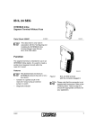
IB IL 24 PWR IN/M
Inline Power Terminal Without Fuse
According to the Requirements of
Germanischer Lloyd (GL)
Data Sheet 6840A
6 8 4 0 A 0 0 1
08/2002
Features
This data sheet is only valid in
association with the "Configuring and
Installing the INTERBUS Inline
Product Range" User Manual
IB IL SYS PRO UM E.
This terminal does not have a
protocol chip and is therefore not an
INTERBUS device.
–
Supply of the 24 V main voltage UM
–
Provision of the 24 V segment voltage US
Function
–
Provides protection for the station against
conducted surge voltages
The terminal is designed for use within an Inline
station.
–
Main and segment circuit protected by an
external fuse
–
Segment circuit can also be protected by a
segment terminal
–
Option to tap the protected 24 V voltage to
provide the bus terminal supply UBT
–
LED diagnostic indicator
The terminal supplies 24 V supply voltage to the
main circuit (UM) and thus provides the supply
voltage to the segment circuit (US).
The terminal has protective elements against
conducted surge voltages, which are specifically
designed to meet the requirements of
Germanischer Lloyd.
The terminal provides the option of tapping the
protected 24 V voltage (UM/US) to supply the bus
terminal supply UBT to a bus terminal (see
Figure 6 on page 7).
6840A
1
IB IL 24 PWR IN/M
Terminal Assignment
Terminal Assignment
Point
1.1, 2.1, Supply points for the main circuit UM
1.2, 2.2 (+24 V) and the segment circuit US
(+24 V)
U M
P W R
IN /M
Protected 24 V voltage tapped to
provide the bus terminal supply UBT
1
1.3, 2.3
These terminal points are connected
with each other and with the potential
jumper of the unprotected main
supply UM and the segment supply
US. The potential jumpers of the
unprotected main circuit UM and the
segment circuit US have a total
current carrying capacity of 8 A.
Ground contact (GND)
1.4, 2.4
The reference potential is directly
routed to the potential jumper and is,
at the same time, ground reference
for the main and segment voltage
and for the bus terminal supply UBT.
FE connection
2
1 .1
1
1
2 .1
1 .2
2
2
2 .2
1 .3
3
3
2 .3
1 .4
4
4
2 .4
6 8 4 0 A 0 0 2
Figure 1
IB IL 24 PWR IN/M
with appropriate connector
Please note that the connector is not
supplied as standard with the
terminal. Please refer to the Ordering
Data on page 11 to order the
appropriate connector for your
application.
Function Identification
Black
Local LED Diagnostic Indicator
Des. Color Meaning
UM
2
Green 24 V voltage present
(in the main circuit UM and in
the segment circuit US)
The contacts are directly connected
with the potential jumper and the FE
spring on the bottom of the housing.
The terminal is grounded when it is
snapped onto a grounded DIN rail.
Terminal points 1.1, 1.2, and 1.3 are
connected with a capacitor to FE.
Observe the current carrying
capacity
The maximum total current flowing
through the potential jumpers must
not exceed 8 A.
6840A
IB IL 24 PWR IN/M
Internal Circuit Diagram
Key:
IN T E R B U S
LED
Diode
U L
Protection against conducted
surge voltage
Capacitive connection to functional
earth ground (FE)
Other symbols are explained in the
IB IL SYS PRO UM E User
Manual.
+ 2 4
(U S
+ 2 4
(U M
V
)
V
)
6 8 4 0 A 0 0 3
Figure 2
6840A
Internal wiring of the terminal points
3
IB IL 24 PWR IN/M
Connection Example
Important Notes
Protect the 24 V supply with an
external fuse.
Only Inline terminals, which are approved by GL,
can be used within an Inline station that meets
the requirements of GL (see page 6).
The IB IL 24 PWR IN/M power terminal is used
to protect the Inline station against conducted
surge voltages according the requirements of
Germanischer Lloyd (GL approval).
U M
P W R
1
U
Only lead the supply cables to your Inline station
via IB IL 24 PWR IN/M power terminals to
ensure optimum protection of the Inline station
against conducted surge voltages (see Figure 6
on page 7).
IN /M
2
1
1
2
2
3
3
4
4
U
B T
M
6 8 4 0 A 0 0 4
Figure 3
Ground each IB IL 24 PWR IN/M power terminal
in the Inline station using the FE terminal point
(1.4 or 2.4). Contrary to information given in the
IB IL SYS PRO UM E User Manual, the station
is only grounded using all power terminals and
not using the bus terminal (see Figure 4).
Please note that the electrical isolation between
functional earth ground and the I/O is 175 V AC
when using the IB IL 24 PWR IN/M terminal
within an Inline station.
Typical connection of the supply
voltage UM and tapping of the bus
terminal supply UBT
The segment voltage US is provided
automatically.
To ensure maximum current carrying
capacity, use a power connector to
connect the cables (see page 11).
In these connectors, the adjacent
terminal points 1.2 and 2.2, and
1.3 and 2.3 are jumpered internally.
4
6840A
IB IL 24 PWR IN/M
2
1
3
2
3
3
3
4
3
3
O U T
U L
U M
B A
6
IN
5
D
1
D
1
2
R D
D
1
2
U M
D
1
2
D
1
2
D
1
2
2
6
R C
L D
P W R
B K -L K
R E M O T E
IN /M
P W R
IN /M
IN
1
1
2
2
1
2
1
2
1
2
1
2
1
2
1
2
1
2
F O 1
1
1 1
1 1
1 1
1 1
1 1
1 1
1 1
1 1
1
2
2 2
2 2
2 2
2 2
2 2
2 2
2 2
2 2
2
3
3 3
3 3
3 3
3 3
3 3
3 3
3 3
3 3
3
4
4 4
4 4
4 4
4 4
4 4
4 4
4 4
4 4
4
F O 2
R E M O T E
O U T
O U T
IN
6 8 4 0 A 0 0 8
Figure 4
Grounding an Inline station according to GL approval
Key:
Protective earth ground (PE)
No.
Function
Example
1
Bus terminal
IBS IL 24 BK-LK
2
Power terminal
IB IL 24 PWR IN/M
3
Terminals with GL approval according to the
application
See "GL Approved Inline Terminals" on
page 6 for approved terminals
4
End plate as end of the Inline station
Supplied with the bus terminal
5
Grounding terminal blocks (Universal ground
terminal block)
USLKG ... according to the configuration
(see CLIPLINE catalog from
Phoenix Contact).
6
End clamp
CLIPFIX 35
6840A
5
IB IL 24 PWR IN/M
GL Approved Inline Terminals
Only Inline terminals, which are approved by GL, can be used within an Inline station that meets the
requirements of GL.
Order No.
Order Designation
Hardware Revision
(or Later)
Firmware Revision
(or Later)
27 26 19 1
IBS IL 24 BK-LK
04
002
27 26 20 1
IB IL 24 DI 2
05
–
28 61 22 1
IB IL 24 DI 2-PAC
05
–
27 26 25 6
IB IL 24 DO 4
05
–
28 61 27 6
IB IL 24 DO 4-PAC
05
–
27 27 74 7
IB IL 24 SEG/F
03
–
28 61 37 3
IB IL 24 SEG/F-PAC
03
–
This list is continuously being extended. More information on new approved terminals can
be found on the Internet.
The hardware revision is imprinted on the side of the housing of every terminal.
For terminals with firmware, the firmware revision is also imprinted on the side of the
terminal housing.
The GL mark is imprinted on terminals that have been approved according to the
requirements of Germanischer Lloyd.
1
IL 2 4 D O 4
O rd e r-N o .: 2 7 2 6 2 5 6
M o d u le - ID : X X
2
Key:
1
3
IB
H W /S W
0 5 /-
Hardware revision
2
Firmware revision
3
GL mark
IN T E R B U S
6 8 4 0 A 0 0 9
Figure 5
6
Imprinting on an Inline terminal
6840A
IB IL 24 PWR IN/M
Installation Examples
IB IL 2 4
P W R IN /M
O U T
IB IL 2 4
S E G /F
IB IL 2 4
P W R IN /M
B U S
O P C
U
L +
U
A N A
L -
U
IN
R E M O T E
IN
7 .5 V
B U S
U
U
U
L +
A N A
L -
2 4 V
F O 1
U
F O 2
R E M O T E
IB IL 2 4
S E G /F
U
O U T
S
U
M
U
M
O U T
U
U
S
U
S
S
U
M
M
IN
U
B T
6 8 4 0 A 0 0 6
6 8 4 0 A 0 0 5
U
Figure 6
U
M
IB IL 24 PWR IN/M after a bus
terminal
Figure 7
M 1
IB IL 24 PWR IN/M to create a new
main circuit
The main voltage UM is supplied to the
IB IL 24 PWR IN/M terminal in the Inline station.
The segment voltage US is provided
automatically. The bus terminal supply UBT is
tapped from the protected 24 V voltage.
The main voltage UM is reintroduced to the
IB IL 24 PWR IN/M terminal. This opens an
electrically isolated main circuit within the Inline
station. The segment voltage US is provided
automatically.
Another segment is opened using a segment
terminal (given here as an example; a segment
terminal with fuse).
Another segment is opened using a segment
terminal (given here as an example; a segment
terminal with fuse).
In this example, there is no electrical isolation
between the logic (UL generated from UBT) and
I/O (UM/US).
In this example, there is electrical isolation
between the logic (UL generated from UBT) and
I/O (UM/US).
6840A
7
IB IL 24 PWR IN/M
Technical Data
General Data
Order Designation
IB IL 24 PWR IN/M
Order No.
28 61 02 7
Housing dimensions (width x height x depth)
12.2 mm x 120 mm x 71.5 mm
(0.480 x 4.724 x 2.815 in.)
Weight
50 g (without connectors)
Permissible temperature (operation)
-25°C to +55°C (-13°F to +131°F)
Permissible temperature (storage/transport)
-25°C to +85°C (-13°F to +185°F)
Permissible humidity (operation)
75% on average, 85% occasionally
In the range from -25°C to +55°C (-13°F to +131°F) appropriate measures against
increased humidity (> 85%) must be taken.
Permissible humidity (storage/transport)
75% on average, 85% occasionally
For a short period, slight condensation may appear on the outside of the housing if, for
example, the terminal is brought into a closed room from a vehicle.
Permissible air pressure (operation)
80 kPa to 106 kPa
(up to 2000 m [6562 ft.] above sea level)
Permissible air pressure (storage/transport)
70 kPa to 106 kPa
(up to 3000 m [9843 ft.] above sea level)
Degree of protection
IP 20 according to IEC 60529
Class of protection
Class 3 according to VDE 0106, IEC 60536
24 V I/O Supply (Main Circuit UM)
Connection
+24 V
Ground (GND)
Terminal points 1.1, 2.1, 1.2, and 2.2
Terminal points 1.3 and 2.3
Rated value
24 V DC
Tolerance
-15%/+20%
AC component
5%
8
6840A
IB IL 24 PWR IN/M
24 V I/O Supply (Main Circuit UM) (Continued)
Permissible range
19.2 V to 30 V
Permissible current
8 A, maximum
Demands on the voltage supply
The power terminal must be supplied from a new
power supply unit to provide electrical isolation.
Protect the 24 V power supply with an external
fuse.
The power supply unit must be able
to supply 4 times (400%) the
nominal current of the external fuse.
Safety Measures
Overload/short circuit in segment circuit
No
Surge voltage
Yes;
suppressor diode for voltage limitation between
terminal points 1.2 and 1.3
varistors for voltage limitation between
terminal points 1.2 and 1.4 and terminal points
1.3 and 1.4
Polarity reversal
Yes; diode connected in parallel as protection
against polarity reversal
The power supply unit must be able
to supply 4 times (400%) the
nominal current of the external fuse.
6840A
9
IB IL 24 PWR IN/M
Electrical Isolation/Isolation of the Voltage Areas
To provide electrical isolation between the logic level and the I/O area, it is necessary
to supply these areas via two power terminals from separate power supply units. Interconnection of the 24 V power supplies is not permitted. Please pay attention to
GND/PE connections on the power supply units (see also user manual).
Common Potentials
The 24 V main voltage supply, 24 V segment voltage, and GND have the same potential. FE is a
separate potential area.
Separate Potentials in the System Consisting of Bus Terminal/Power Terminal and I/O
Terminal
- Test Distance
- Test Voltage
5 V supply incoming remote bus/7.5 V supply (bus logic)
500 V AC, 50 Hz, 1 min.
5 V supply outgoing remote bus/7.5 V supply (bus logic)
500 V AC, 50 Hz, 1 min.
7.5 V supply (bus logic)/24 V supply (I/O)*
500 V AC, 50 Hz, 1 min.
24 V supply (I/O)/functional earth ground
175 V AC, 50 Hz, 1 min.**
*
Only applies if the communications power (supplied in the bus terminal from UBT) and I/O
voltage (UM, US) are supplied separately.
** Test voltage reduced due to voltage limiting elements.
Approvals
CE
Yes
UL/CUL
Applied for
GL Category A, B, C, D, EMC2
Applied for
Error Messages to the Higher-Level Control or Computer System
None
10
6840A
IB IL 24 PWR IN/M
Ordering Data
Description
Order Designation
Order No.
Power terminal without fuse according to the
requirements of Germanischer Lloyd (GL)
IB IL 24 PWR IN/M
28 61 02 7
You need one connector for the power supply of the terminal.
Connector for power supply
(black, w/o color print)
pack of 10
IB IL SCN-PWR IN
27 27 46 2
Connector for power supply
(black, with color print)
pack of 10
IB IL SCN-PWR IN-CP
27 27 63 7
"Configuring and Installing the INTERBUS Inline
Product Range" User Manual
IB IL SYS PRO UM E
27 43 04 8
Documentation is available to download free of charge at www.phoenixcontact.com.
6840A
11
© Phoenix Contact 08/2002 Technical modifications reserved TNR90 13 91 1
IB IL 24 PWR IN/M
Phoenix Contact GmbH & Co. KG
Flachsmarktstr. 8
32825 Blomberg
Germany
+49 - 52 35 - 30 0
+49 - 52 35 - 34 12 00
www.phoenixcontact.com
Worldwide Locations:
www.phoenixcontact.com/salesnetwork
12
6840A