1
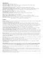
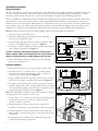
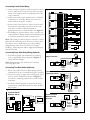
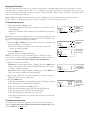
R
TM
TM
I r r i g a t i o n
C o n t r o l l e r
Installation Instructions – User Guide
AM
P1
3
Su Mo Tu We Th Fr Sa Su Mo Tu We Th Fr Sa
AUTO
MANUAL
OFF
RAIN DELAY
+
SET TIME & DATE
On
WATERING
DAYS
Esc
GLOBAL
ADJUST
PROGRAM
ADJUST
RUN TIMES
Next
–
Off
TEST
ASSIGN
PUMP / MV
TM
Table of Contents
Specifications .............................................................................................................................................1
Features.......................................................................................................................................................1
Controller Components..........................................................................................................................2–3
Installation Instructions .........................................................................................................................4–7
❏ Battery Installation.................................................................................................................................4
❏ Cabinet Installation................................................................................................................................4
❏ Connecting Control Valves....................................................................................................................5
❏ Connecting Pump Start Relay (Optional) ..............................................................................................5
❏ Connecting Toro Rain Switch (Optional) ...............................................................................................5
❏ ProgramLink™ (Slaved Controller Installation – Optional) .....................................................................6
❏ Selecting Control Options......................................................................................................................7
❏ Connecting Power and Equipment Ground Wires .................................................................................7
Set Clock and Calendar ..............................................................................................................................8
Running a Test Cycle..................................................................................................................................9
About the Controller Memory...................................................................................................................10
Clearing the Controller Memory...............................................................................................................10
About Programming the Controller .........................................................................................................11
Program Planning Record........................................................................................................................11
Helpful Programming Reminders ............................................................................................................11
Step A – Set Watering Day Schedule.................................................................................................12–13
❏ Calendar Schedule..............................................................................................................................12
❏ Interval Schedule ................................................................................................................................13
❏ Odd Days, Even Days or Off Mode......................................................................................................13
Step B – Set Program Start Time(s) .........................................................................................................14
Step C – Set Station Run Time .................................................................................................................15
Assign Pump/Master Valve Operation ....................................................................................................16
Watering Operation Controls ...................................................................................................................17
❏ To Pause Watering..............................................................................................................................17
❏ To Resume Watering (When Paused).................................................................................................17
❏ To Cancel Watering ............................................................................................................................17
❏ To Advance Through Watering Program(s).........................................................................................17
❏ To Modify Station Run Time ................................................................................................................17
Manual Control Operations ................................................................................................................18–19
❏ To Operate Selected Station(s) ...........................................................................................................18
❏ To Operate Selected Program(s) ........................................................................................................19
❏ To Operate All Programs.....................................................................................................................19
Season Adjust ...........................................................................................................................................20
❏ Program Adjust ...................................................................................................................................20
❏ Global Adjust.......................................................................................................................................20
Off and Rain Delay Modes ........................................................................................................................21
Station Control Modules...........................................................................................................................22
❏ Installing A Control Module..................................................................................................................22
❏ Removing A Control Module................................................................................................................22
Program Planning Charts...................................................................................................................23–24
Troubleshooting .......................................................................................................................................25
Quick Reference .........................................................................................................................Back Cover
Specifications
Transformer Type: Internally mounted.
Transformer Input: 120 VAC, 60 Hz, 60 Watts (max.) or 220/240 VAC, 50 Hz, 70 Watts (max.)
Transformer Output: 24 VAC, 50/60 Hz, 1.7 Amps
Station Output (maximum load) : 0.5 Amp @ 24 VAC 50/60 Hz (holding) @ 140° F (60° C)
Pump/Master Valve Output (maximum load): 0.35 Amp @ 24 VAC 50/60 Hz (holding) @ 140° F (60° C)
Maximum Combined Output: (2 Stations plus Pump/MV), 1.35 Amps @ 24 VAC @ 140° F (60° C)
Operating Temperature Range: 14° F – 140° F (-10° C – 60° C)
Circuit Breaker: 2.0 Amp, press to reset – protects 24 VAC Output
Secondary Surge Protection: Normally Open relay contact, one per output terminal
Fuse: 250 Volt 0.5 Amp, fast blow – protects AC Return
Battery Type and Back-Up Duration: 9-Volt Alkaline – 72 hours or 9-Volt NiCd – 10 Hours
Cabinet: Wall mount, weather resistant, 14-7⁄8" H x 11-1⁄4" W x 3-3⁄4" D (37.8 cm H x 28.6 cm W x 9.5 cm D)
Wiring Access Holes: Power/Ground Wiring - 7⁄8" (22 mm) for 1⁄2" conduit adapter
Control Wiring - 1-3⁄8" (35 mm) for 1" conduit adapter
Features
Modular Design: Plug-in control modules for station and pump/master valve output. 4-station control modules
provide convenient upgrade to 12 or 16 stations.
4 Independent Watering Programs (P1 – P4): Provide the scheduling flexibility required for the most
demanding landscape designs. Program features include: Watering days selectable by 14-day calendar, 1 to 14
day Interval or Odd/Even numbered days. Up to 6 program start times per day with up to 3 three repeat cycles
per start. Station run time duration from 0 (Off) to 120 minutes in 1-minute increments or 2 to 12 hours in
5-minute increments. Option provided for simultaneous operation of any two programs.
Self-Prompting, Multi-Lingual Display: Large, easy-to-read liquid crystal display with descriptive prompts
and icons. Word prompts are language-selectable in English, Spanish, French, Italian and German.
Vandal and Weather-Resistant Cabinet: High-impact plastic construction with locking, insulated cover. Cabinet design features hinged control panel for easy access to internal components, knock-out wiring access plugs
on base and back panels and isolated AC wiring compartment with safe, convenient terminal strip connection.
Battery Back-Up: Accepts 9-Volt Alkaline or NiCd battery to maintain real-time clock/calendar and operating
information during power interruptions. Enables controller to be fully programmed prior to connecting AC
power. Switch-controlled battery charging circuit maintains NiCd battery at peak charge. Displayed battery icon
signals low voltage condition.
Test Cycle: Provides 1 to 15 minute operation on each station for one cycle. Perfect for checking a new installation or whenever a short, temporary watering cycle is needed.
Rain Switch Ready: Built-in sensor port with manual override switch for the connection and control of a Toro
Rain Switch (model 850-74) or other normally-open rain sensing devices.
Pump/Master Valve Assignment: Enables pump or master valve operation to be assigned On or Off per
station as required.
Season Adjust: Automatically scales the programmed run time of each station down or up in 1% increments
from 10% to 250% of set value to easily compensate for seasonal watering demand. Program Adjust modifies
run time of all stations within a program; Global Adjust modifies run time of all stations in all programs.
Rain Delay: Suspends watering operation as needed from 1 to 7 days. Display shows days remaining until
watering resumes.
ProgramLink Operation: Enables two XF - 416 XF controllers to be linked together electronically for the
sequential operation of watering programs from one controller to the other. Provides synchronized operation of
up to 32 stations (16 stations per controller).
Manual Control: Enables manual operation of selected stations, selected programs or all programs as needed
to supplement the automatic watering schedule.
1
Controller Components
A
1
P1
B
C
D
P1 P2 P3 P4
PM
E
AM
PM
7
F
Su Mo Tu We Th Fr Sa Su Mo Tu We Th Fr Sa
AUTO
+
SET TIME & DATE
MANUAL
OFF
RAIN DELAY
START TIMES
PROGRAM
ADJUST
RUN TIMES
Esc
1 2 3 4 5 6 7 8 9 10 11 12 13 14 15 16
2
On
WATERING
DAYS
GLOBAL
ADJUST
Next
–
Off
H
I
ASSIGN
PUMP / MV
TEST
3
TM
4
5
19
6
18
7
17
8
16
9
15
10
11
14
13
2
12
G
Controller Components
1 - LCD Display
A - Program number indicators.
B - Display prompts for various programming and
operating functions.
C - Display prompts and time indicators for various programming and operating functions.
D - Watering On or watering interrupted (when
flashing).
E - Watering operations canceled.
F - AC power disconnected (controller operating
on battery back-up).
G - Low battery voltage - replace battery.
H - Percentage indicator for season adjust value.
I - Number indicators for days, stations and program start times.
2 - Control Buttons
+ /On - Increases time display, steps forward
through program elements, selects On, watering
days and active stations.
–/Off - Decreases time display, steps backward
through program elements, selects Off, omits
watering days and stations.
Next - Selects next portion of program information. Resumes a paused watering operation.
Esc (Escape) - Press once to return to beginning
of programming procedure or pause a watering
operation. Press twice to exit a programming
procedure or cancel a watering operation.
3 - Control Dial
Auto - Normal dial position for automatic and
manual watering operations.
Time & Day - Accesses clock and calendar mode
to change or review current settings.
Watering Days - Accesses programming mode to
set or review program watering day schedule.
Start Times - Accesses programming mode to
set or review program start times.
Run Times - Accesses programming mode to set
or review station run times.
Assign Pump/MV - Accesses programming mode
to assign pump/master valve operation On or
Off for each station.
Test - Accesses Test program for quick check of
system operation.
Program Adjust - Accesses programming mode
to change run time of all stations in a program by
a percentage value from 10% – 250%.
Global Adjust - Accesses programming mode to
change run time of all stations in all programs by
a percentage value from 10% – 250%.
Off / Rain Delay - Selects Off and Rain Delay
modes to suspend system operation.
Manual - Accesses manual operation modes.
4 - Circuit Breaker - Rated @ 2.0 Amps, protects
24 VAC output. Push to reset if tripped.
5 - Rain Switch Connection Terminals - For connection of Toro Rain Switch or other normally
open rain sensing device.
6 - Fuse - Rated 0.5 Amps, protects controller's electronic circuitry.
7 - Spare 0.5 Amp Fuse
8 - Station Output Control Module - Plug-in module
with connections for 4 station outputs.
9 - Expansion Slot - Enables installation of additional
4-station control module.
10 - Pump/Common Output Control Module - Plugin module with connections for pump/master
valve and two 24 VAC commons.
11 - Wiring Access Plugs - Knock-out plugs on base
and back panel for 1⁄2" and 1" conduit adapters.
12 - AC Power Terminal Strip - Enables easy, safe
connection of AC wiring for 120 VAC 60 Hz or
220/240 VAC 50 Hz power source.
13 - Transformer - 120 VAC 60 Hz or 220/240 VAC
50 Hz input, 24 VAC 50/60 Hz output.
14 - 9-Volt Battery - Alkaline or NiCd, supplies backup power to maintain real time clock operation
during an AC power interruption. Enables controller to be programmed prior to installation.
15 - Control Option Jumpers - Enables easy selection
of optional control features. See “Selecting Control
Options”, page 7 for details.
16 - Sensor On/Off Switch - Controls sensor input to
enable or disable Rain Switch operation.
17 - ProgramLink Control Cable Connection Port Connection port for slaved controller installation.
See “ProgramLink – Slaved Controller Installation”, page 6 for detailed information.
18 - Multi-Program Option Jumper - Enables simultaneous operation of two programs. See “Selecting
Control Options”, page 7 for details.
19 - Battery Switch- Two-position switch for Alkaline
or NiCd battery installation. NiCd position activates battery charging circuit.
3
Installation Instructions
Battery Installation
The XF - 416 utilizes a 9-Volt battery to maintain current time/date and controller operating information during an
AC power failure. The battery also enables the controller to be fully programmed prior to installation. To take
advantage of this feature, skip ahead to “Set Clock and Calendar” on page 8 after installing the battery.
Either an Alkaline or a NiCd battery can be installed. The Alkaline battery provided with the controller will last for
approximately 72 hours of continuous duty. A fully charged NiCd battery will last for approximately 10 hours of
continuous duty. Even though the NiCd battery has a shorter duty cycle, it is a better choice for areas with frequent
power failures, since it is continuously held at peak charge by the controller's charging circuit. If the battery is not
installed, or its voltage is below minimum requirements, the low battery voltage indicator will be displayed.
Note: The battery will not operate the station/pump outputs; AC power must be connected.
1. Unlock and open controller cover.
2. Carefully swing hinged control panel open, grasping it
from the lower right side edge.
3. Locate battery clip and attach it to battery terminals. Place
battery into holding bracket as shown in Figure 1.
4. Set battery switch to Alkaline or NiCd position according to
type of battery installed. See Figure 1.
Figure 1
Caution: The battery switch must be properly set for the type of
battery installed. Switch set in NiCd position can cause an Alkaline
battery to overheat and leak, possibly damaging the controller.
Battery
Alkaline Ni-cad
9-Volt
Alkaline
9V
5. Clock time display will begin flashing. To halt flashing,
press any control button.
Cabinet Installation
Figure 2
1. Remove lower access cover secured with a single screw.
2. Carefully remove 7⁄8" (22 mm) and 1-3⁄8" (35 mm) wiring
access knock-out plugs from base or back of cabinet as
required. See items A and B in Figure 2.
3. Using a small screwdriver or punch, remove lower mounting screw hole plugs as required. See item C in Figure 2.
4. To expose top mounting hole, remove top station control
module. Slide locking tab to the left. Slide module carefully
C
to the right; disengaging it from PC board receptacles and
slotted openings in guide rails. See Figure 3.
Note: If installing the controller on drywall or masonry, install
the appropriate screw anchors as necessary.
Figure 3
5. Using a #10 x 1-1⁄2" (38 mm) wood screw (provided) install
top mounting screw into wall at eye level leaving 1⁄2"
(12 mm) of screw exposed.
6. Hang controller on screw using keyhole shaped slot.
7. Install lower mounting screws and tighten all screws securely.
8. Carefully position control module into slotted guide rails.
Slide module to the left; plugging it securely into PC board
receptacles.
9. Install optional 1⁄2" conduit for AC /Ground wiring and 1"
conduit for field wiring at this time.
4
B
C
C
A
Locking
Tab
Top
Mounting
Screw
Connecting Control Valve Wiring
1. Using waterproof splices, attach a separate control Figure 4
wire to either lead of each control valve solenoid.
Attach one common wire to remaining lead of all
valve solenoids.
2. Label control wires and common wire to facilitate
connection to controller. Route wires into controller cabinet through 1" conduit.
3. Secure valve control wires to station control modules in desired operating sequence. Secure common wire to either common terminal of
pump/master valve control module. See Figure 4.
4. If installing an optional master valve, connect one
solenoid lead to Pump terminal and remaining lead
to Common terminal or Valve Common wire.
1
2
3
4
5
6
7
8
9
10
11
12
13
14
Note: Valve load per station must not exceed 0.5 amps
@ 24 VAC. If connecting more than one control valve
per station, ensure total amperage load (including
pump/master valve) does not exceed 1.35 amps
(holding). Circuit breaker will be tripped if maximum
load is exceeded.
Connecting Pump Start Relay Wiring (Optional)
1. If automatic pump start installation is required,
refer to applicable wiring diagram in Figure 5
and install accordingly.
Note: Pump/master valve load must not exceed
0.35 amps @ 24 VAC.
15
PCC
16
Master Valve
Figure 5
Pump
Single Controller
Magnetic
Starter
COM
COM
PUMP
Relay
24 VAC
0.35 Amp
(max.)
Connecting Toro Rain Switch (Optional)
1. Route wire cable from Toro Rain Switch (model
number 850-74) into controller through 1" conduit.
2. Connect 18 gauge copper wire and 24 gauge silver
wire to sensor terminals as shown in Figure 6.
Cut off two remaining cable wires at end of cable
insulation.
3. Set Sensor Switch position as required. Position
switch On to enable Rain Switch or Off to disable
Rain Switch.
Sensor
Voltage
Source As
Required
COM
COM
PUMP
Relay
24 VAC
0.35 Amp
(max.)
Pump
Magnetic
Starter
COM
COM
PUMP
Pressure Switch
With Controller
Override
Relay
24 VAC
0.35 Amp
(max.)
Voltage
Source As
Required
Pump
Power
Source
Pressure Switch
Pump
Magnetic
Starter
On Off
9V
Pump
Power
Source
Two Controllers
(Slaved Operation)
Figure 6
Toro Rain Switch
Model No. 850-74
COM
COM
PUMP
COM
COM
PUMP
Relay
24 VAC
0.35 Amp
(max.)
Voltage
Source As
Required
Pump
Power
Source
5
ProgramLink™ – Slaved Controller Installation (Optional)
The ProgramLink feature enables two XF - 416 controllers to be slaved (linked) together electronically for the
sequential operation of watering programs synchronized from one controller to the other.
The controllers are connected via a cable assembly attached to the back of each control panel. The slaved controller is designated by the removal of control option Jumper #3. Once the jumper is removed, a programming
option is made available to the slaved controller which enables each watering program to be automatically started by the master controller as desired.
During operation, the master controller sends a start command to the slaved controller at the end of each watering program cycle. If programmed to do so, the slaved controller will automatically respond by starting the
watering cycle of the matching program number. For example: The slaved control option has been assigned
(On) for Program 1 of the slaved controller. As the last station in Program 1 of the master controller finishes
operation, Program 1 watering cycle of the slaved controller will start automatically.
It is important to note that a slaved controller has the option of operating independently as needed. The slaved
operating mode can be assigned On or Off for any program (P1 – P4) and additional start times can be assigned
to any program as required.
Installing Cable Assembly
1. Install controllers within close
Figure 7
proximity of one another.
2. Route cable assembly between controllers and connect to receptacles
provided on the control panel PCB.
Dress cable through retaining clips
located beneath large ribbon conductor cable.
See Figures 7 and 8.
Note: Cable plugs are keyed to fit receptacles in one direction only. Do not
force plugs into receptacles.
3. Position control option Jumper #3
to determine master and slaved
controller as shown in Figure 8.
Note: The procedure for assigning
slaved operation of program(s) is
provided in Step B - Set Program Start
Figure 8
Time(s) on page 14.
Retaining Clip
9V
7
6
5
4
3
2
1
Master Controller
6
9V
7
6
5
4
3
2
1
Slaved Controller
Selecting Control Options
Removable jumpers are provided which enable various control options to
be easily selected. The jumpers are located on the back of the control
panel as indicated in Figure 9. The change caused by the removal or
installation of a jumper will become effective immediately. Disconnecting
the battery or removing power to the controller is not required. The control options provided are as follows:
Jumper 1 - Installed - Selects 12-hour (a.m./p.m.) clock mode.
Removed - Selects 24-hour clock mode.
Jumper 2 - Installed - Provides a 15 second delay after pump
start and between station output sequence.
Removed - 15 second delay Off.
Jumper 3 - Installed - Designates “Master” controller.
Removed - Designates “Slaved” controller.
Note: Positions 4 – 7 are provided for the selection of alternate language
formats for some of the display prompts, i.e., calendar month. If a jumper is
not installed in one of these positions, English prompts are selected. One
jumper is provided for the selection of an alternate language as follows:
Position 4 - Jumper installed selects Spanish display prompts.
Figure 9
Multi-Program
Jumper
7
9V
6
5
4
3
2
1
Note: After removal, install
jumper(s) on one pin for storage.
Position 5 - Jumper installed selects French display prompts.
Position 6 - Jumper installed selects German display prompts.
Position 7 - Jumper installed selects Italian display prompts.
Multi-Program Jumper - Installed - Allows only one watering program to operate at a time.
Removed - Enables any two watering programs to operate simultaneously.
Connecting Power and Equipment Ground Wires
WARNING
ALL ELECTRICAL CONNECTIONS MUST BE MADE IN COMPLIANCE WITH ALL APPLICABLE ELECTRICAL CODES.
DISCONNECT POWER TO CONTROLLER AT SOURCE PRIOR TO MAKING ANY WIRE CONNECTIONS. FAILURE TO
COMPLY MAY RESULT IN SERIOUS INJURY AND /OR EQUIPMENT DAMAGE.
1. Route insulated three-core power/ground cable
120 VAC
from 120 VAC 60 Hz or 220/240 VAC 50 Hz power Figure 10
source into transformer compartment through 1⁄2"
4 3 2 1 EARTH
conduit.
2. For 120 VAC input, refer to Figure 10 and connect wires to terminals as follows:
• EARTH - Equipment ground (bonded to ground)
• Terminal 1 - Neutral
• Terminal 2 - 120 VAC 60 Hz Line
For 220/240 VAC input, refer to Figure 11 and
connect wires to terminals as follows:
• EARTH - Equipment ground (bonded to ground)
• Terminal 1 – Neutral
• Terminals 2 and 3 - Install jumper wire (use appropriate wire size)
• Terminal 4 - 220/240 VAC 50 Hz Line
3. Install lower access cover.
4. Apply power to controller.
Figure 11
220/240 VAC
4 3 2 1
EARTH
7
Set Clock and Calendar
Synchronizing the controller's clock and calendar to the current time and date is an important first step in
preparing the controller for automatic operation. The actual starting times and days that automatic watering will
take place are based on the information entered during this procedure.
To set current time and date:
AM
1. Turn the Control Dial to the TIME & DATE position.
❑ The clock time display will begin flashing.
2. Press the +/On or –/Off button to increase or decrease the clock
display until the current time is shown.
Current clock
setting.
7
Press and hold either button for more than three seconds to
change the display rapidly.
❑ Observe for the correct a.m./p.m. reference. (Applies to 12-hour
clock mode only.)
3. Press the Next button.
❑ The calendar date will be displayed and the month will begin
flashing.
PM
❑
Current time set.
Example: 3:25 PM.
7
Advance to
calendar month.
display.
7
Current month set.
Example: March.
4. Press the +/On or –/Off button as needed to display the current
month.
3
Advance to
calendar day
display.
5. Press the Next button.
❑ The calendar day will begin flashing.
3
Current calendar
day set.
Example: March 6.
6. Press the +/On or –/Off button as needed to display the current
calendar day.
1
Advance to
calendar year
display.
7. Press the Next button.
❑ The calendar year will begin flashing.
1
Current year set.
Example: 1995.
8. Press the +/On or –/Off button as needed to display the current
calendar year.
2
9. Press the Next button.
❑ The current day number of the 14-day (two-week) cycle will
begin flashing.
Advance to
current day of
two-week cycle.
2
Su MoTu We Th Fr Sa Su Mo Tu We Th Fr Sa
10. Press the +/On or –/Off button as needed to place the current day
number within week 1 or week 2 of the two-week cycle.
11. Return the Control Dial to the AUTO position.
❑ The current time and day number will be displayed.
❑ The colon (:) in the clock time display will flash continuously
when displaying the time and day.
8
9
Su MoTu We Th Fr Sa Su Mo Tu We Th Fr Sa
Current day of
2-week cycle set.
Example: Monday
of week 2.
Running A Test Cycle
The Test Cycle feature enables you to quickly verify proper controller timing function and operation of each
watering station. A temporary run time of 1 – 15 minutes is assigned to all stations selected for the test. The test
cycle will operate each station in sequence for the selected run time. When the test concludes, the display will
return to the current time and day.
Note: Additional manual control features become available when the controller test watering cycle is in
progress. Refer to “Watering Operation Controls” on page 17 once watering has started.
To operate the test cycle:
1. Turn Control Dial to TEST position.
❏ TST will be displayed and station run time (1 – 15 minutes) will
begin flashing.
❏ All station numbers will be displayed and underlined (selected to
operate).
Note: If the station count displayed does not correspond with the number of station modules installed, refer to “Station Control Modules” on
page 22 to verify proper module installation.
2. Press the +/On or –/Off button as needed to increase or decrease the
station run time (1 – 15 minutes).
❏ Press and hold either button for more than three seconds to
change the display rapidly.
3. Press the Next button.
❏ Station number 1 will begin flashing.
Note: If you wish to test only selected stations, continue at step 4.
If you wish to test all stations, press the Next button again to start the
test cycle, then return the Control Dial to the AUTO position.
4. Select the station(s) as follows:
To select the station number which is flashing, press the +/On button.
❏ The station number will remain underlined and the next station
number will begin flashing.
To omit the station number which is flashing, press the –/Off button.
❏ The next station number will begin flashing.
5. Repeat step 4 until only the station numbers you wish to operate
during the Test Cycle are underlined.
6. Press the Next button.
❏ The first selected station in numerical sequence will begin watering.
❏ The “Watering On” symbol will be displayed.
7. Return the Control Dial to the AUTO position.
❏ TST and the remaining station run time will be displayed.
❏ The operating station number will begin flashing.
❏ All remaining stations will operate in sequence.
❏ The display will return to the current time and day when the test
cycle is finished.
1 2 3 4 5 6 7 8
Test Cycle mode
selected.
Example: 5 minutes station run
time set.
Example: Station
run time set to
1 minute.
1 2 3 4 5 6 7 8
Advance to station select. Station 1 flashing.
1 2 3 4 5 6 7 8
1 2 3 4 5 6 7 8
1 2 3 4 5
Example: Stations
1 – 5 selected to
operate. Stations
6 – 8 omitted from
test.
Control Dial in
Auto position.
Station 1 On, 59
seconds run time
remaining.
To terminate the test cycle:
To terminate the Test Cycle operation and return to the time and day
display, ensure the Control Dial is turned to the AUTO position, then
press the Esc button two times.
9
About The Controller Memory…
The XF - 416 can be programmed when powered by either a 9-Volt battery or AC line voltage. As the watering
program information, i.e., watering days, cycle start times and station run times, is selected, it is being stored in
a computer memory chip. The chip will retain the program information indefinitely when sustained by a power
source or for a minimum of one year without power. If the controller has a fully charged battery installed and an
AC power interruption occurs, the controller will continue to keep current time and operate as programmed,
however no watering will take place, as 24 VAC is required to open the control valves. If the battery is discharged or is not installed and an AC power interruption occurs, all controller operation will cease, however, the
watering program information will remain intact. When power is restored, the clock time and date will default
to 12:00 a.m., January 01, 1994. Automatic operation will occur as programmed but will not be synchronized
with real time. To restore operation, simply install a new battery, then reset the clock and calendar to current
time and date.
When shipped from the factory, the watering program memory is clear. If the controller has been previously
programmed and you wish to erase or clear the memory, refer to “Clearing the Controller Memory” below for
this procedure.
Clearing The Controller Memory
NOTICE ! The following procedure will erase all user-defined program information (except current time and date).
Please note that it is not possible to retrieve this data once it has been erased!
Procedure:
1. Turn the Control Dial to the OFF / RAIN DELAY position.
Off mode
selected.
❏ OFF will be displayed and the “no watering” symbol will begin
flashing.
2. Press and hold the +/On and –/Off buttons until CLR (clear) is
displayed.
3. Return the Control Dial to the AUTO position.
10
Controller
Memory cleared.
About Programming The Controller…
The XF - 416 provides 4 fully independent automatic watering programs. In order for a program to operate automatically, the following information must first be selected:
Watering Days – The watering day schedule determines which day(s) an automatic program will operate. Each
program can utilize one of the following types of schedules:
Calendar schedule for watering on specific days of a two-week (14-day) cycle.
Interval schedule for watering days based on frequency ranging from 1 (every day) to 14 (every 14th day).
Odd day schedule for watering on all odd numbered calendar days.
Even day schedule for watering on all even numbered calendar days.
Off mode to prevent the automatic operation of any program.
Cycle Start Times – This procedure determines when the program watering cycle will start on a scheduled
watering day. Up to six different start times per day can be set for each program. When a program watering
cycle starts, each station with an assigned run time for that program will operate one at a time in numerical
sequence for its set run time duration.
Station Run Times – This procedure establishes the duration or length of time each station will operate during a
watering program cycle. Each station can have a different run time assigned in each program. Run time can be
selected from 0 (OFF) to 120 minutes in 1-minute increments or from 2 to 12 hours in 5-minute increments.
These are the essential three programming steps which must be accomplished for automatic operation. All other
control features are provided for user convenience and to further enhance the effectiveness of the irrigation system in maintaining a healthy landscape.
Program Planning Chart
To help organize your watering program information and assist you in the step-by-step programming procedures,
we recommend that you take a few minutes to fill in the watering schedule information for each program on the
watering program planning charts provided on pages 23 and 24. (See example in Figure 12 below.) You will be
able to see at a glance a complete overview of your automatic watering schedules in addition to having a handy
reference guide during the programming procedures.
Figure 12
Program Number - P
Watering Days
Su Mo Tu We Th Fr Sa Su Mo Tu We Th Fr Sa
Calendar
Interval 1 2 3 4 5 6 7 8 9 10 11 12 13 14
Program Cycle Start Times Slaved Operation Mode - Off
1
:
a.m.
p.m. Off
Station Run Time
hrs.
min.
Sta. 1
hrs.
min.
Sta. 2
hrs.
min.
Sta. 3
hrs.
min.
Sta. 4
2
:
a.m.
p.m. Off
Cycle Repeat Off
Off
Off
Off
Sta. 5
Sta. 6
Sta. 7
Sta. 8
3
:
a.m.
p.m. Off
1 (no repeats)
hrs.
min. Off
hrs.
min. Off
hrs.
min. Off
hrs.
min. Off
Odd Days
Even Days
Off
On
4
:
2 (1 repeat)
Sta. 9
Sta. 10
Sta. 11
Sta. 12
a.m.
p.m. Off
5
:
3 (2 repeats)
hrs.
min. Off
hrs.
min. Off
hrs.
min. Off
hrs.
min. Off
a.m.
p.m. Off
6
:
4 (3 repeats)
Sta. 13 hrs.
Sta. 14 hrs.
Sta. 15
Sta. 16
hrs.
hrs.
a.m.
p.m. Off
min. Off
min. Off
min. Off
min. Off
Helpful Programming Reminders
When performing any programming procedures, please keep in mind the following operational characteristics:
•Only the flashing portion of the display can be changed.
•If you make a mistake during a procedure, simply press the Esc (escape) button; then repeat the procedure steps as needed to change the display.
•All programming information is automatically stored in the controller memory as it is being selected or changed. Therefore, a formal “Enter” button is not required.
•If no control button is pressed within 15 minutes after starting a programming procedure, the controller will return to the Auto mode and the time and day will be displayed. To resume programming,
return the control dial to the Auto position, then start the programming procedure over at step 1.
11
Step A - Set Watering Day Schedule
The watering day schedule determines which day(s) an automatic program will operate. Each program can utilize one of the following watering day scheduling modes:
Calendar schedule, which enables watering days to be selected by specific days (Sunday through Saturday) of a
two-week (14 day) cycle.
Interval schedule, which establishes watering days based on how often watering must occur, without regard to
actual calendar days. The available interval schedules range from 1 (every day) to 14 (every 14th day).
Odd day mode for watering on all odd numbered calendar days.
Even day mode for watering on all even numbered calendar days.
Off mode to prevent the automatic operation of any program as required. Placing a program in the OFF mode
removes all active watering days from the program but does not affect other portions of the program operating
data which may be entered, such as station run time or start times. This effectively prevents automatic operation
of the program but enables it to be operated manually as needed. The program will remain in the OFF mode
until a Calendar, Interval, Odd or Even watering day schedule is selected. Any unused programs should be
placed in the OFF mode.
Use one of the following procedures to set a watering day schedule:
Calendar Schedule
1. Turn the Control Dial to WATERING DAYS position.
2. Program P1 indicator will begin flashing. To select program P2, P3,
or P4, press the + /On or – /Off button until the desired program
indicator begins flashing.
❑ The current watering day mode (CAL, INT, ODD, EVN or OFF)
for the program selected will be displayed.
3. Press the Next button.
❑ The watering day mode will begin flashing.
4. Press the + /On or – /Off button (if needed) to select CAL (Calendar).
❑
Program 1
selected. This
program is currently set to Off
mode.
P1
Advance to watering day mode.
P1
Select Calendar
watering day
mode.
Day numbers 1 – 14 are displayed and the current watering days
are underlined.
5. Press the Next button.
❑ Day number 1 will begin flashing.
❑ If day number 1 is set to water, the number is underlined and On
is displayed.
❑ If day number 1 is not set to water, the number is not underlined
and Off is displayed.
6. Set the watering day schedule as follows:
For watering on the day number (flashing), press the +/On button.
❑ The next day number will begin flashing. On or Off is displayed
for that day number.
For no watering on the day number (flashing), press the –/Off
button.
❑ The next day number will begin flashing. On or Off is displayed
for that day number.
7. Repeat step 6 to set all 14 days as needed.
8. Return the Control Dial to the AUTO position.
12
P1
1 2 3 4 5 6 7 8 9 10 11 12 13 14
P1
1 2 3 4 5 6 7 8 9 10 11 12 13 14
Current watering
day schedule for
this program –
water everyday.
Su MoTu We Th Fr Sa Su Mo Tu We Th Fr Sa
P1
1 2 3 4 5 6 7 8 9 10 11 12 13 14
Su MoTu We Th Fr Sa Su Mo Tu We Th Fr Sa
Watering day
schedule set.
Example: Watering set for Monday and Thursday
of both weeks.
Interval Schedule
1. Turn the Control Dial to the WATERING DAYS position.
2. Program P1 indicator will begin flashing. To select program P2, P3,
or P4, press the + /On or – /Off button until the desired program
indicator begins flashing.
3. Press the Next button.
❏ The current watering day mode (CAL, INT, ODD, EVN or OFF)
will begin flashing.
4. Press the +/On or –/Off button as needed until INT (Interval mode) is
flashing.
P1
Program 1
selected. Current
watering day
mode is Off.
P1
Advance to watering day mode.
P1
Select Interval
watering day
mode.
1
5. Press the Next button.
❏ The current interval number (1 – 14) will begin flashing and all
numbers preceding the interval number are displayed.
❏ The interval starting day is underlined.
P1
1
6. Press the +/On or –/Off button as needed until the desired interval
number is displayed and flashing.
1 = every day 2 = every other day 3 = every third day, etc.
P1
7. Press the Next button.
❏ The number underline will begin flashing.
P1
Current Interval
schedule for this
program.
Example: Water
everyday (1).
Interval selected
Example: Water
every third day (3).
1 2 3
Advance to
Interval start day.
1 2 3
8. Press the +/On or –/Off button as needed to place the underline
beneath the initial starting day (watering day) of the interval.
1 = today 2 = tomorrow 3 = two days from today, etc.
9. Return the Control Dial to the AUTO position.
P1
1 2 3
Interval start day
selected.
Example: Start
Interval tomorrow
(2).
Odd Days, Even Days, Or Off Mode
1. Turn the Control Dial to the WATERING DAYS position.
2. Program P1 indicator will begin flashing. To select program P2, P3,
or P4, press the + /On or – /Off button until the desired program
indicator begins flashing.
P2
1 2 3
3. Press the Next button.
❏ The current watering day mode (CAL, INT, ODD, EVN or OFF)
will begin flashing.
P2
4. Press the +/On or –/Off button as needed until the desired mode
(ODD, EVN or OFF) is flashing.
5. Return the Control Dial to the AUTO position.
P2
Program 2
selected. Current
watering day
mode is 3-day
interval.
Advance to
watering day
mode.
1 2 3
New watering day
mode selected.
Example: Even
number watering
days selected.
13
Step B - Set Program Start Time(s)
This procedure determines when the program watering cycle will start on a scheduled watering day. Up to six
different start times per day can be set for each program, however, only one start time is required to operate a
program automatically. When a program watering cycle starts, each station with an assigned run time for that
program will operate one at a time in numerical sequence for its run time duration.
Note (for optional Multi-Program operation): When setting program start time(s), remember that two programs
can operate simultaneously. If the irrigation system water supply cannot support multiple station operation, schedule start times which enable one program to complete its watering cycle before the next program cycle starts. Also
note that any program which starts while two programs are in operation will be delayed until one of the operating
programs has completed its watering cycle.
Set program start time(s) as follows:
1. Turn the Control Dial to the START TIMES position.
2. Program P1 indicator will begin flashing. To select program P2, P3,
or P4, press the + /On or – /Off button until the desired program
indicator begins flashing.
❏ Start time numbers 1 – 6 will be displayed. The start time numbers
which currently have an assigned start time for this program are
underlined.
3. Press the Next button.
Note: If the ProgramLink option is being utilized (jumper #3
removed), SLV (slave) On or OFF will be displayed. If the ProgramLink option is not selected, this information will not be displayed.
Skip step 4 if ProgramLink is not being used at this time.
4. To operate this program in the Slaved mode, press the +/On button.
❏ On will be displayed.
If the Slaved operation mode is not desired for this program, press
the –/Off button.
❏ Off will be displayed.
5. Press the Next button.
❏ Start time number 1 will begin flashing.
6. Press the +/On or –/Off button (if needed) to select a different start
time number (2 – 6).
❏ The currently assigned start time or OFF will be displayed.
7. Press the Next button.
❏ The currently assigned start time or OFF will begin flashing.
Program 1
selected. No start
times currently set
for this program.
P1
1 2 3 4 5 6
Advance to
Slaved control
option. Example:
Slaved mode On
for program 1.
P1
1 2 3 4 5 6
Advance to select
start time number.
P1
1 2 3 4 5 6
Start time 1
selected.
Example: Start
time #1 currently
Off
P1
1
8. Press the +/On or –/Off button as needed to display the desired start
time or OFF.
❏ Press and hold either button for more than three seconds to
change the display rapidly.
❏ Observe for the correct a.m./p.m. reference. (Applies to 12-hour
clock mode only.)
❏ For all unused start times, select OFF located between 11:59 p.m.
and 12:00 a.m. (23:59 and 0:00).
9. Press the Next button.
❏ The next start time number in sequence will begin flashing
10. Repeat steps 6 – 9 to set additional program start times as needed.
11. Return the Control Dial to the AUTO position.
14
P1
AM
1
P1
1 2 3 4 5 6
Start time set.
Example: start
time #1 set for
2:00 AM.
Advance to select
next start time
number. Example:
start time #2
currently Off.
Step C - Set Station Run Time
This procedure determines the length of time each station will operate during a watering program cycle. The number of stations displayed (4, 8, 12 or 16) is automatically determined by the number of 4-station control modules
installed. Each station can have a different run time assigned in each program. Run time can be selected from
0 (OFF) to 120 minutes in 1-minute increments or from 2 to 12 hours in 5-minute increments.
A cycle repeat option is provided which enables each program watering cycle to operate up to 4 times per start
time. When cycle repeat is used, the controller automatically calculates a reduced run time for each station by
dividing the amount of run time for each station by the number of repeat cycles selected. In doing this, multiple
watering/soak applications can be scheduled without increasing the station run time and total program cycle time.
For example: Stations 1 – 4 each have 20 minutes run time assigned in program 1 and the program has been set to
cycle 2 times (1 cycle + 1 repeat cycle). When the program watering cycle starts, each station will operate in
sequence for 10 minutes. The program cycle will then immediately start over and run each station again for 10
minutes. (20 minutes ÷ 2 cycles = 10 minutes x 2 cycles.)
Set station run time as follows:
1. Turn the Control Dial to the RUN TIMES position.
2. Program P1 indicator will begin flashing. To select program P2, P3,
or P4, press the + /On or – /Off button until the desired program
indicator begins flashing.
❏ All station numbers are displayed. Stations which currently have
an assigned run time for the selected program are underlined.
3. Press the Next button.
❏ CYC (cycle repeat option) will be displayed.
❏ The number of cycles (1 – 4) selected for this program will begin
flashing.
4. Press the +/On or –/Off button (if needed) to select the number of
repeat cycles desired.
1 = 1 cycle (no repeat)
2 = 1 cycle + 1 repeat
3 = 1 cycle + 2 repeats
4 = 1 cycle + 3 repeats
5. Press the Next button.
❏ Station number 1 will begin flashing.
6. To select a different station number, press the +/On or –/Off button
until the desired station number is flashing.
❏ OFF or the currently assigned run time will be displayed.
7. Press the Next button.
❏ Only the station number selected will be displayed.
❏ OFF or the currently assigned run time will begin flashing.
8. Press the +/On or –/Off button as needed to display the desired run
time or OFF (located between 12:00 and 0:00).
❏ Press and hold either button for more than three seconds to
change the display rapidly.
❏ The display will change in 1-minute increments from 1 minute
to 2 hours, and 5-minute increments from 2 to 12 hours.
9. Press the Next button.
❏ The next station number in sequence will begin flashing.
10. Repeat steps 6 – 9 until all stations to be operational in this program
have an assigned run time.
11. Return the Control Dial to the AUTO position.
P1
1 2 3 4 5 6 7 8
P1
1 2 3 4 5 6 7 8
Program 1
selected. Example:
8 stations installed,
no assigned run
times in program 1.
Advance to Cycle
Repeat mode.
Current setting, 1
cycle - no repeats
for program 1.
Example:
program 1 set
for 1 repeat cycle.
P1
1 2 3 4 5 6 7 8
Advance to select
station 1.
P1
1 2 3 4 5 6 7 8
P1
1
Example; station
1 currently has no
run time assigned
in program 1.
Example; run time
for station 1 set
for 20 minutes.
P1
1
Advance to select
next station.
P1
1 2 3 4 5 6 7 8
Note: This completes the programming steps required to operate a program automatically.
Repeat programming procedures A, B and C for each program (P1 – P4) as needed.
15
Assign Pump / Master Valve Operation
This feature allows the pump/master valve (mv) output to be assigned On or Off as needed for each station. For
example, if a station is controlling drip or sub-surface irrigation with a water source which is not pump assisted,
pump operation can be automatically disabled when the station begins watering by selecting pump/mv Off.
By default, all stations are assigned with pump/mv On. To review and/or change the current station assignments, use the following procedure:
1. Turn the Control Dial to the ASSIGN PUMP/MV position.
❏ Program indicators P1 – P4 will be displayed.
❏ All station numbers will be displayed.
❏ Underlined station number indicates pump/mv is operational.
❏ Station number 1 will begin flashing. If the station is underlined,
On will be displayed; if not underlined, Off will be displayed.
2. Assign pump/mv On or Off for each station as follows:
To assign pump/mv On for the station number which is flashing,
press the +/On button.
❏ The station number is underlined and the next station number
will begin flashing.
To assign pump/mv Off for the station number which is flashing,
press the –/Off button.
❏ The underline will disappear and the next station will begin
flashing.
3. Repeat step 2 for all stations as needed.
4. Return the Control Dial to the AUTO position.
16
P1 P2 P3 P4
1 2 3 4 5 6 7 8
P1 P2 P3 P4
1 2 3 4 5 6 7 8
Example: 8 stations installed, all
stations assigned
pump/mv On.
Station 1 selected.
Example:
Station 8 assigned
pump/mv Off.
Watering Operation Controls
The following manual operation features are provided to enable you to further control the watering programs as
necessary once watering activity has begun.
To use these control features, the watering operation must be in progress and the Control Dial must
be in the AUTO position.
To pause watering:
Press the Esc button one time.
❏ All watering activity will stop.
❏ The “watering on” symbol will begin flashing
❏ The display will show the amount of run time remaining for the paused station(s).
❏ If two programs are operating simultaneously, the display will alternate at 5-second intervals.
❏ If watering is not resumed within 10 minutes, all watering activity will be canceled. The display will return to
the current time and day.
To resume watering (when paused):
Press the Next button one time.
❏ All watering activity will resume from the point of interruption.
To cancel watering:
Press the Esc button two times.
❏ All watering activity will be canceled until the next automatic or manual operation.
❏ The display will return to the current time and day.
To advance through watering program(s):
Press the Next button one time.
❏ The active station is canceled and the next station in sequence starts.
❏ Repeating this operation advances through all assigned stations within a program then advances to the next
program in sequence.
❏ Advancing past the last station of the last program terminates the watering operation. The display will return
to the current time and day.
To modify station run time:
Press the +/On or –/Off button to increase or decrease the run time of the currently active station.
❏ The modified run time will be used during this operation only and will not change the program memory.
❏ Decreasing the run time to 0:00 will cancel the station operation and advance to the next station in sequence.
17
Manual Control Operations
The controller can be manually operated whenever additional watering or system operation is required. Three
types of manual operations are available: selected station(s), selected program(s) and all programs.
Manual operations utilize the program information which has been entered for automatic operation (with the
exception of Cycle Repeat). While operating in the manual mode, watering program information cannot be
entered or permanently changed.
Manual operations will override automatic operations. For example, if an automatic watering cycle starts while a
manual operation is in progress, the automatic cycle will be delayed until the manual operation has finished. In
addition, if an automatic watering cycle is in progress, and a manual operation is started, the automatic cycle
will be suspended until the completion of the manual operation. The automatic watering cycle will then resume
from the point of interruption.
Note: Additional manual control features become available when a watering operation begins. Refer to “Watering Operation Controls” on page 17 once watering has been started.
To operate selected station(s):
1. Turn Control Dial to MANUAL position.
2. Program P1 indicator will begin flashing. To select program P2, P3,
or P4, press the + /On or – /Off button until the desired program
indicator begins flashing.
3. Press the Next button.
❏ The first station number in sequence will begin flashing and its
run time will be displayed
P1
1 2 3
Advance to select
stations.
P1
1 2 3
4. Select station(s) to operate as follows:
•To select the station which is flashing, press the +/On button.
❏ The station number remains underlined and the next station
number begins flashing.
•To skip the station which is flashing, press the –/Off button.
❏ The underline will disappear and the next station number begins
flashing.
5. When all desired stations have been selected, press the Next button.
❏ The first selected station in numerical sequence will begin
watering.
❏ The “watering on” symbol will be displayed.
6. Repeat step 2 – 4 (as needed) to select additional stations currently
assigned to other programs.
Note (for optional Multi-Program operation): Only two programs
(and stations) can be in operation at the same time. Additional programs will be delayed until one of the operating programs has completed its watering cycle. Programs will operate in the order they were
selected.
7. Return the Control Dial to the AUTO position.
❏ The operating program indicator and station number will begin
flashing and the remaining station run time will be displayed.
❏ When two programs are in operation, the display information
will alternate between operating programs at 5-second intervals.
❏ The display will return to the current time and day when all
selected stations have completed operation.
7 8
Example: Program 1 selected.
Stations 1, 2, 3, 7
& 8 have run time
in this program.
7 8
P1
1 2 3
7 8
Example:
Stations 1 and 8
have been selected to operate.
Program 1,
station 1 operating.
P1
1 2 3
7 8
P1
1
8
Display after
returning Control
Dial to Auto
position.
Note: To terminate a manual operation and return to the time and day display, ensure the Control Dial is
turned to the AUTO position, then press the Esc button two times.
18
To operate selected program(s):
1. Turn the Control Dial to the MANUAL position.
❏ P1 indicator will begin flashing.
2. Press +/On or –/Off button (as needed) to select a program number
you wish to operate.
❏ All station numbers which currently have an assigned run time for
the program selected are displayed and underlined.
3. Press the Next button two times to start the program.
❏ The “watering on” symbol will be displayed.
❏ The program indicator will begin flashing.
4. To start additional programs, repeat steps 2 & 3.
Note (for optional Multi-Program operation): Only two programs can
be in operation at the same time. Additional programs will be delayed
until one of the operating programs has completed its watering cycle.
Programs will operate in numerical sequence.
5. Return the Control Dial to the AUTO position.
❏ The operating program indicator and station number will begin
flashing and the remaining station run time will be displayed.
❏ (For optional Multi-Program operation): If two programs are in
operation, the display information will alternate between operating programs at 5-second intervals. See example at right.
❏ The display will return to the current time and day when all programs have completed operation.
P1
1 2 3
7 8
Example: Program 1 selected.
Stations 1, 2, 3, 7
& 8 have run time
in this program.
Program 1
started. Station 1
operating.
P1
1 2 3
7 8
Example: Program 2 started.
Stations 4, 5,& 6
have run time in
this program.
P2
4 5 6
P1 P2
4 5 6
P1 P2
7 8
1 2 3
Note: To terminate the manual operation, ensure the Control Dial is
turned to the AUTO position, then press the Esc button two times.
Display after
returning Control
Dial to Auto.
Both programs
operating. Program 2, station 4
On, 12 minutes
run time remaining.
Program 1, station
1 On, 20 minutes
run time remaining.
To operate all programs:
1. Turn Control Dial to MANUAL position.
❏ P1 indicator will begin flashing.
2. Press the –/Off button one time to display all four program
indicators.
❏ All program indicators will begin flashing.
❏ All station numbers which currently have an assigned run time are
displayed and underlined.
3. Press the Next button.
❏ The “watering on” symbol will be displayed.
❏ The watering cycle of the first program in sequence will start.
Note (for optional Multi-Program operation): Only two programs can
be in operation at the same time. Additional programs will be delayed until
one of the operating programs has completed its watering cycle.
Programs will operate in numerical sequence.
4. Return the Control Dial to the AUTO position.
❏ The operating program indicator and station number will begin
flashing and the remaining station run time will be displayed.
❏ (For optional Multi-Program operation): If two programs are in
operation, the display information will alternate between operating programs at 5-second intervals. See example at right.
❏ The display will return to the current time and day when all programs have completed operation.
P1
1 2 3
7 8
P1 P2 P3 P4
1 2 3 4 5 6 7 8
Example: Program 2 started.
Stations 4, 5,& 6
have run time in
this program.
Both programs
operating. Program 2, station 4
On, 12 minutes run
time remaining.
P1 P2
4 5 6
P1 P2
1 2 3
Example: Program 2 started.
Stations 4, 5,& 6
have run time in
this program.
7 8
Program 1,station
1 On, 20 minutes
run time remaining.
19
Season Adjust
A change in season generally requires an adjustment in station run time to prevent under or over watering. The
Program Adjust and Global Adjust features enable you to easily decrease station run times down to 10% of normal for operation during cooler months, or increase the run times up to 250% during warmer months, without
reprogramming. The set run time for each station is retained in memory and can be returned by setting the
adjustment value back to 100%.
Program Adjust modifies the run times of all stations within selected programs. Global Adjust is used to modify
the station run times of all programs. Both types of adjustments apply to automatic and manual operations.
Note: The percentage values of Program Adjust and Global Adjust are both applied to the station run times.
For example: A 20 minute station run time decreased by a 50% Program Adjust value would produce a 10
minute adjusted run time. If a 50% Global Adjust value is also used, the adjusted run time would be decreased
by an additional 50% to provide a 5 minute run time.
Program Adjust
1. Turn the Control Dial to the PROGRAM ADJUST position.
2. Program P1 indicator will begin flashing. To select program P2, P3,
or P4, press the + /On or – /Off button until the desired program
indicator begins flashing.
❏ The current adjustment percentage value for the program selected
will be displayed.
3. Press the Next button.
❏ The percentage value will begin flashing.
4. Press the +/On or –/Off button to increase or decrease the percentage
value as needed.
❏ Press and hold either button for more than three seconds to
change the display rapidly.
5. Return the Control Dial to the AUTO position.
P1
Program 1
selected. Example:
Program 1 current
setting is 100%.
P1
Advance to select
percentage value.
P1
Example:
Program 1
station run time
decreased to 50%.
P1 P2 P3 P4
Program 1
selected. Example:
Global adjust
currently set to
100%.
P1 P2 P3 P4
Example: Global
adjust run time
value increased to
120%.
Note: The adjusted station run time is displayed only during a watering
operation.
Global Adjust
1. Turn the Control Dial to GLOBAL ADJUST position.
❏ Program indicators P1 – P4 will be displayed.
❏ The current global adjustment value will be displayed.
2. Press the +/On or –/Off button to display the desired percentage.
❏ Press and hold either button for more than three seconds to
change the display rapidly.
3. Return the Control Dial to the AUTO position.
Note: The adjusted station run time is displayed only during a watering
operation.
20
Off and Rain Delay Modes
This feature enables all automatic watering programs to be suspended indefinitely in the Off mode or for a specified period of time from 1 to 7 days in the Rain Delay mode.
When the Off mode is selected, all automatic operation is suspended. The word OFF and the flashing “no watering” symbol are displayed for approximately 10 minutes. The display then reverts to the current time and day,
however, no watering will occur and the Off mode will be maintained until the Control Dial is moved from the
Rain Delay position.
The Rain Delay mode will temporarily suspend all automatic operation from 1 to 7 days as selected. At the
12:00 a.m. (0:00) day change, the rain delay number will automatically decrease by one digit. When the rain
delay number decreases to 0 (zero), automatic operation will resume as scheduled.
Off Mode
1. Turn the Control Dial to the OFF / RAIN DELAY position.
❏ OFF will be displayed and the “no watering” symbol will begin
flashing.
❏ In approximately 10 minutes, the display will revert to current
time and day.
Note: To terminate the Off mode, return the Control Dial to the AUTO
position.
Off mode
selected.
Rain Delay Mode
1. Turn the Control Dial to the OFF / RAIN DELAY position.
❏ OFF will be displayed and the “no watering” symbol will begin
flashing.
Off mode is
selected first.
2. Press the +/On button one time to select Rain Delay mode.
❏ DLY and a 1-day delay number will be displayed for 3 seconds.
Advance to Rain
Delay mode.
Watering suspended 1 day.
3. To change the number of Rain Delay days (2 – 7), press the
+ /On or – /Off button as needed.
Example:
watering delayed
for 3 days.
Note: After 3 seconds, the display will begin alternating between the
Rain Delay information and the current time and day. If you wish to
change the number of Rain Delay days, repeat step 3 while the rain
delay information is being displayed.
Display will begin
alternating
between Rain
Delay information
and current time.
Note: To terminate the Rain Delay mode, return the Control Dial to the
AUTO position.
PM
7
21
Station Control Modules
Figure 13
Release
Lock
Locking Tab
PCC
1. Turn Control Dial to OFF / RAIN DELAY position to place controller in
the Off mode.
Note: When installing additional station control modules, ALWAYS
use the first available expansion slot from top to bottom. The controller will recognize an open expansion slot between station control
modules as having a module installed, giving a false station count.
2. Slide locking tab (located directly above module to be removed)
to the left (release position). Carefully install control module
against inside back wall of cabinet between guide rails, about 1"
(25 mm) away from PCB. Slide module to the left engaging guide
rails, white plastic receptacle and metal clip. Slide locking tab to
the right to the lock position. See Figure 13.
Note: When correctly installed, the module will be secured between
guide rails and flush against the PCB.
3. Wait 10 seconds for controller to acquire new station count. Turn
Control Dial to AUTO position.
4. Refer to “Connecting Control Valves” on page 5 to install valve
wiring.
5. Refer to “Set Station Run Time” on page 15 to program new
station run time(s).
6. Refer to “Running A Test Cycle ” on page 9 to test automatic
operation of new stations.
PUMP
Installing A Control Module
Figure 14
Removing A Control Module
Release
Lock
Locking Tab
PCC
PUMP
1. Turn Control Dial to OFF / RAIN DELAY position to place controller in
the Off mode.
2. Remove valve control wires from terminal block, or remove terminal block from control module.
3. Slide locking tab (located directly above module to be removed)
to the left (release position). Slide control module carefully to the
right, disengaging it from PCB receptacles and slotted openings in
guide rails. See Figure 14.
4. Wait 10 seconds for controller to acquire new station count. Turn
Control Dial to AUTO position.
22
Program Planning Chart
Program Number - P
Watering Days
Su Mo Tu We Th Fr Sa Su Mo Tu We Th Fr Sa
Calendar
Interval 1 2 3 4 5 6 7 8 9 10 11 12 13 14
Program Cycle Start Times Slaved Operation Mode - Off
1
:
a.m.
p.m. Off
2
:
a.m.
p.m. Off
Station Run Time Cycle Repeat hrs.
min. Off
Sta. 1
Sta. 5
hrs.
min. Off
Sta. 2
Sta. 6
Sta. 7
hrs.
min. Off
Sta. 3
hrs.
min. Off
Sta. 8
Sta. 4
3
:
a.m.
p.m. Off
1 (no repeats)
hrs.
min. Off
hrs.
min. Off
hrs.
min. Off
hrs.
min. Off
Odd Days
Even Days
Off
On
4
:
2 (1 repeat)
Sta. 9
Sta. 10
Sta. 11
Sta. 12
a.m.
p.m. Off
5
:
3 (2 repeats)
hrs.
min. Off
hrs.
min. Off
hrs.
hrs.
a.m.
p.m. Off
6
:
4 (3 repeats)
Sta. 13 hrs.
Sta. 14 hrs.
min. Off
min. Off
hrs.
hrs.
Sta. 15
Sta. 16
a.m.
p.m. Off
min. Off
min. Off
min. Off
min. Off
Program Number - P
Watering Days
Su Mo Tu We Th Fr Sa Su Mo Tu We Th Fr Sa
Calendar
Interval 1 2 3 4 5 6 7 8 9 10 11 12 13 14
Program Cycle Start Times Slaved Operation Mode - Off
1
:
a.m.
p.m. Off
Station Run Time
hrs.
min.
Sta. 1
hrs.
min.
Sta. 2
hrs.
min.
Sta. 3
hrs.
min.
Sta. 4
2
:
a.m.
p.m. Off
Cycle Repeat Sta. 5
Sta. 6
Sta. 7
Sta. 8
Off
Off
Off
Off
3
:
a.m.
p.m. Off
1 (no repeats)
hrs.
min. Off
hrs.
min. Off
hrs.
min. Off
hrs.
min. Off
Odd Days
Even Days
Off
On
4
:
2 (1 repeat)
Sta. 9
Sta. 10
Sta. 11
Sta. 12
a.m.
p.m. Off
5
:
3 (2 repeats)
hrs.
min. Off
hrs.
min. Off
hrs.
min. Off
hrs.
min. Off
a.m.
p.m. Off
6
:
4 (3 repeats)
Sta. 13 hrs.
Sta. 14 hrs.
hrs.
hrs.
Sta. 15
Sta. 16
a.m.
p.m. Off
min. Off
min. Off
min. Off
min. Off
Program Number - P
Watering Days
Su Mo Tu We Th Fr Sa Su Mo Tu We Th Fr Sa
Calendar
Interval 1 2 3 4 5 6 7 8 9 10 11 12 13 14
Program Cycle Start Times Slaved Operation Mode - Off
1
:
a.m.
p.m. Off
Station Run Time
hrs.
min.
Sta. 1
hrs.
min.
Sta. 2
hrs.
min.
Sta. 3
hrs.
min.
Sta. 4
2
:
a.m.
p.m. Off
Cycle Repeat Sta. 5
Sta. 6
Sta. 7
Sta. 8
Off
Off
Off
Off
3
:
a.m.
p.m. Off
1 (no repeats)
hrs.
min. Off
hrs.
min. Off
hrs.
min. Off
hrs.
min. Off
Odd Days
Even Days
Off
On
4
:
2 (1 repeat)
Sta. 9
Sta. 10
Sta. 11
Sta. 12
a.m.
p.m. Off
5
:
3 (2 repeats)
hrs.
min. Off
hrs.
min. Off
hrs.
min. Off
hrs.
min. Off
a.m.
p.m. Off
:
a.m.
p.m. Off
4 (3 repeats)
Sta. 13 hrs.
Sta. 14 hrs.
min. Off
min. Off
hrs.
hrs.
min. Off
min. Off
6
Sta. 15
Sta. 16
Program Number - P
Watering Days
Su Mo Tu We Th Fr Sa Su Mo Tu We Th Fr Sa
Calendar
Interval 1 2 3 4 5 6 7 8 9 10 11 12 13 14
Program Cycle Start Times Slaved Operation Mode - Off
1
:
a.m.
p.m. Off
Station Run Time
hrs.
min.
Sta. 1
hrs.
min.
Sta. 2
hrs.
min.
Sta. 3
hrs.
min.
Sta. 4
2
:
a.m.
p.m. Off
Cycle Repeat Off
Off
Off
Off
Sta. 5
Sta. 6
Sta. 7
Sta. 8
3
:
a.m.
p.m. Off
1 (no repeats)
hrs.
min. Off
hrs.
min. Off
hrs.
min. Off
hrs.
min. Off
Odd Days
Even Days
Off
On
4
:
2 (1 repeat)
Sta. 9
Sta. 10
Sta. 11
Sta. 12
a.m.
p.m. Off
5
:
3 (2 repeats)
hrs.
min. Off
hrs.
min. Off
hrs.
min. Off
hrs.
min. Off
a.m.
p.m. Off
:
a.m.
p.m. Off
4 (3 repeats)
Sta. 13 hrs.
Sta. 14 hrs.
min. Off
min. Off
hrs.
hrs.
min. Off
min. Off
Sta. 15
Sta. 16
6
23
Program Planning Chart
Program Number - P
Watering Days
Su Mo Tu We Th Fr Sa Su Mo Tu We Th Fr Sa
Calendar
Interval 1 2 3 4 5 6 7 8 9 10 11 12 13 14
Program Cycle Start Times Slaved Operation Mode - Off
1
:
a.m.
p.m. Off
2
:
a.m.
p.m. Off
Station Run Time Cycle Repeat hrs.
min. Off
Sta. 1
Sta. 5
hrs.
min. Off
Sta. 2
Sta. 6
Sta. 7
hrs.
min. Off
Sta. 3
hrs.
min. Off
Sta. 8
Sta. 4
3
:
a.m.
p.m. Off
1 (no repeats)
hrs.
min. Off
hrs.
min. Off
hrs.
min. Off
hrs.
min. Off
Odd Days
Even Days
Off
On
4
:
2 (1 repeat)
Sta. 9
Sta. 10
Sta. 11
Sta. 12
a.m.
p.m. Off
5
:
3 (2 repeats)
hrs.
min. Off
hrs.
min. Off
hrs.
hrs.
a.m.
p.m. Off
6
:
4 (3 repeats)
Sta. 13 hrs.
Sta. 14 hrs.
min. Off
min. Off
hrs.
hrs.
Sta. 15
Sta. 16
a.m.
p.m. Off
min. Off
min. Off
min. Off
min. Off
Program Number - P
Watering Days
Su Mo Tu We Th Fr Sa Su Mo Tu We Th Fr Sa
Calendar
Interval 1 2 3 4 5 6 7 8 9 10 11 12 13 14
Program Cycle Start Times Slaved Operation Mode - Off
1
:
a.m.
p.m. Off
Station Run Time
hrs.
min.
Sta. 1
hrs.
min.
Sta. 2
hrs.
min.
Sta. 3
hrs.
min.
Sta. 4
2
:
a.m.
p.m. Off
Cycle Repeat Sta. 5
Sta. 6
Sta. 7
Sta. 8
Off
Off
Off
Off
3
:
a.m.
p.m. Off
1 (no repeats)
hrs.
min. Off
hrs.
min. Off
hrs.
min. Off
hrs.
min. Off
Odd Days
Even Days
Off
On
4
:
2 (1 repeat)
Sta. 9
Sta. 10
Sta. 11
Sta. 12
a.m.
p.m. Off
5
:
3 (2 repeats)
hrs.
min. Off
hrs.
min. Off
hrs.
min. Off
hrs.
min. Off
a.m.
p.m. Off
6
:
4 (3 repeats)
Sta. 13 hrs.
Sta. 14 hrs.
hrs.
hrs.
Sta. 15
Sta. 16
a.m.
p.m. Off
min. Off
min. Off
min. Off
min. Off
Program Number - P
Watering Days
Su Mo Tu We Th Fr Sa Su Mo Tu We Th Fr Sa
Calendar
Interval 1 2 3 4 5 6 7 8 9 10 11 12 13 14
Program Cycle Start Times Slaved Operation Mode - Off
1
:
a.m.
p.m. Off
Station Run Time
hrs.
min.
Sta. 1
hrs.
min.
Sta. 2
hrs.
min.
Sta. 3
hrs.
min.
Sta. 4
2
:
a.m.
p.m. Off
Cycle Repeat Sta. 5
Sta. 6
Sta. 7
Sta. 8
Off
Off
Off
Off
3
:
a.m.
p.m. Off
1 (no repeats)
hrs.
min. Off
hrs.
min. Off
hrs.
min. Off
hrs.
min. Off
Odd Days
Even Days
Off
On
4
:
2 (1 repeat)
Sta. 9
Sta. 10
Sta. 11
Sta. 12
a.m.
p.m. Off
5
:
3 (2 repeats)
hrs.
min. Off
hrs.
min. Off
hrs.
min. Off
hrs.
min. Off
a.m.
p.m. Off
:
a.m.
p.m. Off
4 (3 repeats)
Sta. 13 hrs.
Sta. 14 hrs.
min. Off
min. Off
hrs.
hrs.
min. Off
min. Off
6
Sta. 15
Sta. 16
Program Number - P
Watering Days
Su Mo Tu We Th Fr Sa Su Mo Tu We Th Fr Sa
Calendar
Interval 1 2 3 4 5 6 7 8 9 10 11 12 13 14
Program Cycle Start Times Slaved Operation Mode - Off
1
:
a.m.
p.m. Off
Station Run Time
hrs.
min.
Sta. 1
hrs.
min.
Sta. 2
hrs.
min.
Sta. 3
hrs.
min.
Sta. 4
24
2
:
a.m.
p.m. Off
Cycle Repeat Off
Off
Off
Off
Sta. 5
Sta. 6
Sta. 7
Sta. 8
3
:
a.m.
p.m. Off
1 (no repeats)
hrs.
min. Off
hrs.
min. Off
hrs.
min. Off
hrs.
min. Off
Odd Days
Even Days
Off
On
4
:
2 (1 repeat)
Sta. 9
Sta. 10
Sta. 11
Sta. 12
a.m.
p.m. Off
5
:
3 (2 repeats)
hrs.
min. Off
hrs.
min. Off
hrs.
min. Off
hrs.
min. Off
a.m.
p.m. Off
:
a.m.
p.m. Off
4 (3 repeats)
Sta. 13 hrs.
Sta. 14 hrs.
min. Off
min. Off
hrs.
hrs.
min. Off
min. Off
Sta. 15
Sta. 16
6
Troubleshooting
If a system malfunction occurs, check the list of possible problems, causes and remedies. If the problem cannot be
resolved, please contact your local Toro installer.
Problem
Probable Cause
Remedy
Valves will not turn on.
Output circuit breaker tripped.
Check for probable cause, i.e.,
faulty wire splices, or excessive
current draw on station output terminal(s). Press circuit breaker button to reset.
Loose module or terminal block
connection.
Check and secure module and/or
terminal block.
Controller display shows incorrect
number of stations installed.
Station control module(s) installed
incorrectly.
Check installation of station control modules. Station modules
must be installed from top position down without open slots.
Watering program(s) start at
unscheduled times.
Clock and calendar not set to current time and date.
Set clock and calendar to current
time and date.
Overlapping programs causing
start time delays.
Check watering program schedules and adjust start times and/or
station run times as necessary.
Increased station run times due to
increased Season Adjust value.
Check Season Adjust values and
decrease or reset to 100%.
Control valve malfunction.
Inspect, clean or replace valve
solenoid/plunger assembly.
Valve will not turn off.
25
Quick Reference Guide
Use this guide as a memory jogger once you are thoroughly familiar with the XF - 416 programming and operating procedures detailed within this manual. For ready reference, place the manual on the inside of the cabinet
cover with this page facing out.
Watering Operation Controls
To use these control features, watering must be in progress
and the Control Dial must set to Auto.
To PAUSE watering:
Press Esc one time.
To resume watering (when paused):
Press Next one time.
To CANCEL watering:
Press Esc two times.
To advance through watering program(s):
Press Next one time.
To modify station run time:
Press +/On or –/Off to modify run time of operating station.
Manual Operations
To operate selected station(s):
1. Turn Control Dial to MANUAL.
2. Press +/On or –/Off to select program #. Press Next.
3. •To select station number, press +/On.
•To skip station number, press –/Off.
4. When all desired stations are underlined, press Next.
5. Repeat step 2 & 3 (if needed) to select additional stations
currently assigned to other programs.
6. Turn Control Dial to AUTO.
To Set or Review Clock Time and Date:
1. Turn Control Dial to TIME & DATE.
2. Press +/On or –/Off to set current time. Press Next.
3. Press +/On or –/Off to set current month. Press Next.
4. Press +/On or –/Off to set current day. Press Next.
5. Press +/On or –/Off to set current year. Press Next.
6. Press +/On or –/Off to set current week (1 or 2).
7. Turn Control Dial to AUTO.
To Set or Review Program Watering Day Schedule
• Calendar Schedule
1. Turn Control Dial to WATERING DAYS.
2. Press +/On or –/Off to select program #. Press Next.
3. Press +/On or –/Off to select CALendar. Press Next.
4. •To select day number, press +/On.
•To skip day number, press –/Off.
5. Repeat step 6 to set all 14 days as needed.
6. Turn Control Dial to AUTO.
• Interval Schedule
1. Turn Control Dial to WATERING DAYS.
2. Press +/On or –/Off to select program #. Press Next.
3. Press +/On or –/Off to select INTerval. Press Next.
4. Press +/On or –/Off to set interval # (1 – 14). Press Next.
5. Press +/On or –/Off to underline interval start day.
6. Turn Control Dial to AUTO position.
To operate selected program(s):
1. Turn Control Dial to MANUAL.
2. Press +/On or –/Off to select program #.
3. Press Next two times to start program.
4. To start additional programs, repeat steps 2 & 3.
5. Turn Control Dial to AUTO position.
• Odd Days, Even Days, Or Off Mode
1. Turn Control Dial to WATERING DAYS.
2. Press +/On or –/Off to select program #. Press Next.
3. Press +/On or –/Off to select ODD, EVN or OFF.
4. Turn Control Dial to AUTO.
To operate all programs:
1. Turn Control Dial to MANUAL.
2. Press –/Off button one time to display P1 – P4.
3. Press Next to start first program in numerical order.
4. Turn Control Dial to AUTO.
To Set or Review Program Start Times:
1. Turn Control Dial to START TIMES.
2. Press +/On or –/Off to select program #. Press Next.
3. Press +/On or –/Off to set Slaved mode. Press Next.
4. Press +/On or –/Off to select start time #. Press Next.
5. Press +/On or –/Off to set start time or Off. Press Next.
6. Repeat steps 4 & 5 to set additional program start times.
7. Turn Control Dial to AUTO position.
Program Adjust
1. Turn Control Dial to PROGRAM ADJUST.
2. Press +/On or –/Off to select program #. Press Next.
3. Press +/On or –/Off to adjust station run time
(10% – 250%).
4. Turn Control Dial to AUTO .
Global Adjust
1. Turn Control Dial to GLOBAL ADJUST.
2. Press +/On or –/Off to adjust station run time
(10% – 250%).
3. Turn Control Dial to AUTO.
Printing Date - December 1994 Rev. - B
To Set or Review Station Run Times:
1. Turn Control Dial to RUN TIMES.
2. Press +/On or –/Off to select program #. Press Next.
3. Press the +/On or –/Off to select # of program cycles
(1 = 0 repeats – 4 = 3 repeats). Press Next.
4. Press +/On or –/Off to select station #. Press Next.
5. Press +/On or –/Off to set run time or Off. Press Next.
6. Repeat steps 4 & 5 for all stations as needed.
7. Turn Control Dial to AUTO position.
Copyright © 1994 The Toro Company
Form No. 368-0097