1
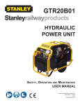
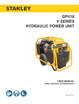
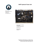
HYDRAULIC
POWER UNIT
USER MANUAL
Safety, Operation and Maintenance
© 2013 Stanley Black & Decker, Inc.
New Britain, CT 06053
U.S.A.
72464 4/2015 Ver. 9
2 ► HP TWIN8 User Manual
TABLE OF CONTENTS
SAFETY SYMBOLS...................................................................................................................................................4
SAFETY PRECAUTIONS...........................................................................................................................................5
TOOL STICKERS.......................................................................................................................................................7
HOSE TYPES.............................................................................................................................................................8
HOSE RECOMMENDATIONS...................................................................................................................................9
HTMA \ EHTMA REQUIREMENTS..........................................................................................................................10
PRE-OPERATION.................................................................................................................................................... 11
CONTROLS..............................................................................................................................................................12
START-UP................................................................................................................................................................12
MAINTENANCE.......................................................................................................................................................13
BATTERY MAINTENANCE................................................................................................................................13
CIRCUIT TESTING..................................................................................................................................................16
TROUBLESHOOTING.............................................................................................................................................17
SPECIFICATIONS....................................................................................................................................................18
ACCESSORIES.......................................................................................................................................................19
LOWER FRAME ILLUSTRATION............................................................................................................................20
LOWER FRAME PARTS LIST.................................................................................................................................21
HYDRAULIC GROUP ILLUSTRATION....................................................................................................................22
HYDRAULIC GROUP PARTS LIST.........................................................................................................................23
UPPER FRAME ILLUSTRATION AND PARTS LIST...............................................................................................24
HYDRAULIC FLOW.................................................................................................................................................25
CONTROL BLOCK DETAIL......................................................................................................................................26
HYDRAULIC & FUEL TANKS...................................................................................................................................27
IMPORTANT
To fill out a Product Warranty Validation form, and for information on your warranty,
visit Stanleyhydraulics.com and select the Company tab, Warranty.
(NOTE: The warranty Validation record must be submitted to validate the warranty).
SERVICING: This manual contains safety, operation, and routine maintenance instructions. Stanley Hydraulic Tools
recommends that servicing of hydraulic tools, other than routine maintenance, must be performed by an authorized
and certified dealer. Please read the following warning.
WARNING
SERIOUS INJURY OR DEATH COULD RESULT FROM THE IMPROPER REPAIR OR
SERVICE OF THIS TOOL.
REPAIRS AND / OR SERVICE TO THIS TOOL MUST ONLY BE DONE BY AN
AUTHORIZED AND CERTIFIED DEALER.
For the nearest authorized and certified dealer, call Stanley Hydraulic Tools at (503) 659-5660 and ask for a
Customer Service Representative.
HP TWIN8 User Manual ◄ 3
SAFETY SYMBOLS
Safety symbols and signal words, as shown below, are used to emphasize all operator, maintenance and repair actions which, if not strictly followed, could result in a life-threatening situation, bodily injury or damage to equipment.
This is the safety alert symbol. It is used to alert you to potential personal injury
hazards. Obey all safety messages that follow this symbol to avoid possible
injury or death.
DANGER
This safety alert and signal word indicate an imminently hazardous situation
which, if not avoided, will result in death or serious injury.
WARNING
This safety alert and signal word indicate a potentially hazardous situation
which, if not avoided, could result in death or serious injury.
CAUTION
This safety alert and signal word indicate a potentially hazardous situation
which, if not avoided, could result in death or serious injury.
CAUTION
This signal word indicates a potentially hazardous situation which, if not avoided, may result in property damage.
NOTICE
This signal word indicates a situation which, if not avoided, will result in damage
to the equipment.
IMPORTANT
This signal word indicates a situation which, if not avoided, may result in damage to the equipment.
Always observe safety symbols. They are included for your safety and for the protection of the tool.
LOCAL SAFETY REGULATIONS
Enter any local safety regulations here. Keep these instructions in an area accessible to the operator and maintenance personnel.
4 ► HP TWIN8 User Manual
SAFETY PRECAUTIONS
Tool operators and maintenance personnel must always
comply with the safety precautions given in this manual
and on the stickers and tags attached to the tool and
hose.
•
Do not inspect hoses and fittings for leaks by using
bare hands. “Pin-hole” leaks can penetrate the skin.
•
NEVER OPERATE THE POWER UNIT IN A
CLOSED SPACE. Inhalation of engine exhaust can
be fatal.
•
Do not operate a damaged, improperly adjusted
power unit.
•
Do not wear loose clothing or unbound long hair
when operating the tool. Loose items can get entangled with the tool and cause serious injury.
•
Keep all parts of your body away from the working
parts of the power unit.
•
Keep clear of hot engine exhaust.
•
Do not add fuel to the power unit while the power
unit is running or is still hot.
•
Do not operate the power unit if gasoline odor is
present.
•
Do not use flammable solvents around the power
unit engine.
•
Do not operate the power unit within 3.3 ft/1 m of
buildings, obstructions or flammable objects.
•
Do not reverse tool rotation direction by changing
fluid flow direction.
•
Establish a training program for all operators to ensure safe operation.
Allow power unit engine to cool before storing in an
enclosed space.
•
Do not operate the power unit unless thoroughly
trained or under the supervision of an instructor.
Always keep critical tool markings, such as labels
and warning stickers legible.
•
•
Always wear safety equipment such as goggles, ear
protection, breathing protection, head protection,
and safety shoes at all times when operating the
power unit and a hydraulic tool.
To avoid personal injury or equipment damage, all
tool repair, maintenance and service must only be
performed by authorized and properly trained personnel.
•
•
Do not inspect or clean the power unit while it is running. Accidental engagement of the unit can cause
serious injury.
Do not operate the machine on excessive slopes or
unstable terrain where “tip over” is a hazard.
•
Always use hoses and fittings rated at 2500 psi/172
bar with a 4 to 1 safety factor. Be sure all hose connections are tight. Do not exceed the rated limits of the equipment or
use the equipment for applications beyond its design capacity.
•
Be aware of surrounding hazards. Noise created by
the Power Unit and the tools it operates may mask
early indications of approaching hazards.
These safety precautions are given for your safety. Review them carefully before operating the tool and before
performing general maintenance or repairs.
Supervising personnel should develop additional precautions relating to the specific work area and local
safety regulations. If so, place the added precautions in
the space provided in this manual.
The HP TWIN8 Hydraulic Power Unit will provide safe
and dependable service if operated in accordance with
the instructions given in this manual. Read and understand this manual and any stickers and tags attached
to the tool and hoses before operation. Failure to do so
could result in personal injury or equipment damage.
•
•
•
•
•
Operator must start in a work area without bystanders. The operator must be familiar with all prohibited
work areas such as excessive slopes and dangerous terrain conditions.
Be sure all hoses are connected for correct flow direction to and from the tool being used.
HP TWIN8 User Manual ◄ 5
SAFETY PRECAUTIONS
•
Warning: Hydraulic fluid under pressure could cause
skin injection injury. If you are injured by hydraulic
fluid, get medical attention immediately.
•
Be observant of the hydraulic hoses lying about the
work area, they can be a tripping hazard.
•
Use proper lifting techniques when handling the
power unit, and do not over-reach.
•
Only use the Power Unit in well-ventilated areas. DO
NOT operate in explosive atmospheres, in closed
environments or near flammable substances.
•
Always be well-rested and mentally alert when operating the Power Unit and tools. DO NOT operate if
affected by medications, drugs or alcohol.
•
Keep clear of hot (engine) parts and exhaust.
•
Do not operate tools if oil temperature exceeds 140
°F/60 °C. Operation at high temperatures can cause
higher than normal temperatures at the tools which
can result in operator discomfort or injury.
•
Disconnect battery before servicing electrical components. Electrocution or burns could result from
improper contact.
•
Loading and unloading of the power unit is dangerous. Never attempt to load or unload the power unit
without loading ramps, loading dock or an over head
crane. Loading ramps must be strong enough, have
a low angle, and correct height. Load and unload the
power unit on a level surface. Never attempt to load
or unload the power unit if the ramp incline exceeds
15 degrees. Failure to follow these instructions may
result in serious injury or death.
•
Warning: Use of this tool on certain materials
during demolition could generate dust potentially
containing a variety of hazardous substances
such as asbestos, silica or lead. Inhalation of dust
containing these or other hazardous substances
could result in serious injury, cancer or death.
Protect yourself and those around you. Research
and understand the materials you are cutting.
Follow correct safety procedures and comply with
all applicable national, state or provisional health
and safety regulations relating to them, including,
if appropriate arranging for the safe disposal of the
materials by a qualified person.
6 ► HP TWIN8 User Manual
TOOL STICKERS
LOGO, TWIN8 DECAL P/N-205044
DASH, TWIN8, DECAL P/N-205043
STANLEY, HYD TANK, DECAL P/N-205049
LOGO TWIN8, HYD TANK DECAL P/N-205046
STANLEY, FUEL TANK DECAL P/N-205048
LOGO, TWIN8, FUEL TANK DECAL P/N-205045
SAFETY, TWIN8, DECAL P/N-205047
HP TWIN8 User Manual ◄ 7
HOSE TYPES
The rated working pressure of the hydraulic hose must be equal to or higher than the relief valve setting on the hydraulic system. There are three types of hydraulic hose that meet this requirement and are authorized for use with
Stanley Hydraulic Tools. They are:
Certified non-conductive — constructed of thermoplastic or synthetic rubber inner tube, synthetic fiber braid
reinforcement, and weather resistant thermoplastic or synthetic rubber cover. Hose labeled certified nonconductive is the only hose authorized for use near electrical conductors.
Wire-braided (conductive) — constructed of synthetic rubber inner tube, single or double wire braid reinforcement, and weather resistant synthetic rubber cover. This hose is conductive and must never be used near
electrical conductors.
Fabric-braided (not certified or labeled non-conductive) — constructed of thermoplastic or synthetic rubber inner tube, synthetic fiber braid reinforcement, and weather resistant thermoplastic or synthetic rubber cover. This
hose is not certified non-conductive and must never be used near electrical conductors.
HOSE SAFETY TAGS
To help ensure your safety, the following DANGER tags are attached to all hose purchased from Stanley Hydraulic
Tools. DO NOT REMOVE THESE TAGS.
If the information on a tag is illegible because of wear or damage, replace the tag immediately. A new tag may be
obtained from your Stanley Distributor.
D A N G E R
D A N G E R
1.
FAILURE TO USE HYDRAULIC HOSE LABELED AND CERTIFIED AS NON-CONDUCTIVE
WHEN USING HYDRAULIC TOOLS ON OR NEAR ELECTRIC LINES MAY RESULT IN
DEATH OR SERIOUS INJURY.
FOR PROPER AND SAFE OPERATION MAKE SURE THAT YOU HAVE BEEN PROPERLY TRAINED IN CORRECT PROCEDURES REQUIRED FOR WORK ON OR AROUND
ELECTRIC LINES.
2.
BEFORE USING HYDRAULIC HOSE LABELED AND CERTIFIED AS NON-CONDUCTIVE
ON OR NEAR ELECTRIC LINES. WIPE THE ENTIRE LENGTH OF THE HOSE AND FITTING WITH A CLEAN DRY ABSORBENT CLOTH TO REMOVE DIRT AND MOISTURE AND
TEST HOSE FOR MAXIMUM ALLOWABLE CURRENT LEAKAGE IN ACCORDANCE WITH
SAFETY DEPARTMENT INSTRUCTIONS.
3.
DO NOT EXCEED HOSE WORKING PRESSURE OR ABUSE HOSE. IMPROPER USE
OR HANDLING OF HOSE COULD RESULT IN BURST OR OTHER HOSE FAILURE.
KEEP HOSE AS FAR AWAY AS POSSIBLE FROM BODY AND DO NOT PERMIT DIRECT
CONTACT DURING USE. CONTACT AT THE BURST CAN CAUSE BODILY INJECTION
AND SEVERE PERSONAL INJURY.
4.
HANDLE AND ROUTE HOSE CAREFULLY TO AVOID KINKING, ABRASION, CUTTING, OR
CONTACT WITH HIGH TEMPERATURE SURFACES. DO NOT USE IF KINKED. DO NOT
USE HOSE TO PULL OR LIFT TOOLS, POWER UNITS, ETC.
5.
CHECK ENTIRE HOSE FOR CUTS CRACKS LEAKS ABRASIONS, BULGES, OR DAMAGE TO COUPLINGS IF ANY OF THESE CONDITIONS EXIST, REPLACE THE HOSE
IMMEDIATELY. NEVER USE TAPE OR ANY DEVICE TO ATTEMPT TO MEND THE HOSE.
6.
AFTER EACH USE STORE IN A CLEAN DRY AREA.
SEE OTHER SIDE
SIDE 1
SEE OTHER SIDE
(Shown smaller than actual size)
DO NOT REMOVE THIS TAG
DO NOT REMOVE THIS TAG
THE TAG SHOWN BELOW IS ATTACHED TO “CERTIFIED NON-CONDUCTIVE” HOSE
SIDE 2
D A N G E R
D A N G E R
1.
DO NOT USE THIS HYDRAULIC HOSE ON OR NEAR ELECTRIC LINES. THIS HOSE IS
NOT LABELED OR CERTIFIED AS NON-CONDUCTIVE. USING THIS HOSE ON OR NEAR
ELECTRICAL LINES MAY RESULT IN DEATH OR SERIOUS INJURY.
5.
CHECK ENTIRE HOSE FOR CUTS CRACKS LEAKS ABRASIONS, BULGES, OR DAMAGE TO
COUPLINGS IF ANY OF THESE CONDITIONS EXIST, REPLACE THE HOSE IMMEDIATELY.
NEVER USE TAPE OR ANY DEVICE TO ATTEMPT TO MEND THE HOSE.
2.
FOR PROPER AND SAFE OPERATION MAKE SURE THAT YOU HAVE BEEN PROPERLY
TRAINED IN CORRECT PROCEDURES REQUIRED FOR WORK ON OR AROUND ELECTRIC LINES.
6.
AFTER EACH USE STORE IN A CLEAN DRY AREA.
3.
DO NOT EXCEED HOSE WORKING PRESSURE OR ABUSE HOSE. IMPROPER USE OR
HANDLING OF HOSE COULD RESULT IN BURST OR OTHER HOSE FAILURE. KEEP HOSE
AS FAR AWAY AS POSSIBLE FROM BODY AND DO NOT PERMIT DIRECT CONTACT
DURING USE. CONTACT AT THE BURST CAN CAUSE BODILY INJECTION AND SEVERE
PERSONAL INJURY.
4.
HANDLE AND ROUTE HOSE CAREFULLY TO AVOID KINKING, CUTTING, OR CONTACT
WITH HIGH TEMPERATURE SURFACES. DO NOT USE IF KINKED. DO NOT USE HOSE TO
PULL OR LIFT TOOLS, POWER UNITS, ETC.
SEE OTHER SIDE
SEE OTHER SIDE
SIDE 1
SIDE 2
(Shown smaller than actual size)
8 ► HP TWIN8 User Manual
DO NOT REMOVE THIS TAG
DO NOT REMOVE THIS TAG
THE TAG SHOWN BELOW IS ATTACHED TO “CONDUCTIVE” HOSE.
All hydraulic hose must meet or exceed
specifications as set forth by SAE J517.
All hydraulic hose must have at least a rated
minimum working pressure equal to the maximum hydraulic system relief valve setting.
This chart is intended to be used for hydraulic
tool applications only based on Stanley Hydraulic Tools tool operating requirements and
should not be used for any other applications.
The chart to the right shows recommended
minimum hose diameters for various hose
lengths based on gallons per minute (gpm)/
liters per minute (lpm). These recommendations are intended to keep return line pressure
(back pressure) to a minimum acceptable level to ensure maximum tool performance.
Tool to Hydraulic Circuit Hose
Recommendations
15-34
MM
Inside Diameter
INCH
USE
(Press/Return)
PSI
up to 10
up to 3
3/8
10
Both
2250
49-60
13-16
FLOW >>>
RETURN
<<< FLOW
PRESSURE
26-100
up to 25
100-200
51-100
up to 50
100-300
51-100
up to 50
26-100
up to 25
8-30
up to 8
30-60
15-30
up to 15
30-90
15-30
up to 15
7.5-30
up to 7.5
19
25.4
16
19
19
25.4
5/8
3/4
3/4
1
19
3/4
1
16
3/4
16
19
3/4
5/8
16
5/8
5/8
16
13
13
10
5/8
1/2
1/2
3/8
175
175
175
175
175
175
175
175
175
175
175
175
175
175
175
2500
2500
2500
2500
2500
2500
2500
2500
2500
2500
2500
2500
2500
2500
2500
Both
Both
Both
Both
Pressure
Return
Both
Pressure
Return
Pressure
Return
Pressure
Return
Pressure
Return
PRESSURE
Figure 1. Typical Hose Connections
49-60
38-49
10-13
13-16
19-40
5-10.5
38-49
19-40
5-10.5
10-13
19-40
5-10.5
38-49
15-23
10-13
15-23
4-6
155
BAR
Min. Working Pressure
Certified Non-Conductive Hose - Fiber Braid - for Utility Bucket Trucks
METERS
Hose Lengths
FEET
Conductive Hose - Wire Braid or Fiber Braid -DO NOT USE NEAR ELECTRICAL CONDUCTORS
4-6
4-9
LPM
Oil Flow
GPM
HOSE RECOMMENDATIONS
HYDRAULIC CIRCUIT
RETURN
HP TWIN8 User Manual ◄ 9
HTMA / EHTMA REQUIREMENTS
HTMA / EHTMA REQUIREMENTS
HTMA
HYDRAULIC SYSTEM REQUIREMENTS
TYPE I
Nominal Operating Pressure
(at the power supply outlet)
4-6 gpm
(15-23 lpm)
1500 psi
(103 bar)
TOOL TYPE
TYPE II
TYPE RR
7-9 gpm
(26-34 lpm)
1500 psi
(103 bar)
9-10.5 gpm
(34-40 lpm)
1500 psi
(103 bar)
System relief valve setting
(at the power supply outlet)
2100-2250 psi
(145-155 bar)
2100-2250 psi
(145-155 bar)
2200-2300 psi
(152-159 bar)
2100-2250 psi
(145-155 bar)
Maximum back pressure
(at tool end of the return hose)
250 psi
(17 bar)
250 psi
(17 bar)
250 psi
(17 bar)
250 psi
(17 bar)
Measured at a max. fluid viscosity of:
(at min. operating temperature)
400 ssu*
400 ssu*
400 ssu*
400 ssu*
(82 centistokes) (82 centistokes) (82 centistokes) (82 centistokes)
Temperature: Sufficient heat rejection
capacity to limit max. fluid temperature to:
(at max. expected ambient temperature)
140° F
(60° C)
Flow Range
140° F
(60° C)
140° F
(60° C)
TYPE III
11-13 gpm
(42-49 lpm)
1500 psi
(103 bar)
140° F
(60° C)
3 hp
5 hp
6 hp
7 hp
Min. cooling capacity at a temperature
(2.24 kW)
(3.73 kW)
(5.22 kW)
(4.47 kW)
difference of between ambient and fluid
40° F
40° F
40° F
40° F
temps
(22° C)
(22° C)
(22° C)
(22° C)
NOTE:
Do not operate the tool at oil temperatures above 140° F (60° C). Operation at higher temperatures can cause operator
discomfort at the tool.
Filter
Min. full-flow filtration
Sized for flow of at least:
(For cold temp. startup and max.
dirt-holding capacity)
25 microns
30 gpm
(114 lpm)
Hydraulic fluid Petroleum based
(premium grade, anti-wear, non-conductive)
Viscosity (at min. and max. operating temps)
100-400 ssu*
25 microns
30 gpm
(114 lpm)
25 microns
30 gpm
(114 lpm)
100-400 ssu*
100-400 ssu*
(20-82 centistokes)
25 microns
30 gpm
(114 lpm)
100-400 ssu*
NOTE:
When choosing hydraulic fluid, the expected oil temperature extremes that will be experienced in service determine the
most suitable temperature viscosity characteristics. Hydraulic fluids with a viscosity index over 140 will meet the requirements
over a wide range of operating temperatures.
*SSU = Saybolt Seconds Universal
EHTMA
HYDRAULIC SYSTEM
REQUIREMENTS
CLASSIFICATION
B
C
D
Nominal Operating Pressure
(at the power supply outlet)
3.5-4.3 gpm
(13.5-16.5 lpm)
1870 psi
(129 bar)
4.7-5.8 gpm
(18-22 lpm)
1500 psi
(103 bar)
7.1-8.7 gpm
(27-33 lpm)
1500 psi
(103 bar)
9.5-11.6 gpm
(36-44 lpm)
1500 psi
(103 bar)
11.8-14.5 gpm
(45-55 lpm)
1500 psi
(103 bar)
System relief valve setting
(at the power supply outlet)
2495 psi
(172 bar)
2000 psi
(138 bar)
2000 psi
(138 bar)
2000 psi
(138 bar)
2000 psi
(138 bar)
Flow Range
NOTE: These are general hydraulic system requirements. See tool specification page for tool specific requirements
10 ► HP TWIN8 User Manual
PRE-OPERATION
PREPARATION FOR USE
Do not operate the power unit until you have read the engine
operating and maintenance instructions manual furnished
with the unit.
1. ENGINE CRANKCASE OIL LEVEL
Always check the oil level before starting the engine. Make
sure the oil level is at the FULL MARK on the dipstick. Do not
overfill. Use detergent oil classified “For Service SF, SG, SH,
SJ or higher” as specified in the engine operators manual.
Do not use special additives. Outdoor temperatures determine the proper oil viscosity for the engine. Use the chart to
select the best viscosity for the outdoor temperature range
expected.
°C
104
40
86
30
14
HTMA-approved quick disconnect couplings are
installed to hydraulic hoses so that the direction of
oil flow is always from the male to the female quick
disconnect as shown on page 9. Quick disconnect
couplings and hose fittings are selected so that
additional fittings such as reducer or adapter fittings are
not required.
If adapter fittings are used, they must be approved
steel hydraulic fittings meeting a minimum operating
pressure rating of 2500 psi/172 bar. Do not use
galvanized pipe fittings or black pipe fittings.
Use thread tape or pipe joint compound when installing
quick disconnect couplings to hose or tool fittings.
Follow the instructions furnished with the selected
thread sealant. DO NOT OVERTIGHTEN THE
FITTINGS.
3. HYDRAULIC FLUID
10
5W-30
32
Synthetic 5W-30
50
20
10W-30 **
68
SAE 30 *
°F
QUICK DISCONNECT COUPLERS
0
RECOMMENDED HYDRAULIC OILS
-10
Below is a list of recommended oils by brand.
Biodegradable
Description
CITGO
No
Hydurance AW32
AMS Oil
No
HVH 32
Exxon Mobil
No
Univis HVI26*
* Below 40°F (4°C) the use of SAE 30 will result in hard
starting.
Exxon Mobil
No
DTE 10 Excel
Shell
No
S2 V 32
** Above 80°F (27°C) the use of 10W-30 may cause
increased oil consumption. Check oil level more
frequently.
Chevron
No
Rando HDZ 32
Conoco Phillips
No
Unax AW-WR-32
Clarion (CITGO)
Yes
Green Bio 32
Exxon Mobil
Yes
EAL 224H
Chevron
Yes
Clarity AW32
Terresolve
Yes
Envirologic 132
Shell
Yes
Naturelle HF-E-32
-4
-22
Brand
-20
-30
2. ENGINE FUEL LEVEL
Check the fuel level. If low, fill with clean, fresh unleaded
gasoline with a minimum of 87 octane. Gasoline with up to
10% ethanol (gasohol) is acceptable.
*Recommended for extreme cold temperatures
3. HYDRAULIC CONNECTIONS
The recommended hose length is 25 ft/8 m with a
1/2 inch/12.7 mm inside diameter. The hoses must
have a working pressure rating of at least 2500
psi/175 bar. Each hose end must have male thread
ends compatible with HTMA (HYDRAULIC TOOL
MANUFACTURERS ASSOCIATION) quick disconnect
fittings (NPT type threads). (See pages 8 and 9).
HP TWIN8 User Manual ◄ 11
OPERATION
CONTROLS (DUAL CIRCUIT)
5. BATTERY
The supplied 12-Volt DC battery is a sealed nonspillable, maintenance-free battery and is fully charged.
Throttle Control Lever
Starter Switch
Make sure the battery cables are tight and charging
circuit functions are operating properly.
NOTICE
A fully charged battery should read 12.8V -13.0V.
Caution, overcharging can harm your battery beyond
recovery. When using an automatic charger, refer to
the charger manufacturer’s instructions.
Flow Control Lever(s) In Off Position
NOTICE
If the engine runs out of gas or dies during operation
and the ignition switch is left in the ON or RUN
position, this could drain the battery. Make sure the
ignition switch is returned to the OFF position.
When the throttle control lever is in the far left position,
it will produce 5 GPM to both circuits at the same time
and with the lever in the far right position will produce 8
GPM to both circuits. This allows two tools that can run
simultaneously at 5 or 8 GPM.
The flow control levers when turned “ON” (up position)
turns on flow to the tool or tools depending on if you
are using one or both circuits.
STARTUP
COUPLERS (HOSE CONNECTIONS)
Top Male Quick Disconnect
Couplers (Pressure Fluid Out)
1. Before starting the engine check the engine oil and
hydraulic fluid level.
2. Check to make sure the flow Control levers are in
the OFF position (Down), the power unit will not
start if the levers are in the “UP” position (ON).
3. Connect hoses and the tool as described on page
9.
4. It is not necessary to choke the engine, it is
equipped with a “Electronic Fuel Management
System” that does not have a manual choke.
5. Set the throttle control lever to the left (5-GPM)
setting. Once the unit starts and is warmed-up the
lever can be moved to the 8-GPM setting if desired.
6. Turn the Ignition Switch to the START position.
After the engine starts, release the switch.
Bottom Female Quick Disconnect
Couplers (Return Fluid In)
Facing the control panel, the top (2) male couplers are
the PRESSURE FLUID OUT fittings. The bottom (2)
female quick disconnect couplers are the RETURN
FLUID IN. Their are two independent circuits, one on
the left and one on the right, each controlled by the
adjacent lever.
12 ► HP TWIN8 User Manual
7. Allow the engine to warm up.
8. Turn on the flow to the tool by lifting the “Flow
Control Levers” up into the on position, lift both
levers if running two circuits (two Tools).
SHUTDOWN
1. Ensure the flow control levers are in the OFF
position (Down).
2. Move the Ignition Switch to the OFF position.
MAINTENANCE
COLD WEATHER STARTUP
1. Use the procedures described under “STARTUP”
and then follow the procedure below.
2. Hydraulic fluids are thicker in cold weather.
Therefore, it is recommended that the engine
be run at low idle long enough to bring the fluid
temperature up to a minimum of 50 °F/10 °C.
3. If the tools and tool hoses are cold, it is
recommended to allow hydraulic fluid to circulate
through the tool hoses until warm before using the
tool.
ENGINE MAINTENANCE
Follow the maintenance schedule and general
maintenance instructions and emissions control
maintenance in the engine operators manual furnished
with the power unit.
Fuel system emissions maintenance:
•
Check the fuel system emissions components
once a year to verify that the components are in
good condition and do not show signs of leakage. If
leakage is found, replace part.
•
Check fuel lines, tank, cap and fittings frequently
for cracks or leaks. Replace if necessary.
•
Clean the fuel cap area of dirt and debris.
•
Replacement parts must be the same and installed
in the same position as the original parts.
•
Change the hydraulic filter element every 200
hours of operation. Change more often if cold,
moist or dusty conditions exist.
•
Check oil cooler for debris. Remove debris with air
pressure.
BATTERY MAINTENANCE
• If the power unit is not in use for two or more months,
check the battery once a month and charge if the battery voltage is below 12.5V. Charge at 1.3A for 5-10
hours.
• If the battery voltage is below 12.0V, charge at
1.3A for 12-18 hours, let the battery sit for 1-2 hours
and check the voltage. If the voltage is not 12.5V or
greater, replace the battery.
• Always charge using a charger as rated as close to
1.3A as possible.
• Checking battery voltage and charging can be done
through the 12V marine plug on the battery cover when
using an appropriate adapter.
STORAGE
•
Clean the unit thoroughly before storage. Do not
use water pressure.
•
Always store the unit in a clean and dry facility.
•
If the unit will be stored for a prolonged period
(over 30 days), add a fuel additive to the fuel tank
to prevent the fuel from gumming. Run engine for 2
minutes to circulate the additive throughout the fuel
system.
HYDRAULIC SYSTEM MAINTENANCE
•
•
Check hydraulic fluid level daily. Add fluid per
specifications in this manual. (See “HYDRAULIC
FLUID” under the section titled “PRE-OPERATION”
page 11.
Remove condensed moisture from the hydraulic
fluid by pumping the hydraulic fluid into a 5
gal/20 L. container through the pressure hose.
Make sure the engine is at idle when performing
this procedure. When the hydraulic reservoir is
empty turn the engine off immediately.
•
Allow the fluid to sit long enough for the water to
settle to the bottom of the container. Slowly pour
the fluid back into the hydraulic tank, avoiding the
water at the bottom of the container.
•
Each day, check hydraulic lines and fittings for
leaks, kinks, etc. Do not use your hand to perform
this check.
WARNING
When storing fuel or equipment with fuel in the tank,
store away from appliances that have pilot lights or
other ignition sources, they can ignite fuel vapors.
•
Replace crankcase oil with new oil.
•
Remove spark plugs and pour approximately 1
ounce (30 ml) of engine oil into each cylinder.
Replace spark plugs and crank the engine slowly to
distribute the oil.
•
Check hydraulic reservoir for water. If water is
found, change the oil and circulate it through the
tool hose and tool. (See “HYDRAULIC SYSTEM
MAINTENANCE” earlier in this section).
•
Disconnect tool hoses.
HP TWIN8 User Manual ◄ 13
MAINTENANCE
Standard Maintenance Schedule
Hours Daily
5
25
50
75
100
125
150
175
200
Foam Air Pre-Cleaner
C
I
I
R
I
I
I
R
Paper Air Filter
C
R
R
R
Engine
Inline Fuel Filter
R
Spark Plugs (Gap-0.030 in (0.76 mm)
R
Engine Oil Filter
R
R
R
R
R
Engine Oil
R
R
R
R
R
Engine Oil Level
I
Remove Dirt & Debris With Brush
I
C
Clean Air Cooling System (don’t use water)
C
I
Hydraulic Fluid Level
R
Hydraulics
Hydraulic Fluid
R
Remove Condensed Moisture
R
I
Check For Leaks, Kinks, etc.
I
Hydraulic Fluid Filter
I
I
R
C
Clean Hydraulic Fluid Cooler
I
Relief Valve Settings
C
I
I
I
Heavy Duty Maintenance Schedule
Hours Daily
5
25
50
75
100
125
150
175
200
Foam Air Pre-Cleaner
C*
R
I
R
I
R
I
R
Paper Air Filter
C*
R
R
R
R
R
Engine
Inline Fuel Filter
R
Spark Plugs (Gap-0.030 in (0.76 mm)
Engine Oil Filter
Engine Oil
Engine Oil Level
I
Remove Dirt & Debris With Brush
I
Hydraulic Fluid Level
R
R
R
R
R
R
R
R
R
R
R
R
R
R
R
R
R
R
C
C
R
Hydraulics
Remove Condensed Moisture
Relief Valve Settings
R
R
R
R
I
R
I
R
C
C
C
C
I
I
I
I
I
Hydraulic Fluid Filter
Clean Hydraulic Fluid Cooler
C
I
Hydraulic Fluid
Check For Leaks, Kinks, etc.
R
R
C
Clean Air Cooling System (don’t use water)
R
**
C
Clean (* In dusty conditions or when airborne debris is present, clean more often).
I
Inspect (** In dusty conditions or when airborne debris is present, inspect the back side of cooler often).
R
Replace
For additional maintenance information see the Briggs & Stratton engine operator’s manual that was supplied
with the power unit.
14 ► HP TWIN8 User Manual
MAINTENANCE
FUEL FILTER, FUEL LINE
FROM TANK TO FILTER
“GG” CONNECTION
See Page 27
SEE PAGE 19 FOR REPLACEMENT FILTER PART NUMBERS
ENGINE OIL
COOLER
HYDRAULIC OIL FILTER
HYDRAULIC
FUEL LINE FROM TANK
TO FUEL PUMP
TANK
THROTTLE
CABLE
FUEL VAPOR LINE
FROM CARBON CANISTER
TO ENGINE (CONNECTION “HH”)
See Page 27
ENGINE OIL CHECK &
FILL (DIP STICK)
FUEL TANK
QUICK ENGINE
OIL DRAIN
AIR CLEANER
SPARK PLUG
HYDRAULIC
OIL COOLER
HP TWIN8 User Manual ◄ 15
CIRCUIT TESTING
GENERAL
Tests and adjustments should be performed
periodically to ensure the power unit is operating
at maximum efficiency. Use a calibrated flow and
pressure tester. This tester can be used to isolate
problems in both the engine and hydraulic system prior
to any power unit disassembly.
TESTING THE HYDRAULIC CIRCUIT
The following tests can be performed to ensure that
the hydraulic pump is supplying the correct flow and
pressure and that the system relief valve is operating
properly.
During these tests, make sure the engine is warm and
operating smoothly. If test results are not as specified,
refer to the troubleshooting table in this section for
possible causes.
TESTING THE 5 OR 8 GPM CIRCUIT
To test the circuit, proceed as follows:
Throttle Control Lever
4. Check that the tester restrictor valve is fully open
(counterclockwise) on the flow and pressure tester.
5. Start the engine and allow it to run until warm.
6. With the throttle control in the far left position, the
(5-GPM) circuit can be tested, or moving the lever
to the far right will allow testing the (8-GPM) circuit.
a. 5-GPM Range 4-6 gpm/15-23 lpm
b. 8-GPM Range 7-9 gpm/26.5-34 lpm
7. Slowly turn the restrictor valve clockwise while
watching the pressure gauge. The flow rate shown
above in step 6 should stay at the selected flow
range.
8. When the pressure reaches 2100–2200 psi/145–
152 bar, the relief valve should begin to open.
The pressure at which the relief valve just begins
to open is commonly referred to as the “cracking
pressure”. At the “cracking pressure,” the flow rate
should start to drop because the relief valve is
allowing fluid to bypass to the hydraulic reservoir.
The “cracking pressure” is preset at the factory
and if it is not within the above range (2100-2200)
psi, the relief valve must be re-set as follows: The
relief valves are located on the control block which
is directly behind the couplers on the dash panel
(See item 10, pg-22) for location. Use a wrench to
loosen the nut on the relief valve.
9. Use an Allen wrench to adjust the relief valve.
Turn clockwise to raise the pressure and
counterclockwise to reduce the pressure. Tighten
the nut and retest.
10. Check both the 5 and 8 gallon flow settings and
then follow the same procedure to test the other
circuit (each circuit has its own relief valve).
Flow Control Lever(s)
1. Install a calibrated flow and pressure tester across
the two hose ends (where the tool would normally
be connected).
2. Set both flow control levers to the OFF (down)
position.
3. Set the throttle control lever to the far left for 5
GPM, after the engine is started you can leave the
lever in this position if you are testing the 5 GPM
circuit or move the lever to the far right to test the 8
GPM circuit.
16 ► HP TWIN8 User Manual
TROUBLESHOOTING
Problem
Engine will not start
Cause
Solution
Battery not connected.
Attach battery cables, check wires.
Weak battery.
Test battery, charge or replace.
No fuel.
Add fuel.
Fuel filter plugged.
Replace fuel filter.
Defective spark plugs.
Remove plugs, check gap, clean or
replace.
Low Engine Oil
Check Oil Level
Flow Control Levers in the “ON”
position.
Move the levers to the off position.
Fluid blowing out of fluid reservoir
vent.
Hydraulic tank overfilled.
Correct the fluid level.
Pump suction leak.
Check suction connections. Tighten
if necessary.
Hydraulic tool won’t operate.
Flow control lever(s) not in the (ON) Check that the flow control lever(s)
position.
are in the ON position.
Incorrect hose connection to tool.
Make sure the tool hose circuit
goes from left (pressure) fitting to
tool and back to the right fitting
(return). Fluid always flows from the
male to female fittings.
Quick disconnect fittings defective.
Detach from hose, connect set
together and check for free flow.
Hydraulic fluid level low.
Check for correct fluid level. Fill
using the recommended fluid.
Relief valve stuck open.
Adjust or replace valve.
Suction hose kinked.
Make sure suction hose from
fluid reservoir to pump inlet has a
smooth curve.
Tool is defective.
Refer to tool manual.
HP TWIN8 User Manual ◄ 17
SPECIFICATIONS
HP TWIN8 SPECIFICATIONS
Engine:.............................................................................................................. 27 hp OHV, Briggs & Stratton Engine
Output Capacity (Dual 5 or Dual 8 Circuits)....................... Two 5 gpm/20 lpm Circuits or Two 8 gpm/30 lpm Circuits
Length:............................................................................................................................................. 37.5 in./95.25 cm
Width:............................................................................................................................................... 25.75 in./65.4 cm
Height:.................................................................................................................................................... 30 in./76.2cm
Weight (Wet): ........................................................................................................................................360 lbs/163 kg
Fuel Tank Capacity:.............................................................................................................................. 4.7 gal./17.8 ltr
Estimated Gas Consumption Per Hour................................................................................................... 2.5 gal/9.4 ltr
Hydraulic Reservoir Capacity:.............................................................................................................. 3.2 gal./12.1 ltr
Relief Valve “Crack” Setting............................................................................................................... 2100 psi/145 bar
Full Relief Setting.............................................................................................................................. 2500 psi/172 bar
Nominal Pressure.............................................................................................................................. 1500 psi/103 bar
Max Pressure.................................................................................................................................... 2000 psi/138 bar
Circuit Type.............................................................................................................................................. Open Center
HTMA/EHTMA Category......................................................................................................................... Type 1 and 2
C
D
POWER UNITS & GAS/FUEL DRIVEN EQUIPMENT: A1. Federal Emission Component Compliance 40CFR part
1060.120 Stanley warrants all fuel system emission components for 2 years from the date of original purchase
provided there has been no abuse, neglect, modifications, or improper maintenance.
Components covered. The emission-related warranty covers all components whose failure would increase the
evaporative emissions. Your emission-related warranty does not cover components whose failure would not
increase evaporative emissions. Coverage under this warranty extends only to the following parts; fuel tank,
fuel cap, fuel hose and vapor hose from the fuel tank to the engine and any connectors that are apart of the fuel
system.
The equipment is designed, built, and equipped so it conforms at the time of sale to the ultimate purchaser and
each subsequent purchaser and is in compliance with 40 C.F.R. 1060.120 standards. The equipment is free from
defects in materials and workmanship that may keep it from meeting these requirements.
18 ► HP TWIN8 User Manual
ACCESSORIES & FILTERS
ACCESSORIES
Coupler Male, Parker SAE.................................................................................................................................72398
Coupler Female, Parker SAE.............................................................................................................................72397
Coupler Set Male & Female, Parker SAE..........................................................................................................72396
Flow and Pressure Tester...................................................................................................................................04182
Hose Assy, 50 ft., with couplers ........................................................................................................................31848
Hose Assy, 25 ft., with couplers ........................................................................................................................31972
FILTERS
MODEL
HP28B02
ENGINE
OIL FILTER
AIR FILTER
FUEL FILTER
HYDRAULIC
OIL FILTER
18384
205053
205057
40408
HP TWIN8 User Manual ◄ 19
LOWER FRAME ILLUSTRATION
Item 5 pressure switch (not pictured)
mounts next to engine oil filter.
12
5
1
31
15
17
13
3
16
11
30
Item 26 control
block on pg 22
mounts to backside
of this plate.
10
14
6
10
10
EE
7
10
9
19
Item 19 mounts
inside lower
frame on axles
22
20
26
10
10
23
CC
21
16
3
29
8
2
24
BB
CONNECTION
see pg 27
25
DD
10
3
18
10
28
DD
10
AA
CONNECTION
see pg 27
10
4
DD
3
20 ► HP TWIN8 User Manual
10
Item 24 mounts
inside lower
frame using
fasteners item 10
CC above
LOWER FRAME PARTS LIST
ITEM
P/N
QTY
DESCRIPTION
1
12470
2
HHCS 10-24UNCX0.875
2
12787
4
FLANGE NUT 5/16-18
3
19534
6
HEX FLANGE BOLT 3/8-16 X 1
4
21713
2
VIBRATION MOUNT
5
31765
1
PRESSURE SWITCH
6
40369
2
WIRE BOOT
7
59074
6
HEX FLANGE BOLT 1/4-20 X 1/2
8
67511
2
RUBBER MOUNT
9
71937
4
HEX FLNG BOLT 3/8-16 X 1
10
71939
28
HEX FLANGE BOLT 1/4-20 X 3/4
11
72402
1
STARTER SOLENOID
12
72403
1
MUFFLER
13
72412
1
CLAMP 2.5 - 3.5 IN
14
72413
1
SOLENOID GROUND STRAP
15
72448
1
BRIGGS M49 27-HP
16
371067 2
WASHER 3/8" I.D.
17
208887 1
THROTTLE CABLE ASSY
18
202725 1
SKID PLATE, POWER UNIT
19
202726 1
AXLE BRACE, POWER UNIT
20
202731 1
ASSEMBLY, LOWER FRAME
21
203031 2
TIRE/WHEEL 4.10/3.50-6 FF
22
203034 1
TIEDOWN, BATTERY
23
203036 1
BATTERY, SEALED, 12V, 13AH
24
203038 1
ASSY, ROTATION STOP
25
203040 1
ASSY, GRILL, AIR INTAKE
26
203222 4
CAPSCREW 1/4-20UNCX1/2
28
203254 1
SUPPORT FOOT ASEMBLY
29
203411
CLIP NUT 1/4-20 .125-.156 GRIP
30
204331 2
WASHER 1/4 NEOPRENE
31
204332 1
KNOB, TAPERED, RED
72439
WIRE HARNESS
(NOT PICTURED)
1
1
HP TWIN8 User Manual ◄ 21
HYDRAULIC GROUP ILLUSTRATION
Connects to item 10 EE on Connects to hose (Item
36) at left (see FF) Connects to hose (Item
lower frame, see pg 20
37) at left (see JJ)
Connects to (Item
7) below
36
11
11
34
12
37
11
FF
9
JJ
Connects to back
of control block,
item 26 Below
48
9
7
49
35
32
19
2
1
18
16
26
10
31
33
21
13
22
3
46
4
23
40
29
47
30
25
44
20
14
Connects to item
24 on pg-20 inside
lower frame.
15
28
See page 26 for
close-up of Control
Block
See pg-20 for
38
mounting location
of Item 26 Control
Block
9
Connects to
lower fittings
on Hyd tank
45
24
45
5
17
11
9
11
9
11
42
22 ► HP TWIN8 User Manual
HYDRAULIC GROUP PARTS LIST
ITEM
P/N
QTY
WASHER
35
203222
4
CAPSCREW 1/4-20UNCX1/2
2
RETAINING RING
36
203232
1
06988
2
BACK-UP RING -018
HOSE, COOLER-FILTER
04306X20.25
06989
2
O-RING
37
203233
1
5
10793
2
HSHCS 3/8-16 X 1-1/4
HOSE, COOLER-BLOCK
04306X30.00
7
40364
1
ELBOW 45 3/4 SAE TO 3/4
BARB
38
203245
2
HOSE, PRESSURE, PUMPBLKHD
9
59104
6
HOSE BARB 12SAE 3/4 HOSE
40
203246
2
JAM NUT
10
59131
2
RELIEF VALVE
42
203247
2
11
62199
10
HOSE CLAMP
HOSE TANK-PUMP
04306X21.00
12
71908
1
OIL COOLER
44
204332
2
KNOB, TAPERED, RED
45
204538
2
CONNECTOR, -10 SAE-5/8
46
204539
1
HSHCS 7/16-20 X 1.00
47
204808
1
VALVE ASSY, ATM
48
204839
1
TEE, RUN, -12 SAE
49
204840
1
HOSE, BLOCK-FILTER
04306X14.5
ITEM
P/N
QTY
1
04216
2
2
04313
3
4
13
DESCRIPTION
PARTS NOLONGER USED
DESCRIPTION
14
72397
2
COUPLER FEMALE, PARKER
15
72398
2
COUPLER MALE, PARKER
16
72414
2
MICRO LIMIT SWITCH
17
72425
1
HYDRAULIC PUMP, DUAL
18
72455
4
CAPSCREW 4-40 x1/2 HSBH
19
72521
1
SQUARE KEY-.25 X .75
20
350237
1
HOLLOW HEX PLUG - 8 SAE
21
202740
2
ASSY, MANIFOLD TUBE
22
203024
1
COUPLER, PUMP/FAN
NOTE:
23
203025
1
BUSHING, TAPER LOCK, 5/8"
24
203026
1
NUT, COUPLER, PUMP/FAN
CONTROL BLOCK ASSEMBLY P/N-203051
(INCLUDES THE FOLLOWING)
25
203046
1
ASSY, TORQUE ARM
Item 1 thru 4, 10, 16, 18, 26, 28 thru 30.
26
203049
1
CONTROL BLOCK, DUAL
(SEE NOTE FOR COMPLETE
ASSEMBLY)
COUPLER SET 72396 (INCLUDES MALE AND
FEMALE)
28
203052
1
SPOOL, ON-OFF, RH
29
203053
1
SPOOL, ON-OFF, LH
30
203054
2
ROD, ON-OFF SPOOL
31
203063
2
CONNECTOR, -8 SAE-1/2
ORFS
32
203064
1
BLOWER WHEEL, 9.125X1.75
203067
1
33
34
PART NOLONGER USED
ASSY, HOUSING, BLOWER,
9"
HP TWIN8 User Manual ◄ 23
7
6
TION
4
UPPER FRAME ILLUSTRATION & PARTS LIST
ELEASE
13
6
7
2
1
5
12
11
9
10
14
14
8
3
DD CONNECTION Mounts
to Lower Frame see
Fastener DD pg 20
15
14
NOTE: Complete Upper Frame
Assembly P/N-206975 Includes
the Following (Items 4 thru 7 and
Items 11 thru 14).
4
ITEM
P/N
QTY DESCRIPTION
ITEM
P/N
QTY DESCRIPTION
1
60946
1
HOUR METER
8
203228
2
FASTENER, 1/4 TURN, 6MM
2
67899
1
ROTARY SWITCH & KNOB
9
203229
2
RETAINER, 1/4 TURN, 6MM
BATTERY COVER
10
203231
2
RECEPTACLE, 1/4 TURN, 6MM
HANDLE, ASSEMBLY
11
204328
2
GROOVED CLEVIS PIN .5 X 3.00
HANDLE RELEASE
12
204329
1
GROOVED CLEVIS PIN .5 X 2.50
LIFT BRACKET
13
204330
2
SHSS 3/8 X 1/4 X 1/2 THD LGTH
14
204335
3
E-CLIP .500 DIA
15
5
1
12 VOLT RECEPTACLE ASSY
3
4
5
NSIONS ARE GIVEN IN INCHES AND
WEIGHT: LBS
SHED PART. TOLERANCES AND SURFACE
SPECIFIED BELOW (EXCEPT AS NOTED):
4637.0
TITLE:
+/-.020
1°0'
SHARP EDGES:
OR .010 x 45°
OUGHNESS: 125
5
6
SHEET:
1 OF 1
7
SCALE:
0.300
202710
1
202714
1
202717
1
DRAWN BY:
COATING CODE:
MATERIAL CODE:
FINAL ASM DRAWING
202723
HP2.8
POWER 1
UNIT
SIZE:
D
7
DATE:
REVISION:
PART NUMBER:
D1
206974203060UPPERFRAME
UPPER FRAME ASSEMBLY
06/04/13
(SEE NOTE)
24 ► HP TWIN8 User Manual
6
64942
4
HYDRAULIC FLOW
HYDRAULIC
FILTER ASSY
HYDRAULIC TANK
COOLER
CONTROL BLOCK
PUMP
TOOL
CONNECTIONS
HP TWIN8 User Manual ◄ 25
CONTROL BLOCK DETAIL
Connects to lower
fitting on cooler,
see JJ pg-22 Connects to upper
fitting on cooler,
see FF pg-22
CONTROL BLOCK ASSEMBLY P/N-203051 (INCLUDES THE
FOLLOWING) Item 5 thru 8, 13, 18, 20, 25, 27 thru 29, and 53.
49
3
10
14
50
32
11
40
14
12
52
15
41
33
25
14
20
13
30
22
28
36
17
12
34
39
18
38
37
16
27
53
29
8
7
-10 SAE fittings
attach to pump.
5
6
ITEM
P/N
QTY
DESCRIPTION
ITEM
P/N
QTY
DESCRIPTION
3
01525
2
CAPSCREW 3/8-16 X 3/4
27
203052
1
SPOOL, ON-OFF, RH
5
04216
2
WASHER
28
203053
1
SPOOL, ON-OFF, LH
6
04313
2
RETAINING RING
29
203054
2
ROD, ON-OFF SPOOL
7
06988
2
BACK-UP RING
30
203063
2
CONNECTOR, -8 SAE-1/2
8
06989
2
O-RING
32
203232
1
HOSE, COOLER-FILTER
10
40364
1
ELBOW
33
203233
1
HOSE, COOLER-BLOCK
11
40433
2
HEX FLANGE BOLT
34
203245
1
HOSE, PRESSURE, PUMP
12
59104
2
HOSE BARB 12SAE 3/4 HOSE
36
203246
2
JAM NUT
13
59131
2
RELIEF VALVE
37
204332
2
KNOB, TAPERED, RED
14
62199
6
HOSE CLAMP
38
204538
2
CONNECTOR, -10 SAE-5/8
15
71939
4
HEX FLANGE BOLT
39
204808
1
VALVE ASSY, ATM
16
72397
2
COUPLER FEMALE PARKER
40
204839
1
TEE, RUN, -12 SAE
17
72398
2
COUPLER MALE PARKER
41
204840
1
HOSE, BLOCK-FILTER
18
72414
2
MICRO LIMIT SWITCH
49
206046
1
CARBON CANISTER, 400CC
20
72455
4
CAPSCREW 4-40 x1/2 HSBH
50
206049
1
BRACKET, CANISTER
22
202740
2
ASSY, MANIFOLD TUBE
52
207988
1
BRACKET, TANK MOUNT
25
203049
1
CONTROL BLOCK, DUAL
53
350237
1
HOLLOW HEX PLUG - 8 SAE
26 ► HP TWIN8 User Manual
HYDRAULIC & FUEL TANKS
FUEL TANK
HYDRAULIC TANK
FUEL LINE
CONNECTION “GG”
TO FUEL FILTER (SEE
13
PAGE 15)
1
HYDRAULIC OIL FILTER P/N40408 (NOT PICTURED)
VAPOR LINE CONNECTION
“HH” TO ENGINE (SEE
PAGE 15)
7
16
5
BOLTS TO TOP
OF CONTROL
BLOCK ITEM 26,
PAGE 22
6
3
6
19
18
CONNECTS TO TANK
MOUNT BRACKET
(item 52, pg-26)
2
7
6
3
11
6
14
6
10
1
12
7
4
15
8
CONNECTS TO
“AA” SEE PAGE 20
5
ITEM
CONNECTS TO
“BB” SEE PAGE 20
ITEM
P/N
QTY
DESCRIPTION
1
71939
4
HEX FLANGE BOLT
2
72405
1
FILTER HOUSING ASSY
3
203056
4
WASHER
4
203223
1
SIGHT GAUGE, 5" W/TEMP
5
203224
2
ISOLATOR, GROMMET
6
203253
5
CAPSCREW
7
207998
1
ASSEMBLY, HYD TANK
P/N
QTY DESCRIPTION
1
02525
2
HHCS 3/8-16UNC X .7500
3
40433
2
HEX FLANGE BOLT 5/16-18
5
71794
1
FUEL CAP
6
72317
4
5/16" SPRING HOSE CLAMP
7
72451
2
1/4" SPRING HOSE CLAMP
8
203224
2
ISOLATOR, GROMMET
10
204458
1
ELBOW, 90, 1/4 NPT
11
204459
1
FUEL PICKUP, 21", 1/4 NPT
12
204462
1
SIGHT GAUGE, 5", FUEL
13
204536
1
HOSE, VAPOR 72441X26.5
14
204537
1
HOSE, FUEL 04308X16
15
204842
1
ASSEMBLY, FUEL TANK
16
206046
2
CARBON CANISTER, 400CC
18
206055
1
ASSY, BRACKET
19
206057
1
HOSE, FUEL 04308X8
HP TWIN8 User Manual ◄ 27
Stanley Hydraulic Tools
3810 SE Naef Road
Milwaukie, Oregon 97267-5698 USA
503-659-5660 / Fax 503-652-1780
www.stanleyhydraulics.com