1
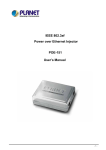
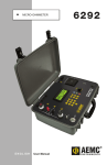
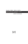
USER’S GUIDE
EO Modulator Driver and Source
Models 3363-A, 3363-B, and 3363-C
3635 Peterson Way • Santa Clara, CA 95054 • USA
Phone: (408) 919-1500
email: [email protected] • www.newport.com/newfocus
Please read the manual for safety information.
Warranty
New Focus, a Newport Company, guarantees its products to be free of
defects for one year from the date of shipment. This warranty is in lieu of all other
guarantees, expressed or implied, and does not cover incidental or consequential
loss. Refer to Newports Terms and Conditions of Sale for warranty coverage.
Information in this document is subject to change without notice.
Copyright 2007, Newport Corporation All rights reserved.
Document Number 330044 Rev. C
Contents
Operation
5
Introduction . . . . . . . . . . . . . . . . . . . . . . . . . . . . . . . . . . . . . . . . . . . 5
Overview of the Unit. . . . . . . . . . . . . . . . . . . . . . . . . . . . . . . . . . . . 6
Quick Start Instructions. . . . . . . . . . . . . . . . . . . . . . . . . . . . . . . . 10
Operation Details. . . . . . . . . . . . . . . . . . . . . . . . . . . . . . . . . . . . . . 11
Safety Notice . . . . . . . . . . . . . . . . . . . . . . . . . . . . . . . . . . . . . . . . . . 14
Characteristics
15
Specifications . . . . . . . . . . . . . . . . . . . . . . . . . . . . . . . . . . . . . . . . . 15
Performance Details . . . . . . . . . . . . . . . . . . . . . . . . . . . . . . . . . . . 16
Customer Service
23
Technical Support . . . . . . . . . . . . . . . . . . . . . . . . . . . . . . . . . . . . . 23
Service . . . . . . . . . . . . . . . . . . . . . . . . . . . . . . . . . . . . . . . . . . . . . . . . 23
Appendix I
25
Changing the Frequency of the Model 3363-B . . . . . . . . . . . 25
Appendix II
27
Changing the Frequency of the Model 3363-C . . . . . . . . . . . 27
EO Modulator Driver and Source
Contents • 3
4 • Contents
NEW FOCUS, Inc.
Operation
Introduction
The Model 3363 is a user-friendly EO modulator driver
which mates a frequency source and a power amplifier
with several handy user features in a compact package.
The unit runs from standard line voltage (US or
international). It is ideal for use with the New Focus
line of resonant modulators. (It can also be used with
our broadband EOMs as well, with lower resultant
modulation depth.)
The Model 3363-A contains a voltage-controlled
oscillator (VCO) as the frequency source, which is
available from 25 to 1000 MHz. The VCO source can
be tuned over a limited range via a convenient front
panel knob. In addition, the VCO frequency can be set
to track the resonance peak of the EOM; this locking
mode is selectable via a front panel toggle switch.
The Models 3363-B and 3363-C contain a highstability synthesized frequency source, available from
50 kHz to 2 GHz. The synthesized source is stabilized
to a crystal oscillator for excellent long- and shortterm stability. The output frequency is selected to
match your EOM at time of shipment, however, the
user may also adjust the frequency over a limited range
through the use of an external computer port.
A front-panel toggle switch allows the user to select
whether to use the internal frequency source or to use
an external source.
EO Modulator Driver and Source
Operation • 5
A matched output RF amplifier provides about 30 dBm
of power, enough to drive any of our resonant EO
modulators to provide approximately 3 radians of
phase modulation. The output modulation depth is
controlled through a convenient front-panel knob,
providing adjustment from no modulation to full
output power.
A reflected RF power monitor provides a DC signal
proportional to the voltage reflected back from the EO
modulator. For the VCO-based option, this feature
allows you to manually tune the frequency of the drive
box to the resonance of the modulator for maximum
modulation efficiency or monitor the frequencylocking circuit. For our fixed-frequency synthesizer
option, it can also be used to fine-tune the resonance
of our high-frequency EO modulators using the
integral tuning slug.
Other usability features include an RF output enable
switch to eliminate damage to the amplifier and/or
EOM while connecting and disconnecting the output,
an analog AM modulation input, and a TTL output
disable input.
Overview of the Unit
Shown in Figures 1 and 2 are the front and rear panel
of the unit. Figure 1 details the layout of “A” option of
the Model 3363 and Figure 2 details the layout of the
“B” and “C” options.
1. Power switch. Turns AC power to entire unit on
and off.
2. AC indicator. Lights when unit is powered.
3. RF amplifier enable. When depressed (and LED is lit)
the RF power amplifier is turned on. This switch
allows you to disable the RF amplifier when
connecting or disconnecting the EO modulator to
the RF output (9) without damaging the EOM or
6 • Operation
NEW FOCUS, Inc.
power amplifier. Note that when this button is off,
there may still be some signal leaking through; the
attenuation ranges from 16-30 dB depending upon
option and frequency chosen.
4. Internal Source/External Oscillator switch. When in the
up position (Int Source), the internal VCO or
synthesizer is used to produce the output. When
in the down position, an external frequency
source can be used.
5. External oscillator input (SMA female). When the
switch (4) is in the down (Ext Osc) position, this
input provides the oscillation source for the EOM
amplifier.
6. Frequency adjust knob, Option A only. Adjusts the
frequency of the VCO. Factory adjustment is
typically ±5% around the user-specified center
frequency. This is a one-turn potentiometer.
7. Lock/Free switch, option A only. When down, in the
“free” position, the frequency adjust knob (6) acts
normally to adjust the output frequency of the
unit. When up, in the “lock” position, the unit
tracks the resonance of the EOM.
8. Output Level knob. Adjusts the output power
delivered by the driver from approximately 3 dBm
on the low end to approximately 30 dBm on the
high end.
9. RF output. The high-level RF signal provided to the
modulator. This must be connected to the EOM or
a 50-ohm load when the RF enable (3) switch is on,
or damage may occur to the amplifier.
10. Reflected RF monitor. This provides a DC voltage
proportional to the RMS RF voltage reflected back
from the modulator. When the EOM resonance
and the frequency of the driver are equal, the
signal is a minimum. The exact value of the
minimum varies depending on drive level and
each individual modulator.
EO Modulator Driver and Source
Operation • 7
11. TTL Enable* Internal Source. The allows an external
TTL signal to perform the function of the Int/Ext
Source switch (4). When no external source is
connected to (5), a low level (nominal 0 V) on this
input allows the internal generator signal to pass
through; a high level (nominal 5 V) disconnects
the internal frequency source.
12. AM modulation input. This allows an external
analog voltage (0 to 5 V) to modulate the output
RF level. The output level knob (8) should be fully
counterclockwise (minimum output) when using
this input.
13. Option port, Option A. For the option A, VCO-based
models, this provides an auxiliary frequency
monitor with a fixed output of approximately
10 dBm.
14. EAC power input connector. AC power to the unit can
range from 90 to 250 VAC. The door above the
power connector contains the fuse. The fuse
installed in the unit will be appropriate for your
location’s voltage.
15. Frequency Lock indicator, Option B or C only. This LED
should remain lit when the unit is operating
properly; it indicates that the internal phaselocked loop circuit is locked to the internal
crystal source.
16. Option port, Option B or C only. For Option B, this is a
RS-232 DB-9 female connector. For Option C, this
is a parallel port DB-9 male connection. This port
allows the synthesizer frequency to be adjusted
from a computer.
8 • Operation
NEW FOCUS, Inc.
Figure 1: Front
and rear panel
of the 3363-A
4
6
8
9
3
2
5
1
7
10
11
13
EO Modulator Driver and Source
12
14
Operation • 9
Figure 2: Front
and rear panel
of the 3363-B
and 3363-C
15
16
Quick Start Instructions
The unit is ready-to-use straight out of the box. Check
that the power switch (1) is off and that the RF out on/
off switch (3) is “out”. Plug the line power cord into the
back of the unit (14) and into a wall socket. Connect
your EOM to the RF out port (9) using the supplied 48”
long SMA-to-SMA cable and secure both ends
properly (standard SMA torque is 9 in-lbs).
Turn power on to the unit by pressing the toggle (1). It
will take 2-3 seconds for the power supply and thus
front-panel indicator (2) to come on. Set the output
level knob (8) to the most counterclockwise position
for minimum output. Press the RF out on/off button
(3) to turn on the power amplifier. Turn up the level
knob (8) until you see modulation.
For the Model 3363-A model, you will likely need to
adjust the frequency knob to adjust the output
10 • Operation
NEW FOCUS, Inc.
frequency to be in resonance with the driver. By
attaching a common voltmeter to the reflected RF
monitor port (10), you can determine if you are at
resonance by adjusting the frequency until the signal
on the voltmeter is minimized. When you are near the
minimum, you can flip the lock/free switch (7) to the
“lock” position to have the VCO frequency track the
EOM resonance.
For the 3363-B and 3363-C models, the frequency is
fixed at the factory to the frequency specified at time of
order. By attaching a common voltmeter to the
reflected RF monitor port (10), you can monitor the
power reflected back by the EOM. Some of our highfrequency EOM models have a user-accessible slug that
allows you to tune the resonance of the EOM to match
and thus minimize the signal from the monitor port.
For an FM modulator, the easiest way to check for
modulation and measure modulation depth is to use
an optical spectrum analyzer. For an AM modulator,
one of our detectors is ideal for measuring
modulation. Using one of our DC-coupled receiver
models to observe the output signal from the EO
modulator is an ideal way to carefully measure
modulation depth.
Operation Details
Below in Figure 3 we show a simplified block diagram.
The top schematic shows the power supply
configuration common to all options, the middle
shows the Model 3363-A configuration, and the
bottom reflects the Models 3363-B and -C
configurations.
EO Modulator Driver and Source
Operation • 11
Figure 3:
Simplified
block diagram
of Model 3363
90-250
VAC
VCO
Fuse
RF
switch
AUX
Voltage
regulators
Power supply
Power
Voltage-ctrl’d
attenuator
OUT
Fixed
atte
Preamp
RF
power amp
Directional
coupler
RF out
to mod
CON
Locking
circuit
Option
(VCO aux)
RF
Detector
Lock /
Free
Frequency
Ext Osc
Input
Int
Source /
Ext Osc
TTL
Enable*
Internal
Source
AM
Modulation
Output
Level
RF Out
On/Off
Reflected
RF Monitor
Option A
Frequency Synthesizer
RF
switch
Voltage-ctrl’d
attenuator
Fixed
atte
Preamp
RF
power amp
VCO
Microcontroller
Option
(parallel or serial
port)
PLL
Directional
coupler
RF out
to mod
RF
Detector
Ext Osc
Input
Int
Source /
Ext Osc
TTL
Enable*
Internal
Source
AM
Modulation
Output
Level
RF Out
On/Off
Reflected
RF Monitor
Options B & C
In the Option A configuration, a voltage-controlled
oscillator (VCO) provides the sinusoidal frequency
source. A front-panel knob controls the frequency by
changing the applied voltage to the VCO. The main
VCO output is the input to an RF switch, and an
auxillary output is sent to the option port for
monitoring.
The RF switch provides the ability to use the internal
frequency source or an external user-provided source.
If the external oscillator is not connected, this switch
can be used to provide approximately 45 dB of
attenuation. The RF switch can also be actuated by an
external TTL input. When using this external input,
the switch is expected to be set to “Int Source” for
proper operation. The bandwidth of the TTL enable*
input is in excess of 1 MHz.
The RF output level and thus modulation depth is
provided by a voltage variable attenuator. The front
panel knob is normally used to adjust this level,
however an analog voltage from 0 to 5V on the AM
modulation input can duplicate this functionality.
12 • Operation
NEW FOCUS, Inc.
When using the external AM modulation, the output
level knob is expected to be fully counterclockwise
(minimum output). The bandwidth of this input is in
excess of 1 MHz.
A low-level preamplifier and an RF power amplifier
boost the signal to approximately 30 dB at maximum
output. The DC power to the RF power amplifier is
controlled by the RF out on/off switch (3), allowing
the RF amplifier to be disabled to change loads (EOMs).
This button effectively attenuates this output by
16-30 dB, depending upon the specific RF amplifier
model used.
A directional coupler, operated in reverse, samples any
power reflected back from the EOM. The reflected RF
signal from the coupler is sent to a power detector
which turns this RF into a DC voltage proportional to
the reflected RMS signal. An amplified version of this
signal is provided to the user.
When the lock/free switch is in the “lock” setting, this
signal is also used to adjust the VCO voltage to force
the frequency to track the resonance of the EOM. The
locking circuit adds a small dither (approximately 40
kHz) to the output frequency, which is used to track
the minimum of the EOM resonance. Note that some
models/frequencies of EOM (typically the 4001/4003
series) can have spurious resonances that are not at the
actual main resonance; these can be avoided by first
tuning the synthesizer to be very near the main
resonance before toggling the switch from free to lock.
The 3363-B and -C models, shown at the bottom of
Figure 3, replace the VCO-based source with a PLLbased synthesizer, and dispenses with the locking
circuit. The Option B synthesizer has a RS-232 serial
port interface and the Option C synthesizer has a
parallel port interface. The synthesizer frequency is
factory-set to the user’s desired frequency and use of
the computer port is optional only.
EO Modulator Driver and Source
Operation • 13
Safety Notice
The output RF must be disabled using the RF out on/
off switch (3) whenever the output (9) is connected or
disconnected or damage to the RF amplifier may
result!
There are no user-serviceable parts inside. Opening
the unit is not recommended and will violate the New
Focus warranty.
14 • Operation
NEW FOCUS, Inc.
Characteristics
Specifications
The specifications for all three models in a comparison format are shown in
the table below. The primary performance difference between the three units
is determined by the use of a VCO-based versus a synthesizer-based
frequency source.
All models are meant for indoor use, to be operated at altitudes upto 2000
meters and within 0-40°C temperature range. Maximum allowed non
condensed humidity is 95% with mains supply voltage fluctuation upto ±10%
of the nominal value. Rated degree of pollutions for all models is 2.
Model #
3363-A
3363-B
3363-C
Output RF power, max.
30 dBm typ.
30 dBm typ.
30 dBm typ.
Output power range
0-30 dBm
0-30 dBm
0-30 dBm
Max. mod with res. EOM
3 rad typ.
3 rad typ.
3 rad typ.
Ideal for EOM models
4001, 4003,
4103, 4421,
4423
4001, 4003,
4103
4001, 4003,
4103, 4421,
4423
Compatible with EOM
models
4002, 4004,
4104
4002, 4004,
4104
4002, 4004,
4104
Frequency range
25-1000 MHz
0.05-40 MHz,
in 0.001 Hz
steps
45-2000 MHz,
in 25-100 kHz
steps
Frequency stability
Tracks EOM
resonance
when locked
±1.5 ppm
±1 ppm
Frequency adjust range
±5% of center
(typical)
Fixed at factory*
Fixed at factory*
Frequency lock indicator
No
Yes
Yes
Output VSWR, max.
2: 1
2: 1
2: 1
EO Modulator Driver and Source
Characteristics • 15
Model #
3363-A
3363-B
3363-C
Output RF connection
SMA
SMA
SMA
Reflected RF monitor
16 V/Vrms
(typical)
16 V/Vrms
(typical)
16 V/Vrms
(typical)
Reflected RF connector
BNC
BNC
BNC
Ext. osc. input level
-10 dBm max.
-10 dBm max.
-10 dBm max.
Ext. osc. input conn.
SMA
SMA
SMA
Disable input
Std. TTL logic,
high to disable
Std. TTL logic,
high to disable
Std. TTL logic,
high to disable
Disable RF attenuation
45 dB typ.
45 dB typ.
45 dB typ.
Disable connector
BNC
BNC
BNC
AM modulation input
0-5 V (5V produces max RF
output)
0-5 V (5V produces max RF
output)
0-5 V (5V produces max RF
output)
AM modulation range
0-30 dBm
0-30 dBm
0-30 dBm
AM modulation conn.
BNC
BNC
BNC
Option connector
buffered VCO
mon., SMA
RS-232, DB-9
fem.
Parallel port,
DB-9 male
Power requirements
100-240VAC,
50/60 Hz,
1.0-0.5 A
100-240VAC,
50/60 Hz,
1.0-0.5 A
100-240VAC,
50/60 Hz,
1.0-0.5 A
Performan ce Details
In Figure 4 below, we show a typical plot of the output
voltage provided to the EOM versus the angle of the
output level knob (item 8 of Figure 1). The
substantially flat portions at either endof the knob
travel act to indicate the unit isproviding either
minimum or maximum available output. This curve
shows performance of a typical unit; the exact voltage
and angle will vary slightly from unit to unit
depending upon option and frequency chosen.
16 • Characteristic s
NEW FOCUS
20
18
Nominal Output (Vpp)
Figure 4:
Output of RF
Out in Vpp
versus Output
Level knob
angle
16
14
12
10
8
100 MHz
500 MHz
1 GHz
2 GHz
6
4
2
0
0
50
100
150
200
250
300
Knob angle (deg)
Figure 5 illustrates the typical response of the reflected
RF monitor port (item 10, Figure 1) for several
frequencies. The typical slope is 16 V of reflected port
signal for every RMS volt reflected back from the EOM.
Note that this port monitors power reflected back
from the load (typically an EOM), and not the forward
power transmitted to the load.
For reference, the coupler that captures the
backreflected power has 20 dB typical coupling to the
coupled port. The return loss, or S11, of our EOMs
varies by model and by frequency, but a typical value
of S11 is less than –25 dB on resonance. This value
rises to nearly 0 dB (highly reflective) far off resonance.
Note that it is very unlikely for the EOM and driver to
be this far off resonance, as the VCO tuning range of
the option A units is explicitly limited to ±5% of the
center frequency, and the option B and C units are
factory tuned to be at the EOM center frequency.
EO Modulator Driver and Source
Characteristics • 17
10
Reflected Power Monitor (Vdc)
Figure 5:
Typical
response of the
Reflected RF
Monitor port
9
8
7
6
50 kHz
100 kHz
1 MHz
10 MHz
100 MHz
1 GHz
2 GHz
5
4
3
2
1
0
0
0.1
0.2
0.3
0.4
0.5
0.6
0.7
0.8
Reflected Signal (Vrms)
Figure 6 shows the typical transfer function of the AM
modulation input (item 12, Figure 1). This input
mimics the front panel output level knob with a 0 to 5
volt input range. This analog input is designed to
operate with the output level knob set to minimum
(fully CCW).
20
18
Nominal Output (Vpp)
Figure 6:
Nominal RF Out
in Vpp versus
AM modulation
input voltage.
Output level
knob is turned
fully counter
clockwise
16
14
12
10
8
100 MHz
500 MHz
1 GHz
2 GHz
6
4
2
0
0
0.5
1
1.5
2
2.5
3
3.5
4
4.5
5
AM Modulation Voltage, Vmod (V)
Figure 7 shows the input return loss of the external
oscillator input (item 5, Figure 1) for the source
selector switch (item 4, Figure 1) in both positions. The
reflection is less than –9 dB when the external
oscillator input is enabled, but one should note that it
is slightly reflective when disabled.
18 • Characteristics
NEW FOCUS, Inc.
0
Ext Source Input S11 (dB)
Figure 7: Input
return loss of
external
oscillator input
port for both
internal and
external
oscillator
switch settings
-5
-10
-15
-20
Ext Osc
Int Source
-25
0
500
1000
1500
2000
2500
Frequency (MHz)
Figure 8 shows the output of the VCO aux output for
the 3363-A (“Option,” item 13 in Figure 1) on a
spectrum analyzer, with the system running free in the
top spectrum and locked in the bottom spectrum
(“Lock/Free” switch is item 7 in Figure 1). In both
figures, the horizontal scale is 50 kHz/division and the
vertical scale is 10 dB/division. The effect of the
locking circuit on the output spectrum is to broaden it
by approximately 40 kHz (the locking dither frequency
is approximately 900 Hz). Since the resonance of most
models of EOM is greater than 1MHz, the dither of the
locking circuit should have no direct effect on the
modulation depth.
EO Modulator Driver and Source
Characteristics • 19
Figure 8:
Frequency
spectrum from
3363-A with
locking circuit
disabled (left)
and enabled
(right). The
horizontal scale
is 50 kHz per
division, and
the vertical
scale is 10 dB
per division.
Figure 9 below shows the resonances of several models
of EOM, with frequencies ranging from 150 MHz to
1.8 GHz. These are typical responses, provided here to
show the typical range of quality factor (Q) and return
loss you might expect to see; results vary with
20 • Characteristics
NEW FOCUS, Inc.
modulator model and exact frequency. These data
were taken under small-signal conditions and at room
temperature. These plots are intended to help you
understand the change in backreflected power and
observed modulation depth as you tune either the
frequency of the 3363, or the resonant frequency of the
modulator itself.
As you observe the depth of modulation in your
system, you may observe the modulation depth
change over time, temperature, or drive level. Use of
the locking function on the 3363-A, or use of the
tuning slugs in the EOM itself, can be used to minimize
these variations. Practically speaking, due to heating of
the modulator crystal by the RF power incident upon
it, you may note that it takes a minute or two for the
modulation depth to stabilize as the temperature of
the crystal settles at that particular drive level.
-5
-5
Return Loss (dB)
Return Loss (dB)
Figure 9:
Return loss
plots near
resonance of
several EOM
models.
-15
-25
-35
4001 / 152 MHz
Q = 38
-45
145
150
155
-15
-25
-35
-45
440
160
4421 / 450 MHz
Q = 54
445
455
460
-5
Return Loss (dB)
Return Loss (dB)
-5
-15
-25
-35
-45
1.16
450
Frequency (GHz)
Frequency (GHz)
4421 / 1.2 GHz
Q = 226
1.165
1.17
1.175
Frequency (GHz)
EO Modulator Driver and Source
1.18
-15
-25
-35
-45
1.775
Special / 1.8 GHz
Q = 455
1.777
1.779
1.781
1.783
Frequency (GHz)
Characteristics • 21
22 • Characteristics
NEW FOCUS, Inc.
Customer Service
Technical Support
Information and advice about the operation of any
New Focus product is available from our technical
support engineers.
Engineers are on duty from 8:00-5:00 PST, Monday
through Friday (excluding holidays). For quickest
response, ask for “Technical Support” and have the
model number, option, frequency, and serial number
of your unit, which can be found on the back panel of
the unit.
Phone: (408) 919-1500
Fax: (408) 980-8883
Support is also available by email:
[email protected]
We typically respond to email within one business day.
Service
In the event that your unit malfunctions or becomes
damaged, please contact New Focus for a return
authorization number and instructions on shipping
the unit back for evaluation and repair. When calling
to request an RMA number, be sure you have the
option letter (A, B, C), frequency, and serial number
handy.
EO Modulator Driver and Source
Customer Service • 23
Fuse Replacement
Time Lag Fuse (Slo-Blo®) Fuse 239P Series,
250VAC, 1A
24 • Customer Service
NEW FOCUS, Inc.
Appendix I
Changing the Frequency of the Model 3363-B
The option port on the back of the Model 3363-B is a
standard RS-232 serial port. The frequency can be
changed using a couple of simple commands. This
appendix will describe how the user can change the
frequency if necessary. Note that changing the
frequency by a drastic amount from the factory setting
(more than 20% up or down) may change the output
power range that you see and is not recommended.
Connect the “Option” port of the unit to a standard
serial port cable, plugged into the serial port of your
computer. The cable is typically a DB-9 male to DB-9
female. Note that only GND, RX, and TX signal lines of
the RS-232 cable are used.
If you are running Windows 2000, launch
“Hyperterminal” on the computer. This is a standard
program on Windows 2000 and is accessible via “Start
> Programs > Accessories > Communications >
HyperTerminal.” You will need to create a new
connection with the following settings: 19 200 bit/s, 8
data bits, parity none, 1 stop bit, flow control none. If
you are running on another operating system, any
terminal server program that allows you to send and
receive characters over the serial port, set to the above
communications setting will work.
If you are running another operating system, any serial
port communications program with its parameters set
EO Modulator Driver and Source
Appendix I • 25
to 19200 bit/s, 8 data bits, no parity, 1 stop bit, and no
flow control will work fine.
Check that the connection is working and on the
status of the synthesizer by typing “QUE” into the
terminal screen. The unit should respond with a
hexidecimal string of characters, for example “0000
12309CE54000 2710 14050060 0A3A 02 20.” The
actual string will likely differ from this one based on
the settings for your unit.
You can change the frequency by typing “F0 ” (note the
space) followed by the frequency in megahertz. For
example, to set the output frequency to 27.34 MHz,
type “F0 27.34” followed by a return (the enter key).
The unit should reply “OK” on the terminal program.
Now type “S” followed by a return into the terminal
window. This step records the settings into the
EEPROM of the synthesizer. If you skip this step, the
frequency adjustment you made will be lost the next
time the unit is powered off. The unit should again
respond “OK” on the terminal program.
If desired, you may disconnect the serial cable and exit
HyperTerminal (or whatever terminal program you
are running) on the computer.
26 • Appendix I
NEW FOCUS, Inc.
Appendix II
Changing the Frequency of the Model 3363-C
The option port on the back of the Model 3363-C is a
standard parallel printer port. The frequency can be
changed using a small control panel computer
program available from New Focus. This appendix will
describe how the user can change the frequency if
necessary. Note that changing the frequency by a
drastic amount from the factory setting (more than
20% up or down) may change the output power range
that you see and is not recommended.
Connect the “Option” port of the unit to your
computer using a cable with a DB-9 female connector
to DB-25 parallel port connector. This cable is
available as a separate item from New Focus, contact
customer service to order this item.
Launch the control panel software on the computer. If
the software is not yet installed on the computer you
are using, please follow the instruction provided with
the cable or with the software when you download it
as instructed by customer service. The display should
come up without any error dialogues. If there are error
dialogues, the unit is not connected correctly, powered
up, or you may have to configure your parallel port
correctly as per the software installation instructions.
Type the desired user frequency in MHZ into the
“Frequency” box. Click “Store.” Note that making
changes to any other configuration parameters may
cause unstable or improper operation of the unit.
EO Modulator Driver and Source
Appendix II • 27
Once the computer indicates the new frequency was
successfully stored, you may disconnect the parallel
cable and exit the control panel on the computer.
28 • Appendix II
NEW FOCUS, Inc.