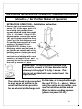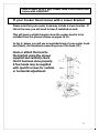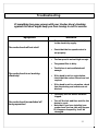
1
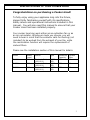
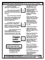
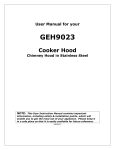
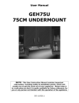
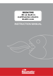
User Manual for your BH600&BH700&BH900 Cooker Hood Chimney Hood in Stainless Steel NOTE: This User Instruction Manual contains important information, including safety & installation points, which will enable you to get the most out of your appliance. Please keep it in a safe place so that it is easily available for future reference. 06/05/11 CONTENTS SPECIFICATIONS OF YOUR COOKER HOOD ………………………….3 IMPORTANT SAFETY INFORMATION……………………………….…4-5 CARING FOR THE ENVIRONMENT…………………………………………6 USING YOUR COOKER HOOD……………………………………………….7 MAINTAINING AND CLEANING YOUR COOKER HOOD ……. 8-12 Cleaning the anti-grease filter………………………... Changing the Light Bulb…………………………………. Changing & Installing Carbon Filter………………… 9-10 11 11-12 INSTALLATION INSTRUCTIONS ……………………….……...….12-20 Electrical Connection……………………………………… Installing the Cooker Hood……………………………… Attaching the Hood………………………………………… Fitting the Chimney……………………………………….. Extraction / Purifying version…………………………. Installing the Version with Lower Bracket………… 13 14-16 17 18-20 21 22 TROUBLESHOOTING ……………………………………………………….24 1 2 SPECIFICATIONS OF YOUR COOKER HOOD Congratulations on purchasing a Cooker Hood! To fully enjoy using your appliance long into the future, please firstly familiarise yourself with its specifications, safety advice and operational instructions included in this manual. You will also need this manual to ensure that your Cooker Hood has been installed properly. Your cooker hood can work either as an extraction fan or as an air recirculator. Whichever mode you choose, you will need to bear in mind that the extractor calls for ducting (not included) to be worked from the exhaust of your fan, while the recirculation function will require the replacement of carbon filters. Please see the installation section of this manual for details. Model BH600 Width (mm) 600 BH700 900 BH900 900 control light Electronic Button (AYD-001) Electronic Button (AYD-001) Electronic Button (AYD-001) 2*3W LED 2*3W LED 2*3W LED Extraction Capacity 750 Carbon filter S1 750 S1 750 S1 3 IMORTANT SAFETY INFORMATION: Please read this before installing o Any installation work must be carried out by a qualified electrician or competent person. o The hood must be installed in accordance with the installation instructions and all measurements followed. o If the cooker hood is installed for use above a gas appliance then the provision for ventilation must be in accordance with the all applicable regulations. o It is dangerous to alter the specifications or to modify this product in any way. Do not tamper with it or attempt to alter it in the attempt to customise it further. o When installing the hood, ensure that the following recommended distances are being observed between the cooker top and the bottom of the cooker hood: 9 9 9 Electric cookers: 700 mm Gas cookers: 700 mm Coal/ oil cookers: 800 mm * NOTE - DO NOT SET YOUR COOKER HOOD LESS THAN 700mm ABOVE YOUR COOKER! o When installed between adjoining wall cabinets, the cabinets must not overhang the hob. o The edges of the cooker hood are sharp – be mindful of this as you handle your appliance, especially during installation and cleaning. DO NOT CLEAN IN BEHIND THE GREASE FILTERS! o If the room where the cooker hood is to be used contains a fuel burning appliance such as a central heating boiler then its flue must be of the sealed or balanced flue type. o If other types of flue or appliances are fitted, ensure that there is an adequate supply of air in the room. o When the hood is being used in its extractor function, ensure that the ducting is fire retardant and that there are no bends sharper than 90 degrees as this will reduce the efficiency of the hood. o Ensure the ducting for the extractor function has the same diameter as the outlet hole all the way through. o Keep young children from using, playing with or tampering with the cooker hood. 4 o Older children and infirm persons should be supervised if they are using the cooker hood. o Please dispose of the packing material carefully – children are especially vulnerable to it. o Dirty oil is an even greater fire risk. o Always put lids on pots and pans when cooking on a gas cooker. o The manufacturer refuses to accept any responsibility for damages arising to the hood or its catching on fire from failure to observe fire safety advice in these instructions. o Remember that when in extraction mode, your cooker hood is removing air from your room. Ensure that proper ventilation measures are being observed. Note that it removes odours from your room, not steam. o Warning - Always ensure that the cooker hood has been disconnected from the power supply before carrying out any work on the hood, including replacing light bulbs. o Your cooker hood is for o If the supply cord is damaged it must be replaced by the manufacturer or service agent in order to avoid hazard. : Do not connect the ducting system of this appliance to any existing ventilation system which is being used for any other purpose. : Do not install above a cooker with a high level grill. : Never leave frying pans unattended during use as overheated fats and oils might catch fire. : Do not leave naked flames under the cooker hood. : Do not attempt to use the cooker hood if it is damaged in any way. Never attempt to use it without the grease filters fitted or if the filters are excessively greasy! : Never flambé cook under this cooker hood. o The lights on this appliance should only be used during operation of the cooker hood. They should not be left on permanently and used as a lighting source. domestic use only. 5 CARING FOR THE ENVIRONMENT THE MANUFACTURER DECLINES ALL RESPONSIBILITY IN THE EVENT OF FAILURE TO OBSERVE THE INSTRUCTIONS GIVEN HERE, FOR INSTALLATION, MAINTENANCE AND SUITABLE USE OF THE HOOD Note: Before discarding an old appliance, switch off and disconnect it from the power supply. Cut off and render any plug useless. Cut the cable off directly behind the appliance to prevent misuse. This should be undertaken by a competent person. CONFORMITY TO W.E.E.E. DIRECTIVE 6 USING YOUR COOKER HOOD To use your cooker hood: 1) Make sure it has been properly installed. 2) Find the CONTROL PANEL. It is located at the front of the canopy. You have a Pushbutton control panel that looks like the one pictured below. 3) The CONTROL PANEL’s buttons all perform separate functions. You will need to understand what these do before you attempt to use your cooker hood. * Note: The hood should be switched on at least as soon as you start cooking. 1. Turn on the power; the buzzer will buzz five times. The sound shows that the appliance is powered. 2. Push the low button, the indicating light 1 will turn on, the buzzer will buzz once, and the motor runs at low speed. Push it again and the motor will stop. 3. Push the middle button, the indicating light 2 will turn on, the buzzer will buzz once, and the motor runs at mid speed. Push it again and the motor will stop 4. Push the high button, the indicating light 3 will turn on, the buzzer will buzz once, and motor runs on high speed. Push it again and the motor will stop 5. Push the light button; the indicating light 4 will turn on, and the two lighting lamps will come on. Push it again and the lamps will turn off, with every push the buzzer will buzz one time. 7 MAINTAINING AND CLEANING YOUR COOKER HOOD PLEASE NOTE THAT YOUR COOKER HOOD CAN BE USED EITHER IN RECIRCULATION MODE OR IN EXTRACTION MODE. TO USE THE HOOD IN RECIRCULATION MODE, YOU WILL NEED TO FIT THE CARBON FILTERS (SEE PAGE 10-11) IMPORTANT!: Before cleaning, always ensure that you have switched your cooker hood OFF at the omni-polar switch, set at the wall from the cable:  Clean the external parts with mild liquid detergents on a damp cloth.  Never use abrasive powder, corrosive solvents or brushes.  Never insert pointed objects into the motor’s protective grid.  Only clean the control panel and filter grill with a damp cloth and delicate detergents.  Be sure to replace the carbon filters at the recommended intervals. Build up could cause a fire hazard.  Never take out the grease filters and attempt to clean the space above where they are set. Anti-Grease Grille  Your cooker hood includes an anti-grease grille which helps absorb vapour-suspended grease particles to protect your kitchen & furniture from greasy residues.  The metal grille may become flammable if it becomes saturated with greasy residue. To prevent this fire hazard, the grille should be cleaned regularly (depending on use) every 10-15 days and at least once a month in a dishwasher or in hot water with normal washing-up detergent. 8 Maintenance – Cleaning the Anti-grease Filters First remove the grille by pulling down on it. Undo the side catches. You can now clean the anti-grease filter grilles. 9 Soak them for about one hour in hot water with a grease-loosening detergent then rinse off thoroughly with hot water. 9 Repeat the process if needed. Refit the grease grille once it has dried. To clean the grease filter grilles in your dishwasher: 9 Place the grease filter grilles in the dishwasher. Select the most powerful washing programme and highest temperature. 9 Repeat the process, if necessary. 9 Refit the grease grilles when dry. 9 PLEASE NOTE: DISCOLOURATION OF THE GREASE FILTER CAN TAKE PLACE WHEN CLEANED IN A DISHWASHER, ETC. Do not worry about the slight discolouration of the grille – its performance won’t be affected. Let the filter grilles dry thoroughly before refitting them. 9 Maintenance – Changing the Light Bulb and Carbon Filter a) Changing the light bulb 9 Before changing the light bulb, ensure that the appliance is not live (i.e. ensure that you have switched it off at the wall switch). 9 Remove the metal anti-grease filters (see Figure 2 on the next page) and find the old bulb located in the light fixture up inside the exposed canopy. Change the halogen bulb using only olive-shaped spares with a G4 coupling, max. 20W. *PLEASE NOTE – Defective bulbs should be replaced immediately 9 Replace the metal anti-grease filters b) Installing / Changing the Carbon Filter 9 Your Baumatic Cooker Hood uses a pair of CARBON FILTERS to purify the air for the air recirculation function. 9 You will find that the filters will attach to both sides of the fan motor (please see figures on the next page). 9 The active carbon filters must be replaced regularly, at least once every three months, to allow normal operation. 9 Before starting to fit the carbon filter, turn the omni-polar switch off at the wall. 10 Changing the Carbon Filters 1) Press the handle of the metal grease filter towards the rear part of the unit until it is released from the front housing, and remove it by pressing downwards (Fig. 2 - above). 2) Remove the old carbon filters by twisting them anticlockwise until they unlatch from the sides of the motor. 3) Place the new carbon filters (which have two fixing tongues), turning clockwise so that the tongues latch onto the motor’s sides. (Fig. 3 - left). 4) Reposition the anti-grease metallic filter grilles. 11 INSTALLATION INSTRUCTIONS – Electrical Connection. Before installation and usage, read all the instructions and make sure that the voltage (V) and the frequency (Hz) indicated on the identification plate (found inside your Cooker Hood) and all the data inside the appliance are exactly the same as the voltage and frequency in your home. NOTE: The manufacturer declines all responsibility in the event of failure to observe all the accident-prevention regulations in force which are necessary for normal use and regular operation of the electric system. ______________________________________________ ELECTRICAL CONNECTION Yo Your cooker hood is fitted with a power cord & plug for connection to 10A power outlet . The power cable must be connected to the terminals marked L (live) and N (neutral) in the hood and fixed with a cable clamp. o o The cooker hood’s power cable must be fitted upstream from the electrical connection using an omni-polar switch with a contact distance of at least 3mm. NOTE: (UK only) WARNING – THIS APPLIANCE MUST BE EARTHED. It should only be connected by a competent person using fixed wiring via a DOUBLE POLE SWITCHED FUSED SPUR OUTLET. We recommend that the appliance is connected by a qualified electrician who will comply with all local regulations. The wires in the mains lead are coloured in accordance with the following U.K. code: Blue= Neutral, Brown = Live, Green/Yellow = Ground If you can only find two wires in the cable (blue and brown), neither must be connected to the Earth terminal! • As the colours of the wires in the appliance’s mains lead may not correspond with the coloured markings identifying the terminals in your spur box, please proceed as follows: 1) The BLUE WIRE must be connected to the terminal marked “N” (Neutral), or coloured Black 2) The BROWN WIRE must be connected to the terminal marked “L” (LIVE), or coloured Red 3) The Green/Yellow wire must be connected to the terminal marked “E” or (Earth) (Fig 7 – at left on next page / Wire diagram at right). 12 INSTALLATION INSTRUCTIONS – Installing your Cooker Hood PLEASE NOTE THAT YOU WILL HAVE TO DECIDE BEFORE INSTALLING YOUR COOKER HOOD THAT YOU CAN ADAPT IT AS AN EXTRACTION FAN. : The cooker hood must not be fitted above stoves with a radiant top plate. : We recommend that at least two people install this hood. NOTE: Your Cooker Hood should only be fitted on a wall. Do NOT position it any less than 700 mm (70 cm) above the hob. 1) Remove the metal anti-grease filters (See figure at right). 2) Position the hood against the wall and mark the position of the support holes that are to be drilled as shown in the figure on the next page. These support holes can be found on Fig. 4 on next page marked as ‘D’ with the anchoring holes marked as ‘E’ (Fig. 4 on next page). If your hood comes with an attached jig, use that as a guide to make the marks for the screw holes. 13 INSTALLATION INSTRUCTIONS – Attaching the Hood Rear view of your cooker hood. -------------------------------------------------------------------------3) Using a drill bit with an 8 mm diameter, make holes in the wall where you have marked these positions (see next page). 14 8 -------------------------------------------------------------------------------------------------------------------------------------------------------------------------------------------------------------------------------------------------- 4) Insert the expansion fixings (rawlplugs) in the holes and then screw the support screws halfway in (see below figure, at right). 5) Hook the hood onto the screws (see above figure) and fasten it onto the wall, tightening the support and anchoring screws the rest of the way in (next page, at top.) ------------------------------------------------------------------------------------------- 15 INSTALLATION INSTRUCTIONS – Attaching the Hood ------------------------------------------------------------------------------------------6) (EXTRACTION FUNCTION ONLY) Connect the coupling to the top of the cooker hood (see below). Then connect the discharge pipe to the coupling as shown below. Remember that your ducting will have to match the specifications shown in the notes on Extraction / Air Purifier (Recirculation) Modes on p.20. 16 INSTALLATION INSTRUCTIONS – Fitting the Chimney FITTING THE PIPE – Once your Cooker Hood has been installed, you can now fit the pipe. 1) Take the two casings ‘A’ and ‘B’: 2) Rest the bottom of the casing ‘A’ on the top of the hood, taking care to position the tabs of the casing correctly on the back of the hood as shown as part ‘X’ in Figure 4 at right. 3) Fix casing ‘A’ onto the hood using the two screws ‘K’ supplied in the bag of accessories (Figure 4 – at right). 4) Lift the mobile part ‘B’ until it reaches the ceiling, checking that it is perpendicular to the hood. 5) Mark the side measurement of the mobile casing ‘B’ and then lower it (see next page). 17 6) Take the fixing bracket ‘G’ (Fig. 4 – previous page), centre it with respect to the mark you previously made, keeping it in contact with the ceiling, and then mark the anchoring holes (‘H’). 7) Using a drill bit with an 8mm diameter, make two holes on the fixing marks you previously made (see below). 8 18 8) Insert the expansion fixings (rawlplugs) provided, put bracket ‘G’ (see Fig. 4 on previous page) in position and secure it with the screws provided. 9) Lift casing ‘B’ up to the ceiling and secure it to the bracket ‘G’, inserting the screws provided in the holes ‘M’ (Fig. 4 – previous page). 19 AIR PURIFIER (RECIRCULATION) OPERATION - Installation Instructions Extraction / Air Purifier Modes of Operation EXTRACTION OPERATION – Installation Instructions  Ensure that you have fitted the union (‘N’) to the upper part of the hood using the packaged two screws supplied inside the packing (Fig. 1 – on right). Using a 125 mm diameter pipe, connect the union (N) on the upper part of the hood (see Fig. 1) to the discharge outlet for cooking vapours with a crosssection of at least 150 cm².  PLEASE NOTE: If there is no discharge outlet and the hood is to be fitted to an outside wall of the building, make a hole in the wall that is large enough to fit a wind and rain-proof shutter with a cross section of at least 150 cm² and connect this to the outlet union of the unit by means of a pipe. Please note: For the extraction function, you will need to connect a 125 mm diameter outlet chimney to the spigot ‘N’ in fig. 1 above. This pipe is not provided with your cooker hood. See figure on left. The cooker hood can be converted to work as an air purifier in the event that there is no provision for an external air discharge duct. In this case, air is recycled through the vent ‘R’ (Fig. 1 – above). When using the unit as an air purifier, you need to install two active carbon filters to absorb cooking vapours (please see pages 10-11). 20 * Note on what to do if your Cooker Hood is the version that comes with a BRACKET. If your Cooker Hood comes with a Lower Bracket Please note that your cooker hood may include a lower bracket. If this is the case, you will need to have it installed as such. This will mean a slight change in how the cooker hood is to be installed from the process shown on pages 13-15. In Fig. 6, below, you will see an exploded view of your cooker hood and (inset), the bracketed connecting area of the hood (‘N’). Hook or attach the hood to the bracket using the screws supplied and carefully check that it has been done properly. A few hoods may be supplied with specific screws for vertical or horizontal adjustment. 21 Troubleshooting If something has gone wrong with your Cooker Hood, checking against this chart might keep you from having to call for service. Symptom The cooker hood will not start! The cooker hood is not working effectively! The cooker hood has switched off during operation! Solution • Check that the hood is connected to the electricity supply. • Check that the fan speed control is set properly. • The fan speed is not set high enough. • The grease filter is dirty. • The kitchen is not ventilated well enough. • If the hood is set for recirculation, check that the carbon filters have not expired. • If the hood is set for extraction, check that the ducting and outlets are not blocked. • The safety cut-out device has been tripped. • Turn off the hob and then wait for the device to reset. • Note that if you have installed your cooker hood too low, this will happen. If it happens frequently, it will be damaged. 22 My appliance isn’t working correctly IMPORTANT: If your appliance appears not to be operating correctly, then you should disconnect it from your mains supply and then contact Think Appliances Customer Care Department on telephone number 1 800 444 357 DO NOT ATTEMPT TO REPAIR THE APPLIANCE YOURSELF. Please note that if an engineer is asked to attend whilst the product is under guarantee and finds that the problem is not the result of an appliance fault, then you may be liable for the cost of the call out charge. The appliance must be accessible for the engineer to perform any necessary repair. If your appliance is installed in such a way that an engineer is concerned that damage will be caused to the appliance or your kitchen, then he will not complete a repair until you have arranged safe access to the appliance. As inaccessibility is not an appliance defect, warranty does not cover any costs incurred in arranging accessibility This includes situations where ladder or roofspace is necessary, appliances have been tiled in, sealed in with sealant, have wooden obstructions placed in front of the appliance, like plinth and any installation contrary to these instructions. Please refer to the conditions of guarantee that appear on the warranty card that you receive with the appliance. This guarantee is in addition to and does not diminish your statutory or legal rights. If you have any further questions please contact Think Appliances Pty Ltd: 23 SERVICE DEPARTMENT Phone: 1800 444 357 Fax: 1300 133 279 Email:[email protected] SALES DEPARTMENT Phone: 1300 132 824 Fax: 1300 660 188 Web: www.thinkappliances.com SPARE PARTS DEPARTMENT Phone: 1300 306 973 Fax: 1300 887 306 24