1
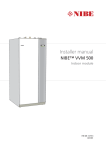
Installer manual NIBE™ F2026 LEK Air/water heat pump IHB GB 1244-2 031865 Table of Contents 1 Important information Safety information 2 Delivery and handling Transport and storage Assembly Supplied components Removing the covers 2 2 5 5 5 8 8 Soft-starter Compressor heater Collar heater Phase sequence control Start-up and inspection Readjusting, heating medium side Adjustment, charge flow 28 28 28 28 29 29 30 7 Control - Introduction 3 The heat pump design General Electrical cabinets 4 Pipe connections General Pipe coupling heating medium circuit Pressure drop, heating medium side Docking alternatives 5 Electrical connections General Connections Optional connections Connecting accessories 6 Commissioning and adjusting Preparations Filling and venting the heating medium system Balance temperature Stop temperature NIBE™ F2026 9 9 11 31 General Navigation Display explanation Control conditions 31 31 32 33 12 12 12 13 14 23 23 24 26 27 28 28 28 28 28 8 Control - Channels 35 Status channels Temperature channels Setting channels 35 35 35 9 Disturbances in comfort 37 Troubleshooting 37 10 Accessories 41 11 Technical data 42 Dimensions and setting-out coordinates Sound pressure levels Technical specifications Electrical circuit diagram Item register 42 43 44 46 51 Table of Contents | 1 1 Important information Safety information This manual describes installation and service procedures for implementation by specialists. Serial number The serial number can be found on the product's foot. This appliance is not intended for use by persons (including children) with reduced physical, sensory or mental capabilities, or lack of experience and knowledge, unless they have been given supervision or instruction concerning use of the appliance by a person responsible for their safety. Children should be supervised to ensure that they do not play with the appliance. 6HULDO QXPEHU Rights to make any design or technical modifications are reserved. Symbols LEK ©NIBE 2012. NOTE This symbol indicates danger to machine or person. Caution Always give the product's serial number when reporting a fault. Caution This symbol indicates important information about what you should observe when maintaining your installation. Country specific information Installer manual This installer manual must be left with the customer. TIP This symbol indicates tips on how to facilitate using the product. Marking F2026 is CE marked and fulfils IP24. The CE marking means that NIBE ensures that the product meets all regulations that are placed on it based on relevant EU directives. The CE mark is obligatory for most products sold in the EU, regardless where they are made. IP24 means that the product is secure against penetration by objects with a diameter larger than or equivalent to 12.5 mm and that the product is protected against drops from all directions. 2 Chapter 1 | Important information NIBE™ F2026 Inspection of the installation Current regulations require the heating installation to be inspected before it is commissioned. The inspection must be carried out by a suitably qualified person. Fill in the page for information about installation data in the User manual. ✔ Description Notes Signature Date Heating medium (page 12) System flushed System vented Particle filter Shut-off and drain valve Charge flow set Electricity (page 23) Fuses property Safety breaker Earth circuit-breaker Heating cable type/effect Fuse size, heating cable (F3) Communication cable connected Miscellaneous Condensation water pipe Insulation condensation water pipe, thickness (if KVR 10 is not used) NIBE™ F2026 Chapter 1 | Important information 3 Contact information AT KNV Energietechnik GmbH, Gahberggasse 11, 4861 Schörfling Tel: +43 (0)7662 8963-0 Fax: +43 (0)7662 8963-44 E-mail: [email protected] www.knv.at CH NIBE Wärmetechnik AG, Winterthurerstrasse 710, CH-8247 Flurlingen Tel: (52) 647 00 30 Fax: (52) 647 00 31 E-mail: [email protected] www.nibe.ch CZ Druzstevni zavody Drazice s.r.o, Drazice 69, CZ - 294 71 Benatky nad Jizerou Tel: +420 326 373 801 Fax: +420 326 373 803 E-mail: [email protected] www.nibe.cz DE NIBE Systemtechnik GmbH, Am Reiherpfahl 3, 29223 Celle Tel: 05141/7546-0 Fax: 05141/7546-99 E-mail: [email protected] www.nibe.de DK Vølund Varmeteknik A/S, Member of the Nibe Group, Brogårdsvej 7, 6920 Videbæk Tel: 97 17 20 33 Fax: 97 17 29 33 E-mail: [email protected] www.volundvt.dk FI NIBE Energy Systems OY, Juurakkotie 3, 01510 Vantaa Puh: 09-274 697 0 Fax: 09-274 697 40 E-mail: [email protected] www.nibe.fi FR AIT France, 10 rue des Moines, 67000 Haguenau Tel : 03 88 06 24 10 Fax : 03 88 06 90 15 E-mail: [email protected] www.nibe.fr GB NIBE Energy Systems Ltd, 3C Broom Business Park, Bridge Way, Chesterfield S41 9QG Tel: 0845 095 1200 Fax: 0845 095 1201 E-mail: [email protected] www.nibe.co.uk NL NIBE Energietechniek B.V., Postbus 2, NL-4797 ZG WILLEMSTAD (NB) Tel: 0168 477722 Fax: 0168 476998 E-mail: [email protected] www.nibenl.nl NO ABK AS, Brobekkveien 80, 0582 Oslo, Postadresse: Postboks 64 Vollebekk, 0516 Oslo Tel. sentralbord: +47 02320 E-mail: [email protected] www.nibeenergysystems.no PL NIBE-BIAWAR Sp. z o. o. Aleja Jana Pawła II 57, 15-703 BIAŁYSTOK Tel: 085 662 84 90 Fax: 085 662 84 14 E-mail: [email protected] www.biawar.com.pl RU © "EVAN" 17, per. Boynovskiy, Nizhny Novgorod Tel./fax +7 831 419 57 06 E-mail: [email protected] www.nibe-evan.ru SE NIBE AB Sweden, Box 14, Hannabadsvägen 5, SE-285 21 Markaryd Tel: +46-(0)433-73 000 Fax: +46-(0)433-73 190 E-mail: [email protected] www.nibe.se For countries not mention in this list, please contact Nibe Sweden or check www.nibe.eu for more information. 4 Chapter 1 | Important information NIBE™ F2026 2 Delivery and handling Transport and storage F2026 must be transported and stored vertically. Assembly ႑ Place F2026 outdoors on a solid level base that can take the weight, preferably a concrete foundation. If concrete slabs are used they must rest on asphalt or shingle. ႑ The concrete foundation or slabs must be positioned so that the lower edge of the evaporator is at the level of the average local snow depth, although a minimum of 300 mm. ႑ The F2026 should not be positioned next to sensitive walls, for example, next to a bedroom. ႑ Also ensure that the placement does not inconvenience the neighbours. ႑ F2026 must not be placed so that recirculation of the outdoor air can occur. This causes lower output and impaired efficiency. ႑ The evaporator should be sheltered from direct wind. Place F2026 protected from wind against the evaporator. ႑ Large amounts of condensation water as well as melt water from defrosting can be produced. Condensation water must be led off to a drain or similar (see page 6). ႑ Care must be exercised so that the heat pump is not scratched during installation. If there is a risk of snow slip from roof, a protective roof or cover must be erected to protect the heat pump, pipes and wiring. PLQ PP LEK LEK Do not place F2026 directly on the lawn or other non solid surface. NIBE™ F2026 Chapter 2 | Delivery and handling 5 Condensation water trough Recommended alternatives The condensation water trough is used to collect and lead away condensation water from the heat pump. Stone caisson NOTE It is important to the heat pump function that condensation water is led away and that the drain for the condensation water run off is not positioned so that it may cause damage to the house. NOTE Pipe with heating cable for draining the condensation water trough are not included. Frostfritt )URVW SURRI djup GHSWK NOTE To ensure this function the accessory KVR 10 should be used. LEK NOTE The electrical installation and wiring must be carried out under the supervision of an authorised electrician. If the house has a cellar the caisson must be positioned so that it does not affect the house. Otherwise the caisson can be positioned directly under the heat pump. The outlet of the condensation water pipe must be at frost free depth. Caution If none of the recommended alternatives is used good lead off of condensation water must be assured. ႑ The condensation water (up to 50 litres/day) collected in the trough should be routed by pipe to an appropriate drain, it is recommended that the shortest outdoor stretch possible is used. ႑ The section of the pipe that can be affected by frost must be heated by the heating cable to prevent freezing. ႑ Route the pipe downward from F2026. ႑ The outlet of the condensation water pipe must be at a depth that is frost free or alternatively indoors (with reservation for local ordinances and regulations). ႑ Use a water trap for installations where air circulation may occur in the condensation water pipe. ႑ The insulation must be tight against the bottom of the condensation water trough. Drain indoors :DWHU VHDO The condensation water can be routed to a drain indoors (with reservations for local rules and regulations). Route the pipe downward from F2026. The condensation water pipe must have a water trap to prevent air circulation in the pipe. 6 Chapter 2 | Delivery and handling NIBE™ F2026 Gutter drainage LEK :DWHU VHDO Frostfritt )URVW SURRI djup GHSWK The outlet of the condensation water pipe must be at frost free depth. Route the pipe downward from F2026. The condensation water pipe must have a water trap to prevent air circulation in the pipe. Installation area utrymme om 350 mm The distance between F2026 and the house wall must be at least 350 mm. Clearance in front of F2026 should be at least one metre. )UHH VSDFH EHKLQG Fritt )UHHutrymme VSDFH mm 400PP min. PLQ 3000 mm Fritt )UHHutrymme VSDFH mm 400 PP min. PLQ Fritt )UHH utrymme VSDFHframför LQ IURQW NIBE™ F2026 Chapter 2 | Delivery and handling 7 Supplied components LEK 2 flexible hoses (R25) with 4 seals Particle filterR25 Removing the covers 8 Chapter 2 | Delivery and handling NIBE™ F2026 3 The heat pump design General ;- %7 ;/ 41 +6 8% %3 50 (3 *4 *4 (% %7 LEK 8% 41 %7 (% +6 %3 %7 %7 ;/ (% (3 3) %7 ;/ %7 LEK ;/ 3) ;/ NIBE™ F2026 %7 :0 Chapter 3 | The heat pump design 9 Pipe connections XL 1 Connection, heating medium out of F2026, G1 (Ø28 mm) XL 2 Connection, heating medium in to F2026, G1 (Ø28 mm) XL 20 Service connection, high pressure XL 21 Service connection, low pressure XL 40 Connection, drip tray drain (Ø40 mm) Sensors etc. BP 1 High pressure pressostat BP 2 Low pressure pressostat BT 3 Temperature sensor, return BT 12 Temperature sensor, condenser supply line BT 14 Temperature sensor, hot gas BT 15 Temperature sensor, fluid pipe BT 16 Temperature sensor, evaporator BT 17 Temperature sensor, suction gas BT 28 Temperature sensor, ambient Electrical components EB 10 Compressor heater EB 11 Condensation water trough heater EB 13 Collar heater GQ 1 Fan Cooling components EP 1 Evaporator EP 2 Condenser GQ 10 Compressor HS 1 Drying filter QN 1 Expansion valve QN 2 4-way valve RM 1 Non-return valve Miscellaneous PF 1 Type plate PF 3 Serial number UB 1 Cable gland, incoming supply UB 3 Cable gland, sensor WM 5 Condensation water trough XJ 5 Connections sensors Designations in component locations according to standard IEC 81346-1 and 81346-2. 10 Chapter 3 | The heat pump design NIBE™ F2026 Electrical cabinets $$ $$6 $$6) $$6 $$6 $$6 ;- ; ; $$ $$ ) ; ; & %$ )& ; 8% LE K )% ; Electrical components AA 6 Relay card with power supply unit AA 10 Soft-starter AA 21 Control card with display S1 Plus button S2 Minus button S3 Enter button S4 Reset button SF 3 Display contrast BA 1 C2 F3 FB 1 FC 1 X1 X2 X3 X5 X6 X7 Miscellaneous UB 2 Cable gland, incoming supply XJ 5 Connections sensors Designations in component locations according to standard IEC 81346-1 and 81346-2. Phase sequence monitor (3-phase) Operating condenser, fan Fuse for external heating cable (250 mA), max 45 W. Automatic protection (10 A/30 mA) Motor fuse Terminal block, incoming supply Terminal block, external control voltage Terminal block, charge pump, external heating cable Terminal block, thermostat, communication, blocking compressor Terminal block, additional heat, downtime, common alarm Terminal block, 4-way valve NIBE™ F2026 Chapter 3 | The heat pump design 11 4 Pipe connections General Pipe installation must be carried out in accordance with current norms and directives. ure into consideration. Alternatively, the heat pump is connected to an intermediate circuit with a heat exchanger, pump and water with anti-freeze (does not apply to docking with VVM 300/VVM 500). F2026 can only operate up to a return temperature of about 50 °C and an outgoing temperature of about 58 °C from the heat pump. F2026 is not equipped with external shut off valves on the water side; these must be installed to facilitate any future servicing. The return temperature is limited by the return line sensor. Water volumes When docking with F2026 a minimum available system volume of at least 20 litres per kW output on the heat pump is recommended. NOTE The pipe work must be flushed before the heat pump is connected, so that any contaminants do not damage the components. Pipe coupling heating medium circuit ႑ F2026 can be connected directly to the heating system see the section "Docking" or according to one of the system solutions that can be downloaded from the website www.nibe.eu. ႑ The heat pump must be vented by the upper connection (XL1, HM-out) using the venting nipple on the enclosed flexible hose. ႑ Install the supplied particle filter (HQ1) before the inlet, i.e. the lower connection (XL2, HM-in) on F2026. ႑ All outdoor pipes must be thermally insulated with at least 19mm thick pipe insulation. ႑ Install shutoff (QM40) and drain (QM1) valves so that F2026 can be emptied in the event of prolonged power failures. ႑ The supplied flexible hoses act as vibration dampers. The flexible hoses are fitted so a slight bend is created, thus acting as vibration damping. Charge pump NOTE The charge pump must be operational, even if F2026 is not running, to prevent damage due to freezing. The charge pump can also be controlled directly from F2026, terminal (X3), which takes the outdoor temperat12 Chapter 4 | Pipe connections NIBE™ F2026 Pressure drop, heating medium side F2026 -6, 8, 10 3UHVVXUH GURS Tryckfall N3D kPa 9 6 kW 8, 10 kW 8 7 6 5 4 3 2 1 )ORZ Flöde 0 0 0,10 0,20 0,30 0,40 0,50 0,60 0,70 l/sOV +HDW LQVXODWLRQ L ;/ ;/ NIBE™ F2026 Chapter 4 | Pipe connections 13 Docking alternatives F2026 can be installed in several different ways. The requisite safety equipment must be installed in accordance with current regulations for all docked options. See www.nibe.eu for more docking options. When docking with F2026 a minimum available system volume of at least 20 litres per kW output on the heat pump is recommended. Explanation AA25 AA4 BT1 BT2 BT3 BT6 BT25 BT50 QN10 QN11 CL11 BT51 EP5 GP9 HQ3 QN19 RN10 EB15 AA25 BT1 BT2 BT6 BT24 BT52 CM1 EB20 FL1 FL2 FL10 FQ1 GP10 KA2 QM4 QN11 EB100 BT31 BT34 FL10 GP12 HQ1 QM1 14 Control unit (Indoor module) (SMO 05, SMO10, Control centre) Display unit Outside sensor Temperature sensor, heating medium, flow Temperature sensor, heating medium, return Temperature sensor, hot water, charging Supply line sensor, external Room sensor Reversing valve, Hot water/Heating medium Mixing valve, addition Pool kit Temperature sensor, pool Exchanger, pool Pool, pump Particle filter Three way valve, pool Trim valve Indoor module (EVP 270, VVM 300, VVM 500) Control box Outside sensor Temperature sensor, heating medium, flow Temperature sensor, hot water, charging Docking sensor Boiler sensor Expansion vessel, closed, heating medium Immersion heater Safety valve, water heater Safety valve, boiler Safety valve, heat pump Mixer valve, hot water Circulation pump, heating Auxiliary relay Drain valve Mixing valve, addition Heat pump (F2026) Room thermostat (RT 10) Thermostat, charging Safety valve, heat pump Charge pump Particle filter Drain valve, heating medium Chapter 4 | Pipe connections QM40 RN10 RM1 EB101 FL10 GP12 HQ1 QM1 QM40 QM41 RM1 RN10 EB102 FL10 GP12 HQ1 QM1 QM40 RM1 RN10 EM1 BT52 CM1 FL2 KA1 EP21 BT2 BT3 GP10 QN25 Miscellaneous AA25KA10 AA25KA11 BT1 BT31 CM1 CP1 CP10 Shut-off valve Trim valve Non-return valve Heat pump (F2026) Safety valve, heat pump Charge pump Particle filter Drain valve, heating medium Shut-off valve Shut-off valve Non-return valve Trim valve Heat pump (F2026) Safety valve, heat pump Charge pump Particle filter Drain valve, heating medium Shut-off valve Non-return valve Trim valve Oil, gas, pellets or wood boiler Temperature sensor, boiler Expansion vessel, closed, heating medium Safety valve, heating medium Auxiliary relay Climate system 2 Temperature sensor, heating medium, flow Temperature sensors, heating medium return Circulation pump, heating medium Shunt valve Auxiliary relay/Contactor Auxiliary relay/Contactor Outside sensor Room thermostat (RT 10) Expansion vessel closed, heating medium Buffer vessel (UKV) Accumulator tank with hot water heating (VPA/VPAS/VPB) CP10-EB20 Immersion heater CP11 Buffer vessel (UKV) EB1 Electric heater / Electric boiler EB1-BP5 Pressure gauge EB1-QM40 Shut-off valve EB1-QM60 Venting valve EB1-QN25 Shunt valve EB1-RM1 Non-return valve FL1 Safety valve, hot water FL2 Safety valve, heating medium FL11 Safety valve, heat pump FQ1 Mixer valve, hot water NIBE™ F2026 GP10 KA3 QM31 QM32 QN10 QN26 RM3 RN10 RN11 Circulation pump, heating medium Auxiliary relay Shut-off valve, heating medium, supply Shut off valve, heating medium, return Reversing valve, hot water/heating medium Overflow valve Non-return valve Trim valve Trim valve NIBE™ F2026 Chapter 4 | Pipe connections 15 F2026 docked with VVM 300 (floating condensing) -EB15 -EB15-BT1 -EB101 -FL10 -EB101 -QM41 -HQ1 -QM40 -QM1 ) 990 NOTE When cable routing, sensor cables and communication cables must be separated (min 20 cm) from high voltage cables to prevent interference. NOTE Check that you have a VVM 300 with version 1.30 or newer. If you have an earlier model of VVM 300 the control card must be replaced in the indoor module. The modular cable is then connected directly to the outdoor module control card. F2026 (slave) can be connected to VVM 300 (master). F2026 is then controlled by VVM 300 and works with floating condensing to the heating system and prioritises hot water charging in VVM 300. If F2026 cannot meet the heating requirement, additional heat is shunted in from VVM 300. If the ambient temperature drops below the set stop temperature, VVM 300 engages and takes over heating. 16 Chapter 4 | Pipe connections NIBE™ F2026 F2026 docked with VVM 500 (floating condensing) -EB15-FL2 -EB15 -CM1 -EB15 -EB15-BT1 -EB101 -FL10 -EB101 -QM41 -RM1 -HQ1 -QM40 -QM1 ) F20XX 990 VVM 500 F2026 (slave) can be connected to VVM 500 (master). F2026 is then controlled by VVM 500 and works with floating condensing to the heating system and prioritises hot water charging in VVM 500. If F2026 cannot supply the whole heating requirement the additional heat is supplied from VVM 500. If the ambient temperature drops below the set stop temperature, VVM 500 engages and takes over heating. NIBE™ F2026 Chapter 4 | Pipe connections 17 F2026 docked to the electric/oil-fired/pellet boiler together with SMO 05 and water heater (floating condensing) -FL2 -AA25 -KA10 -CM1 -EB1 -QM31 -GP10 -AA25 -BT25 -CP11 -QN26 -AA25 -AA25-AA4 -QM32 -AA25-BT1 -AA25 -BT7 -AA25-BT50 -CP10 -FL11 -QN10 -EB101 -AA25 -BT6 -FL10 -EB101 -QM1 -QM40 -RM1 -GP12 -HQ1 -AA25 -KA11 -RN11 -RN10 -CP10 -EB20 ) SMO 05 (master) is a simple control module that together with F2026 (slave), a hot water heater and an extra heat source create a complete installation. F2026 works with floating condensing against the heating system and prioritises hot water charging via the three way valve. NOTE When cable routing, sensor cables and communication cables must be separated (min 20 cm) from high voltage cables to prevent interference. 18 Chapter 4 | Pipe connections NIBE™ F2026 F2026 docked to the electric/oil-fired/pellet boiler together with SMO 10 and water heater (floating condensing) -AA25 SMO 10 Oljepanna alternativt elpanna med shunt -KA3 -EM1 -FL2 -CM1 -CP1 -EM1 -AA25-QN11 -AA25 -GP10 -EP21 -QN25 -BT2 -BT52 -GP10 -AA25-BT2 -RN10 -RM1 -BT3 -AA25-BT3 -KA1 -CL11 -EP5 -CL11 POOL -HQ3 -RN10 -QN19 -GP9 -BT51 -EB102 -FL10 -EB102 -QM40 -RM1 -RN10 -QM1 -GP12 -EB15 -HQ1 -EB15 -AA25 -QN10 -EB101 -FL10 -AA25-BT1 -RM1 -EB101 -AA25 -BT6 -FL10 -QM40 -EB20 -QM1 -HQ1 -KA2 -GP12 SMO 10 (master) controls one or up to nine F2026 (slaves), additional heater, circulation pumps, shunts, etc. F2026 works with floating condensing against the heating system and prioritises hot water charging via the three way valve. If F2026 cannot meet the heating requirement, the additional heat is started and is shunted in. NIBE™ F2026 -RN10 When additional heat is engaged, hot water is heated using the immersion heater in the hot water heater. NOTE When cable routing, sensor cables and communication cables must be separated (min 20 cm) from high voltage cables to prevent interference. Chapter 4 | Pipe connections 19 F2026 docked with EVC 13 (floating condensing) -EB100-BT31 -EB1 -EB1 -BT1 -EB100 -FL10 -EB100 -QM40 -HQ1 -RN10 -QM1 ) F2026 is controlled by a room thermostat and works with floating condensing on the return from the heating system. If F2026 cannot meet the heating requirement the additional heat is shunted in using the existing control equipment from EVC 13. Additional heat can be blocked above the set ambient temperature by means of the automatic control system in F2026. The heating medium also circulates through F2026 during the set stop temperature. Hot water production only takes place using the existing hot water heater. The right curve is selected in EVC 13 so that F2026 is not disturbed. This option requires accessory RT 10. NOTE When cable routing, sensor cables and communication cables must be separated (min 20 cm) from high voltage cables to prevent interference. 20 Chapter 4 | Pipe connections NIBE™ F2026 F2026 docked to an electric/oil boiler (floating condensing) -EB100 -BT31 -EB1 -EB1 -EB1-QM60 -BP5 -FL2 P -EB1-QM40 -EB 1 -EB1 -GP10 -RM1 -EB1-CM1 -EB1-QN25 -EB1 -EB100 ([WHUQDO RU H[LVWLQJ Extern alt FRQWURO HTXLSPHQW r befintlig utrustning -FL10 -EB100 -EB100 -AA25 -QM40 -HQ1 -GP12 -RN10 -QM1 ) F2026 is controlled by a room thermostat and works with floating condensing on the return from the heating system. If F2026 cannot meet the heating requirement the additional heat is shunted in using the existing control equipment. Additional heat can be blocked above the set balance temperature by means of the automatic control system in F2026. In other cases the heat pump does not collaborate with the electric/oil fired boiler in the optimum way. Hot water production only takes place using the existing electric/oil boiler. This option requires accessory RT 10. NIBE™ F2026 Chapter 4 | Pipe connections 21 F2026 docked with wood fired boiler and hot water heater (fixed condensing) -BT1 -AA25 -EB15 ([WHUQDO Extern RU alt.H[LVWLQJ FRQWURO HTXLSPHQW befintlig regler- utrustning. -EB100 -EM1 -RM1 -EB100 -FL10 -EB100 -BT34 -QM40 -HQ1 -RN10 -QM1 -GP12 ) F2026 charges the water heater/accumulator tank (EB15). When the firewood boiler is in use, the heat pump and immersion heater are disconnected when the temperature rises on the thermostat (BT34) and start again when the temperature drops. Too high temperature in the tank can generate alarm in the outdoor module and should be restricted to 60 °C. Self-circulation through the heat pump is prevented by the check valve (RM1). 22 Chapter 4 | Pipe connections NIBE™ F2026 5 Electrical connections General ႑ A heat pump must not be connected without the permission of the electricity supplier and must be connected under the supervision of a qualified electrician. ႑ If a miniature circuit breaker is used this should have motor characteristic "C" (compressor operation). For MCB size see "Technical Specifications". ႑ F2026 does not include an omnipolar circuit breaker on the incoming power supply. The heat pump’s supply cable must be connected to a circuit-breaker with at least a 3 mm breaking gap. When the building is equipped with an earth-fault breaker the heat pump should be equipped with a separate one. Incoming supply must be 400 V 3NAC 50Hz via distribution boards with fuses. ႑ If an insulation test is to be carried out in the building, disconnect the heat pump. ႑ Connect control signal cable for thermostat to terminal (X5). Cable type: unscreened LiYY, screened LiYCY. Cable area, at least 0.22with cable lengths less than 50m. ႑ Alternatively the relevant screened signal cable is connected from terminal block (X5) to SMO 05/SMO 10/NIBE indoor module. ႑ The routing of cables for heavy current should be made out through the cable glands on the heat pump's left-hand side, seen from the front (UB1) and signal cables from the rear (UB3). ႑ Charge pump for F2026 can be connected to separate supply or to terminal block (X3). NOTE! If F2026 is not powered and the charge pump is connected to the terminal block (X3) there is a risk of freezing ႑ A common alarm can be connected to terminal (X6). ) ; $$ ; LE K ; ; ; )% %$ )& NOTE Electrical installation and service must be carried out under the supervision of a qualified electrician. Electrical installation and wiring must be carried out in accordance with the stipulations in force. NOTE The external control must be taken into consideration when connecting. NIBE™ F2026 Chapter 5 | Electrical connections 23 Connections NOTE To prevent interference, unscreened communication and/or sensor to external connections cables must not be laid closer than 20 cm to high voltage cables when cable routing. LEK Power connection ,QFRPLQJ VXSSO\ Incoming supply cable is supplied and factory connected to the terminal block -X1. Approx. 1.8 m cable is accessible outside the heat pump. 24 Chapter 5 | Electrical connections NIBE™ F2026 Connecting external control voltage NOTE continually. This function applies on the condition that F2026 is powered. 0LQXWHV SHU PLQXWHV Mark up any electrical cabinets with warnings for external voltage. 35 30 25 When connecting external control voltage with separate earth-fault breaker disconnect the cables between terminal blockX1:N and X2:N and between terminal block X1:L1 and X2:L1 (as illustrated). Operating voltage (1x230V+N+PE) is connected to X2:N and X2:L1 (as illustrated). 20 15 10 5 0 5 4 3 2 1 0 -1 -2 -3 -4 -5 -6 -7 -8 -9 -10 -11 -12 -13 -14 -15 -16 -17 -18 -19 -20 -21 -22 -23 -24 -25 7HPSHUDWXUH ; PE :LULQJ NOTE There is a risk of freezing when the charge pump is connected to the terminal block - X3 and F2026 is not powered. N L1 L2 ([WHUQDO ) 1 2 L3 3 5 6 N 4 N L PE 7 L1 *3 ; ; External heating cable (KVR 10) At connection of external control voltage you must connect a switch (for tariff control) to connection X5:1 and X5:5 (compressor blocking) to prevent MP alarm. ([WHUQDO ) 1 F2026 is equipped with a terminal block for an external heating cable (EB14, not supplied). The connection is fused with 250 mA (F3, 15 W/m). If another cable is to be used the fuse must be replaced by one of a suitable size (see table). 2 3 &RPSUHVVRU EORFNLQJ 4 Total output (W) Fuse (F3) NIBE Part no. 1 3 6 15 45 90 T100mA/250V T250mA/250V T500mA/250V 718085 518900* 718086 5 Length (m) 6 ; Charge pump To let F2026 control the charge pump (GP12), connect it to the terminal block X3:4(N), 5(L) and 7(PE).. Pump activity is dependent on the status of F2026, heating/hot water requirement and the ambient temperature. Pump exercising is handled by F2026. * Factory installed. External heating cable (EB14) is connected to terminal block X3:1 and 4 as illustrated: With potential free connection of the circulation pump you replace the bracket with separate voltage supply for X3:6(L). Anti-freeze function At temperatures below +2 °C, the charge pump runs periodically, and at temperatures below -20 °C it runs NIBE™ F2026 Chapter 5 | Electrical connections 25 ([WHUQDO Optional connections ) 1 2 ([WHUQDO KHDW FDEOH 3 NOTE The following pages about thermostats, additional heat, common alarms and downtime, do not apply when F2026 is controlled by SMO 05/SMO 10 or NIBE indoor module. 4 5 (% 6 7 ) ; Thermostat control NOTE The pipe must be able to withstand the heat from the heating cable. To ensure this function the accessory KVR 10 should be used. You can use a basic thermostat or a closing potential-free contact to switch the compressor on and off. This thermostat should be of the breaking type (NC) when the set temperature has been reached. The contactor should be potential free. Connect the thermostat to terminal block X5:2 and 5 as illustrated below. Cable routing ([WHUQDO ) 1 2 3 7KHUPRVWDW 4 5 6 The following image displays the recommended cable routing from the electrical cabinet to the condensation water trough in F2026. The transfer from electrical cable to heating cable must occur after the lead-in to the condensation water trough. The distance between the electrical cabinet and the lead-in to the condensation water trough is approx.1930 mm. ; Additional heat / Downtime F2026 is equipped with a potential free contactor intended for additional heat. Max 250V 2A. The setting of the ambient temperature (balance temperature) when the additional relay is activated is made on channel A5, see the section "Control - Channel description". External additional heat is connected via the additional relay terminal block X6:1 to 3. Conditions for connecting additional heat: ႑ The ambient temperature should be lower than the set balance temperature (channel A5). ႑ The compressor must have been operating for the minimum period that can be set in channel A6. Defrosting is included in this time. /HDG LQ LEK +HDWLQJ FDEOH Ambient temperature sensor An ambient temperature sensor (BT28) is located on the underside of F2026. If the ambient temperature drops down to a level below the set value, stop temperature (downtime), in channel A7 compressor operations are blocked and all heating must take place using the external additional heat via the downtime relay, terminal block X6:4 (6). This function is also activated when F2026 is deenergized. If the ambient temperature exceeds 35 °C compressor operation is blocked and the downtime relay is activated. The connection to the additional relay is made as illustrated below. 26 Chapter 5 | Electrical connections NIBE™ F2026 ([WHUQDO NC 2 COM 3 NO 4 NC 5 'RZQWLPH Stillestånd 1 $GGLWLRQDO KHDW Tillsatsvärme Communication ) NO ,QGRRU Innemodul PRGXOH ) F2026 6 COM F2026 can communicate with NIBE indoor modules, by connecting the indoor module to the terminal block X5:3, X5:4, X5:5 as illustrated: ; -X5 ; 1 2 Max load across the relay contactors is 250V 2A. 3 During operations without the need of the additional heat or downtime the relay contactors are closed between NO and COM. A+ 4 B- 5 GND 6 Additional heat and downtime are acquired between NC and COM. The contactors are drawn in the deenergized state. Additional and downtime relays are activated during normal operating conditions for F2026. Both relays are deactivated in the event of operating disruptions. Example of addition connection Basic electrical circuit diagram for connection of auxiliary relays for additional heat and downtime. For connection of indoor module, see relevant manual on www.nibe.eu. External indication of main alarm F2026 is equipped with a contact for external indication of common alarms. The function becomes active with all types of existing alarms. Max load on the relay contact is250V 2A. The connection for external indication of common alarms is made to terminal block X6:7 to 9 as illustrated below: NO NC &20 O/C ([WHUQDO ) 6 COM NO 9 NC 8 Summalarm &RPPRQ DODUP 7 12 – 230V ; $X[LOLDU\ FRQWDFWRU Hjälpkontaktor QRW VXSSOLHG NIBE™ F2026 Connecting accessories Instructions for connecting accessories are in the installation instructions provided for the respective accessory. See page 41 for the list of the accessories that can be used with F2026. Chapter 5 | Electrical connections 27 6 Commissioning and adjusting Preparations Compressor heater ႑ Before commissioning, check that the heating circuit is filled and well vented. ႑ Check the pipe system for leaks. F2026 is equipped with a compressor heater that heats the compressor before start-up and when the compressor is cold. NOTE Filling and venting the heating medium system The compressor heater must have been connected for 6 – 8 hours before the first start, see the section "Start-up and inspection". 1. The heating medium system is filled with water to the required pressure. 2. Vent the system using the venting nipple on the enclosed flexible hose and possibly the circulation pump. Collar heater F2026 is equipped with a collar heater that heats the fan collar when necessary (not activated on delivery). 9HQWLQJ QLSSOH NOTE The collar heater is only required in certain cases where the ambient temperature is too low for a long period. Phase sequence control %$ Balance temperature The balance temperature is the outdoor temperature when the heat pump’s stated output is equal to the building’s output requirement. This means that the heat pump covers the whole building’s output requirement down to this temperature. Set the balance temperature, additional heat, in channel A5. Stop temperature When the stop temperature (channel A7) is set between -7 and -20 C the flow temperature is limited linearly from -7 C / 58 °C to -20 °C / 50 °C (see diagram on page 45). If the ambient temperature is below the set value for stop temperature heating must occur using the additional heat. LE K The phase sequence sensor (BA1) starts as soon as the power supply is connected to the heat pump. Check the phase sequence as shown below. ႑ Red LED is lit at correct phase sequence ႑ If there is a fault in the phase sequence, the heat pump receives an alarm 07 in channel S1 and the LED flashes. NOTE Check the phase sequence when starting! Soft-starter F2026 is equipped with soft-start (AA10) that limits the inrush current for the compressor. 28 Chapter 6 | Commissioning and adjusting NIBE™ F2026 Start-up and inspection ) ; $$ ; 1. Communication cable or thermostat, terminal block (X5) must not be connected. 2. Turn the isolator switch on. 3. Ensure that the F2026 is connected to the power source. 4. Check that the automatic protection (FB1) is on. 5. Check that the motor circuit-breaker (FC1) is on. 6. Check that the LED on phase sequence sensor (BA1) lights red. 7. The compressor heater (EB10) must have been operational for at least 6 – 8 hours before the compressor start can be initiated. This is done by switching on the control voltage and disconnecting the communications cable or thermostat. LE K ; ; ; )% %$ )& 8. The display on the control card (AA21) shows C0/CC F0 H1/H3 depending on the ambient temperature. During this period the compressor is heated to increase the service life. 9. The communication cable or external thermostat is connected after 6 – 8 hours. See section Thermostat control” electrical connection chapter. 10. Restart any NIBE SMO 05/SMO 10 or NIBE indoor module. See information in relevant manual on www.nibe.eu Readjusting, heating medium side Air is initially released from the hot water and venting may be necessary. If bubbling sounds can be heard from the heat pump, the circulation pump and radiators the entire system will require further venting. When the system is stable (correct pressure and all air eliminated) the automatic heating control system can be set as required. 11. Once the connection is made, the compressor starts after approx. 20 minutes if needed. 12. Adjust the charge flow according to the diagram, see the section "Adjustment, charge flow" 13. Adjust the menu settings if necessary. 14. Fill in the commissioning report in the user manual. 15. Remove the protective film from the cover on F2026. NOTE The external control must be taken into consideration when connecting. NIBE™ F2026 Chapter 6 | Commissioning and adjusting 29 Adjustment, charge flow ambient temperature is above 28 °C the charge flow should be in the lower region. Adjusting the temperature difference (ΔT) between the flow temperature and the return temperature is best done during hot water charging or at high load. The diagrams show the heat pump with a high fan speed, at low fan speeds ΔT will be 0.5 to 1 degrees lower (does not apply to F2026-6 kW, which only has one fan speed). This is most easily done using the temperatures measured in channel T2 (supply temperature) minus channel T3 1 and 4 flow temperature. 35 °C 2 and 5 flow temperature. 45 °C (return temperature). This temperature difference (ΔT) is adjusted using the circulation pump and control valve. Adjustment is performed with stable operation about 5 minutes after start, or about 5 minutes after defrosting at cold ambient temperatures. 3 and 6 flow temperature. 55 °C Quoted outputs refer to compressor, fan and control at nominal heating medium flow. During operation that requires defrosting the relationship between input and output is reduced by about 10%. The temperature difference must be within the grey area in accordance with the diagram below (+1- 2 K). If the F2026 Charge flow F2026-6 3KDVH FXUUHQW $ 6SHFLILHG RXWSXW N: Injustering av laddflöde för EVP 270 Adjustment of charge flow 18,0 T (°C) Δ 12 max max 17,0 1 2 3 16,0 10 15,0 14,0 nom nom 13,0 min min. 8 12,0 5DWHG RXWSXW 11,0 10,0 6 9,0 8,0 7,0 6 5 4 4 6,0 5,0 3KDVH FXUUHQW 2 4,0 3,0 2,0 -20 -15 -10 -5 0 5 10 15 20 25 30 0 35 (°C) -20 Outdoor temperature -10 -5 0 5 10 15 20 25 30 2XWGRRU WHPSHUDWXUH F2026-8 F2026-10 3KDVH FXUUHQW $ 6SHFLILHG RXWSXW N: 3KDVH FXUUHQW $ 6SHFLILHG RXWSXW N: 15 1 2 3 14 13 18 1 2 3 17 16 12 11 14 5DWHG RXWSXW 10 8 6 5 4 7 6 5 5DWHG RXWSXW 12 9 10 8 6 5 4 6 3KDVH FXUUHQW 4 3KDVH FXUUHQW 4 3 2 2 -20 -15 -10 -5 0 5 10 15 20 25 30 2XWGRRU WHPSHUDWXUH 30 -15 Chapter 6 | Commissioning and adjusting -20 -15 -10 -5 0 5 10 15 20 25 30 2XWGRRU WHPSHUDWXUH NIBE™ F2026 7 Control - Introduction General Navigation F2026 is equipped with an internal electronic control that handles those functions that are necessary for operation of the heat pump, for example defrosting, stop at max/min temperature, connection of the compressor heater as well as enabling the heater for the condensation watering trough and monitoring of pressure switches. The temperatures, number of starts and the operating time can also be read. The integrated controller is set during installation and can be used during a service. 34 Under normal operating conditions the home owner does not need to have access to the controller. Plus button F2026 has an integrated return line sensor that limits the return temperature. The plus button (S1) is used to browse through the channel system (forwards) or raise the value of the selected parameter. F2026 can also be switched on/off via signals from other control equipment or a thermostat. If F2026 is controlled from the indoor module, VVM eller SMO (accessory), the control is described in the instructions supplied. F2026 communicates with the indoor module which means that settings and measurement values from F2026 can be adjusted and read off in the indoor module. See the section “Control” – “Channel description” Minus button The minus button (S2) is used to browse through the channel system (backwards) or lower the value of the selected parameter. See the section “Control” – “Channel description” Enter button The Enter button (S3) is used to activate and confirm value changes. See the section “Control” – “Channel description” To modify a value, first press the Enter button to activate modification mode, the value flashes. Adjust the value as required using the Plus button or Minus button. Holding the Plus button or Minus button in for about 3 seconds speeds up the change in value. Then confirm using the Enter button. The value will stop flashing. The instructions are divided into three parts: status, temperatures and adjustable values. Quick movement between the different types is carried out by pressing the enter button when STATUS, TEMP. or ADJUST. are displayed. NIBE™ F2026 Chapter 7 | Control - Introduction 31 Display explanation C0 F0 S1 H0 H1 Compressor heater on H2 Condensation water trough heater on H3 Compressor heater on 01 Condensation water trough heater on Compressor: C Shows the present compressor status. C0 Compressor off, circulation pump off C Flashes when the compressor wants to start but is prevented by the time conditions or high return temperature. C1 Compressor on, circulation pump on CC Compressor off, circulation pump on CD Defrosting in progress H4 Collar heater on H5 Compressor heater on Collar heater on H6 Condensation water trough heater on Collar heater on H7 Compressor heater on Condensation water trough heater on Collar heater on Channel: S1 Shows the current channel. Change channels using the Plus button or the Minus button. Fan: F The fan has two speeds, high or low (does not apply to F2026-6 kW that only have one fan speed). The fan is controlled by the ambient temperature. The lower speed is used when the ambient temperature is too high to limit the output. The fan does not run during defrosting. At an ambient temperature lower than the temperature in the table below the fan speed is changed to high. Type Ambient temperature (°C) 8 kW 11 10 kW 13 F0 Fan off F1 Fan on, low speed F2 Fan on, high speed Value: 01 Shows the current value. Increase/decrease value using the plus button respective minus button. Heater: H The compressor heater is always active when the compressor is switched off. The condensation water trough heater is connected during defrosting when the ambient temperature falls below or is equal to 2.5 °C. If the collar heater is permitted (channel A14), it activates every third defrosting, when the ambient temperature lies below 2 °C. H0 Compressor heater off Condensation water trough heater off Collar heater off 32 Chapter 7 | Control - Introduction NIBE™ F2026 A = Set temperature for cold outdoor air + 2.1 °C. Control conditions 1. The ambient temperature (channel T1) drops below the set temperature in channel A7 (B). The heat pump stops and both the relays are activated. Control conditions, cold outdoor air ႑ ႑ ႑ ႑ ႑ When the ambient air temperature (channel T1) drops below the set temperature in channel A7 the heat pump stops and indicates 03 in channel S1. Both the additional relay and the downtime relay are then activated at the same time. 2. The ambient temperature is 2.1 °C) above the set temperature in channel A7 (A). A time counter starts from 0. 3. The ambient temperature falls below A. The timer is reset and stopped. If the ambient temperature sensor registers a temperature that is at least 2.1 °C higher than the set temperature in channel A7, a time counter starts. 4. The ambient temperature returns to above A. The time counter starts again (from 0). 5. The time counter has counted to 45 minutes. Both When the time counter has reached 45 minutes, both the additional relay and downtime relay deactivate to obtain a more comfortable temperature for the compressor to start at. relays are deactivated. 6. The time counter has counted to 60 minutes. The compressor is permitted to start again. When a further 15 minutes have passed, the compressor is permitted to start and the additional relay activates a few seconds later. However, the downtime relay is deactivated. NOTE If the ambient temperature at any point during the total 60 minutes falls below channel A7 + 2.1 °C the counter is reset. It does not start counting again unless the temperature is sufficiently high once again. If VVM 300/SMO 10 is connected it is not the value in menu 4.0 but the value of the ambient temperature in menu 5.9 which is used. It is heat pump’s ambient temperature sensor that applies. B = Set temperature for cold outdoor air (channel A7). 2XWGRRU WHPSHUDWXUH Utelufttemperatur utelufttemp. A B 1 NIBE™ F2026 2 3 4 5 6 Chapter 7 | Control - Introduction 33 Control conditions defrosting ႑ A time counter counts up every minute if the compressor is running and the temperature of the evaporator sensor (channel T7) falls below the setting in channel A9 ႑ If the time counter has reached the setting in channel A8, defrosting starts. ႑ If the collar heater is activated in channel A14, the ambient temperature is less than or equivalent to 2 °C and the compressor is running the collar heater starts at every third defrosting. The collar heater prevents the build up of ice on the fan collar. ႑ If "defrosting fan" is activated in channel A15, depending on the evaporator temperature and if the collar heater is not operating defrosting fan starts at defrosting. Defrosting fan prevents ice build up on the fan blades and the front fan grille. Defrosting occurs as follows: 1. The four way valve shifts to defrosting 2. The fan stops and the compressor continues to run. 3. When defrosting is complete the four way valve shifts back to heating mode and after 30 seconds the fan starts. 4. The ambient temperature sensor is locked and the high return temperature alarm is blocked for two minutes after defrosting. There are five possible reasons for defrosting to finish: 1. The temperature of the evaporator sensor has reached the set temperature in channel A10 (normal stop). 2. Defrosting has run longer than set in channel A11. Can be due to insufficient energy in the heat source and/or that the sensor on the evaporator is poorly positioned and gives too low a temperature (in the event of cold outdoor air). 3. The temperature on the return sensor falls below 10 °C. 4. The high-pressure switch deploys during defrosting. This is indicated as alarm 10 in channel S1 and the compressor is stopped. After two minutes the compressor starts again (if the pressure has fallen), otherwise there is a constant high pressure alarm (alarm 06). 5. The temperature on the flow temperature sensor falls below 4 °C. 34 Chapter 7 | Control - Introduction NIBE™ F2026 8 Control - Channels Status channels Status These channels show the status and statistics. Channel S1 Shows the operating status of F2026. Value 01 Normal operation. 02 Defrosting is run. 03 Cold outdoor air temperature. 04 High return temperature. 05 Low pressure switch (BP2) has tripped. 06 High pressure switch (BP1) has tripped. 07 Motor fuse (FC1) and/or phase sequence sensor(BA1) has deployed. 08 Sensor alarm. One of the temperature sensors is defective. 09 Communication error (only when SMO 05/SMO 10/NIBE innemodul is connected). 10 High pressure switch (BP1) has tripped during defrosting (resets automatically) 11 Not used. 12 Flow and return line sensors fitted incorrectly. 13 Hot outdoor air. Appears when the ambient temperature exceeds 35 °C. 14 High flow temperature. 15 Defrosting interrupted. Appears if defrosting is unsuccessful 3 times in a row. 16 Short operations times. Appears if operation time has been shorter than 2 minutes 3 times in a row. 17 Hot gas alarm. Appears when the hot gas exceeds 120 °C. The alarm resets automatically when the temperature falls below 60 °C. If the alarm is activated 3 times within 240 minutes it becomes continuous. S2 Value Shows the compressor status. 00 Compressor off. 01 Compressor on. XX Compressor blocked due to an alarm nn Compressor start in nn minutes. S3 Shows the number of compressor starts, accumulatively. S4 Shows the compressor's operating time in hours, accumulatively. S5 Shows the operating hours for connected additional heat, accumulatively. S6 Shows whether any additions are activated S7 Alarm input status (HP, LP and BA1), 1 indicates the input is OK. S7 1 / 1 / 1 S10 Software version number. Temperature channels Temp. These channels show the current temperatures. Channel T1 Measured temperature on the ambient temperature sensor (BT28). T2 Measured temperature on the flow temperature sensor (BT12). T3 Measured temperature on the return line sensor (BT3). T4 Measured temperature on the suction gas sensor (BT17). T5 Measured temperature on the hot gas sensor (BT14). T6 Measured temperature on the liquid line sensor (BT15). T7 Measured temperature on the evaporator sensor (BT16). Setting channels Adjust. All setting are made on these channels. Channel A1 Address for communication with SMO 05/SMO 10/NIBE indoor module (master). When connecting to SMO 05/NIBE indoor module this channel should be on 1. When connecting to SMO 10 this must be selected so that each F2026 (slave) in the system receives a unique address (1 – 9) for communication with SMO 10. For example 3 x F2026 in the same system are allocated the addresses 1, 2 and 3. The F2026 that produces hot water should be set to 1. A2 Max return temperature. When the return temperature reaches the set value the compressor stops. The value is adjustable between 25 and 50 °C. Factory setting 48 °C. With SMO/NIBE indoor module connected this menu cannot be changed, it is locked at 50 °C. Active input indicated by 1. Deactivated input indicated by 0. NIBE™ F2026 Chapter 8 | Control - Channels 35 A3 Connection difference return temperature. After the compressor is stopped for a high return temperature, the return temperature must drop by the set value in order to permit the compressor to start. The value is adjustable between 0 and 10 °C. Factory setting is 4 °C. A4 A5 A6 A7 A8 A15 Activating the "defrosting fan" function. Change the value 0 till 1 and confirm using the Enter button. With SMO/NIBE indoor module connected this menu cannot be changed, it is locked at 2 °C. Minimum time period in minutes between compressor starts. The value is adjustable between 20 and 60 minutes. Factory setting 20 minutes. Balance temperature, the set ambient temperature when the additional relay can be activated from channel A6 without affecting compressor operations. Additional heat relay is activated first after the set time on channel A6. The value is adjustable between -15 and +10 °C. Factory setting is 0 °C. Continuous operating time with the compressor before additional heat is permitted. The value is adjustable between 1 and 120 minutes. Factory setting 120 minutes. Stop temperature, the set ambient temperature value when the downtime relay is activated, F2026 stops. When the stop temperature is set between 0 and -20 °C the flow temperature is limited linearly to -7 °C / 58 °C to -20 °C / 50 °C (see diagram on page 45). Factory setting is -20 °C. Minimum running time, heat production before new defrosting is permitted. The value is adjustable between 10 and 90 minutes. Factory setting according to the table below. Type Minutes 6 kW 8 kW 10 kW 60 50 45 A9 Start temperature for permitted defrosting (evaporator sensor). The value is adjustable between 1 and 5 °C. Factory setting 1 °C. A10 Stop temperature for defrosting (evaporator sensor). The value is adjustable between 10 and 40 °C. Factory setting 10 °C. A11 Longest permitted defrosting time. The value is adjustable between 5 and 12 minutes. Factory setting 7 minutes. NOTE In the event of any defrosting problems, the value in channel A11 can be increased to relieve the problem. A12 Manual activation of defrosting procedure. Change the value 0 to 1 and confirm using the Enter button. A13 Restore factory default settings. Change the value 0 to 1 and confirm using the Enter button. A14 Activating the collar heater function. Change the value 0 till 1 and confirm using the Enter button. 36 Chapter 8 | Control - Channels NIBE™ F2026 9 Disturbances in comfort ႑ Set the thermostats to max in as many rooms as possible. Troubleshooting NOTE Work behind covers secured by screws may only be carried out by, or under the supervision of, a qualified installation engineer. ႑ External switch for changing the room heating activated. ႑ Check any external switches. ႑ Incorrect settings in the NIBE indoor module. ႑ See the manual for the indoor module. NOTE As F2026 can be connected to a large number of external units, these should also be checked. High room temperature ႑ External switch for changing the room heating activated. ႑ Check any external switches. NOTE In the event of action to rectify malfunctions that require work within screwed hatches the incoming electricity must isolated at the safety switch. ႑ ႑ See the manual for the indoor module. F2026 is not operational ႑ ႑ ႑ ႑ That the heat pump is running or that the supply cable to F2026 is connected. ႑ Group and main fuses of the accommodation. ႑ The property's earth circuit breaker. ႑ The heat pump's motor circuit breaker (FC1). ႑ The heat pump's automatic protection (FB1). ႑ ႑ Ambient temperature is hotter than 35 °C. Indicated as 13 in channel S1. ႑ Wait until the ambient temperature is colder than 33 °C. ႑ Time conditions do not permit start. ႑ Wait until the set conditions have run out. (If C flashes in the display the start conditions have been given.) ႑ Large hot water consumption. Motor fuse (FC1) and/or phase sequence sensor(BA1) has deployed (MS alarm). Indicated as 07 in channel S1. ႑ Wait until the hot water has heated up. ႑ Check the fuses. Incorrect settings in the NIBE indoor module. ႑ Check the phase sequence on incoming electricity supply. ႑ See the manual for the indoor module. Low room temperature ႑ Tripped low pressure pressostat. Indicated as 05 in channel S1. ႑ Ensure that the air flow is not blocked. ႑ Low hot water temperature or a lack of hot water This part of the fault-tracing chapter only applies if the heat pump is docked to the hot water heater. Tripped high pressure pressostat. Indicated as 06 in channel S1. ႑ Check that the system has been vented correctly. Check the fuses. Check that the particle filter is not blocked. Check that the circulation pump is rotating. Basic actions ႑ Cold outdoor air. Indicated as 03 in channel S1. ႑ Wait until the ambient temperature is 2 °C higher than the heat pump’s set stop value. The following tips can be used to rectify comfort disruption: Start by checking the following possible fault sources: Fuses have tripped. ႑ Replace the fuse or reset the MCB. ႑ NOTE Alarms are reset on indoor module. External control equipment has not given the start signal. ႑ Check the settings on the control equipment. NOTE In the event of any defrosting problems, the value in channel A11 can be increased to relieve the problem. Incorrect settings in the NIBE indoor module. Closed thermostats in several rooms. NIBE™ F2026 ႑ Flow and return line sensors fitted incorrectly. Indicated as 12 in channel S1. ႑ Check the pipe installation. Chapter 9 | Disturbances in comfort 37 ႑ The heat pump will not defrost. ႑ Check the temperature on the return line sensor (channel T3). If it is below 10 °C the heat pump will not defrost. Check the temperature on the evaporator sensor (channel T7). If it is higher than the set Start temperature, defrosting (channel A9) during compressor operation the heat pump will not defrost. Sensor placement %3 %3 LP %7 %7 %7 %7 %7 HP Check the temperature on the return line sensor (BT3). If it is below 10 °C the heat pump will not defrost. ႑ High flow temperature (T2). Indicated as 14 in channel S1. ႑ Check the charge flow and the particle filter which may be partially clogged. ႑ 34 High return temperature (T3). Indicated as 04 in channel S1. 34 ႑ Check the charge flow and the note the compressor’s limitations at low ambient temperatures. ႑ Unsuccessful defrosting. Indicated as 15 in channel S1. %7 %7 ႑ Check the charge flow. ႑ Short operations times Indicated as 16 in channel S1. ႑ Check the connection difference for the thermostat. Check the start temperature hot water in any NIBE indoor module. Check the charge flow and the particle filter which may be partially clogged. ႑ Hot gas temperature exceeds 120 °C. Indicated as 17 in channel S1. ႑ Contact refrigeration technician. Ice build up in the fan collar NOTE BP1 BP2 BT3 BT12 BT14 BT15 BT16 BT17 BT28 High pressure pressostat Low pressure pressostat Temperature sensor, heating medium return line Temperature sensor, condenser supply line Temperature sensor, hot gas Temperature sensor, fluid pipe Temperature sensor, evaporator Temperature sensor, suction gas Ambient temperature sensor Only applies in certain areas. ႑ Collar heater (channel A14) not activated. ႑ Activate the collar heater in channel A14. Ice build up on the fan blades and front grille NOTE Only applies in certain areas. ႑ "Defrosting fan" (channel A15) not activated. ႑ Activate "defrosting fan" in channel A15. 38 Chapter 9 | Disturbances in comfort NIBE™ F2026 Data for return line temperature sensor (BT3), condensor supply (BT12) and fluid pipe (BT15) Temperature (°C) -40 -35 -30 -25 -20 -15 -10 -5 0 5 10 15 20 25 30 35 40 45 50 55 60 65 70 75 80 85 90 95 100 NIBE™ F2026 Resistance (kOhm) 351.0 251.6 182.5 133.8 99.22 74.32 56.20 42.89 33.02 25.61 20.02 15.77 12.51 10.00 8.045 6.514 5.306 4.348 3.583 2.968 2.467 2.068 1.739 1.469 1.246 1.061 0.908 0.779 0.672 Voltage (VDC) 3.256 3.240 3.218 3.189 3.150 3.105 3.047 2.976 2.889 2.789 2.673 2.541 2.399 2.245 2.083 1.916 1.752 1.587 1.426 1.278 1.136 1.007 0.891 0.785 0.691 0.607 0.533 0.469 0.414 Data for hot gas sensor (BT14) Temperature (°C) Resistance (kOhm) Voltage (V) 40 45 50 55 60 65 70 75 80 85 90 95 100 105 110 115 120 125 130 135 140 118.7 96.13 78.30 64.11 52.76 43.64 36.26 30.27 25.38 21.37 18.07 15.33 13.06 11.17 9.59 8.26 7.13 6.18 5.37 4.69 4.10 4.81 4.77 4.72 4.66 4.59 4.51 4.43 4.33 4.22 4.10 3.97 3.83 3.68 3.52 3.36 3.19 3.01 2.84 2.67 2.50 2.33 Chapter 9 | Disturbances in comfort 39 Data for evaporator sensor (BT16), ambient temperature sensor (BT28) and suction gas sensor (BT17) Temperature (°C) -50 -45 -40 -35 -30 -25 -20 -15 -10 -5 0 5 10 15 20 25 30 35 40 45 50 55 60 65 70 75 80 85 90 95 100 40 Resistance (kOhm) 77.58 57.69 43.34 32.87 25.17 19.43 15.13 11.88 9.392 7.481 6.000 4.844 3.935 3.217 2.644 2.186 1.817 1.518 1.274 1.075 0.911 0.775 0.662 0.568 0.490 0.4233 0.367 0.320 0.280 0.245 0.216 Chapter 9 | Disturbances in comfort Voltage (VDC) 4.71 4.62 4.51 4.37 4.21 4.03 3.82 3.58 3.33 3.07 2.80 2.54 2.28 2.03 1.80 1.59 1.39 1.22 1.07 0.93 0.81 0.71 0.62 0.54 0.47 0.41 0.36 0.32 0.28 0.25 0.22 NIBE™ F2026 10 Accessories AB I II III AB -2 I II 0 I II AB +2 VVM 300 LEK LEK LE K VVM 300 VPA SMO 10 KVR 10 Indoor module. Double-jacketed hot water cylinder Control box Condensation water pipes, different lengths. Part no. 069 010 Part no. 089 638 VPA 300/200 Part No. 088 710 KVR 10-10, 1 m Part no. 067 171 VPA 450/300 Part No. 088 660 KVR 10-30, 2.5 m Part no. 067 172 KVR 10-60, 5 m Part no. 067 173 K AJ 30 °C LE 10 20 25 LE K 15 HR 10 RT 10 VT 10 VST 11 Auxiliary relay Room thermostat Heating thermostat Hot water control Part no. 089 423 Part no. 418 366 Part no. 418 801 Shuttle valve, Cu-pipe Ø28 Max recommended charge power, 15 kW Part no. 089 152 NIBE™ F2026 Chapter 10 | Accessories 41 11 Technical data Dimensions and setting-out coordinates 130 315 370 XL2 30-50 440 70 200 1045 465 XL1 125 350 1075 1175 365 520 75 130 Ø 40 utrymme om 350 mm 1200 )UHH VSDFH EHKLQG Fritt )UHHutrymme VSDFH mm 400PP min. PLQ 3000 mm Fritt )UHHutrymme VSDFH mm 400 PP min. PLQ Fritt )UHH utrymme VSDFHframför LQ IURQW 42 Chapter 11 | Technical data NIBE™ F2026 Sound pressure levels F2026 is usually placed next to a house wall, which gives a directed sound distribution that should be considered. Accordingly, you should always attempt when positioning to choose the side that faces the least sound sensitive neighbouring area. The sound pressure levels are further affected by walls, bricks, differences in ground level, etc and should therefore only be seen as guide values. F2026 works with low fan speed or high fan speed depending on the ambient temperature (does not apply to F2026 - 6 kW which only has one fan speed). R LEK 2m 6m 10 m F2026-6 F2026-8 F2026-10 Sound power level LW(A) 57 57/62 57/62 Sound pressure level at 2 m. Fan low/high* dB(A) 43 43/48 43/48 Sound pressure level at 6 m. Fan low/high* dB(A) 33.5 33.5/38.5 33.5/38.5 Sound pressure level at 10 m. Fan low/high* dB(A) 29 29/34 29/34 *Free space. NIBE™ F2026 Chapter 11 | Technical data 43 Technical specifications 3x400V 6 8 10 Output data at nominal flows 1) 15/55 Delivered / Supplied power / COP 7/35 Delivered / Supplied power / COP 7/55 Delivered / Supplied power / COP 2/35 Delivered / Supplied power / COP 2/45 Delivered / Supplied power / COP 2/55 Delivered / Supplied power / COP -7/35 Delivered / Supplied power / COP -7/45 Delivered / Supplied power / COP -7/55 Delivered / Supplied power / COP -15/35 Delivered / Supplied power / COP -15/45 Delivered / Supplied power / COP kW/kW/kW/kW/kW/kW/kW/kW/kW/kW/kW/kW/kW/kW/kW/kW/kW/kW/kW/kW/kW/kW/- 7.35/2.30/3.20 6.78/1.53/4.43 6.07/2.26/2.69 5.90/1.55/3.81 5.56/1.81/3.07 5.23/2.26/2.31 4.34/1.56/2.78 4.25/1.77/2.40 3.94/2.16/1.82 3.60/1.47/2.44 3.50/1.94/1.80 9.80/3.04/3.22 9.30/2.23/4.17 8.32/2.96/2.81 8.11/2.14/3.78 7.68/2.47/3.11 7.11/2.86/2.48 6.02/1.98/3.04 5.81/2.30/2.52 5.55/2.66/2.09 4.88/1.87/2.61 4.22/2.47/1.71 11.52/3.58/3.22 10.90/2.65/4.11 9.89/3.47/2.85 9.40/2.54/3.71 9.08/2.92/3.11 8.70/3.37/2.58 7.31/2.37/3.08 7.05/2.74/2.58 6.70/3.12/2.15 5.77/2.22/2.60 5.69/3.01/1.89 Output data according to EN 14511 7/35 Delivered / Supplied power / COPEN14511 kW/kW/- 6.24/1.50/4.16 8.57/2.21/3.87 9.80/2.62/3.74 7/45 Delivered / Supplied power / COPEN14511 kW/kW/- 5.95/1.75/3.40 8.30/2.55/3.26 9.60/2.99/3.21 Electrical data Rated voltage Max operating current, heat pump Arms 4.9 400V 3NAC 50 Hz 6.4 7.6 Max operating current, compressor Arms 4.3 5.9 6.9 Starting current Arms 18 24 27 Max permitted impedance at connection point 2) Nominal output fan (low/high) Fuse - - - W Arms 70 10 90/130 10 90/130 10 Refrigerant circuit Type of refrigerant Type of compressor Volume Cut-out value pressostat HP Difference pressostat HP Cut-out value pressostat LP Difference pressostat LP kg MPa MPa MPa MPa 2.0 Brine Airflow m3/h 1500 Max/Min air temp Defrosting system 44 Ohm °C Heating medium Min/Max system pressure heating medium Nominal flow (Min flow at defrosting.) Internal pressure drop at nominal flow Max/Min heating medium temp continuous operation Connection heating medium ext thread MPa l/s kPa °C mm Dimensions and weight Width mm Chapter 11 | Technical data R404A Scroll 2.2 2.9 (29 bar) -0.7 (-7 bar) 0.03 (0.3 bar) 0.07 (0.7 bar) 1700/ 2000 2.2 1700/ 2000 -20/35 hot gas defrosting 0.16 1.3 0.05/0.3 (0.5/3 bar) 0.20 1.5 58/20 G1 (?28 mm) 0.25 2.2 1200 NIBE™ F2026 3x400V Depth Height with stand Weight (excl. packaging) mm mm kg Miscellaneous Enclosure class Colour Part No. 1)Quoted outputs refer to compressor, fan and control at nominal heating medium flow. During operation that requires defrosting the relationship between input and output is reduced by about 10%. 2)Max. permitted impedance in the mains connected point in accordance with EN 61000-3-11. Start currents can cause short voltage 6 8 10 146 520 1095 148 149 064 084 IP 24 dark grey 064 085 064 086 dips that could affect other equipment in unfavourable conditions. If the impedance in the mains connection point is higher than that stated it is possible that interference will occur. If the impedance in the mains connection point is higher than that stated check with the power supplier before purchasing the equipment. Working area :DWHU WHPSHUDWXUH r& 70 60 50 6XSSO\ WHPSHUDWXUH 5HWXUQ WHPS 40 30 20 10 0 -30 2XWGRRU DLU WHPSHUDWXUH -20 -10 0 10 20 30 40 r& During shorter time it is allowed to have lower working temperatures on the water side, e.g. during start up. NIBE™ F2026 Chapter 11 | Technical data 45 Electrical circuit diagram 46 Chapter 11 | Technical data NIBE™ F2026 NIBE™ F2026 Chapter 11 | Technical data 47 48 Chapter 11 | Technical data NIBE™ F2026 NIBE™ F2026 Chapter 11 | Technical data 49 50 Chapter 11 | Technical data NIBE™ F2026 12 Item register Item register A Accessories, 41 Additional heat / Downtime, 26 Adjustment, charge flow, 30 Ambient temperature sensor, 26 Anti-freeze function, 25 Assembly, 5 B Balance temperature, 28 C Charge pump, 12, 25 Anti-freeze function, 25 Commissioning and adjusting, 28 Adjustment, charge flow, 30 Balance temperature, 28 Compressor heater, 28 Filling and venting the heating medium system, 28 Phase sequence control, 28 Preparations, 28 Readjusting, heating medium side, 29 Soft-start relay, 28 Start-up and inspection, 29 Stop temperature, 28 Communication, 27 Compressor heater, 28 Connecting accessories, 27 Connecting external control voltage, 25 Connections, 24 Connecting external control voltage, 25 Contact information, 4 Control, 31, 35 Control - Channels, 35 Control - Introduction, 31 Control - Channels, 35 Setting channels, 35 Status channels, 35 Temperature channels, 35 Control conditions, 33 Control conditions, cold outdoor air, 33 Control conditions defrosting, 34 Control - Introduction, 31 Control conditions, 33 Control conditions, cold outdoor air, 33 Control conditions defrosting, 34 Display explanation, 32 General, 31 Navigation, 31 D Delivery and handling, 5 Assembly, 5 Installation area, 7 Removing the covers, 8 Supplied components, 8 Transport and storage, 5 Dimensions and setting-out coordinates, 42 Display explanation, 32 Disturbances in comfort, 37 Troubleshooting, 37 Docking alternatives, 14 F2026 docked to an electric/oil boiler (floating condensing), 21 F2026 docked to the electric/oil-fired/pellet boiler together with SMO 05 and water heater (floating condensing), 18 F2026 docked to the oil-fired/pellet boiler together with SMO 10 and water heater (floating condensing), 19 F2026 docked with EVC 13 (floating condensing), 20 F2026 docked with VVM 300 (floating condensing), 16 NIBE™ F2026 F2026 docked with VVM 500 (floating condensing), 17 F2026 docked with wood fired boiler and hot water heater (fixed condensation), 22 E Electrical cabinet, 11 Electrical circuit diagram, 46 Electrical connections, 23 Ambient temperature sensor, 26 Charge pump, 25 Connecting accessories, 27 Connections, 24 General, 23 Optional connections, 26 Power connection, 24 Enter button, 31 Explanation, 14 External indication of common alarms, 27 F F2026 docked to an electric/oil boiler (floating condensing), 21 F2026 docked to the electric/oil-fired/pellet boiler together with SMO 05 and water heater (floating condensing), 18 F2026 docked to the oil-fired/pellet boiler together with SMO 10 and water heater (floating condensing), 19 F2026 docked with EVC 13 (floating condensing), 20 F2026 docked with VVM 300 (floating condensing), 16 F2026 docked with VVM 500 (floating condensing), 17 F2026 docked with wood fired boiler and hot water heater (fixed condensation), 22 Filling and venting the heating medium system, 28 I Important information, 2 Safety information, 2 Inspection of the installation, 3 Installation area, 7 M Marking, 2 Minus button, 31 N Navigation, 31 Enter button, 31 Minus button, 31 Plus button, 31 O Optional connections, 26 Additional heat / Downtime, 26 Communication, 27 External indication of common alarms, 27 Thermostat control, 26 P Phase sequence control, 28 Pipe connections, 12 Charge pump, 12 Docking alternatives, 14 General, 12 Pipe coupling heating medium circuit, 12 Pressure drop, heating medium side, 13 Water volumes, 12 Pipe coupling heating medium circuit, 12 Plus button, 31 Power connection, 24 Preparations, 28 Pressure drop, heating medium side, 13 Chapter 12 | Item register 51 R Readjusting, heating medium side, 29 Removing the covers, 8 S Safety information, 2 Contact information, 4 Inspection of the installation, 3 Marking, 2 Serial number, 2 Symbols, 2 Sensor placement, 38 Serial number, 2 Setting channels, 35 Soft-start relay, 28 Sound pressure levels, 43 Start-up and inspection, 29 Status channels, 35 Stop temperature, 28 Supplied components, 8 52 Chapter 12 | Item register Symbols, 2 T Technical data, 42 Dimensions and setting-out coordinates, 42 Electrical circuit diagram, 46 Sound pressure levels, 43 Technical Data, 44 Technical Data, 44 Temperature channels, 35 The heat pump design, 9 Component list electrical cabinet, 11 Component location electrical cabinet, 11 Component locations, 9 List of components, 9–10 Thermostat control, 26 Transport and storage, 5 Troubleshooting, 37 Sensor placement, 38 NIBE™ F2026 NIBE AB Sweden Hannabadsvägen 5 Box 14 SE-285 21 Markaryd [email protected] www.nibe.eu 031865