1
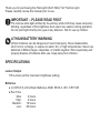
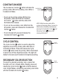
T-MAX NV
™
USER MANUAL
TABLE OF CONTENTS
Specifications................................................................................................................ 2
Components.................................................................................................................. 4
Battery Installation......................................................................................................... 4
Basic Functions............................................................................................................. 5
Lockout/Ready Mode............................................................................................... 5
Momentary Mode..................................................................................................... 5
Constant-On Mode.................................................................................................. 6
Cycle Control........................................................................................................... 6
Strobe Mode ........................................................................................................... 7
Multi-Color Safety Beacon Mode............................................................................. 8
Low Battery Indication................................................................................................... 8
Finger Loop................................................................................................................... 9
Steel Belt Clip.............................................................................................................. 10
Tactical Retention System (TRS) ................................................................................11
Lifetime Limited Warranty............................................................................................ 12
FIRST-LIGHT USA, LLC
205 S. Main Street
Seymour, IL 61875
Phone: 877.454.4450
Fax: 877.454.4420
Email: [email protected]
www.firstlight-usa.com
Thank you for purchasing the First-Light USA T-MAX™ NV Tactical Light.
Please carefully review this manual prior to use.
IMPORTANT – PLEASE READ FIRST
The intense white light emitted by the primary white LED may cause temporary
blinding, regardless of the brightness level used. Use caution during operation.
Do not point light directly into eyes at any distance. Not for use by children.
LITHIUM BATTERY WARNING
Lithium batteries can be dangerous if used improperly. Never disassemble,
short circuit, recharge, or expose to water, fire, or high temperatures. Never use
batteries of different ages, capacities, or brands together. Store separately and
properly dispose of batteries after use. Keep away from children.
SPECIFICATIONS
Lumen Output
700 Lumens (at the maximum brightness setting)
Batteries
● (2) CR123 3-Volt Lithium Batteries, ANSI: 5018LC, IEC: CR17345
● Run Time
Max:
High:
Medium:
Low:
2 hours
4 hours
16 hours
60 hours
NOTE: High quality, rechargeable CR123 batteries may be used to power the T-MAX™
NV Tactical Light. The user should identify the voltage capacity of any rechargeable
batteries prior to installing them into the T-MAX NV Tactical Light.
IMPORTANT: Never install any rechargeable CR123 batteries that exceed a
combined voltage of 8 volts as this will damage the internal circuitry and
void the warranty.
Environmental Specifications
● Normal Operating Temperatures: (-20°F) to 120°F
● Waterproof
REPLACEMENT PARTS
To order replacement parts, please call 877.454.4450 or visit www.firstlight-usa.com.
2
COMPONENTS
LAMP HOUSING
CRENULATED BEZEL
FINGER LOOP
CONTROL PANEL
STEEL BELT CLIP
BATTERY HOUSING/SLEEVE
BATTERIES
BATTERY INSTALLATION
CRENULATED
BATTERY CAP
STEP 1. R
emove battery cap. Insert two batteries “+” terminals first
(as shown above).
STEP 2. Reinstall battery cap. Hand-tighten until snug.
STEP 3. E
nsure batteries are properly installed by pressing any button on the control
panel. The red LED “lock” should illuminate indicating the light is in Lockout
Mode. If it does not, repeat Steps 1 and 2, ensuring both “+” terminals are
facing up.
3
BASIC FUNCTIONS
Control Panel Diagram
LOCK / UNLOCK
INDICATOR
CYCLE CONTROL
CONSTANT-ON
CONTROL
MOMENTARY
CONTROL
LOCKOUT/READY MODE
Lockout Mode prevents accidental illumination.
To unlock the light and enter Ready Mode,press
the Constant-On
and Cycle Control
buttons simultaneously and release. The green
“unlock” indicator will illuminate signaling that
visible light modes are active.
LOCK / UNLOCK
INDICATOR
CONSTANT-ON
CONTROL
To reenter Lockout Mode at any time during use,
press and hold the Constant-On
and Cycle
Control
buttons simultaneously for 1 second.
The red “lockout” indicator will illuminate.
MOMENTARY MODE
The Momentary Control
button activates the
primary white LED at maximum brightness when
pressed. When released, the white LED turns off.
NOTE: To momentarily activate the secondary colored LEDs from
the off position, press and hold the Cycle Control
button.
When released, the secondary LEDs turn off. The secondary
LEDs will illuminate at the last used Constant-On brightness level.
4
MOMENTARY
CONTROL
CYCLE
CONTROL
CONSTANT-ON MODE
The Constant-on Control
button activates the
primary white LED and secondary color LEDs in
Constant-On Mode.
•T
o turn on the primary white LED from the
off position, press and hold the ConstantOn Control
button until the white LED
illuminates then release.
• To turn on the secondary color LEDs from the
off position, press and release the Constant-On
Control
button.
•T
o turn the light off, press and release the
Constant-On Control
button.
CONSTANT-ON
CONTROL
NOTE: While the primary white LED is
activated in Momentary Mode, Constant-On
Mode can be activated by simultaneously
pressing the Constant-On Control
and
Momentary Control
buttons then
releasing both buttons.
CYCLE CONTROL
The Cycle Control
button is used to adjust the
brightness level of the primary white LED while in
Constant-On Mode. Press and release the Cycle
Control
button when the primary LED is illuminated
to select one of three brightness levels. The light will
default to the last used Constant-On brightness setting.
SECONDARY COLOR SELECTION
To select the desired secondary color, ensure that
the light is off, but in Ready Mode. Rapidly press and
release the Cycle Control
button until the desired
color of light flashes. Activate the secondary color LEDs
with the Constant-On Control
button.
CYCLE
CONTROL
CYCLE
CONTROL
5
DOUBLE-CLICK FOR COLOR
While in Lock Out Mode the last used secondary
LEDs can be activated by double-clicking the
Constant-On Control
button. This allows
access to the secondary color LEDs (defaulting
to the lowest brightness setting) and disables
the primary white LED.
CONSTANT-ON
CONTROL
CYCLE
CONTROL
Adjust the secondary color LEDs brightness
using the Cycle Control
button.
When the secondary color LEDs are turned off,
the light will return to Lockout Mode.
STROBE MODE
Activate strobe by pressing and holding the
Momentary Control
button with the base
of the thumb. Then press the Cycle Control
button with the front portion of the same thumb.
The strobe will activate as long as the Cycle
Control
button is pressed.
CYCLE
CONTROL
MOMENTARY
CONTROL
NOTE: Upon exiting Strobe Mode, the light
will default to the last used function.
6
MULTI-COLOR SAFETY BEACON MODE
The T-MAX™ NV features a red, white and green,
or a red, white and blue Safety Beacon. With the
light in Ready Mode, activate the Safety Beacon
by pressing and holding the Constant-On Control
button. As the Constant On Control
button
is held, the light will activate the white LED and
then enter the Multi-Color Safety Beacon Mode.
Once the Safety Beacon is activated, release the
Constant-On Control button. Press and release
the Constant-On Control
button again to turn
the Multi-Color Safety Beacon off.
LOW BATTERY
When the battery nears the end of its useful life
the red Lock/Unlock indicator will begin to flash.
Once the useful life of the batteries has been
reached the T-MAX NV will begin to limit its
output in order to extend run time.
CONSTANT-ON
CONTROL
NOTE: White Light Momentary Mode
can be activated while the Multi-Color
Safety Beacon is in use.
LOCK / UNLOCK
INDICATOR
7
NV MODE (IR MODE)
To enter NV Mode, which activates the T-MAX NV’s
secondary Infrared (IR) LEDs, the light must first
be in Lock Out Mode.
Simultaneously press and hold the Constant-On
Control
button and the Momentary Control
button until the red lock indicator flashes twice.
This is an indication that you have entered NV
Mode and the IR LEDs are ready to be activated.
CONSTANT-ON
CONTROL
MOMENTARY
CONTROL
NOTE: Infrared (IR) illumination is not
visible to the naked eye and is designed
for use with night vision equipment.
MOMENTARY IR MODE FUNCTION
The Momentary Control
button activates the
primary IR LEDs at maximum brightness when
pressed. When released, the IR LEDs turn off.
MOMENTARY
CONTROL
CONSTANT-ON IR MODE FUNCTION
Press and release the Constant-On Control
button to turn on the IR LEDs. Press and release
the Constant-On Control
button again to turn
off the IR LEDs.
8
CONSTANT-ON
CONTROL
NV MODE (IR MODE) CONTINUED
CYCLE CONTROL IR BRIGHTNESS FUNCTION
While in Constant-On, press and release the Cycle Control
button to select between three IR brightness settings.
CYCLE
CONTROL
IR BEACON FUNCTION
The Tomahawk NV features an integrated IR
beacon. To activate from the off position, press
and hold the Constant-On Control
button
for approximately 2 seconds. The IR beacon
will begin to flash. To turn off the beacon, simply
press and release the Constant-On Control
button again.
CONSTANT-ON
CONTROL
To exit NV Mode, re-enter Lock Out Mode by
pressing the Constant-On Control
button
and the Cycle Control
button simultaneously
until the red lock indictor illuminates.
9
FINGER LOOP
Your T-MAX™ NV comes equipped with a Finger
Loop installed in a neutral/straight-forward
position. In order to enhance the ergonomic
control of the T-MAX NV, it is recommended that
the Finger Loop be slightly offset to better align
the thumb with the control panel.
The Finger Loop can be moved by pushing it to
the desired position.
FINGER LOOP
INSTALLING FINGER LOOP
A smaller Finger Loop is also provided. In order
to install the smaller Finger Loop, loosen the
threaded connection between the lamp housing
and battery housing until the large Finger Loop is
loosened to a point at which it can be removed.
Insert the collar of the smaller Finger Loop so that
it is seated within the machined groove located at
the top of the battery housing.
IMPORTANT: Ensure that the Finger Loop
remains securely seated during use.
Hand-tighten the connection between
the battery housing and lamp housing as
firmly as possible.
10
LOOSEN HERE
T-MAX™ NV STEEL CLIP (IF EQUIPPED)
The T-MAX NV Steel Clip can be adjusted to any
desired position by loosening the connection between
the battery housing and the lamp housing to the point
where the Steel Clip can be moved.
Move the Steel Clip to the desired position and retighten the connection.
LOOSEN HERE
MOLLE/PALS Webbing Attachment
The T-MAX NV MOLLE Steel Clip is specially
designed to attaching securely to MOLLE/
PALS webbing. See Figure A to view suggested
mounting option.
Figure A: MOLLE Steel Clip
attached to MOLLE/PALS
webbing
11
TACTICAL RETENTION SYSTEM (TRS) (IF EQUIPPED)
The Tactical Retention System (TRS) will allow your T-MAX™ NV to be mounted to
MOLLE/PALS webbing for hands-free use. When horizontally mounted to TRS the
T-MAX NV can be rotated nearly 180° up or down.
To mount the Tomahawk to the TRS Receiver,
insert the dovetail sleeve on the Tomahawk’s
battery housing into the TRS Receiver until a
“click” is heard to ensure proper seating. To
release, push the spring-loaded button located
at the top of the Receiver then slide the dovetail
connection free.
12
FIRST-LIGHT USA, LLC LIFETIME LIMITED WARRANTY
The PERIOD OF WARRANTY shall be for the lifetime of the lighting device from date of purchase. First-Light USA will repair or replace,
free of charge, at First-Light USA’s option, any part due to defects in materials or workmanship. Certain countries and jurisdictions
restrict limited lifetime warranties. If you reside in one of these countries or jurisdictions, First-Light USA extends to you a 10 year limited
warranty, which maintains the following terms and conditions.
First-Light USA, at First-Light USA’s option, may refund the purchase price to the original owner if unable to make the product perform the
work for which it was designed by repair or replacement of a product of at least equal value. The limited warranty contained herein is the
purchaser’s exclusive remedy.
THIS WARRANTY EXCLUDES damage or defects caused by neglect, abuse, misuse, alteration, disassembly, improper maintenance or
accidents. Batteries, or damaged caused by defective or neglected batteries are excluded from this warranty. Accessory items are also
excluded from this warranty. Electronics (other than light emitting diodes (LEDs), are limited to a 3 year warranty with proof of purchase.
To obtain warranty service, call 877.454.4450 or send e-mail to [email protected].
First-Light USA will then issue a Return Merchandise Authorization (RMA) and instructions on warranty return. The original owner must
include the RMA upon returning the product in order to obtain warranty service from First-Light USA.
We will pay to ship the repaired or replaced product to the original owner’s address if located within United States. If the original owner’s
address is located outside of the United States, we will ship the product freight collect.
If we determine the remedy is not covered under this warranty, we will notify you and inform you of service options available on a fee
basis.
FIRST-LIGHT USA, LLC MAKES NO OTHER WARRANTY OF ANY KIND, EXPRESSED OR IMPLIED. ALL IMPLIED WARRANTIES,
TO INCLUDE BUT NOT LIMITED TO WARRANTIES OF MERCHANTABILITY AND FITNESS FOR A PARTICULAR PURPOSE WHICH
EXCEED THE OBLIGATIONS AND TIME LIMITS STATED IN THIS WARRANTY ARE HEREBY DISCLAIMED BY FIRST-LIGHT USA,
LLC AND EXCLUDED FROM THIS LIMITED WARRANTY. SOME STATES DO NOT ALLOW LIMITATIONS ON HOW LONG AN IMPLIED
WARRANTY LASTS, SO THE ABOVE LIMITATION MAY NOT APPLY TO YOU.
ALSO EXCLUDED FROM THIS WARRANTY ARE ANY INCIDENTAL OR CONSEQUENTIAL DAMAGES INCLUDING LOSS OF USE.
SOME STATES DO NOT ALLOW THE EXCLUSION OR LIMITATION OF INCIDENTAL OR CONSEQUENTIAL DAMAGES; EXCLUSIONS
MAY NOT APPLY TO YOU.
THIS WARRANTY GIVES YOU SPECIFIC LEGAL RIGHTS AND YOU MAY ALSO HAVE OTHER RIGHTS THAT VARY FROM STATE
TO STATE.
FIRST-LIGHT USA, LLC
WARRANTY AND SERVICE DEPARTMENT
205 S. Main Street, Seymour, IL 61875
Phone: 877.454.4450
Fax: 877.454.4420
Email: [email protected]
WHEN YOUR LIGHT DEPENDS ON IT.®
www.firstlight-usa.com
REV_15-03