1
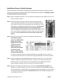
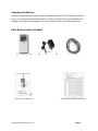
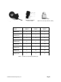
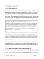
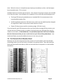
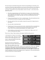
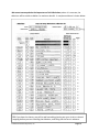
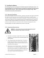
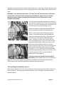
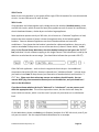
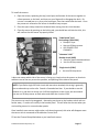
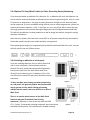
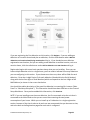
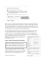
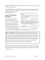
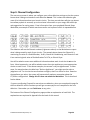
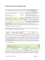
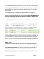
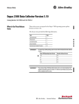
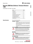
eMonitor™ Version 2.0 Installation Guide Rev 1.2 Installation Process: Quick Overview Please review the full Installation Guide before proceeding; this Overview provides the steps only, but not the level of detail you will need to safely install the eMonitor. Installation should be performed by a licensed electrician. Step 1: Mount the eMonitor Base Unit. This unit should be mounted on the wall adjacent to the circuit panel it is going to monitor. Step 2: Turn off the power to the home, open the circuit panel (unscrew the cover), and clamp the eMonitor sensors onto the incoming Main power lines as well as all other circuits being monitored, recording each circuit’s information on the Channel Setup Worksheet as you go. Do not attempt to complete this installation unless you are very familiar with the electrical components and operation of the circuit breaker panel. Please refer to the body of the Installation Guide for safety issues and complete instructions; do not install the sensors until you have read the entire manual. Step 3: Connect the other end of the sensors to the eMonitor Channel ports. Note: When using two sensors on a 240V (double) breaker, they must be plugged into consecutive channel ports on the eMonitor; please see Section 2.6 of this manual on when to use two sensors. Sensors may be oriented in either direction. You can then organize the wires with the provided wire ties and organizer tube. Close the circuit panel, turn power back on to the home, and plug the eMonitor into an electrical outlet. Step 4: Connect the eMonitor to the broadband Internet network in your home. This version of the eMonitor requires a wired Ethernet connection. If there is no easy access to an Ethernet connection near your circuit panel, and it is not possible to run a long Ethernet cable, an Ethernet Bridge is available. Please consult with your Authorized Dealer. Step 5: Register and configure the eMonitor online. Please go to http://emonitor.us/register and follow the on-screen instructions. This process can, but need not, be completed by the person who installed the unit, and will require a completed Channel Setup Worksheet. You will be able to access your eMonitor Dashboard at www.emonitor.us after you complete the Registration and Configuration process. © 2010 Powerhouse Dynamics, Inc. Page 2 eMonitorTM Version 2.0 Installation Guide Table of Contents Installation Guide .................................................................................................................... 1 Installation Process: Quick Overview ...................................................................................... 2 Installation Guide ................................................................................................................ 3 1. Getting Started ............................................................................................................... 4 Unpacking the eMonitor ............................................................................................... 5 Parts & Accessories Included: ....................................................................................... 5 Tools .............................................................................................................................. 7 2. Setting up the eMonitor ....................................................................................... 8 2.1 The eMonitor Control Unit ..................................................................................... 8 2.2 The Sensors (also known as Current Transformers or CT’s) ......................... 8 2.3 The Electrical (Circuit Breaker) Panel ..................................................................... 9 2.4 Channel Setup Worksheet .................................................................................... 10 2.5 Installing the eMonitor ......................................................................................... 13 2.6 Sensor Installation....................................................................................... 14 2.7 Powering Up and Connecting the eMonitor Control Unit .................................... 20 Connecting to the Home Broadband Network ..................................................... 21 Verify the Ethernet Connection ............................................................................ 22 3. Registering and Configuring Your eMonitor ....................................................... 22 Step 1: Contact and Location Information. ......................................................... 24 Step 2: Utility and Rate Information .................................................................... 25 Step 3: Channel Configuration ............................................................................. 26 Step 4: Alerts........................................................................................................ 28 Appendices ..................................................................................................................... 32 A. How to Prioritize the Circuits to Monitor with the eMonitor ...................................... 32 B. Explanations of Fields on Channel Configuration Page ................................................ 34 C. Frequently Asked Questions ......................................................................................... 36 D. Support & Troubleshooting .......................................................................................... 37 E. Specifications for the eMonitor .................................................................................... 39 Warnings ........................................................................................................................... 40 Warranty ........................................................................................................................... 41 © 2010 Powerhouse Dynamics, Inc. Page 3 1. Getting Started NOTE: Installation should not be started until the qualified installer has read this entire Installation Guide. Important Safety Information The eMonitor is one of the first home energy management solutions that monitors all of the circuits in your home independently, and therefore is able to provide you with a detailed view of your electricity usage. In order to do this, sensors need to be installed on each circuit breaker inside your electrical panel. The installation is very straightforward, and every effort has been made to provide for the safe, secure installation of the eMonitor. However, the installation of the eMonitor requires the cover of the main electrical circuit breaker panel to be removed. When this is done, there is the potential hazard of shock, burn, or even electrocution. Even when the Main Circuit Breaker has been turned to the “OFF” position, there may still be areas within the circuit breaker panel that are electrified, or “hot”. Installation should be performed by a licensed electrician. This model of the eMonitor is suitable for installation with 120/240V single-phase 60Hz service, normally found in North America (USA, Canada, Mexico and portions of the Caribbean). It is not suitable for 3-phase service, or for 230V 50Hz service commonly found in other regions of the world. All wiring in the United States must be installed in accordance with the latest adopted edition of the National Electrical Code (ANSI/NFPA 70, NEC) and state or local requirements. All wiring in Canada must be installed in accordance with the latest adopted edition of the Canadian Electrical Code (CSA C22.2 CEC, Part I) and any provincial or local requirements. A typical installation of a 24-channel eMonitor unit should take approximately one hour. © 2010 Powerhouse Dynamics, Inc. Page 4 Unpacking the eMonitor Unpack the eMonitor box. Be very careful of the eMonitor Base Unit itself (the silver-colored box) as it is a sensitive measuring instrument. Check to see that all parts are included in the package. If you are missing any parts from the list, please contact your Authorized Dealer. Parts & Accessories Included: The eMonitor Base Unit Installation Guide (what you are reading now) © 2010 Powerhouse Dynamics, Inc. AC Power Supply 12V, 2 Amp 5ft. Ethernet Cable eMonitor Channel Setup Worksheet (3) Page 5 Spring-Loaded 150-Amp Sensors MODEL Split-Core CT 50-Amp Sensors—black Split-Core CT 20-Amp Sensors—white ) 150A CTs 50A CTs 20A CTs eMonitor-12 2 6 4 eMonitor-12r 2 6 4 eMonitor-12s 0 6 6 eMonitor-24s 0 8 16 eMonitor-24 2 6 16 eMonitor-24r 2 7 15 eMonitor-44 2 10 32 eMonitor-44r 2 11 31 Table 1 – Number of CTs provided by Model Type © 2010 Powerhouse Dynamics, Inc. Page 6 Your eMonitor may also have come with an optional Ethernet Bridge, described later, if your Authorized Dealer determined that you needed one. Tools You will need the following tools: • Flathead screwdriver • Phillips-head screwdriver – small • Small hammer • Pliers • Utility knife • Flashlight (a head lamp if you have it!) © 2010 Powerhouse Dynamics, Inc. Page 7 2. Setting up the eMonitor 2.1 The eMonitor Base Unit The “brain” of the eMonitor is the eMonitor Base Unit. Normally it is mounted on the wall near your home’s circuit breaker panel. Your eMonitor comes with a set of sensors, the total depending upon the model you purchased, as described earlier. Generally, on all Main Electric Panels, two sensors are used to monitor power coming in through the Mains, which are the large wires coming into the circuit panel (although the eMonitor can also monitor additional power inputs). The remaining sensors are used to monitor individual circuits. If there are more than 22 circuits on your circuit panel and you have not purchased an eMonitor-44, you could either add a second eMonitor, OR decide to monitor only some of your circuits. If You Have More Than One Circuit Breaker Panel: This manual covers installation at a single circuit breaker panel. If you also have one or more sub-panels you may install eMonitor s-model Base Units at each sub-panel, and monitor an aggregate of up to 200 circuits. Sub-panel installation is virtually identical to installation at the Main Panel, with an exception described on page 18. Appendix A will help you decide which circuits to monitor if you have more than 22 and decide not to install an additional eMonitor Base Unit or use an eMonitor-44. On the left side of the Base Unit are 24 ports, or Channels, for connecting the sensors. At the bottom of the Base Unit are the power port for the power adapter and an Ethernet jack to connect to a home network. Next to the Ethernet port is a small serial port for future optional connections. If you ordered an eMonitor-44, there will be an additional 20 Channels on the right hand side of the unit. The 24 sensor ports are labelled 1 through 24, starting at the top. It’s important to record accurately which ports are connected to which circuits, using the Channel Setup Worksheet included with your unit, as described later. (NOTE: if you purchased an eMonitor-12, 12s, or 12r unit, you will only have a total of 12 sensors to connect. You can upgrade to an eMonitor 24 at any time). 2.2 The Sensors (also known as Current Transformers or CTs) For each circuit you wish to monitor, a sensor needs to be clamped around the wire coming out of the breaker in the panel. You will also install a large sensor on each of the Main lines feeding the panel. NOTE: Sensors are clamped around the insulated portion of the wire, NOT on bare © 2010 Powerhouse Dynamics, Inc. Page 8 wires. When the sensor is clamped securely closed (you should hear a click), it will be slightly loose around the wire. This is normal. Included in the box are three types of sensors. The number of each type of sensor was included in the Parts list above. As an example, for an eMonitor-24 you will have the following sensors: Two large 150-Amp spring loaded sensors, intended ONLY for measurement of the incoming (Main) power lines. Six 50-Amp (black) sensors for 240-Volt circuits, which are the double breakers designed for large electric loads, such as electric water heaters or dryers. Sixteen 20-Amp sensors used for monitoring single, 120-Volt circuits. If you end up with more 50-Amp sensors than you need, and not enough 20-Amp sensors, you may use the extra 50-Amp sensors on smaller circuits and vice versa, although they may not measure as accurately. As described later, it is particularly important in this case to identify the size of the sensors that you use on each circuit on your Channel Setup Worksheet. Your Authorized Dealer can provide additional sensors in the sizes you need. 2.3 The Electrical (Circuit Breaker) Panel Most (but not all) electrical panels have two columns of circuit breakers, with each breaker controlling power to part of your home, as shown in the picture below. There will usually be labels associated with the breakers, either on the inside door of the panel or on the breakers themselves. © 2010 Powerhouse Dynamics, Inc. Page 9 Generally, each circuit breaker will be labelled, but in some cases, especially in older or remodelled homes, the labels are incorrect or missing. (NOTE: Not all circuit breakers are used in all cases, so a missing label could simply mean that the circuit is not powering anything). Before physically installing the eMonitor, it is suggested that you verify the labels on each circuit breaker inside the panel. Taking the time to identify exactly which breaker controls which items will make your eMonitor experience more productive. Verifying the labels will also come in handy if you ever experience a problem and want to check the appropriate circuit breaker. Finding Which Circuits Power Which Devices and Appliances: If you are concerned about the accuracy of your labels, the easiest way to verify them is to turn “on” all electrical appliances, lights and outlets in your home, and then turn “off” one breaker at a time and observe where power turns off. NOTE: Be sure to turn off computers or sensitive equipment before doing this test! Also check wall outlets, clothes washer/ dryers, outdoor lighting and other items that may not be as visible. Of course, you can also check only the circuit breakers that you might not be sure about. Electricians will often have equipment that can help quickly test breaker connections. Use the Channel Setup Worksheet to mark circuits as you identify them. It may actually be easier to do this after the eMonitor is installed, since you will be able to quickly see which circuits are showing changes. You can always change circuit information after installation. 2.4 Channel Setup Worksheet During the Installation process, the installer needs to fill out the Channel Setup Worksheet. An example is given below for an eMonitor-24r unit. (The r designation stands for renewable energy and is used for homes with Solar Photovoltaics, Wind Turbines, or other renewable energy sources). This Worksheet is critical for configuring the eMonitor correctly to measure the energy use accurately on different circuits. To make your job easier, this form should be filled out as the sensors are being attached. The form is divided into two sections. The upper section asks for general information about the home and the eMonitor, specifically the following: Serial number of the eMonitor unit being installed Your description of the Circuit Panel to which the eMonitor is attached (e.g. “Main Panel”) Location (street address) of the installation © 2010 Powerhouse Dynamics, Inc. Page 10 The next section has information about each “Channel” that the eMonitor is monitoring. We use the term Channel here because different circuit panels will have different circuit numbering schemes; because a single Channel may be used to monitor two circuits, as described in the next section; and because it may not be possible to monitor all circuits. In this section of the Worksheet, please: Record the mapping between the Circuit Number as it appears on the electrical panel and the eMonitor Channel Number. (Once the system is configured you will not need to worry about the circuit numbers any longer, since the key matching item will be the Channel Number). Check the Double Breaker? box if this is a double breaker. This tells the eMonitor that it is a 240-Volt circuit, which is necessary for correct calculations. Enter the rated size of the circuit breaker, measured in amps (this is always shown on the breaker). Enter the Label, as described earlier. Check the type of sensor you used on the circuit. As described earlier, you should place the 20-Amp sensors on 120-Volt circuits and the 50-Amp sensors on the 240-Volt circuits, but this may not always be possible given your supply of sensors. Indicate whether you have used 2 sensors on a Double Circuit. When to use 1 or 2 sensors is described further below. There is also a “Notes” field at the back of the page to identify anything unusual. A close-up photo of a typical circuit breaker panel is shown at right. Notice the six breaker switches and the amperage label on each circuit – in this case three 20-Amp breakers and three 15-Amp breakers. General instructions for filling out the Worksheet can be found on the back of the form. There are multiple copies of the Worksheet included, in case you make a mistake or want to generate a neater copy. If you are not the person who will be entering this information online during the registration and configuration process, please make sure the information is neat and legible to someone else. Once the Worksheet is used for the Configuration part of registration, a copy should be kept by the Authorized Dealer for support purposes. © 2010 Powerhouse Dynamics, Inc. Page 11 We cannot overemphasize the importance of this Worksheet; unless it is accurate, the eMonitor will be unable to deliver its maximum benefit. A sample worksheet is shown below. TIP: If you have the chance, you will be well served by planning out your circuit to channel mapping before you start installing the eMonitor, and filling out the form in advance. © 2010 Powerhouse Dynamics, Inc. Page 12 2.5 Installing the eMonitor The following steps involve opening the circuit breaker panel and installing the sensors. It is extremely dangerous for an untrained person to attempt this installation since high voltage is always present in the panel. Injury or death could result from improper usage. Have a licensed electrician perform the installation! 2.5.1 Mounting the eMonitor Identify where the Base Unit will be mounted – generally on the wall to the right of the breaker box is best, since the sensor ports are on the left side of the eMonitor and will be easily accessible. However, anywhere near the panel is acceptable - as long as the sensor wires will reach it easily, and there is room to plug the sensors into the eMonitor Base Unit and for the installer to read the numbered labels on the Channel ports. Once you have located the best position to mount the Base Unit, use one of the four included mounting screws in each mounting flange on the sides of the Base Unit to secure it to the wall. 2.5.2 Preparing the Electrical Panel WARNING – only a licensed electrician should undertake this and all subsequent installation steps, based on local codes. 1. Shut down any computers, digital video recorders, medical equipment, or other devices that could be damaged if shut down suddenly. 2. Turn off power at the main breaker switch. This will cut power to the entire home, so be sure to have alternate lighting (flashlight or battery-powered headlamp) for the remainder of the installation. 3. Remove the cover from breaker panel. Generally this is done with four or six screws on the edges of the panel. Place the cover on the floor or an elevated surface so you still can read the circuit breaker labels (if, as is often the case, they are located inside the panel door). © 2010 Powerhouse Dynamics, Inc. Page 13 4. Now, locate the most convenient 1-1/2-inch knock-out hole along the bottom or sides of the panel box. Use a screwdriver, small hammer or a set of pliers (probably best choice) to pry out one of these access holes so as to be able to route the sensor wires through to the eMonitor Base Unit. Determine the best route for the sensor wires to reduce clutter in the breaker panel. 5. Install the included yellow plastic grommet into the knockout. This will prevent the sharp edges of the newly made hole from damaging the sensor wires. NOTE: DO NOT touch wires or bare metal except for the circuit panel itself. 2.6 Sensor Installation Unpack and unwind all of the sensor wires. Tip: Hang sensors over a back of a chair or something similar. This will allow the wires to “relax”, especially if they’re cold, and will keep them from tangling as you install them one by one. 2.6.1 Installing the Main Power Sensors Locate the two big 150-Amp spring-loaded eMonitor sensors. Identify the two incoming main power lines near the top of the panel. © 2010 Powerhouse Dynamics, Inc. Page 14 Open the spring-loaded sensor by firmly pressing the lever on the side, and place the open jaws around the insulated area each of the incoming power lines, above where they connect to the panel. WARNING – even with the main breaker “off” these lines will still have power to them and electrocution could result from touching the electrified areas. Make sure you avoid the mounting screws as shown at the bottom of the picture at left! They may be in other locations in your panel. Once the jaws are around the power wire, simply let go of the lever and the sensor “ring” will close around the wire. It’s normal for the sensor to slide down the wire and rest close to the mounting screws. Repeat this step for installing the second 150-Amp sensor around the second incoming power line. NOTE: In some panels with 400-Amp service or greater it is possible that there will be additional input lines coming into the panel. Channels 3-6 of the eMonitor can be used for additional power inputs, coming from either your electric utility or from a power generator in your home such as solar photovoltaic (PV) panels. If there are one or more additional circuits labelled as Mains or a Power Source, clamp 50-Amp sensors on to them using the process described below, attach those sensors to Channels 3, 4, 5 or 6, and fill out the Channel Setup Worksheet appropriately, as described earlier. (If the 50-Amp sensors do not fit, ask your dealer for additional 150-Amp sensors.) If the large sensors do not fully close around the Main wires, which could be the case if you have very large electrical service coming into your home, the eMonitor will work but lose accuracy. Please consult with your Authorized Dealer about getting larger sensors. 2.6.2 Installing Circuit Breaker Sensors With the main breaker still “off”, start installing the smaller sensors on each of the circuit lines to be monitored. Please pay close attention to when to use a 50-Amp or 20-Amp sensor, as described below. © 2010 Powerhouse Dynamics, Inc. Page 15 120V Circuits Most of the circuit breakers in your panel will be single 120-Volt breakers for normal household circuits. Use one 20A sensor for each of these. 240V circuits If two breakers are locked together with a bridge across the switches (double breakers), these are 240-Volt circuits, which are used for heavy-duty appliances such as central air conditioners, electric baseboard heaters, clothes dryers and other large appliances. Some appliances operate strictly on 240 Volts; this is known as a “balanced” appliance or load, because the same amount of power is drawn through each wire of the locked-together breakers. Common balanced appliances are electric baseboard heat and central air conditioners. If you know that the breaker is attached to a balanced appliance, then you only need to attach one 50-Amp sensor to one of the two wires (it doesn’t matter which). In this case, on the Channel Setup Worksheet, check the double breaker box but ignore the “2 CTs?” box (and show 2 circuit numbers mapping to this single Channel. This information is used by the eMonitor to calculate the correct usage. (You should also indicate that you used a 50A CT). Other 240-Volt appliances – such as electric ranges and electric dryers – have additional components that draw 120-Volts; these are referred to as “unbalanced loads”. In these cases, you need to install two 50-Amp sensors (see illustration of breakers below) and check the “2 CTs?” box. Please note that where two sensors are used on a double breaker, the two sensors MUST plug into consecutive Channel ports on the eMonitor, and you should use 2 rows on the Worksheet. If you do not know whether the load is “balanced” or “unbalanced”, use two sensors, and check the appropriate box. This will use up another sensor, but the results will always be correct with two sensors, which is not the case if you put only one sensor on an unbalanced load. On the Worksheet, please note both circuit (breaker) numbers for a 240-Volt circuit, even if you only use one sensor. See the sample filled out Worksheet for an example. © 2010 Powerhouse Dynamics, Inc. Page 16 To install the sensors: 1. Open the sensor, squeezing the top (round part) and bottom of the sensor together to relieve pressure on the latch, and then use your fingernail to disengage the latch. Do not use a screwdriver or try to pry the latch open, since that could break the latch. Once the pressure is relieved on the sensor it should be easy to open. 2. Place the open clamp around the insulated wire coming into the circuit breaker. 3. Close the sensor by pressing on the locking tab; you should hear a distinctive click; this will confirm that the sensor is properly closed. “Unbalanced” load Dual voltage (240+120V) Example: Dryer Use two 50-Amp sensors USE CONSECUTIVE CHANNELS “Balanced” load Double circuit (240V) Example: electric baseboard heat Use one 50-Amp sensor Single circuit (120V) Use one 20-Amp sensor It does not matter which side of the sensor is facing up; simply orient the sensors so that their cables are out of the way as much as possible, and pointing to the sides of the panel. NOTE: If you find a single 120-Volt circuit with two wires attached, this wiring is generally not to code and may not be safe. Consult a licensed electrician. If you decide to use this breaker as-is, and there is clearly not a 240-Volt appliance on the circuit, we recommend you use one 20-Amp sensor on both wires and check the circuit as 120V. The sensors may need to be staggered – alternating one closer to the breaker switch and one farther away – in order to fit neatly in the breaker panel. This will often be the case when you are installing sensors in narrow breaker panels. Once installed, some sensors might make a soft humming sound; this noise will disappear once the sensor wire is connected to the eMonitor Control Unit. Fill out the Channel Setup Worksheet as you install each sensor. © 2010 Powerhouse Dynamics, Inc. Page 17 2.6.3 Optional PV Solar/Wind Turbine (or Other Generating Device) Monitoring If you have purchased an eMonitor-24r, eMonitor-12r, or eMonitor-44r unit, the eMonitor can also be used to measure the power produced from an electricity-generating unit, such as a solar PV system or a wind turbine. Any type of power generation brought into the electrical panel can be monitored. (For non-renewable energy sources, such as a back-up generator, you do not need to purchase an eMonitor r unit). If you have an r unit, you will be able to select the type of energy production unit you have during the Registration and Configuration described later. This will tell the eMonitor to show production as well as usage information, along with savings and other calculations. Note that only systems that have their inverted (DC to AC) power output directly connected to the breaker panel (normally via a double breaker) are supported. These power-generating units can generally be treated like a balanced 240-Volt circuit, and you will only need to use one 50-Amp sensor. 2.6.4 Installing an eMonitor at a Sub-panel If you are installing eMonitor Units at a Main Panel and one or more sub-panels, the installation process is identical for each, except that sub-panels will generally have power inputs from the Main Panel rather than directly from the electric grid. An eMonitor-12s or 24s unit (where the s stands for sub-panel) should be used on sub-panels. If there are Main wires coming into what you perceive as a sub-panel, this generally implies that you have 400 amp or greater service, which is being split among multiple electric panels, each one of which is in effect a Main Panel. Figure A There is no need to attach sensors to the Main Panel feed to a sub-panel if the Main Panel is being monitored. (eMonitor s-units do not ship with the 150A CTs). Further, if sub-panels are being monitored, do not put sensors on the Main circuits FigurePanel B that feed the sub-panels. This would result in double counting. © 2010 Powerhouse Dynamics, Inc. Page 18 If you are not separately monitoring a sub-panel, then it does make sense to monitor the circuits feeding the sub-panel (see Figure b above). Sub-panel feeds should be treated identically to 240-Volt circuits. 2.6.5 Connecting the Sensors to the Base Unit As each sensor is installed, neatly and carefully thread the lead wire through the grommet and connect it to the appropriately numbered Channel port on the eMonitor Base Unit. The sensor wire plug will lock in to each numbered Channel port. Check that the Channel port connections match what is written on the Channel Setup Worksheet, and that any pairs of sensors used on 240-Volt double breakers are plugged into consecutive ports. A sensor wire plug is shown above. It is a good idea to add a label to each sensor wire which corresponds to the numbered Channel port on the eMonitor Base Unit (doing it on both ends of the sensor is even better). This way if you need to replace the eMonitor, it is easy to figure out where the sensors should plug in. 2.6.6 Organizing the Sensor Wires After all the sensors are installed in the circuit breaker panel and the wires are connected to the eMonitor Base Unit, the set of 24 loose wires can look quite messy. So, now it is time to clean up the wires and make the installation neat and organized. Organize the loose sensor wires on the left and right side of the inside of the breaker box, using six or eight of the included wire ties to prevent movement and allow the cover to be affixed. Once the sensor wires are neatly organized inside the panel, you can then organize the wires between the knock-out hole and the eMonitor Base Unit. Start by collecting the wires and using the remaining wire ties, working your way from the eMonitor Base Unit towards the electrical panel. Understand that the shortest sensor wires dictate the length of the collection of wires between the eMonitor Base Unit and the panel. The extra, slack wire can generally be gathered neatly inside the panel near the knock-out hole, or just outside the hole. © 2010 Powerhouse Dynamics, Inc. Page 19 When you are finished, carefully cut the excess part of the wire ties with a wire cutter or strong scissors, being extra careful not to cut the wires accidentally! 2.6.7 Mounting the Black Cable Organizer Use the black cable management tube/organizer to neaten the bundle of sensor lead wires going to the eMonitor. Start from the eMonitor Base Unit, open the split tube and carefully put the first part around the sensor wires close to where they mount to the eMonitor control unit. Work your way inch-by-inch, carefully pushing all the wires into the black tube. The cable organizer is large enough to cover possible sensor wire slack close to the panel. Congratulations! You have now finished the bulk of the installation and can close the circuit panel and turn the Main power to the house back on. 2.7 Powering Up and Connecting the eMonitor Base Unit You are now ready to plug the eMonitor power supply in to an available wall outlet and then to the eMonitor power port located on its lower left side. The eMonitor Base Unit will now boot up, and you will see the display light up. The “Status” light will glow green. On the start-up display you should see date and time information on the first line, total home power consumption in Watts on the second line, and the home’s voltage (which is actually being measured by the power supply unit itself and should be somewhere around 120V) on the last line. Date and time information will become accurate after the eMonitor Base Unit has been registered online. © 2010 Powerhouse Dynamics, Inc. Page 20 Connecting to the Home Broadband Network The eMonitor is designed to transmit data in near-real time over the Internet to the eMonitor Servers where data is analyzed and presented on the eMonitor Dashboard (described in the eMonitor User Manual which is accessible on-line via the Support link of the eMonitor Dashboard, or at http://docs.emonitor.us). The current version of the eMonitor requires an Ethernet connection. Connect the included green, 5-ft. Ethernet cable to the eMonitor Ethernet port on the bottom of the eMonitor Base Unit and to your home network via an Ethernet jack located near the eMonitor, or directly to a vacant port on your network router or switch. If there is no nearby access to the home network, there are several choices. First, it is possible to run a longer Ethernet cable (not included) to attach your router or switch. Second, your Authorized Dealer can provide a WiFi or Powerline Ethernet Bridge. A Powerline Bridge works as follows. 1. Use the Ethernet cable to connect the eMonitor Base Unit to the Ethernet port on one end of the Bridge (i.e. one of two provided Ethernet Bridge units), and plug that Bridge into the wall. 2. Connect an Ethernet cable between the Ethernet port on the second end of the Bridge (i.e. the second unit provided) and your router or switch, and plug that unit into a power outlet. The data will flow over the home power line between the two ends of the Bridge. This should work out of the box with no further set-up required. Refer to the manual that comes with the Ethernet Bridge if there are any issues. It is possible, but not likely, that another electronic system in the home could conflict with the Ethernet Bridge. NOTE: Avoid plugging a Powerline Ethernet Bridge into a power strip; particularly one © 2010 Powerhouse Dynamics, Inc. Page 21 with any filtering. Your Authorized Dealer may have other devices that can play the same role as the Ethernet Bridge. Verify the Ethernet Connection Once the eMonitor Base Unit is powered up and connected to the Internet, it will automatically attempt to communicate with the eMonitor Server. The eMonitor uploads data every 60 seconds; this data is an average based on local measurements every second by the sensors inside the circuit panel. The eMonitor’s yellow “Network” light will flash for one to three seconds every minute, indicating that communication to the eMonitor Server is occurring. If for some reason communication fails, the yellow “Network” light will stay on. Once the first successful communication has taken place between the eMonitor Base Unit and the eMonitor Server, the date and time information on the eMonitor Base Unit will be updated with the date and time information from the eMonitor Server. You can verify that the eMonitor Base Unit is communicating with the local Ethernet router or switch by pressing the down arrow on the eMonitor Control Unit keypad once to view the network settings screen. If an IP address like 192.168.1.x is displayed, that means the Base Unit is being seen on the local home network. On the same screen you will also find your eMonitor’s unique MAC (Media Access Control) address – this number should match the MAC number printed on the label on your eMonitor Base Unit. Congratulations! If everything is working, your eMonitor hardware set-up is complete! 3. Registering and Configuring your eMonitor The next step in the process is Registration and Configuration, which is performed online. This can be completed by the homeowner or by the installer, if different, and is also described in the eMonitor Dashboard User Manual. Please note that until Registration and Configuration is complete, you cannot access the data other than on the display and no data will be stored. To begin the Registration and Configuration process, go to: http://emonitor.us/register © 2010 Powerhouse Dynamics, Inc. Page 22 If you are registering the first eMonitor to this location, click Register. If you are adding an eMonitor to a location that already has an eMonitor, click the radio button under Add this eMonitor to a location already being monitored and log in. If you already have an eMonitor registered at one location, and you are adding a new eMonitor at another location, such as a vacation home, click the radio button under Add an eMonitor to a new location and log in. Registration begins with some basic questions about what you are installing. Since you can have multiple eMonitor units in a single home, you first need to indicate how many eMonitors you are configuring in this session. If you choose more than one, there will be fields for each eMonitor. Enter the six-digit Device ID for each eMonitor (found within the Serial Number), along with the last four digits of Serial Number (which corresponds to the last 4 digits of the MAC Address) as shown in the screen shot below. You should also add a description of the panel the eMonitor is measuring (for instance “Main Panel” or “Workshop Sub-panel”). This information should have been filled out on the Channel Setup Worksheet. Once you have added this information, click Continue. NOTE: If you are installing more than one eMonitor, the first one needs to be the unit that is connected to the Main Panel so that you are sure to be measuring the total power consumption of your home. While you can install up to 5 eMonitors in a single registration session, because of the time it takes to do each one we recommend that you do one at a time, and come back to the Registration page after each unit is configured. © 2010 Powerhouse Dynamics, Inc. Page 23 NOTE: If you see a “Not Valid” notice after you press Continue or on entering the Device ID or MAC, it means you have entered a non-valid Device ID. Please re-check the Device ID (found within the Serial Number) first on the installation form and, if that is same, check the one on the eMonitor Base Unit itself. In the unlikely event the number is still not valid, and you’re sure you have entered it correctly, please contact your Authorized Dealer. You are now ready to enter information about your home and your home’s circuits. All this information helps the eMonitor make accurate calculations and recommendations. The process has four steps. You will be guided through each one. If you can’t complete all four steps in a single session, you may save your entries for later by clicking the Finish Later button, which will appear beginning with Step 3. When you click Finish Later, you will be able to log-in to registration and pick up where you left off. Step 1: Contact and Location Information NOTE: If you are adding an eMonitor to an existing location, the online registration screen will skip this Step as well as Step 2, and will take you directly to Step 3. Enter your contact and related information. Required fields are marked by an asterisk. If you are an existing user registering an eMonitor at a new location, your name and other basic information will already be filled out. For © 2010 Powerhouse Dynamics, Inc. Page 24 Location Description, choose a name that describes the location of this installation, for instance “Home” or “Vacation Condo”. If you click Continue with incomplete information you will be notified in red text of the fields you left out or entered in an invalid format. Remember to check the “I have read & agree to the license agreement” checkbox on the bottom of the page. Step 2: Utility and Rate Information Next, confirm your electric utility company and your electric rate (measured in cents per kilowatt hour, or kWh). The eMonitor has a database that identifies your utility based on your zip code, but homes in some zip codes may be served by more than one utility, so you may need to choose one from the list. If the eMonitor cannot locate your utility, check the Show all utilities in my state checkbox for a full state list. A Note on Utility Rates: The eMonitor database reports average residential rates for each utility. This works extremely well in getting a sense of the costs of different appliances in your home. However, the cost estimates generated by the eMonitor cannot take into account all the complex formulas or special rate programs your utility uses unless there is an arrangement with the utility. Neither will the eMonitor’s measuring period necessarily be the same time period reflected on your utility bill, so trying to compare them is not recommended. You may be able to enter a better estimate of your average rate by dividing your total bill by the number of kilowatt hours reported on your bill in the provided calculator. In addition to the Utility Rate data, this page will also list what is available from Public Records data on the size and year built of your house. This information is important for analyzing your energy use, so please correct the information if you do not believe it to be accurate, or fill in anything missing. © 2010 Powerhouse Dynamics, Inc. Page 25 Step 3: Channel Configuration The next set-up screen is where you configure your online eMonitor settings so that the system knows what is being monitored on each eMonitor Channel. This is where the eMonitor gets most of its information about your home’s circuits. The time you take here will give you almost immediate payback in accurate, up-to-the-minute information on your usage, and useful tips and suggestions for saving power. Enter information from your completed Channel Setup Worksheet, an example of which was shown earlier and a piece of which is repeated below. The eMonitor will use the Channel numbers (rightmost column) on the Worksheet to report what is being served by each of your circuits. The example above shows that Channel 4 is monitoring one wire of a Double Breaker, 3a & b, Central Air Conditioning, and Channels 5 and 6 are monitoring both wires of Double Breaker 7a & 7b, an Electric Dryer. You will be asked to enter some additional information about each circuit that is not on the form. Most importantly, you will be asked to enter the major appliance or most appropriate choice on each circuit. In the above examples, the answer is very straightforward. In other cases, for example where the label says “Kitchen Appliances”, you might need to make a judgement call. For circuits that serve outlets and lights, there is a choice for that. Based on the appliance you select, the system will automatically make an assumption about the CT/Sensor configuration. Change this if it does not match the Worksheet. This is described further below. If you are configuring Channels for more than one eMonitor, when you complete this page for the first eMonitor and hit Continue you will get a new empty form to complete for the next eMonitor. Remember you can Finish Later at any point. The bottom of the Channel Configuration page provides an explanation of each field. The explanations are reprinted in Appendix B at the back of this manual. © 2010 Powerhouse Dynamics, Inc. Page 26 Filling Out the Channel Configuration Page First, review the general information at the top of the page. eMonitor Serial Number is taken from what you entered earlier and cannot be edited. You can edit the Panel Description. Channels 1 and 2, Main Power, are pre-filled out and have no settings to be entered on a Main Panel. (Brackets will automatically appear for double breakers with 2 CTs). You will be able to use these Channels on subpanels. NOTE: on a small subset of electric panels the Main Power wires are not accessible, and you will not be able to attach CTs. If you have this situation, click the Computed Mains checkbox and the system will use the sum of the individual circuits to calculate total power. For this to be reasonably accurate, you will need to ensure that you are monitoring all or virtually all of your circuits. Now you’re ready to fill out information for each Channel. We’ll show the worksheet and the Channel Configuration Screen together for reference. Channel 3 has information, which means it’s in use, so check the In Use box. This will enable you to enter data in this row. You can enter the Circuit Numbers so you have a good on-line mapping of what is on your circuits, but this is an optional field. It’s a Solar PV system on a Double Circuit, so check the Double Circuit box. The worksheet shows 50 Amps for the breaker, so choose 50 in the Breaker Size dropdown menu. The Circuit Label is “PV System. “ Enter your version of that label in Your Label. Keep the name descriptive yet short, so it will be visible and understandable on the Dashboard graphs. Choose the most appropriate appliance type from the Appliance dropdown. In this case, you will find Solar Panels under the Energy Production category. (NOTE: to be able to add Solar or Wind sources, you will need to have purchase an eMonitor-24r, 12r, or 44r unit). Optionally © 2010 Powerhouse Dynamics, Inc. Page 27 click the Details link and enter information about the system; this could include manufacturer, model number, size of system, year installed, or whatever other information you think might be helpful. (Again, this is optional, but can help the eMonitor analyze your appliance or system. In the case of PV systems, you can select manufacturer and model numbers from a list when setting up Alerts). If you selected Solar Panels as the Appliance in the above example, the system should automatically mark the CT Sensor Type as Black-50A and will not check the 2 CTs box. This automatic check will happen whenever you select an appliance. However, these defaults will not be correct in all cases. Please note what your installer put on the form; if it is different, please enter whatever your installer checked. Press Save (or check In Use on the next row) and your data will be saved and you are ready to move on to the next circuit. Setting up Channel 4 in our example is very similar to Channel 3. In this case the Appliance Type - Air Conditioning-Central – will be found in the Heating & Cooling Category. Continue through all the Channels on your Worksheet. Detailed explanations of each field are given at the bottom of the Channel Configuration screen and in Appendix B of this Guide. You can go back and change any field at any time; as soon as you leave that field it will be saved. Once you have filled out the configuration for each eMonitor that has been installed, you are ready to move on to the final step. Step 4: Alerts Knowing when action needs to be taken is an important part of energy management, and eMonitor Alerts can inform you at about power usage, costs, on/off conditions of appliances, and other important events. In Step 4, you may select which Alerts you wish to receive. This step is optional during registration. You may set up or change Alerts at any time later by navigating to the Settings tab in the eMonitor Dashboard and choosing the Alerts sub-tab. The eMonitor will have additional alerts available in the future, and you will be able to select them from the Dashboard Settings screen when they are available. In fact, since we are © 2010 Powerhouse Dynamics, Inc. Page 28 regularly adding alerts, this document is unlikely to show all of the alerts you will find on-line. If you want to skip the Alerts step in registration, you can go straight to Finish at the bottom of the page. But please come back to do this later; Alerts are one of the most important parts of the eMonitor and deliver significant value. Alerts can be set and then cancelled, or changed at any time. Currently you can select from several Alerts, and will see additional options if you have a Solar PV System installed. When you check a checkbox, you may see a request for additional information. Detailed explanations of these alerts are given on the Alerts screen in the eMonitor Dashboard, and at the back of the User Manual, which is accessible on-line through the Support section. © 2010 Powerhouse Dynamics, Inc. Page 29 You can decide whether to receive alerts by e-mail or text message, or both. If you check the box to receive text messages on your cell phone, new options will appear. Just enter your cell phone number, and select your carrier from the drop-down list. Please send a copy of my alerts to my dealer (your Authorized Dealer’s name will appear) will be pre-checked, although you can un-check. Your dealer can track your alerts and see if there are patterns that indicate the need for follow-up. Finally, unless you check please do not send you will receive a monthly eMonitor Report Card e-mail which will inform you about your last 30 days of energy usage and suggestions on how to reduce your energy cost, usage, and carbon footprint. An e-mail alert from the eMonitor might look like this: © 2010 Powerhouse Dynamics, Inc. Page 30 Click Finish, and you’re ready to start saving energy! Unless..... If you have an eMonitor r-unit and a power source such as PV or Wind, you will be prompted to do one last step, which involves verifying the direction of all power inputs, including the Mains. Power Direction Calibration is a 2-step process. First, turn off the breaker(s) your power source inverter is coming into. In that way, the eMonitor can be confident that Main power is incoming. Press Calibrate and the system will self-adjust as necessary. (Note: if for any reason you happen to unplug the eMonitor plug it back in with the plug in the reverse direction you will need to recalibrate the Mains). After pressing Next, you will be prompted to turn your Power Source breaker back on. If the power from that source is shown to be flowing in the direction you would expect, press Done. If not, press Flip to re-calibrate the eMonitor’s sense of direction. Now you’re really done! © 2010 Powerhouse Dynamics, Inc. Page 31 Appendices A. How to Prioritize the Circuits to Monitor with the eMonitor In some cases, you will not have enough sensors to monitor every circuit breaker in your electrical panel. So before you begin the installation there are a few things to consider in order to maximize the benefits of the eMonitor. Monitor the most power-hungry devices/appliances in your home It is logical to start with appliances that draw the most power in the home (most of which are 240-Volt appliances) which include the following: Central Air Conditioning Refrigerators and Freezers Electric Water Heaters Pool Pumps and Filters Electric Clothes Dryers Hot-tubs Electric Baseboard Heat Dehumidifiers Electric Ranges and Ovens Monitoring these kind of appliances, as well as others, should have two goals. First, visualization of the power used by, and the cost of, an appliance can lead to habit changes – for example, seeing the cost of a dryer could encourage the use of a clothes line when appropriate, or the use of a shorter drying period. Second, monitoring can help identify inefficient appliances, like a poorly insulated electric water heater, a malfunctioning humidity sensor in the dryer, or a refrigerator that has been poorly installed – i.e. doesn’t have enough “breathing room” or has a defective defrost coil, condenser, or evaporative fan. By the way, lighting uses a lot more electricity than most people think, so monitoring areas with a lot of lighting can be important as well. Same for wide-screen TVs. At the end of this section is a graph of the average costs for different appliances in the US, excluding major heating and cooling systems whose costs vary much too widely for an average to be meaningful. Your costs may differ significantly, either because of family size, appliance specifics, electricity rates, climate, or usage habits, but this should give you a general idea. For which appliances might the monitoring and alert features make sense? The eMonitor can alert you when certain appliances seem to be on longer than they should be (or on at all if you are away), or when devices that should be on are not. An obvious example of the former is a range or oven. Other examples might include a dryer that keeps running, a sump pump that is on all the time, an iron, or even lights when you are out of the house. © 2010 Powerhouse Dynamics, Inc. Page 32 Examples of the latter are medical devices, a computer server that you want to make sure stays on, a well pump, a hot water system, a furnace or boiler, or even a refrigerator. Where can I expect to have” phantom power” issues? It’s often a surprise to the home owner how much can be saved on an annual basis by reducing or eliminating phantom (also called vampire) power, where electronic devices keep drawing power even when they are turned off. (TVs do this, for example, so they can start up quickly.) So it’s important to monitor circuits that are likely to have phantom power; these would circuits powering A/V entertainment centers, video game setups, computer stations (computers, printers, routers, modems, webcams etc.), as well as small devices that have chargers constantly plugged in (dust busters, cell phones, iPod and other music players). What circuits are likely to draw an insignificant load? Often after an eMonitor has been installed the owner realizes that there are circuits that draw very little power. This might include little-used attic lights (although you may want to know if such a light has been left on accidentally), some basement outlets, or rooms that are rarely used. Small appliances, likes clocks and radios, will generally use very little power. Microwave ovens use lots of power when on, but are typically not on that much. Generally, it will not be necessary to monitor these types of circuits if not all circuits can be measured, so these should be given the lowest priority. If you discover at some future point that the “other” category – which represents circuits that are not being monitored – is significant, it might mean that the circuit panel was mislabelled or that there are other additional loads on a circuit. It is possible to move sensors around to monitor different circuits. © 2010 Powerhouse Dynamics, Inc. Page 33 B. Explanations of Fields on Channel Configuration Page Computed Mains? On a small subset of electric panels the Main Power wires are not accessible, and you will not be able to attach CTs. If you have this situation, click the Computed Mains checkbox and the system will use the sum of the individual circuits to calculate total power. For this to be reasonably accurate, you will need to ensure that you are monitoring all or virtually all of your circuits. In Use This indicates that the eMonitor channel is attached to a circuit. Please check the In Use box to enter information into each Channel that is shown as connected on the Set-up Worksheet. (Required) Breaker # (s) (Optional) This is an optional field so you can see the mapping of circuits to channels and have an on-line record of what each of your circuits controls. Fill in the breaker number shown on the Set-up Worksheet. When there is a double breaker that has only one CT/Sensor attached, there may be 2 circuit numbers in the field. Double Breaker? Double breakers are 2 breakers locked together; these are used for 240Volt circuits and checking this box tells the eMonitor that this is a 240Volt circuit, which is necessary for the calculations to be correct. Breaker Size Your installer will also list the circuit breaker size, in amps. Please select the correct amps rating from the drop down list. Setting this for each Channel allows the eMonitor to know what kind of electrical load can be handled by the circuit. (Required) Your Label (Required) This label is for you, so you understand what circuit is being monitored. It will show as a label in some graphs, so it should be brief but descriptive. For instance, if Channel 12 is connected to the circuit for your bathroom lights, you could enter Bathroom Lights. You can use the labels your installer copied from the circuit panel, or create your own. You can always come back and edit these labels at any time. © 2010 Powerhouse Dynamics, Inc. Page 34 Appliance (Required) Details (Optional) CT Sensor Type (Required. Defaults but can override) 2 CTs? (May default to checked but can be overridden) Next, choose from the Appliance list, which will help the eMonitor know the key energy user on this circuit and perform appropriate analyses. This is a cascading list organized by grouping; for example, there is a grouping for Power Generation, Heating & Cooling, etc. This information will not appear on the Channel Setup Worksheet. Many circuits do not connect to just one appliance, but serve a whole room or part of a room, such as a living room or a kitchen counter. In this case, select "Outlets" or "Outlets/Lighting" under appliances (which may be obvious from the circuit label), or choose the most important appliance on that circuit. The "Details" button under the Appliance field, which is also not on the Setup Worksheet, will pop up a window in which you can enter details about your major appliances, such as washers, dryers, and refrigerators. This information, which could include make, model size, and year installed, can help eMonitor analyze the power use for each appliance and match it with expected performance, or provide you with a better explanation of what is on the circuit. This information is not required, and you can come back and enter them at any time. The system will automatically assign 20 amp CTs to 120-Volt circuits and 50 amp CTs to 240-Volt circuits, but please double-check against whatever the installer entered and change the radio button selected to match the installer’s check mark, if necessary. As explained in the Installation Guide, some types of 240-Volt appliances, such as Central Air Conditioning, need only have 1 CT attached, while others, such as Electric Ovens, will always require 2. The system will default based on the Appliance you selected, but please double-check against whatever the installer entered and change the selection to match if necessary. © 2010 Powerhouse Dynamics, Inc. Page 35 C. Frequently Asked Questions What if there are not enough sensors to monitor all circuits in a panel? Unless you want to add another eMonitor, your best choice is to select the circuits to monitor. Appendix A provides some suggestions on how to prioritize circuits to monitor. It will always be possible to add another eMonitor unit at a second time. If there are one or more Subpanels, however, adding additional eMonitor units may be appropriate from the outset, since there are likely to be important circuits on each of the Sub-panels that would otherwise be missed. Does it matter which way I orient the CT sensors? No. What if I cannot fit all the sensor wires in my circuit panel? If most of the wires fit, we suggest you prioritize circuits and only monitor the number of circuits that fit. (An eMonitor12 unit which monitors the Mains and up to 10 circuits is available at a lower price; please consult with your Authorized Dealer.) If no sensor wires fit into your panel (unlikely), please consult with a professional electrician about options. What if the Main wires are too big for the large sensors? In cases with of very high-Amp service (800 amps and above), it is conceivable that the large sensors will not fit fully around the Main wires. While they will still estimate current, the estimates will lose a fair amount of accuracy. For very high-Amp service, it is even more strongly recommended that you call a licensed electrician to install the sensors. Check with your Authorized Dealer about getting larger sensors for high-Amp service. What if I have too many 50-Amp sensors and not enough 20-Amp sensors? You may use the 50-Amp sensors on circuits with smaller amp ratings – and vice versa – as long as you indicate the actual sensor size used on the circuit. There will be some loss of accuracy (particularly for 20 amp sensors on 240-Volt circuits). Speak to your Authorized Dealer about getting additional sensors of the size you are missing. Does the eMonitor support 400-Amp electrical service? Yes. The eMonitor can support 400-amp, as well as larger, electrical services. © 2010 Powerhouse Dynamics, Inc. Page 36 D. Support & Troubleshooting When you have completed online Registration and Configuration, you have access to an online support site. We recommend you report a problem through the support site by clicking the link in the upper right of any eMonitor Web Dashboard screen. The eMonitor does not power up Please check that the power supply connector is properly inserted in the eMonitor Control Unit. Test if the wall receptacle is working properly – try to insert the eMonitor power supply into a different receptacle. The eMonitor cannot connect to the Internet If you have a laptop computer, you can verify your Internet connection by plugging in the Ethernet cable in to your laptop instead of the eMonitor control unit, and trying to connect to the internet. Make sure you refresh or reload a webpage, as website information could be stored in the cache on your computer. If you can see an IP address similar to 192.168.1.100 on the “Network Settings” screen of the eMonitor (using Down arrow button on the Control Unit), it is communicating with the home’s network router. In this case, it is the router that cannot connect to the internet. Turn all devices related to your Internet service off and on – turn off the router or switch first, then the cable or other modem, wait a minute, and then turn them back on in reverse order. The eMonitor does not display the proper day and time This is an indication that the unit is not communicating with the remote eMonitor Server – once it communicates with the server, the date and time will be correct. Verify your Internet connection per the above instructions. The yellow Network status light is constantly on This is an indication that the unit is not communicating with the Internet after several attempts. Unplug the power supply connector from the eMonitor Control Unit, and plug it in again. © 2010 Powerhouse Dynamics, Inc. Page 37 My eMonitor is not transmitting data There are many possible reasons for this: Check your Internet connection Check if the eMonitor displays the correct day and time on the total power display (default when powering up) Check the eMonitor display. Is it displaying total power/channel wattage measurement? If yes: Check the eMonitor status lights. Is the “Network” light constantly on? Is the “Alert” light on? Check if the eMonitor is communicating with the router by pressing the Down arrow button repeatedly (slowly) until the network settings are displayed. You should see a MAC address that looks something like: 01:23:45:67:89:ab Under the MAC address number, an IP address like 192.168.1.101 should be displayed. If you don't see an IP address, the eMonitor is not communicating with your Ethernet router. Check the Ethernet cable between the eMonitor and the router Are the cable connectors fully inserted? (Most connectors make a click sound when inserted.) If an Ethernet Bridge is being used, check the status lights on both ends: are they all lit according to the manual? If you have a laptop computer the Ethernet connection can be tested by plugging in the Ethernet cable from the eMonitor to the laptop computer (make sure the wireless option is turned off on the computer). Now try to connect to the Internet from your laptop. An Appliance/Circuit is always displaying 0 Watts Check the sensor connector for that Channel to make sure that it is fully inserted into the eMonitor Often an electrical panel has incorrect or outdated labels. If tightening the sensor connector has no effect, it is possible that the circuit breaker is actually inactive. Try turning the breaker off and see if any appliances, lights, or receptacles are affected. NOTE: before turning the breaker off, be sure to turn off any computers or medical devices to avoid damage to them © 2010 Powerhouse Dynamics, Inc. Page 38 One of my appliances is using a lot less power than I would have expected The first thing to check is whether the sensor that is attached to the circuit that has that appliance is tightly connected to the eMonitor If that is not the problem, it is possible that your circuit panel had the wrong label, and the eMonitor is not monitoring the appliance you think it is. The way to check that is to turn off the breaker which has the associated label, and see if the appliance turns off. If not, you will need to perform a little trial and error to find the correct circuit and channel. NOTE: before turning the breaker off, be sure to turn off any computers or medical devices on that circuit to avoid damage to them. E. Specifications for the eMonitor Communication Protocols TCP-IP via Ethernet (802.3) 10/100base-T Hardware features Scans circuit and outlet power consumption every second, records average every minute Wireless ZigBee® (802.15) mesh networking Local via high speed Serial port Power Requirements 120 VAC Power, 60 Hz Calibrated Adapter: Input 120 VAC 60 Hz 7W Output: 12VAC 1000mA Dimensions L x H x W: 8.80” x 4.25” x 1.75” Backlit display (128 x 64 graphics dot Matrix LCD) 3 LED status lights 4 button membrane keypad Embedded Web server provides local data access 8MB memory supports 1 day of data storage Firmware remotely upgradable Environmental conditions Operating Temperature: –10°C to +60°C (14°F to +140°F) Weight: 1.6 lbs © 2010 Powerhouse Dynamics, Inc. Page 39 Warnings Water and Moisture – Do not use or install this product near water – for example, near a bath tub, wash bowl, kitchen sink, or laundry tub; in a wet basement; or near a swimming pool and the like. Accessories – Do not place this product on an unstable cart, stand, tripod, bracket, or table. The product may fall, causing serious injury to a child or adult, and serious damage to the product. Any mounting of the product should follow the manufacturer’s instructions. Ventilation – Slots and openings in the cabinet are provided for ventilation and to ensure reliable operation of the product and to protect it from overheating, and these openings (if any) must not be blocked or covered. The openings should never be blocked by placing the product on a bed, sofa, rug, or other similar surface. This product should not be placed in a built-in installation such as a bookcase or rack unless proper ventilation is provided or the manufacturer’s instructions have been adhered to. Power Sources – This product should be operated only from the type of power source indicated on the marking label. If you are not sure of the type of power supply to your home, consult your product dealer or local power company. Grounding or Polarization – This product may be equipped with a polarized alternating-current line plug (a plug having one blade wider than the other). This plug will fit into the power outlet only one way. This is a safety feature. If you are unable to insert the plug fully into the outlet, try reversing the plug. If the plug should still fail to fit, contact your electrician to replace your obsolete outlet. Do not defeat the safety purpose of the polarized plug. Power-Cord Protection – Power-supply cords should be routed so that they are not likely to be walked on or pinched by items placed upon or against them, paying particular attention to cords at plugs, convenience receptacles, and the point where they exit from the product. Lightning – For added protection for this product during a lightning storm, unplug it from the wall outlet. This will prevent damage to the product due to lightning surges. Overloading – Do not overload wall outlets, extension cords, or integral convenience receptacles as this can result in a risk of fire or electric shock. Object and Liquid Entry – Never push objects of any kind into this product through openings (if any) as they may touch dangerous voltage points or short-out parts that could result in a fire or electric shock. Never spill liquid of any kind on the product. Servicing – Do not attempt to service this product yourself as opening or removing covers may expose you to dangerous voltage or other hazards. Refer all servicing to qualified service personnel. Damage Requiring Service – Unplug this product from the wall outlet and refer servicing to qualified service personnel under the following conditions: - If liquid has been spilled, or objects have fallen into the product. - If the product has been exposed to rain or water. - If the product does not operate normally by following the operating instructions. Adjust only those controls that are covered by the operating instructions as an improper adjustment of other controls may result in damage and will often require extensive (and expensive) work by a qualified technician to restore the product to its normal operation. - If the product has been dropped or damaged in any way. © 2010 Powerhouse Dynamics, Inc. Page 40 - When the product exhibits a distinct change in performance – this indicates a need for service. Replacement Parts – When replacement parts are required, be sure the service technician has used replacement parts specified by the manufacturer or that have the same characteristics as the original part. Unauthorized substitutions may result in fire, electric shock, or other hazards and voiding of warranties. Safety Check – Upon completion of any service or repairs to this product, ask the service technician to perform safety checks to determine that the product is in proper operating condition. Heat – The product should be situated away from heat sources such as radiators, heat registers, stoves, or other products that produce heat. Declaration of Conformity: FCC Class B approval Warranty Powerhouse Dynamics warrants this eMonitor unit against defects in materials and workmanship for the length of the initially contracted monitoring service. For the first two (2) years from the date of purchase, Powerhouse Dynamics will replace any defective product at no charge. Thereafter, if applicable, there will also be a $125 restocking charge for replaced products. The defective product must be returned to PowerHouse dynamics; please ensure that the unit is properly packed before shipping. Powerhouse Dynamics will not provide reimbursement for shipping, removal, or reinstallation. This Warranty does not cover damage from accident, misuse or abuse, incorrect installation, installation at environmental conditions outside the specifications, lack of reasonable care, or the fixing of any attachment that did not come with the product or is not specifically authorized by Powerhouse Dynamics. Powerhouse Dynamics will not provide reimbursement for any non-approved repair services or for any damage caused by such services, which would invalidate this Warranty. THE FOREGOING EXPRESS WARRANTY IS IN LIEU OF ALL OTHER WARRANTIES, EXPRESS OR IMPLIED, INCLUDING WARRANTY OF MERCHANTABILITY OR FITNESS FOR A PARTICULAR PURPOSE. UNDER NO CIRCUMSTANCES WILL POWERHOUSE DYNAMICS BE RESPONSIBLE FOR ANY INDIRECT, CONSEQUENTIAL, SPECIAL OR INCIDENTAL DAMAGES, OR PROPERTY LOSS OR INJURY. © 2010 Powerhouse Dynamics, Inc. Page 41