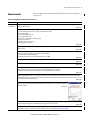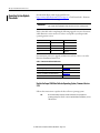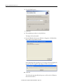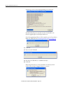
1
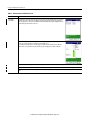
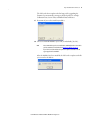
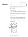
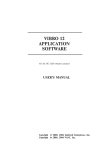
Release Notes
Enpac 2500 Data Collector Version 3.10
Catalog Number 1441-PEN25 and 1441-PEN25-Z
When to Use These Release
Notes
These release notes correspond to the Enpac® 2500 operating system update,
firmware revision 3.10.
The release notes provide the following information.
Topic
Page
Safety Information
2
Enhancements
3
Corrected Anomalies
7
Known Anomalies
11
Operating System Update Procedures
12
IMPORTANT
IMPORTANT
Use these Enpac 2500 operating system versions with the indicated Emonitor software
versions.
Enpac 2500 Operating System Version
Emonitor Software Version
3.10
3.5
3.0
3.4
2.0
3.3
1.03
3.2
If you send your Enpac 2500 data collector in for service, our service department will
upgrade the operating system to revision 3.10. Make sure you backup any of your data
before sending the unit for service.
2 Enpac 2500 Data Collector Version 3.10
Safety Information
Be aware of these safety precautions.
Avoid Water
IMPORTANT
The Enpac 2500 data collector is splash and dust resistant. However, avoid direct
contact with water, wet surfaces, or condensing humidity. Keep this instrument away
from wet locations, for example, laundry, wet basements, swimming pools.
If the data collector is subjected to these conditions, adverse operation may result.
Before you use it, let the instrument dry thoroughly before operating.
ATTENTION: To avoid damage or injury, place the Enpac 2500 data collector on a solid
stable surface when not in use and do not place any heavy objects on it. Use only the
accessories recommended by Rockwell Automation. Keep liquids and foreign objects
away from the instrument, and never operate it if any liquid or foreign object has
entered it.
Optical Ports
ATTENTION: When the laser on the data collector is active, viewing the laser beam can
expose your eyes beyond the maximum permissible exposure recommendations and
cause harm.
Laser Radiation Ports
ATTENTION: Class 1 laser product. Laser radiation is present when the system is open
and interlocks bypassed. Only trained and qualified personnel should be allowed to
install, replace, or service the instrument.
Rockwell Automation Publication GMSI10-RN004B-EN-E - August 2012
Enpac 2500 Data Collector Version 3.10 3
Enhancements
This section describes the new and updated software features provided in this
revision.
Table 1 - Enhancements with Revision 3.10
Cat. No.
Enhancement
1441-PEN25
1441-PEN25-Z
The Route Manager screen provides functions such as, Delete, Reset, and Open a Route. The screen displays the
routes you have loaded or have in internal memory.
On the Route Data Collection screen, a taken POINT count is shown in a caption bar, rather than showing a missed
POINT count below the Route hierarchy. The POINTS display in this format: Taken X of Y, where X is the number of
points taken and Y is the total number of points in the route.
The View Menu Options screen offers these settings:
• View selections
• Cursor mode
• Grid on/off
• Fill Sig on/off
The available settings change depending on the number of channels and the type of measurements you are taking.
Acquisition types have several View alternatives available, for example, with or without Overall bar. Fill Sig has moved from the Configuration menu to the
View Options. Cursor Mode option duplicates the functionality of the 4 (H) key when viewing spectra.
The frequency item labels are now drawn vertically alongside the active frequency item marker, previously shown above the signature plot.
Rockwell Automation Publication GMSI10-RN004B-EN-E - August 2012
4 Enpac 2500 Data Collector Version 3.10
Table 1 - Enhancements with Revision 3.10
Cat. No.
Enhancement
1441-PEN25
1441-PEN25-Z
The Addnl Measts option on the Enpac 2500 data collector has been replaced by the Multi-meas View on the Enpac
2500 data collector. This is where you select which measurements have signature shown. For measurements
where the Signature is not shown, the new Multi-measurement Summary table is displayed, filling in with each
overall reading as the measurement is collected.
A multi-line status bar appears in the display that avoids messages appearing over the signature trace. The status
bar uses color to show status: Green = taken, Red = taken in alarm or error.
The overall bar beside signature shows overall reading, for example, the power bar indicator in the Emonitor
software. Errors are reported in the status bar, and fewer pop-ups are displayed, for example, an ICP Error.
The speed entry for Orbit (untrig) or X-ch Phase is now integrated into the Main Collection screen; it’s not a pop-up.
Triggered Alarm Bands are listed in the status bar when collecting and reviewing data. This makes it easier to see which alarms are triggered.
The Enpac 2500 data collector, version 3.10 supports the Secure Digital High Capacity (SDHC) storage cards that are supported by the Microsoft Windows CE
driver.
Rockwell Automation Publication GMSI10-RN004B-EN-E - August 2012
Enpac 2500 Data Collector Version 3.10 5
Table 2 - Enhancements with the Enpac 2500 data collector, firmware revision 1.03…3.0
Operating
System Version
Enhancement
Description
3.0
Speed Storage
The Enpac 2500 can now save the cursor frequency value as speed. The 1XRPM that appears during data collection can be used to
set the machine speed based on cursor position. The cursor value is stored in the Machine Speed column of the Data History screen
in the Emonitor software.
Transducer Change
Notification
The Enpac 2500 data collector, revision 3.0 will display a warning message when moving between measurement points that are
configured for different sensors (like moving between acceleration and velocity measurements).
This function can be activated or deactivated through the Transducer Change parameter in the Setup utility screen.
Do not Warn = No message is displayed
Warn = Message is displayed when transducer is different than previous point
Nuclear Requirement:
Change Route Based
Sensor Calibration
This function was implemented to meet the requirements of most Nuclear facilities where the sensitivity used by the Enpac 2500
must be typed in exactly as marked on the sensor. This function gives the ability to change the sensitivity of sensors for route
based measurements.
IMPORTANT: If your facility does not require this function, then it is not recommended that it be used. Incorrect settings can affect
measurement results.
Print to SD Card
The Enpac 2500 data collector, revision 3.0, supports printing screen shots to the SD memory card.
Bias Check
The Enpac 2500 data collector, revision 3.0, gives two options to check the bias voltage before data collection. To configure Bias
Checking, select the desired setting in the Setup Utility.
Manual: To manually check the bias voltage by pressing the 0+2 keys simultaneously while in the data collection screen.
Automatic: Will automatically check and display the bias voltage for every point prior to data collection.
Speed Reference Point
This revision of the Enpac 2500 data collector has the ability to determine the speed using a frequency reference item in Emonitor
software. This allows for machine speeds to be stored and retrieved dynamically.
The speed reference can be configured as a manual entry or a tachometer (external or internal) and its value is used by the
frequency items to calculate the Fmax of the dependent measurements. The speed reference frequency is set up in the Frequency
Item pane in Emonitor.
Refer to the Enpac 2500 User Manual, publication GMSI10-UM002, for more information.
SD Memory Cards
The SD memory card has been added as an option to the Route Memory parameter in the Instrument Setup. You can use the SD
card to load and unload lists from Emonitor software.
The Enpac 2500 data collector supports up to 4 GB in size and 60X speed. The unit also supports a PCMCIA to SD converter.
Multiple Collection on a
Single Point
The Enpac 2500 data collector can now collect multiple readings for a single measurement point. The data collector can store up
to 10 additional measurements for the same measurement point. These additional measurements can be uploaded to your
database if so desired.
When you collect more than one spectrum for a point, the unit can display the spectrum in a waterfall plot. This enables you to
view several measurements in relationship to each other.
To support the multiple collection features, two new parameters have been added to the Instrument Setup – Hist. Data Collect
and Hist. Data Review. These parameters allow you to set up how the additional data will be stored and reviewed in the data
collector.
Diagnostic Frequency
Cursor
You can now use a special cursor to identify frequency items on a spectrum in the Enpac 2500. The frequency labels are
downloaded from Emonitor with your route. These diagnostic frequencies are the output items from the Frequency Items pane in
Emonitor.
Peak-Hold and
Exponential Averaging
Two additional averaging options are now supported – peak-hold and exponential averaging. You can use these averaging
options in your route and off route measurements.
Order Tracking
The Enpac now supports the specification and collection of a spectrum with an Fmax defined in terms of number of orders for a
varying machine speed.
Route Collection
Enhancement
The Enpac can now remember the last collection point taken prior to turning off the collector or exiting a route.
Review Data from Data
Collection Screen
The Review Data function is now available in the Data Collection screen. This allows you to review collected data within the route.
2.0
Date Added to Main Menu The date set in the Instrument Setup screen is now displayed on the Main Menu screen. This makes it easier to verify the date
before you start collecting data.
Rockwell Automation Publication GMSI10-RN004B-EN-E - August 2012
6 Enpac 2500 Data Collector Version 3.10
Table 2 - Enhancements with the Enpac 2500 data collector, firmware revision 1.03…3.0
Operating
System Version
Enhancement
Description
1.03
Improved Route
Navigation
A Navigation parameter has been added to the Setup screen that allows you to choose how you move through routes in the Data
Collection and Review Data screens. The following choices are available:
• Enpac - The unit displays a Selection screen when the RIGHT ARROW key is pressed in the Data Collection or Review Data
screen. The Selection screen allows you to select the item that you want to collect or review.
• DataPac - The unit functions like a Datapac® 1500 data collector in that it automatically advances to the next point (train,
machine, point) in the route when the RIGHT ARROW key is pressed in the Data Collection or Review Data screen.
Improved Review Data
Screen
Two new functions have been added to the Review Data screen: Offtour and View. These functions make it easier to review
previously collected route and off route data.
The Offtour button displays a list of off route measurements collected for the route. The Offtour function is present only if an off
route measurement is collected.
The View button displays the overall, FFT spectrum for the selected measurement. It is present only if data is available for the
selected measurement.
IMPORTANT: If the point has more than one measurement, you must press READ/OK to view the additional measurements. The
Next and Previous functions are no longer available on the Review Data screen.
New OffTour Review
Screen
The Off Tour Review screen displays a list of previously collected off route measurements. Click the Offtour button on the Review
Data screen to access the Off Tour Review screen.
Highlight the off route measurement you want to review and click View. The Enpac 2500 displays the Overall or FFT spectrum if it
is available.
IMPORTANT: If the point has more than one measurement, you must press READ/OK to view the additional measurements. The
Next and Previous functions are no longer available on the Review Data screen.
Support of Longer
Character Names
The Enpac 2500 supports up to 32-character names p7er hierarchy level. The Emonitor software supports the following character
lengths:
• Route - up to 16 characters
• Location - up to 16 characters
• Hierarchy - up to 32 characters
Support of Six Hierarchy
Levels
The Enpac 2500 data collector supports up to six hierarchy levels for each point. The hierarchy levels are defined by the structure of
the database in the Emonitor software. Refer to the Emonitor online help for assistance in setting up the hierarchy levels.
Rockwell Automation Publication GMSI10-RN004B-EN-E - August 2012
Enpac 2500 Data Collector Version 3.10 7
Corrected Anomalies
This sections describes the anomalies corrected by the Enpac 2500 data collector,
firmware revisions 1.03…3.10.
Table 3 - Corrected Anomalies with Firmware Revisions 1.03…3.10
Operating
System Version
Description
3.10
CORRECTED: In some instances, the Bump Test and Recorder modules just get an hour glass but does not go into the program.
CORRECTED: After incorrect installation, the Runup Coast Down module does not Show Setup menu.
CORRECTED: The -gSE Time waveforms can appear 'smoothed' when compared to the Datapac 1500 data collector.
CORRECTED: Overlapping band alarms do not trigger correctly.
CORRECTED: The Capture On Alarm only works with first point after the Magnitude point.
CORRECTED: Filtered Orbits support up to 3x filtering, all others will be taken and uploaded as Unfiltered.
CORRECTED: The 1x RPM does not update cursors when in Continuous mode.
CORRECTED: Occasionally gSE / Time measurements are not taken correctly (all 0s).
CORRECTED: The - gSE Time waveforms are inverted.
CORRECTED: The Alarm overwrites the RPM section of the status area.
CORRECTED: You can only review offroute orbits as orbits if the coupling is set to DC when collecting data.
CORRECTED: Hardware Integration (Time Only, or Conservative Autoranging) reads about 4-5% low.
CORRECTED: Speed control points auto advance.
CORRECTED: You can review offroute orbits only as orbits if the coupling is set to DC when collecting data.
CORRECTED: Add ability to either use smaller Font Size or remove 'wrapping' in the Hierarchy.
CORRECTED: When using the overlapping band set and an analog filter, the instrument may show dotted lines at the edges of the bands. You could see no
visible alarm level for any band for high alarms or a solid red from bottom to top of the spectrum for low alarm; it may not flash.
When using the overlapping band set and a digital filter, the instrument takes the overall first, and then a spectrum that shows the bands correctly, a solid color
up/down to the correct level and flashing if the level was exceeded.
You cannot see a flashing 'alarmed' band that is overlapped or nested if it is being covered up with a solid non-alarmed. You may also see all non-tripped
alarms in solid red, not shaded red or in the color associated with the alarm in the Emonitor software.
ICM00000789
CORRECTED: The Speed Reference function from a spectrum is not supported. The Current Spectrum Measurement and Extract from Current Spectrum
Measurement are also not supported by the Enpac 2500 data collector. Refer to speed reference in the Enpac 2500 User Manual, publication GMSI10-UM002.
ICM00000795
CORRECTED: The data collector does not recognize user defined units.
ICM00000755
CORRECTED: The data collector freezes when collecting data on a Secure Digital (SD) card for two continuous hours.
ICM00000760
CORRECTED: If no previous data is set with the Emonitor software configured as undefined for the speed reference, the instrument may not calculate speed
correctly for dependant points.
ICM00000785
ICM00000782
CORRECTED: The increase from 3 to 6 levels of hierarchy can make the navigation more complex due to the amount of data that must be scrolled through to
confirm the point.
ICM00000787
CORRECTED: When trying to set a high Fmax to measure gear mesh frequencies, for example, up to 80 kHz, the unit may let you take the reading if entering
with numeric keys.
ICM00000802
CORRECTED: When the route is collected, the first two channel measurement is collected without errors. During the second two channel measurement the
error message `error retrieving information from database’ appears and the route locks up.
ICM00000815
Rockwell Automation Publication GMSI10-RN004B-EN-E - August 2012
8 Enpac 2500 Data Collector Version 3.10
Table 3 - Corrected Anomalies with Firmware Revisions 1.03…3.10
Operating
System Version
Description
3.10
CORRECTED: After installing Enpac 2500 data collector revision 3 Hotfix 2, if you collect data on a measurement point and then try to delete the reading, the
instrument errors out TourDBException - cannot find signature tuple. Review the data and delete all the points individually.
ICM00000823
CORRECTED: When you load a magnitude/phase measurement point with a collection spec that has more that 8 orders and attempt to load to the collector, it
does not load the measurement point. The error message `Unsupported Measurement’.
ICM00000825
CORRECTED: The data collector cannot extract speed from spectrum if magnitude reading is taken first. To avoid this situation, create a Location ID with a
magnitude measurement point prior to a spectrum measurement point.
ICM00000834
CORRECTED: When taking a reading with the wrong filter selected, the OA Power Bar does not display when taking a reading.
ICM00000845
CORRECTED: Cannot unload multiple readings via USB connection from the Enpac 2500 data collector, revision 3.00 RC7, into the Emonitor software, version
3.40.33 with HF090525.
ICM00000846
CORRECTED: While in Route mode, the display listing of alarms and Band alarm status on the instrument needs to be improved.
The tabular listing of alarms are displayed on the Enpac 2500 data collector while in Route mode.
ICM00000847
CORRECTED: If you have band alarms that are overlapping then if one is triggered but the overlapping is not, you will not see the whole alarm band flashing
as the untriggered alarm is painted over the triggered one.
ICM00000848
CORRECTED: The frequency item order reference is not always the motor speed reference. Although the time waveforms have the correct speed for the motor
locations, the speed increased or reduced locations have an incorrect speed on just the waveforms. The ratio (multiply) relationship is not used, and the
waveform uses the motor speed for its rpm value. This affects only the Enpac 2500 data collector.
ICM00000849
CORRECTED: There is no power for accelerometer with velocity output when displaying reading in mils.
ICM00000850
CORRECTED: Options for printing to SD and Card is lost. the printing option is available in firmware revision 3.00 RC5 and is not available in firmware revision
3.00 RC7.
ICM00000861
CORRECTED: The data collector is unable to support DC Bias Trending in route mode when taking readings from a switch-box. These readings require the
instrument to power the transducer.
ICM00000862
CORRECTED: If a store/enter key is pressed before it starts the Initialize process, the unit locks up and must be warm booted. The lock-up unit during Power
Cycle, if Fire key is pressed before Splash Screen has completed.
ICM00000875
CORRECTED: Help off Main Menu has orage Ca as the button name.
ICM00000877
CORRECTED: The Balancing Extension Module defaults to External Trigger, a LASERTACH® option is needed.
ICM00000880
CORRECTED: When a motor is going slow, the rpm on the screen did not display the proper value. When changing speeds, the rpm did not change to match
the motor speed.
ICM00000882
CORRECTED: Overall (or Overall and Spec) points can get marked with wrong speed.
ICM00000924
CORRECTED: The data collector collects Unfiltered Orbits only, but not 1st Order, 2nd Order, for example, no filtered orbits.
ICM00000935
CORRECTED: Having a (Ov+Spec or RSS) Control Point which is it's own reference causes the point to not be taken.
ICM00000938
CORRECTED: When a machine is setup in Emonitor and using the Hz as a data collection point, manual entry, issues develops in the Enpac 2500. Amplitude
over time does not work across the screen. It becomes a straight line and the Enpac does not recognize the Hz on the screen.
ICM00000940
Rockwell Automation Publication GMSI10-RN004B-EN-E - August 2012
Enpac 2500 Data Collector Version 3.10 9
Table 3 - Corrected Anomalies with Firmware Revisions 1.03…3.10
Operating
System Version
Description
3.10
CORRECTED: Offroute does not take displacement from Accel in Time format.
ICM00000921
CORRECTED: Using SD Card, formatted as Fat32, you need to take 2 sets of data for the same route.
ICM00000933
CORRECTED: Further to the Orbit issue, there is another problem concerning Gap Voltage measurements from proximity probes.
The data collector always unloads a value of either -4.0882V when collected with an Orbit or -4.0868V when collected as a separate measurement. This is
regardless of the fact that the actual gap voltage is, for example, -9.987 or -10.023.
ICM00000936
3.0
CORRECTED: The data collector skipped measurement points with STD Envelope filters.
CORRECTED: The data collector inverted timewave forms. The cause was unique to specific measurement ordering.
CORRECTED: The data collector would not take GSE readings with user defined units.
CORRECTED: When reviewing data, the spectra plots would not be displayed.
CORRECTED: Frequency items would not load when loading routes through the RS232 cable.
CORRECTED: The data collector would not store data from temperature gun.
CORRECTED: The data collector would not turn on ICP power for measurements using velocity sensors. This would cause errors in resulting data.
CORRECTED: When applying notes to spectra, the data collector would “zero” out all amplitudes on the spectrum.
CORRECTED: If you have band alarms that are overlapping then if one is triggered but the overlapping is not, you will not see the whole alarm band flashing as
the untriggered alarm is painted over the triggered one.
ICM00000848
CORRECTED: gSE/Time measurements may not be taken correctly; the instrument has displayed all zeros when you follow this sequence.
• Restart the instrument.
• Take a gSE Time Only point.
ICM00000893
CORRECTED: When using a Velocity probe, both the data collector, revision 2.02, disables ICP power. When using OffRoute and coupling set to ICP, the unit
does not actually turn on ICP power.
ICM00000894
CORRECTED: If connected to a Speed Ref POINT, the Spectrum POINT is downloaded with the wrong speed value. This speed value is based on the previously
uploaded Speed. If this POINT is attached to a Speed Ref POINT, it should update to the newly measured speed and then upload to the Emonitor software with
the new value.
ICM00000895
CORRECTED: When you setup an OffRoute gSE POINT with Display Format = Time and 2 kHz filter, with 500 Hz Fmax, the gSE time waveforms are inverted. If
you apply a Burst signal, with a carrier of 1 kHz and Burst of 10 cycles and 50 ms (20 Hz), you may see that the spikes in the time waveform are going negative,
rather than positive.
ICM00000896
CORRECTED: The first time you delete a measurement (from Review) you get a TourDB error and it isn't deleted (although the tick mark vanishes), but if you
delete it again it disappears.
ICM00000897
CORRECTED: When taking an Orbit measurement, the default view shows the correct rpm. If you change to the Time View using the View Menu, then the
incorrect rpm is shown. The Orbit view is correct and is showing what is actually measured and stored.
ICM00000898
CORRECTED: If you take a measurement with Frequency Items where the Speed is taken from a previous POINT, for example rpm, then the Frequency Items are
incorrectly drawn in the FFT. They appear to get correctly drawn after the POINT has been stored, for example, they are correct in Review.
ICM00000899
CORRECTED: The Machine Speed 'Auto' setting should default to behave like 'Slow' when the associated rpm has less than 600 rpm. 'Auto' may only behave
like 'Slow' when the speed drops below 200 rpm, but this is too low (3.33 Hz).
ICM00000900
Rockwell Automation Publication GMSI10-RN004B-EN-E - August 2012
10 Enpac 2500 Data Collector Version 3.10
Table 3 - Corrected Anomalies with Firmware Revisions 1.03…3.10
Operating
System Version
Description
3.0
CORRECTED: When setting the following parameters OffRoute and applying a 60 Hz sine wave at 100 mV Pk with a -1V DC offset:
• Accel (g), DC Coupling, Peak Detection, Filter OFF, 400 Hz Fmax
You will get these results:
• Overall - 23.1 g
• 0 Hz bin - 20.1 g
• 60 Hz bin - 1 g
ICM00000901
CORRECTED: Orders-based measurements collect as if the Fmax is based on the speed downloaded from the Emonitor software, so changing the actual speed
does not change the Fmax used for the measurement.
ICM00000902
CORRECTED: Measurements are collected with the wrong Fmax for Orders points with speed set by a Control Point. If a point is set up as Orders but with the
speed coming from a Control Point, then (in many cases) the measurement is taken with the incorrect Fmax that makes the frequencies labeled incorrectly.
ICM00000903
CORRECTED: Downloading a route where the first point is unsupported and can give TourDB errors even though the invalid point is not downloaded and
require a soft restart.
ICM00000904
CORRECTED: If there is a point with a Magnitude and Spectrum collection, and you are using an Analog Filter, then it is possible for the Spectrum Peak to be
much larger than the Overall - especially if the measurement is Integrated.
ICM00000905
2.0
CORRECTED: The WinserDL download utility program did not correctly store the memory address labels in the registry.
CORRECTED: Intermittently the Enpac 2500 did not recognize the memory card.
CORRECTED: The data collector did not store the orbit measurements when the number of lines in the collection specification was greater than 400.
CORRECTED: Orbit readings taken from a Bentley Nevada panel did not display on the Enpac 2500 screen when you set the Auto Advance parameter to ON in
the Instrument Configuration screen.
CORRECTED: The data collector displays two time waveforms instead of an orbit plot when reviewing off route orbit data.
CORRECTED: Improved the data collection performance.
1.03
CORRECTED: The Enpac 2500 may choose an incorrect full-scale range when scaling the data for storage in the database.
CORRECTED: If the battery level was extremely low, the Enpac 2500 would not power off.
CORRECTED: The full scale does not adjust fast enough at the low frequencies range on slow moving machines with low amplitude levels (< .006 ips).
CORRECTED: For AC/DC panel measurements, the Enpac 2500 would apply a load to the panel if the DC bias is < -2 volts.
CORRECTED: The Enpac 2500 takes too long to settle when Trig Level is set to Auto and IEPE power is first applied to the instrument.
CORRECTED: Turning the Enpac 2500 off and on while viewing a route on the PCMCIA card would cause a tuple error.
Rockwell Automation Publication GMSI10-RN004B-EN-E - August 2012
Enpac 2500 Data Collector Version 3.10 11
Known Anomalies
These anomalies have been identified with the Enpac data collector, firmware
revision 3.10.
Table 4 - Known Anomalies with Firmware Revision 3.10
Cat. No.
Description
1441-PEN25
1441-PEN25-Z
The Enpac 2500 data collector does not store an Off Route Machine Name change. The name appears to changed but does not store the change. It reverts to
original name when unloading.
ICM00000767
The largest manual entry FSR that is supported by Enpac 2500 is 100,000.
If you need to manually enter values that are 7+ digits, do it in the Emonitor software.
From the Emonitor software:
1. Create a numeric manual entry point.
2. Load the route to the Enpac 2500.
3. Enter the value, 7 or more digits. For example, 33333333.
4. Press Enter to store the data.
5. On the Enpac 2500, go to review mode.
The FSR value appears as 33333333.0.
ICM00000784
If the ActiveSync software has a partnership during daylight savings time period, time on the data collector may not match the computer setting or programmed
instrument setting.
ICM00000827
The data collector produces incorrect speed measurements for the following:
• All foot per minute based equipment, as in paper mills or similar equipment.
• For any Hertz input variable speed equipment.
• Any time waveform that does not use the inputted speed reference as its RPM.
ICM00000832
Unit will load 12800 line TWF and appears to take reading. The measurement produces an error on the data collector followed by a corruption at download.
ICM00000839
Ft/Min speed reference does not display properly in the Emonitor software for either spectrum or TWF measurements.
ICM00000853
You have to press Enter instead of Fire in the transducer calibration screen. Inconsistently, it does not allow the Fire key to work in Sensor Calib menu.
The Enter and Fire keys are the same thing. There is inconsistent key naming throughout the documentation.
On the Bias Check screen, you must press the F2 (OK) button to continue, the Enter/Fire key does not work.
ICM00000870
The gSE TWF displays above/below zero. As a result, both the amplitude and offset are different than the Datapac values. Because gSE TWF tends to be
asymmetrical (typically with some more-or-less widely-spaced spikes), it is not always clear that this is happening. You may have the positive spikes sitting
much higher than the troughs go low. However, this is a display issue only. Any overall measurements are taken peak-to-peak so the presence or absence of the
DC offset should not affect overall measurements.
ICM00000876
The percentage change between last and current reading is displayed incorrectly when Chinese language is selected. This
happens while measuring and during reviewing taken measurements. The work around is to set the language to English and
retake the measurement.
ICM00000941
When taking an integrated measurement using the Conservative Autoranging setting, you may notice a measurement that is 15% lower than expected. To avoid
this lower reading, use the Aggressive or Fixed Autoranging setting to get consistently correct results.
ICM00000942
The help file includes references to the Dynamix User Manual, publication 1441-UM001.
Enpac 2500 data collector users should reference the Enpac 2500 Data Collector User Manual, publication GMSI10-UM002D-EN-E.
Rockwell Automation Publication GMSI10-RN004B-EN-E - August 2012
12 Enpac 2500 Data Collector Version 3.10
Operating System Update
Procedures
Download the Enpac 2500 .zip upgrade file from
http://www.rockwellautomation.com/support/. Click Downloads > Firmware
Updates > Condition Monitoring.
IMPORTANT
We recommend that you delete all older versions of the installer loader .msi files from
your computer before updating the Enpac 2500 data collector’s operating system.
Refer to this table when completing the following upgrade sections to determine
which Emonitor version and service release correspond to your Enpac 2500
operating system version.
Enpac 2500 Version
Emonitor Version
Service Release
3.10
3.5 Build 12
N/A
3.0
3.4
N/A
2.0
3.3
SR070628
1.03
3.2
SR060222
For instructions on how to upgrade you Emonitor software, refer to one of the
Emonitor Installation Instructions.
Table 5 - Emonitor Installation Publications
Publication
Publication Number
Emonitor Gupta Single User Installation Manual
EMONTR-IN001
Emonitor Gupta Multi User Installation Manual
EMONTR-IN002
Emonitor Oracle Multi User Installation Manual
EMONTR-IN003
Emonitor MSSQL Multi User Installation Manual
EMONTR-IN004
Update the Enpac 2500 Data Collector Operating System, Firmware Version
3.10
Follow these instructions to update the data collector operating system.
TIP
We recommend that you upload your data to Emonitor before you update the
operating system just in case there is an error with the firmware installation, such as a
cable disconnect.
Rockwell Automation Publication GMSI10-RN004B-EN-E - August 2012
Enpac 2500 Data Collector Version 3.10 13
Before performing the 3.10 firmware upgrade, take note of the modules installed
on the Enpac 2500 data collector.
TIP
To confirm which modules that are installed and the version by press F3 (About) on the
Main Screen.
Table 6 - Data Collector Modules
Cat. No.
Module
1441-PEN25-MOD-BAL
Balancing Upgrade
1441-PEN25-MOD-BMP
Bump Test
1441-PEN25-MOD-FRF
FRF - Frequency Response Function
1441-PEN25-MOD-RUCD
RuCD - RunUp CoastDown
1441-PEN25-MOD-REC
Recorder
Version
1. After downloading the Enpac 2500 3.10 Upgrade .zip file as instructed in
Operating System Update Procedures on page 12, follow these
instructions.
2. Connect your data collector to your computer by using the USB
connection.
3. Start Microsoft ActiveSync to be connected to the data collector.
4. Extract the .zip file.
5. Double-click the OS Loader.msi file.
Rockwell Automation Publication GMSI10-RN004B-EN-E - August 2012
14 Enpac 2500 Data Collector Version 3.10
6. Use the default location.
7. Click Next.
8. The installation procedure is ready, click Next.
The Enpac OS Loader installs.
9. From the Windows Start menu, click Start > Programs > Allen-Bradley >
Enpac2500 > Enpac2500 OS Loader.
At the beginning of the upgrade process, a message is shown saying that the
upgrade can take a long time, depending on the selections made.
10. Click OK.
The OS Loader automatically backs up any core files, such as Calibration
Data and License Files.
Rockwell Automation Publication GMSI10-RN004B-EN-E - August 2012
Enpac 2500 Data Collector Version 3.10 15
The option to Backup any Module Data, for example, Balance jobs or .wav
file recordings.
11. Decide if you need to backup data.
TIP
We recommend that you click yes to backup your data.
Next, you are given the option to backup any Routes.
TIP
We recommend that before you decide to backup any routes, upload your data to
Emonitor just in case there is an error with the firmware installation, such as a cable
disconnect.
12. Decide if you need to backup Routes.
After any requested backups have been completed, the OS Loader will
copy on the new NK.bin file and begin programming the new OS.
Rockwell Automation Publication GMSI10-RN004B-EN-E - August 2012
16 Enpac 2500 Data Collector Version 3.10
At this stage, you can see the OS programming occur on the unit.
Remember that this process can take some time. You should see the
firmware upgrade appear on the Enpac 2500 screen.
Once the programming of the new OS is complete, you need to perform a
Hard reset/Cold reboot. See Restarting the Data Collector on page 19.
13. Click OK.
14. Disconnect the USB cable.
15. Reconnect the USB cable to re-establish ActiveSync.
16. Click OK.
If ActiveSync hasn’t been reconnected within a few minutes, the OS
Loader will re-prompt for suggested ways to re-connect.
Rockwell Automation Publication GMSI10-RN004B-EN-E - August 2012
Enpac 2500 Data Collector Version 3.10 17
The OS Loader then completes the final stages of the upgrading the
Firmware, by automatically restoring any backed up files, for example,
Calibration Data, License Files, and Module Data and Routes.
17. Determine if you need to install any modules.
18. Choose to install All Modules (Yes to All) or individually (Yes/No).
TIP
We recommend that you select to install modules individually based on the modules
you have activations for listed in the table Data Collector Modules on page 13.
If you click Yes to All, the modules that you have not purchased activations for will
appear greyed and are unavailable.
After the Modules have been installed, the OS Loader completes and tells
you to wait for the Reboot.
Rockwell Automation Publication GMSI10-RN004B-EN-E - August 2012
18 Enpac 2500 Data Collector Version 3.10
Module Licensing
Any Modules that were licensed prior to the upgrade will still be licensed. Any
Modules that are installed, but which have not been licensed will appear greyed
out as unavailable.
To active greyed-out modules, contact your contact your local Allen-Bradley
distributor or Rockwell Automation sales representative. Use the table Data
Collector Modules on page 13 to identify what modules you need to order.
IMPORTANT
It will be necessary to re-enter the date and time in the Enpac 2500 data collector.
TIP
To confirm that the correct version was loaded, press F3 (About) on the Main
Screen. The firmware version should match the operating system file just loaded.
Rockwell Automation Publication GMSI10-RN004B-EN-E - August 2012
Enpac 2500 Data Collector Version 3.10 19
Restarting the Data
Collector
You should restart the Enpac 2500 data collector if the instrument locks up and
does not respond to any key presses including the On/Off key.
When you need to reset the data collector you can perform a hard or soft reset. A
hard reset resets the defaults vales of the date, time, and time zone. A soft reset
keeps the current values. A reset does not delete data or Routes.
Perform Soft Restart
When doing a soft restart, all files and programs present in memory remain in
memory following the restart.
TIP
Most of the time, a soft restart will reset any anomalies you are having
with the data collector.
With the data collector on, simultaneously hold down the 2, 7, 8, and 9 keys for
about a second. The data collector restarts and the Main Screen appears.
Perform Hard Restart
A hardware reset lets you to reconfigure the Enpac 2500 data collector back to
the factory default setup. Programs or data files stored in RAM are cleared, but
any programs or files stored in internal memory and any registry changes will be
maintained.
The reset switch is located behind the battery access panel on the underside of the
instrument. The reset switch can only by pressed using a 1/16- in diameter pin or
a straightened paper clip.
Reset Switch
Rockwell Automation Publication GMSI10-RN004B-EN-E - August 2012
20 Enpac 2500 Data Collector Version 3.10
Follow these steps to replace the battery.
1. Using a flat head screwdriver, remove the two latch screws on the battery
access panel.
2. Remove the battery access panel.
3. Press the Reset button using a 1/16th inch diameter pin or a straightened
paper clip.
4. Replace the battery access panel and tighten the two screws.
The Enpac 2500 data collector automatically powers on.
Allow at least thirty seconds for the instrument to reconfigure and activate the
display after the Instrument Setup screen appears.
IMPORTANT
The current date, time and some status information will be lost, and
the backlight setting will be returned to the default setting following a
hardware reset.
See the Enpac 2500 User Manual, publication GMSI10-UM002 for
information about setting the date and time.
IMPORTANT
Additional Resources
Any data held in internal memory is secure and will not be lost nor
destroyed during a hardware reset.
These documents contain additional information concerning related products
from Rockwell Automation.
Publication
Description
Enpac 2500 User Manual, publication GMSI10-UM002
Provides information about how to use the Enpac 2500
data collector.
Industrial Automation Wiring and Grounding Guidelines,
publication 1770-4.1
Describes the general guidelines for installing a Rockwell
Automation® industrial system.
Product Certifications website, http://www.ab.com
Provides the declarations of conformity, certificates, and
other certification details.
You can view or download publications at
http://www.rockwellautomation.com/literature/. To order paper copies of
technical documentation, contact your local Allen-Bradley distributor or
Rockwell Automation sales representative.
Rockwell Automation Publication GMSI10-RN004B-EN-E - August 2012
Enpac 2500 Data Collector Version 3.10 21
Notes:
Rockwell Automation Publication GMSI10-RN004B-EN-E - August 2012
Rockwell Automation Support
Rockwell Automation provides technical information on the Web to assist you in using its products.
At http://www.rockwellautomation.com/support, you can find technical manuals, technical and application notes, sample
code and links to software service packs, and a MySupport feature that you can customize to make the best use of these
tools. You can also visit our Knowledgebase at http://www.rockwellautomation.com/knowledgebase for FAQs, technical
information, support chat and forums, software updates, and to sign up for product notification updates.
For an additional level of technical phone support for installation, configuration, and troubleshooting, we offer
TechConnectSM support programs. For more information, contact your local distributor or Rockwell Automation
representative, or visit http://www.rockwellautomation.com/support/.
Installation Assistance
If you experience a problem within the first 24 hours of installation, review the information that is contained in this
manual. You can contact Customer Support for initial help in getting your product up and running.
United States or Canada
1.440.646.3434
Outside United States or Canada
Use the Worldwide Locator at http://www.rockwellautomation.com/support/americas/phone_en.html, or contact your local Rockwell
Automation representative.
New Product Satisfaction Return
Rockwell Automation tests all of its products to ensure that they are fully operational when shipped from the
manufacturing facility. However, if your product is not functioning and needs to be returned, follow these procedures.
United States
Contact your distributor. You must provide a Customer Support case number (call the phone number above to obtain one) to your
distributor to complete the return process.
Outside United States
Please contact your local Rockwell Automation representative for the return procedure.
Documentation Feedback
Your comments will help us serve your documentation needs better. If you have any suggestions on how to improve this
document, complete this form, publication RA-DU002, available at http://www.rockwellautomation.com/literature/.
Allen-Bradley, Rockwell Software, Rockwell Automation, Enpac, Emonitor, Dynamix, Datapac, LASERTACH, and TechConnect are trademarks of Rockwell Automation, Inc.
Trademarks not belonging to Rockwell Automation are property of their respective companies.
Publication GMSI10-RN004B-EN-E - August 2012
Supersedes Publication GMSI10-RN004A-EN-E - October 2007
PN-135436
Copyright © 2012 Rockwell Automation, Inc. All rights reserved. Printed in the U.S.A.