1
SWARCO TRAFFIC SYSTEMS GMBH
In the manual you will find important instructions helping
you to avoid danger and to prolong the reliability and durability of the device and the accessories.
For your own safety you should read the safety instructions. Follow the instructions closely in order to avoid danger for yourself and others or damage to the device.
IG325/2
User manual
If you have any questions about the IG325/2, which are
not answered in this manual, or if you have problems understanding the descriptions, please contact:
1 Introduction
On the following pages you will learn how to install and
operate the device in an appropriate way. We attach great
importance to the safe, appropriate and effective handling
of this device. It is therefore important to read this manual
thoroughly before using the device.
© 2010 All rights reserved
IG325_2_BE_20
ATTENTION!
Danger of electricity! Make sure that no liquid may get
inside the device. If this happens, interrupt the power
supply to the device at once.
If you notice any damage, e.g. broken or crushed cables,
damaged plugs, enclosures etc., turn off the device at
once, interrupt the power supply and make sure that the
device cannot accidentally be turned on again.
The device may only be installed, brought into service and
repaired by an electro-technical expert. Inappropriate
operation, improper maintenance or not observing the
instructions in this manual can lead to danger.
Any malfunction of the device which may limit the safety
of its users or others must be removed immediately. All
warning and safety labels on the device must be observed
and kept complete and legible.
The appropriate usage must be observed by all means.
For damage resulting from inappropriate usage the manufacturer will not undertake any liability.
The device must not be used as a safety component in the
sense of the European Directive 98/37/EC ("Machinery Directive”). In systems with high risk additional safety measures are necessary.
2 Product description
Before installation and first operation, please observe the
instructions in the manual.
The manual must be available at the site of usage at any
time. It must be read thoroughly and applied appropriately
by the person responsible for the operation, maintenance
and service of the device.
Note
Our products are in a constant process of improvement
and advancement. Because of this, read the current manual thoroughly before installation and first operation.
Without prior consent of the manufacturer, no modifications, neither mechanical nor electrical, may be done.
Only parts that have the consent of the manufacturer may
be used for backfitting or as accessories. Any violations
will lead to the termination of conformity and the manufacturer’s warranty. The user will subsequently bear the
risk (the Declaration of Conformity is available at
www.swarco.com/sts).
Output
IG325/2 S.T. /
IG325/2 S.V. /
IG325/2 W.T. /
IG325/2 W.V. /
IG325/2 ST.T.
IG325/2 ST.V.
7 levels adjustable per channel adjustfrom High 0.01 to able in 4 levels from
Low 0.9
High 0.01 to Low 0.9
(adjustment of frequency in %)
impulse mode 100
per channel in
ms (optional 1 s)
4 levels adjustable:
and static hold time 0.1 s; 4.5 min; 2 h;
automatically after switch-on of power
supply, after pushing reset switch
floating relay contact
Umax = 250 V, Imax = 2 A,
Pmax = 60 W (ohm resistive load)
LED red = loop failure,
LED green = detection,
LED yellow = blinking when
alignment / power
galvanic separation by transmitter,
glow lamp
Hold time
Alignment
Technical data
Displays
Safety circuit
loop input
7
Measurements
are subject to
manufacturer’s
tolerances!
37
8
Loop 1
75
79
Loop 2
8
7
9
10
5 Channel1
11
3 Channel2
6
4
2
UN
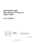
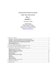
N.C. = not connected
UN = power supply device *
Contact position: Detector on, loop not occupied
* indicated on right label of device
1
Special model
325/2 SV / ST *
Loop 1
89
68
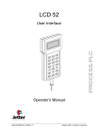
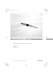
240 g
Standard model 325/2 WV /WT *
7 11
6
5
Channel1
3
Channel2
2
UN
9 = N.C.
28
9
325/2 STV / STT *
Loop 1
Loop 2
8
4
2.5 Dimensions
(in mm)
15 µH to 2000 µH (see also 6.1),
recommended range:
100 µH to 300 µH at max. 30
2.2 Switching outputs
The switching outputs are coupled with the LED display
(channel1: A; channel2: H) on the front panel (see 4). For
each channel there is one switching output available, for
which the status “loop occupied” can be switched (channel1 – channel2). The special models STV resp. STT have
one further switching output for the fault reports (ERROR),
which are activated when at least one channel is faulty.
All switching outputs are equipped with electro-mechanical
relays.
2.6 Pin connection
Technical data
dimension of socket manufacturer-dependent
2.1 Features
The induction impulse transmitters IG325/2 evaluate the
loops in the ground. Those depict the inductivity of a highfrequency oscillator circuit. If a vehicle crosses the loop,
its metal components cause a change of frequency in the
oscillator circuit. These are analysed by the loop detector,
transmitted as switching signals via floating relay contacts
and displayed on the front LEDs. The analysis of the loop
frequency is done via a micro-processor system which
aligns automatically to the according loop and compensates changes of the loop inductivity caused by temperature, humidity or aging of components.
The 2-channel induction impulse transmitter IG325/2
analyses two loops in multiplex process. Since only one
loop at a time is active, interference is avoided even when
loops are interlaced.
6
2.4 Technical data
Weight
Inductivity range
1.5 Safety instructions
Read the following safety instructions thoroughly and observe them carefully. They are stated to ensure your own
safety and the safety of others and to avoid damage to the
device or accessories.
The operator of the device must ensure that the chosen
means of operation will not cause damage to material or
danger to people and that all security and safety installations are present and functioning.
Sensitivity
adjustable
per channel
Operating temperature
Storage temperature
Safety
Enclosure (plastic)
Connection
Note
This symbol indicates information for installation and
function of the device.
3
2.3 Parameter adjustment
Via the DIP-switches on the front the following parameters
can be adjusted:
sensitivity
hold time
frequency of the measuring system
switch-off delay
directional logic
impulse when leaving the loop
switch-on delay
automatic alignment
detection by fault
Power supply
ATTENTION!
This symbol indicates dangers which might cause damage
to people or property.
2
5
IG325/2 S.T. /
IG325/2 S.V. /
IG325/2 W.T. /
IG325/2 W.V. /
IG325/2 ST.T.
IG325/2 ST.V.
230 V AC: (-10 - +6) % / 4,5 VA
(50 Hz: +/-0,5 %)
resp. 24 V AC/DC: +/-10 % / 3 VA
-25C to +70C
-40C to +80C
IP30
l = 75 mm, w = 37 mm, h = 68 mm
via 11-pin connector (type 78-S 11);
________________________________________
CE-label:
71
4
1.2 Label
The IG325/2 is provided with a quality label / serial number. You will need these indications when talking with the
customer service, e.g. ordering accessories or spare
parts.
Socket
1
________________________________________
Voltage version:
1.4 Symbols
In several places throughout this manual you will find the
following symbols stating important safety instructions:
1.1 Usage according to regulations
The IG325/2 is solely suited for the detection of vehicles.
Any further usage is not appropriate. Do not use the
IG325/2 for any other purpose.
www.swarco.com/sts
Serial number:
1.3 Further documentation
Notes on loop installation
SWARCO TRAFFIC SYSTEMS GMBH
Business Unit Detection
Niederkircher Straße 16
D-54294 Trier
[email protected]
Subject to technical modifications.
Note here the serial number and name of the device in order to have them available when needed:
1
10
8
7
6
9
5 Chanel1
4
3 Channel2
10
2
Loop 2
11 fault report
UN
1
3 Installation of the IG325/2
For the use of the device in a surrounding with higher
protection requirements, SWARCO TRAFFIC SYSTEMS
offers special enclosures (type GHIG300 / GHIG301).
Before switching on the power supply, the device must be
plugged onto the socket.
3.1 Special notes on the loop
The safe functioning of the device depends essentially on
the technically proper installation and laying of the loops,
since the loops are the sensors of the device. The loop
feed cable must be drilled approx. 20 – 50 times per meter
and must be laid in distance from life wires. For further information see “Laying of Loops” (available at
www.swarco.com/sts).
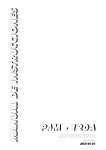
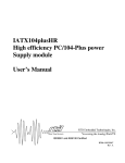
4 Device adjustments
A
After every device adjustment
a new alignment must be effected
by pushing the reset-button (E).
B
G
C
I
H
D
F
4.3 Function selection switch (D)
Switch 3 on
Impulse when
leaving the loop
active
Switch 4 on
Switch-on delay
on
Switch 5 on
Automatic
alignment
active when
fault
The switching signal is switched-off with a delay
of 2 seconds after the loop is vacant (not in impulse mode).
The attenuation of the first loop is registered in
the detector but no relay is switched yet. Only if
the second loop is attenuated at the same time,
the relay of the channel which was attenuated
the last is switched and stays switched until the
second loop is clear again. This function is valid
for both directions.
The detector switches the channel-relay only after the loop is vacant. The adjustment is only
active if additionally the channel status impulse
mode (channel switch (C) S4, S8) is chosen.
The switching signal is emitted when the loop is
attenuated for more than one second.
When there is a loop fault, the detector aligns
anew automatically after approx. 12 seconds. If
the fault lasts for a longer period of time, the detector keeps trying to align until the fault is
eliminated. The relays and LEDs stay in “fault”
position until the alignment is effected.
Switch 6 on A loop fault is indicated on the LEDs and addionally the according channel relay is switched
Detection by
on. For a combination with switch 6 on, switch 5
fault active
must by all means rest on off, since otherwise
the detector aligns anew after 12 seconds and a
vehicle which might stand on the loop will not be
detected anymore.
13
Description
Possible
cause
Vehicle movement on the
loop
Loop is moved
mechanically
Correction
Keep loop clear during
alignment
Control laying of loop,
observe documentation
“Laying of loops“
ElectromagEliminate cause of counetic coupling pling, observe documenonto the loop tation “Laying of loops“
Yellow LED continuously blinking
After every change of adjustment resp. correction of
error the reset button (E) must be pushed!
6 EC Conformity
6.1 Requirements for the usage according
to regulations
Requirements acc. to ETSI EN 300330-1 (2002-12)
For the antenna factor (loop area A in m2 multiplied by
the number of loop windings N) the following is
imperative: N*A ≤ 60 m2
Product Class 2:
Maximum length /
width
Area
Number windings
16
IG325/2 Version „Tor“ (gate)
(Type: IG325/2S.T. / IG325/2W.T. / IG325/2ST.T.)*
* indicated on right label of device
channel
switch (C)
sensitivity
channel1
channel2
7 (high)
6
5
4 (med)
3
2
1 (low)
S5 S6 S7 hold time: S8
S1 S2 S3
S4
on on on on=impulse / off=static
off on on
‘’
on off on
‘’
off off on
‘’
on on off
‘’
off on off
‘’
on off off
‘’
test mode relay released
off off off
off
test mode relay released
off off off
on
default setting: sensitivity 4 (med) and static hold time.
sensitivity:
channel 1
channel 2
adjustable in 7 levels channel switch (C) channel switch (C)
S5-S7
S1-S3
hold time:
static (presence)
or impulse 100 ms
channel 1
channel 2
channel switch (C) channel switch (C)
S8
S4
IG325/2 Version „Verkehr“ (traffic)
(Typ: IG325/2S.V. / IG325/2W.V. / IG325/2ST.V.)*
* indicated on right label of device
channel
switch (C)
sensitivity
channel1
channel2
4 (high)
3
2
1 (low)
S5
S1
on
off
on
off
S6
S2
on
on
off
off
S7
S3
on
off
on
off
off off
off
off off
off
default setting: sensitivity 3 and 2h hold time.
test mode relay released
test mode relay released
channel 2
channel switch (C)
S1-S2
hold time:
channel 1
adjustable in 4 levels channel switch
(C) S7 - S8
channel 2
channel switch (C)
S3 - S4
4.2 Adjustment of frequency
with the frequency switch (G) S1-S2 in order to avoid couplings caused by nearby loops. Two or more detectors
must not operate on the same frequency.
11
5 Alignment and fault diagnosis
5.2 Detection and correction of errors
5.1 Alignment
When switching on the power supply, when there are voltage interruptions or when the reset switch (E) is pushed,
the loop detector automatically aligns itself to the connected loops and switches the relays to switching position
“loop not attenuated”. During the alignment period the
yellow power-LED (F) is blinking for a few seconds. With
a low sensitivity the detector is ready for operation at
once. After the alignment the power-LED (F) keeps glowing.
During the alignment phase there may be no
vehicle on the loop since it will not be detected.
Display of switching and failure status
The switching mode “loop occupied“ is indicated by a
glowing green channel-LED (A) resp. (H).
Loop failure caused by a short-circuit, an interruption or a
loop inductivity outside of the permitted range is indicated
by a glowing red channel-LED (B) resp. (I).
S1
left*
right*
left*
right*
S2
left* *position of switches
left* (see also front panel)
right*
right* default setting: 4 (high)
Description
Possible
cause
Detector does not There is no
align, yellow LED power supply
does not glow
for detector
Red LED glowing, Detector
green LED blinking detects “loop
long, long, long
interrupted“
Red LED glowing, Detector
green LED blinking detects “loop
short, long, short short-circuited”
Test mode
Yellow and green relay tightened
is active
LEDs glowing,
relay permanently Loop is moved
tightened
mechanically
Correction
Check connection to
power supply
Check loop and loop
connection
Check loop and loop
connection
Deactivate test mode
(see table Adjustment of
sensitivity and hold time)
Control laying of loop,
observe documentation
“Laying of loops“
Test mode re- Deactivate test mode
lay released is (see table Adjustment of
Detector does not active
sensitivity and hold time)
switch in spite of
Progressively increase
effected alignment Chosen
sensitivity is
sensitivity until vehicles
too low
are detected correctly
14
15
Constraints for the compliance with EN 300330-1
According to the stated formula, the following loop windings in dependence to the loop area are recommended:
6.2 EC Declaration of Conformity
Product Class acc.
Number
Area
to EN 300300-1
windings
2
(1 – 3) m2
6
2
(3 – 5) m
5
2
(5 – 10) m
4
2
(10 – 15) m
3
2
(15 – 30) m
2
2
3
(30 – 60) m
1
Lloop [µH]
100 - 300
80 – 260
160 – 320
180 – 280
80 – 180
40 - 100
Operating frequency range (L = 15 µH – 400 µH)
20.05 kHz < f < 70 kHz
Total inductivity (loop + feed cable):
Specification: Ltotal< 400 µH
Example:
Loop inductivity 200 µH; feed cable inductivity < 200 µH
with 100 µH / 100 m: length of feed cable < 200 m
Requirements acc. to DIN EN 60950
The device has basic insulation.
Product Class 3:
30 m
< 30 m2
≥1
Area
Number windings
> 30 m2
1
© 2010 All rights reserved
17
S8 hold time
S4
on
0.1s
on 4.5min.
off
2h
off
off
on
sensitivity:
channel 1
adjustable in 4 levels channel switch
(C) S5-S6
frequency
switch (G)
frequency 4 (high)
3
2
1 (low)
12
E
10
Switch 1 on
Switch-off delay
on
Switch 2 on
Directional logic
active
4.1 Adjustment of sensitivity and hold time
18