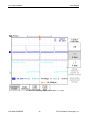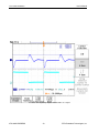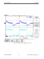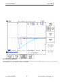
1
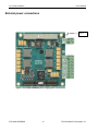
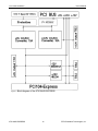
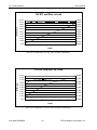
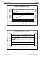
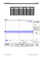
ATX104HR-EXPRESS High Efficiency PCI/104-Express Power Supply Module User’s Manual BDM-610020070 Rev. G User’s Manual ATX104HR-EXPRESS ATX104HR-EXPRESS Power supply module User’s Manual RTD Embedded Technologies, Inc. 103 Innovation Blvd. State College, PA 16803-0906 Phone: +1-814-234-8087 FAX: +1-814-234-5218 E-mail [email protected] [email protected] web site http://www.rtd.com ATX104HR-EXPRESS 2 RTD Embedded Technologies, Inc. User’s Manual ATX104HR-EXPRESS Revision History Rev A Rev B Initial Release 02/20/2009 Corrected typos (changed PC/104+ to PC/104-Express) Rev C 10/06/2011 changed name of power output connector, added X2, added surge suppressor, corrected Graphics Rev D Corrected explanation of X2 jumper in Connector Descriptions Rev E 11/12/2014 Corrected X1-X2 operation table Rev F 11/18/2014 Added information about identifying pin one on X1 Rev G 05/18/2015 Added MTBF Published by: RTD Embedded Technologies, Inc. 103 Innovation Blvd. State College, PA 16803-0906 Copyright 1999, 2002, 2003 2004 by RTD Embedded Technologies, Inc. All rights reserved Printed in U.S.A. ATX104HR-EXPRESS 3 RTD Embedded Technologies, Inc. User’s Manual ATX104HR-EXPRESS The RTD Logo is a registered trademark of RTD Embedded Technologies. cpuModule and utilityModule are trademarks of RTD Embedded Technologies. PC/XT, PC/AT and IBM are trademarks of International Business Machines Inc. MS-DOS, Windows, Windows 95, Windows 98 and Windows NT are trademarks of Microsoft Corp. PC/104 is a registered trademark of PC/104 Consortium. All other trademarks appearing in this document are the property of their respective owners. ATX104HR-EXPRESS 4 RTD Embedded Technologies, Inc. User’s Manual ATX104HR-EXPRESS Table of Contents CHAPTER 1 INTRODUCTION ..................................................................................... 8 Features........................................................................................................................................................................ 8 Power Supply Unit Description.................................................................................................................................. 8 Mechanical description ............................................................................................................................................... 9 Connector description................................................................................................................................................. 9 What comes with your board? ................................................................................................................................. 10 Using this manual ...................................................................................................................................................... 10 When you need help .................................................................................................................................................. 10 CHAPTER 2 BOARD INSTALLATION ...................................................................... 11 Board installation ...................................................................................................................................................... 11 General installation guidelines: ........................................................................................................................... 11 Installation integrated with a PC/104-EXPRESS module stack: ......................................................................... 12 External power connections ..................................................................................................................................... 13 Connector Descriptions: ........................................................................................................................................... 14 CHAPTER 3 - HARDWARE DESCRIPTION .............................................................. 15 Main +5V and +3.3V converter for the computer .................................................................................................. 17 Current Limit....................................................................................................................................................... 17 Remote On/Off control........................................................................................................................................ 17 Secondary +12V and -12V converters ..................................................................................................................... 18 Onboard status LED’s ......................................................................................................................................... 18 Overload protection ............................................................................................................................................ 18 CHAPTER 4 ATX104HR-EXPRESS SPECIFICATIONS ........................................... 20 Host interface ............................................................................................................................................................ 20 Power supply specifications...................................................................................................................................... 20 Input voltage range .............................................................................................................................................. 20 Output Power (88W total ) .................................................................................................................................. 20 Efficiencies.......................................................................................................................................................... 20 Maximum Board Power dissipation (worst conditions) ...................................................................................... 20 Output voltage regulation .................................................................................................................................... 20 Electromechanical ............................................................................................................................................... 21 Electrical Characterization: ................................................................................................................................. 22 CHAPTER 5 RETURN POLICY AND WARRANTY ................................................... 36 Return Policy ............................................................................................................................................................. 36 CHAPTER 6 LIMITED WARRANTY .......................................................................... 38 CHAPTER 7 ATX104HRTX-EXPRESS-88W DIMENSIONED DRAWING ................ 39 CHAPTER 8 IDAN-ATX104HRTX-EXPRESS-88WS DRAWING AND PINOUTS ..... 40 ATX104HR-EXPRESS 5 RTD Embedded Technologies, Inc. User’s Manual ATX104HR-EXPRESS Figure 1: Pheonix Contact 1781043 Figure 2: Phoenix Contact 1779987 Figure 3: ATX104HR-EXPRESS powering an RTD PC/104-EXPRESS cpuModule stack. PCI bus shown with non-stack through connector. Standard is press fit stack through. Figure 4: ATX104HR-EXPRESS power supply power connections Figure 5: Block diagram of the ATX104HR-EXPRESS Figure 6: Dimensioned Drawing ATX104HR-EXPRESS 6 RTD Embedded Technologies, Inc. 9 9 12 13 16 39 User’s Manual ATX104HR-EXPRESS ATX104HR-EXPRESS 7 RTD Embedded Technologies, Inc. User’s Manual ATX104HR-EXPRESS Chapter 1 INTRODUCTION This user’s manual describes the operation of the ATX104HR-EXPRESS power supply unit for automotive and industrial applications. Features Some of the key features of the ATX104HR-EXPRESS include: Wide input voltage range 8-32 V DC (36V absolute max) No heat sink required with natural convection cooling up to 45˚C, 83W total output power guaranteed with adequate cooling, Up to 91 %efficiency at full load Dual phase construction to minimize input ripple current and improve step response Synchronized supplies to reduce switching stresses Remote ON/OFF operation ATX104HR-EXPRESS outputs +3.3V, +5V, +12V, -12V, 5V STDBY Four status LED's Fully PC/104-EXPRESS compliant Operating temperature range -40 to +85 C The following paragraphs briefly describe the major features of the ATX104HREXPRESS. A more detailed discussion is included in Chapter 3 (Hardware description). The board installation is described in Chapter 2 (Board Installation). Power Supply Unit Description The ATX104HR-EXPRESS power supply unit offers a complete reliable power subsystem for your sophisticated computer and peripherals. To improve reliability in harsh environments, the ATX104HR-EXPRESS is designed using protection devices against over voltages, noise spikes and reverse input voltage. The output current of the +5V and the +3.3V converter is limited to 10A. These features allow reliable system operation in distributed industrial installations. A 5V STDBY supply, capable of 1A, is present so ATX compliant systems can be built on this board. ATX support signals PS_ON# and PWR_ON allow software controlled shutdown and power monitoring available for your CPU. The +5V and the +3.3V computer power supplies are designed using high efficiency switching regulators providing high output current (10A) with efficiency as high as (91 %) under all conditions. The secondary peripheral power supplies are designed using +12V and -12V converters that are supplied by the +5V DC/DC converter. Low component count and extensive use of SMD technology ensures low weight and reliable operation. Special care has been taken to reduce radiated and conducted emissions. Optimized ATX104HR-EXPRESS 8 RTD Embedded Technologies, Inc. User’s Manual ATX104HR-EXPRESS multi-phase circuit layout ensures good EMI immunity over the operating temperature range under all loads. The ATX104HR-EXPRESS can be “switched off” from a remote source. If this switch (jumper X1) is on pins 2-3 the power supply will become inactive while still powered. Mechanical description The ATX104HR-EXPRESS is designed on a PC/104-EXPRESS form factor. An easy mechanical interface to both PC/104-EXPRESS and EBX systems can be achieved. Stack your ATX104HR-EXPRESS directly on a PC/104-EXPRESS compliant computer using the onboard mounting holes. Care must be taken to ensure adequate heat dissipation from the board in high output power installations. Connector description The power connections are made using "cable plug" type terminal blocks. This enables removing connections from the board without removing the cables from the terminal blocks. The IDAN-ATX104HR-EXPRESS boards always feature screw terminal blocks for inter-frame wiring. The mating connector for the standard version is the Pheonix Contact 1781043 (eight position plug). There is also a Pheonix Contact 1779987 (two position plug). Figure 1: Pheonix Contact 1781043 Figure 2: Phoenix Contact 1779987 ATX104HR-EXPRESS 9 RTD Embedded Technologies, Inc. User’s Manual ATX104HR-EXPRESS What comes with your board? Your ATX104HR-EXPRESS package contains the following items: ATX104HR-EXPRESS board with mating connectors for power connections User's manual If any item is missing or damaged, please call RTD Embedded Technologies, Inc. customer service department at the following number: (814) 234-8087. Using this manual This manual is intended to help you install your new ATX104HR-EXPRESS module and get it working quickly, while also providing enough detail about the board and its functions so that you can enjoy maximum use of its features even in the most demanding applications. When you need help This manual will provide you with enough information to fully utilize all the features on this board. If you have any problems installing or using this board, contact our Technical Support Department (814) 234-8087. Alternatively, send a FAX to (814) 234-5218 or Email to [email protected]. When sending a FAX or Email request please include the following information: Your company's name and address, your name, your telephone number, and a brief description of your questions. ATX104HR-EXPRESS 10 RTD Embedded Technologies, Inc. User’s Manual ATX104HR-EXPRESS Chapter 2 BOARD INSTALLATION The ATX104HR-EXPRESS power supply module is very easy to connect to your industrial or automotive control system. Direct interface to PC/104-EXPRESS systems as well as EBX size boards is achieved. This chapter tells you step-by-step how to install your ATX104HR-EXPRESS into your system. Board installation Keep your board in its antistatic bag until you are ready to install it to your system! When removing it from the bag, hold the board at the edges and do not touch the components or connectors. Please handle the board in an antistatic environment and use a grounded workbench for testing and handling of your hardware. Before installing the board in your computer, check the power cabling. Failure to do so may cause the power supply unit to malfunction or even cause permanent damage. General installation guidelines: Touch the grounded metal housing of your computer to discharge any antistatic buildup and then remove the board from its antistatic bag. Hold the board by the edges and install it in an enclosure or place it on the table on an antistatic surface. Install your board in your system, and wire the power supply correctly. Failure to do so may cause the power supply unit to malfunction or even cause permanent damage to the device. Check all wiring connections once and then once more again. Check the input power to the board is in the range of 8 to 36V DC Apply power to your ATX104HR-EXPRESS, and make sure the diagnostic LED’s indicate correct operation. ATX104HR-EXPRESS 11 RTD Embedded Technologies, Inc. User’s Manual ATX104HR-EXPRESS Installation integrated with a PC/104-EXPRESS module stack: Secure the four PC/104-EXPRESS installation holes with standoffs. Connect the board to the power supply using the power interface connectors. Figure 3: ATX104HR-EXPRESS powering an RTD PC/104-EXPRESS cpuModule stack. PCI bus shown with non-stack through connector. Standard is press fit stack through. ATX104HR-EXPRESS 12 RTD Embedded Technologies, Inc. User’s Manual ATX104HR-EXPRESS External power connections Pin 1 Figure 4: ATX104HR-EXPRESS power supply power connections ATX104HR-EXPRESS 13 RTD Embedded Technologies, Inc. User’s Manual ATX104HR-EXPRESS Connector Descriptions: TB1: Raw input power to the ATX104HR-EXPRESS, voltage range is 8-32 V (36V absolute max) DC. Surge suppressor with 36V clamp voltage followed by transient absorber with cutoff at 39V DC. Note: The module input power may be up to 100 W, this will require AWG 16 wire (1.14mm2)(Make sure this input wire is kept as short as possible to reduce voltage drops (0.005/foot) and inductive spikes (513 nH/foot). Also wrap the input leads at least once every 2 inches to reduce loop inductance. TB2 : TB2 : TB2: TB2 : X1 : +5V Output of the main DC/DC power supply +3.3V Output of the main DC/DC power supply -12V Output +12V Output Remote ON/OFF , close this jumper in the pin 1 to 2 position to disable the 5V STDBY X1-X2 operations. (highlighted cells are ATX functionality) X2=installed X2=open X1=1-2 5V=off 12V=off -12V=off 3.3V=off 5Vstby=off 5V=off 12V=off -12V=off 3.3V=off 5Vstby=off X1=2-3 5V=on 12V=on -12V=on 3.3V=on 5Vstby=on 5V=off 12V=off -12V=off 3.3V=off 5Vstby=on X2: PS_ON# signal. Short to enable all voltages except for 5V STDBY CN1: PCI express bus CN3: PCI bus The output voltages are also indicated on the silk-screen on the bottom side of the module under the terminal blocks. Check these before making any external power connections. The input of the ATX104HR-EXPRESS is protected against reverse voltages, but will not withstand long term overvoltage. The transient absorbers will clip all fast disturbance and noise on the input, but may overheat if continuous overvoltage is present. ATX104HR-EXPRESS 14 RTD Embedded Technologies, Inc. User’s Manual ATX104HR-EXPRESS Chapter 3 - HARDWARE DESCRIPTION This chapter describes the major features of the ATX104HR-EXPRESS, which are the following: The main +5V and +3.3V converter for the PC/104 and PC/104-EXPRESS busses The secondary power output converters +12V , –12V, 5V STDBY Onboard status LED’s Overload protection Output power calculations ATX104HR-EXPRESS 15 RTD Embedded Technologies, Inc. User’s Manual ATX104HR-EXPRESS Figure 5: Block diagram of the ATX104HR-EXPRESS ATX104HR-EXPRESS 16 RTD Embedded Technologies, Inc. User’s Manual ATX104HR-EXPRESS Main +5V and +3.3V converter for the computer The main +5V and the PCI bus +3.3V output use a synchronous, switch-mode DCDC converter design. The output current of both of these independent converters this limited to 10A. These converters have excellent dynamic and transient response capabilities making it an ideal high-speed computer power supply. Use of low loss MOSFET-transistors allows operation without an additional heat-sink. Internal layers of the PCB are used to distribute heat evenly. Input circuitry of the ATX104HR-EXPRESS is protected with a 36V fast transient absorber diode and a low loss forward schottky diode. These devices are necessary to protect the input in automotive and industrial installations against fast over-voltage spikes and reverse voltage transients. These situations exist in vehicle systems with alternators/chargers or in systems with electrically controlled hydraulic or pneumatic inductive valves and solenoids. The +5V converter, located closer to the power connectors, feeds the PC/104 AT bus and the PCI bus +5V pins with power. This power can also be supplied from the board from an external terminal block TB2. (See previous section for the location of terminal block TB2.) The +3.3V converter located near the PCI bus connector only feeds the +3.3V power pins of the PCI bus. A terminal block at the side of the board next to the +5V output can be used to power other external +3.3V devices. Input range is guaranteed from 8 up to 36V under full load and in worst conditions over the full rated temperature range (with air flow). Note that start up current may exceed stead-state current consumption. Current Limit To protect against fault or short-circuit conditions 5V and 3.3V voltages are equipped with current fold-back, current limiting circuitry to provide continuous overload protection. After reaching the current limit point the voltage output will range between the rated output voltage and zero depending on the amount of overload Once the short circuit condition is removed, the output will return to the nominal value without restarting the unit. Remote On/Off control X1 controls the 5Vstby and X2 controls all other voltages. See the table in the “Connector Descriptions:” labeled “X1-X2 operations”. Complete power off is achieved when X1 =1-2 and X2 = open. ATX104HR-EXPRESS 17 RTD Embedded Technologies, Inc. User’s Manual ATX104HR-EXPRESS Secondary +12V and -12V converters +5V to +-12V converters generates power for peripheral devices such as EL- or TFT- panels, hard drives, motors etc. The +12V output is capable of supplying up to 2.0A of current. +12V power is available from terminal block TB3. The -12V power is available from terminal block TB1. (See previous section for location of TB3). The +12V and -12V supplies also power the PCI104-express and the PCI bus. Onboard status LED’s The ATX104HR-EXPRESS is equipped with 4 indicator LED’s. The function of the LED’s is described below. LED1 LED2 LED3 LED4 - Green. Indicates +5V power converter is operational Green. Indicates +3.3V power converter is operational Green. Indicates +12V converter is operational Green. Indicates -12V converter is operational Overload protection Both +5V and the +3.3V converter is current limited to 10A. The current limit is slightly higher that the maximum continuous output current to ensure reliable operation near the maximum rated output power. The +12V converter is rated to 2A and the -12V converter is rated for 500mA. The +12V converter output is limited to 2.0A. The -12V converter output is limited to 500mA. The outputs of the +12V and -12V converters will allow short-term error conditions, and are not designed to accept long-term over-voltage or reverse polarity. Use of Ultra-low ESR tantalum capacitors and stable temperature characteristics ensure low noise and good transient performance over the complete rated operating temperature range of –40 to +85C. PCB layout is optimized to provide lowest radiated and conducted noise. ATX104HR-EXPRESS 18 RTD Embedded Technologies, Inc. User’s Manual ATX104HR-EXPRESS Output power calculations The maximum available power for the +5V computer system can be estimated using the following method: 5V efficiency 91% 5V STDBY efficiency 82% 3.3V efficiency 89% 12V efficiency 90% -12V efficiency 88% All loads are in Watts L1 = 5V primary load (load on just 5V supply) L2 = 3.3V load L3 = 12V load L4 = -12V primary load (load on just -12V supply) L7 = 5V total load = L1 + (L3/0.9) + (L6/0.88) LTOTAL = L2 + L7 LTOTAL < 83 Watts LSTDBY < 5 Watts Note: Even though the total output power figure of 88 Watts is not exceeded one must remember not to overload an individual output! Care must be taken not to thermally overload the unit. The maximum specified output power may not be available if the ambient temperature rises, and in this case additional heat sinking or additional airflow may be necessary. Even though the unit can stay cooled with natural convection, enclosing the unit in a container may require heat sinking depending on the load and temperature in the container. ATX104HR-EXPRESS 19 RTD Embedded Technologies, Inc. User’s Manual ATX104HR-EXPRESS Chapter 4 ATX104HR-EXPRESS SPECIFICATIONS Host interface PC/104-EXPRESS busses with +5V, +5VSTDBY, +3.3V, +12V, -12V Power supply specifications Input voltage range 8-32V DC (36V absolute maximum) Output voltage ripple at full load (measured peak to peak) +5V +5V STDBY +3.3V +12V -12V 17.6 mV 15.0 mV 20.2 mV 20.6 mV 12.6 mV Output Power (88W total ) +5V@10A for 50W +5V STDBY@ 1A for 5W +3.3V@10A for 33W [email protected] for 24W -12V@500mA for 6W 88W available Efficiencies 5V efficiency 5V STDBY efficiency 3.3V efficiency 12V efficiency -12V efficiency Overall 91% 82% 87.6% 93% 89.41% 88% Maximum Board Power dissipation (worst conditions) 13.69 Watts Output voltage regulation Host bus PC/104-Express stack-through ATX104HR-EXPRESS 20 +-5% (max) PC/104-EXPRESS bus RTD Embedded Technologies, Inc. User’s Manual ATX104HR-EXPRESS Electromechanical Operating temperature range -40 to +85C (may require airflow and or heat sinking in containers) Operates at full load up to 45˚C with no additional airflow Tested with full load at 85˚C with 200 LFM with no heat sink Maximum Internal power dissipated by LEDs and internal circuitry (no load) 0.70 Watts @ 8V Vin 1.76 Watts @ 36V Vin Maximum power dissipated when supply is disabled 14 mWatts @ 8V Vin 135 mWatts @ 36V Vin MTPF (Environment: GB, GC - Ground Benign, Controlled at 30°C) 2,592,399 Hrs ATX104HR-EXPRESS 21 RTD Embedded Technologies, Inc. User’s Manual ATX104HR-EXPRESS Electrical Characterization: Output voltage regulation 0 Amps V 5.025 4.992 11.950 -11.980 3.269 5V 5VSTBY 12V -12V 3.3V Full Load V 4.995 4.905 11.91 -11.94 3.222 Efficiency 5V Eff and Dis vs. Load 100.00% 5.000 90.00% 4.500 80.00% 4.000 70.00% 3.500 60.00% 3.000 50.00% 2.500 40.00% 2.000 30.00% 1.500 20.00% 1.000 10.00% 0.500 0.00% 0.000 0 2 4 6 8 10 12 Amps Max 5V Load Efficiency is 91.9% with 4.4 Watts of Dissipation. ATX104HR-EXPRESS 22 RTD Embedded Technologies, Inc. User’s Manual ATX104HR-EXPRESS 12V Eff. and Diss vs Load 2.000 1.800 1.600 1.400 1.200 100.00% 90.00% 80.00% Efficiency 70.00% 60.00% 1.000 0.800 0.600 0.400 0.200 0.000 50.00% 40.00% 30.00% 20.00% 10.00% 0.00% 0 0.2 0.4 0.6 0.8 1 1.2 1.4 1.6 1.8 2 Amps Max 12V Load Efficiency is 93.16% with 1.75 Watts of Dissipation. -12V Eff. and Diss. vs. Load 100.00% 0.800 90.00% 0.700 Efficiency 80.00% 0.600 70.00% 60.00% 0.500 50.00% 0.400 40.00% 0.300 30.00% 0.200 20.00% 0.100 10.00% 0.000 0.00% 0 0.1 0.2 0.3 0.4 0.5 0.6 Amps Max -12V Load Efficiency is 89.41% with 0.708 Watts of Dissipation. ATX104HR-EXPRESS 23 RTD Embedded Technologies, Inc. User’s Manual ATX104HR-EXPRESS 3.3V Eff. and Diss. vs. Load 5.000 4.500 4.000 3.500 3.000 2.500 2.000 1.500 1.000 0.500 0.000 100.00% 90.00% Efficiency 80.00% 70.00% 60.00% 50.00% 40.00% 30.00% 20.00% 10.00% 0.00% 0 2 4 6 8 10 12 amps Max 3.3V Load Efficiency is 87.61% with 4.554 Watts of Dissipation. 5Vstby Eff. and Diss. vs. Load 2.500 70.00% 60.00% 2.000 Efficiency 50.00% 1.500 40.00% 30.00% 1.000 20.00% 0.500 10.00% 0.000 0.00% 0 0.2 0.4 0.6 0.8 1 1.2 Amps Max 5Vstby Load Efficiency is 68.32% with 2.273 Watts of Dissipation. ATX104HR-EXPRESS 24 RTD Embedded Technologies, Inc. User’s Manual ATX104HR-EXPRESS Full load Watt Watts Combined Dissipation Definition Load on 5V Output Efficiency 5Vstby 0.00 2.27 4.90 4.90 5V 0.00 4.40 49.95 17.69 3.3V 0.00 4.55 32.19 32.19 12V 25.57 1.75 23.82 23.82 -12V 6.69 0.71 5.98 5.98 Full Load 13.69 84.59 0.86 Combined load Definition and Efficiency (Calculated). Measured at 88%. Full Load: 5V output voltage ripple P-P 20MHz BWL AC coupled. 8.8mV. ATX104HR-EXPRESS 25 RTD Embedded Technologies, Inc. User’s Manual ATX104HR-EXPRESS Full Load: 3.3V output voltage ripple P-P 20MHz BWL AC coupled. 21.4mV. ATX104HR-EXPRESS 26 RTD Embedded Technologies, Inc. User’s Manual ATX104HR-EXPRESS Full Load: 12V output voltage ripple P-P 20MHz BWL AC coupled. 12mV. ATX104HR-EXPRESS 27 RTD Embedded Technologies, Inc. User’s Manual ATX104HR-EXPRESS Full Load: -12V output voltage ripple P-P 20MHz BWL AC coupled. 16.4mV. ATX104HR-EXPRESS 28 RTD Embedded Technologies, Inc. User’s Manual ATX104HR-EXPRESS Full Load: 5VstbyV output voltage ripple P-P 20MHz BWL AC coupled. 22mV. ATX104HR-EXPRESS 29 RTD Embedded Technologies, Inc. User’s Manual ATX104HR-EXPRESS 10 to 90%: 5V output step response 20MHz BWL AC coupled. ATX104HR-EXPRESS 30 RTD Embedded Technologies, Inc. User’s Manual ATX104HR-EXPRESS 10 to 90%: 5Vstby output step response 20MHz BWL AC coupled. ATX104HR-EXPRESS 31 RTD Embedded Technologies, Inc. User’s Manual ATX104HR-EXPRESS 10 to 90%: 3.3V output step response 20MHz BWL AC coupled. ATX104HR-EXPRESS 32 RTD Embedded Technologies, Inc. User’s Manual ATX104HR-EXPRESS 10 to 90%: 12V output step response 20MHz BWL AC coupled. ATX104HR-EXPRESS 33 RTD Embedded Technologies, Inc. User’s Manual ATX104HR-EXPRESS 10 to 90%: -12V output step response 20MHz BWL AC coupled. ATX104HR-EXPRESS 34 RTD Embedded Technologies, Inc. User’s Manual ATX104HR-EXPRESS Ch1 = input inductive voltage spike. Ch2 = after surge protection circuit Input surge protection. Hard step input from 0V to 36V through 3 foot power leads. The inductive spike is over 71.6V. The board never sees anything above 36V. The startup is 10.5msec with full load ATX104HR-EXPRESS 35 RTD Embedded Technologies, Inc. User’s Manual ATX104HR-EXPRESS Chapter 5 RETURN POLICY AND WARRANTY Return Policy If you wish to return a product to the factory for service, please follow this procedure: Read the Limited Warranty to familiarize yourself with our warranty policy. Contact the factory for a Return Merchandise Authorization (RMA) number. Please have the following available: • • • Complete board name Board serial number A detailed description of the board’s behavior List the name of a contact person, familiar with technical details of the problem or situation, along with their phone and fax numbers, address, and e-mail address (if available). List your shipping address!! Indicate the shipping method you would like used to return the product to you. We will not ship by next-day service without your pre-approval. Carefully package the product, using proper anti-static packaging. Write the RMA number in large (1") letters on the outside of the package. Return the package to: RTD Embedded Technologies, Inc. 103 Innovation Blvd. State College PA 16803-0906 USA ATX104HR-EXPRESS 36 RTD Embedded Technologies, Inc. User’s Manual ATX104HR-EXPRESS ATX104HR-EXPRESS 37 RTD Embedded Technologies, Inc. User’s Manual ATX104HR-EXPRESS Chapter 6 LIMITED WARRANTY RTD Embedded Technologies, Inc. warrants the hardware and software products it manufactures and produces to be free from defects in materials and workmanship for one year following the date of shipment from RTD Embedded Technologies, INC. This warranty is limited to the original purchaser of product and is not transferable. During the one year warranty period, RTD Embedded Technologies will repair or replace, at its option, any defective products or parts at no additional charge, provided that the product is returned, shipping prepaid, to RTD Embedded Technologies. All replaced parts and products become the property of RTD Embedded Technologies. Before returning any product for repair, customers are required to contact the factory for an RMA number. THIS LIMITED WARRANTY DOES NOT EXTEND TO ANY PRODUCTS WHICH HAVE BEEN DAMAGED AS A RESULT OF ACCIDENT, MISUSE, ABUSE (such as: use of incorrect input voltages, improper or insufficient ventilation, failure to follow the operating instructions that are provided by RTD Embedded Technologies, "acts of God" or other contingencies beyond the control of RTD Embedded Technologies), OR AS A RESULT OF SERVICE OR MODIFICATION BY ANYONE OTHER THAN RTD Embedded Technologies. EXCEPT AS EXPRESSLY SET FORTH ABOVE, NO OTHER WARRANTIES ARE EXPRESSED OR IMPLIED, INCLUDING, BUT NOT LIMITED TO, ANY IMPLIED WARRANTIES OF MERCHANTABILITY AND FITNESS FOR A PARTICULAR PURPOSE, AND RTD Embedded Technologies EXPRESSLY DISCLAIMS ALL WARRANTIES NOT STATED HEREIN. ALL IMPLIED WARRANTIES, INCLUDING IMPLIED WARRANTIES FOR MECHANTABILITY AND FITNESS FOR A PARTICULAR PURPOSE, ARE LIMITED TO THE DURATION OF THIS WARRANTY. IN THE EVENT THE PRODUCT IS NOT FREE FROM DEFECTS AS WARRANTED ABOVE, THE PURCHASER'S SOLE REMEDY SHALL BE REPAIR OR REPLACEMENT AS PROVIDED ABOVE. UNDER NO CIRCUMSTANCES WILL RTD Embedded Technologies BE LIABLE TO THE PURCHASER OR ANY USER FOR ANY DAMAGES, INCLUDING ANY INCIDENTAL OR CONSEQUENTIAL DAMAGES, EXPENSES, LOST PROFITS, LOST SAVINGS, OR OTHER DAMAGES ARISING OUT OF THE USE OR INABILITY TO USE THE PRODUCT. SOME STATES DO NOT ALLOW THE EXCLUSION OR LIMITATION OF INCIDENTAL OR CONSEQUENTIAL DAMAGES FOR CONSUMER PRODUCTS, AND SOME STATES DO NOT ALLOW LIMITATIONS ON HOW LONG AN IMPLIED WARRANTY LASTS, SO THE ABOVE LIMITATIONS OR EXCLUSIONS MAY NOT APPLY TO YOU. THIS WARRANTY GIVES YOU SPECIFIC LEGAL RIGHTS, AND YOU MAY ALSO HAVE OTHER RIGHTS WHICH VARY FROM STATE TO STATE. ATX104HR-EXPRESS 38 RTD Embedded Technologies, Inc. User’s Manual ATX104HR-EXPRESS Chapter 7 ATX104HRTX-EXPRESS-88W DIMENSIONED DRAWING Figure 6: Dimensioned Drawing ATX104HR-EXPRESS 39 RTD Embedded Technologies, Inc. User’s Manual ATX104HR-EXPRESS Chapter 8 IDAN-ATX104HRTX-EXPRESS-88WS DRAWING AND PINOUTS ATX104HR-EXPRESS 40 RTD Embedded Technologies, Inc. User’s Manual ATX104HR-EXPRESS ATX104HR-EXPRESS 41 RTD Embedded Technologies, Inc. User’s Manual ATX104HR-EXPRESS ATX104HR-EXPRESS 42 RTD Embedded Technologies, Inc. User’s Manual ATX104HR-EXPRESS RTD Embedded Technologies, Inc. 103 Innovation Blvd. State College PA 16803-0906 USA Our website: www.rtd.com ATX104HR-EXPRESS 43 RTD Embedded Technologies, Inc.