1
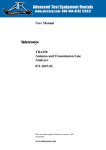
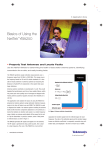
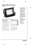
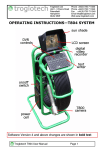
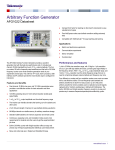
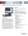
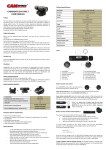
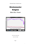
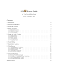
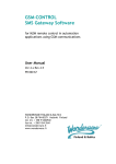
Application Note
Testing Antenna Systems with Tower
Mounted Amplifier
In today's competitive environment, it is very easy for
mobile subscribers to change their provider. This
makes customer satisfaction very important for every
network operator. Network stability needs to be high
and dropped calls need to be minimized. On the
other hand, to reduce investment, it is important to
use a large cell size, where possible, and still have
good coverage. Tower Mounted Amplifiers (TMAs or
receiver preamplifiers) or Mast Head Amplifiers
(MHAs) allow the best sensitivity when larger cells
and weak handset signals are prevalent. To be most
beneficial, TMAs or MHAs need to be mounted as
close to the receive antenna as possible.
This application note describes how to test Antenna
systems with tower mounted amplifiers. You will learn
about typical TMA/HMA configurations and their
effects on reflection measurements. A special focus
will be set on the Insertion Gain and Insertion Loss
while performing gain measurements of tower mounted
amplifier and antenna isolation measurements.
Testing Antenna Systems with Tower Mounted Amplifier
Application Note
Introduction
Antenna systems are commonly tested from the
ground level of base transceiver stations (BTS) by
using an antenna sweeper, such as the YBA250.
With the growing demand for higher data rate
applications, there is a critical need to improve the
uplink (Rx) sensitivity of new networks. Tower mounted
amplifiers (TMA) or masthead amplifiers (MHA) are
installed near the receiver antenna, at the top of the
cell tower, in order to increase the uplink sensitivity
and improve the reception of weak signals. Other
benefits are the extension of coverage area, the
reduction of dropped calls, and an increment of
handset battery life. The relative easy installation of
the TMA makes it even suitable for upgrading existing
base transceiver stations (BTS). Figure 1 shows an
example of an antenna system with TMA.
In an antenna system without TMA, a return loss
(or VSWR) sweep indicates how well the antenna
transmits power by measuring the power that it
reflects compared to the power that it receives. With
the insertion of a TMA, the reflected power might not
come from the antenna itself but from one of the
components of the TMA. Because of this, it is important
to understand the TMA's configuration and basic
operation to properly test antennas with TMA.
The inclusion of a TMA not only introduces new
challenges when testing antenna systems but also
introduces the need to test the TMA itself. The
YBA250 offers Insertion Gain/Loss measurement
that, in conjunction with the YBT250, suits this need.
Insertion Loss measurement can also be used to
perform antenna-to-antenna isolation measurements
which is becoming more important as more antennas
are located on one tower.
2
www.tektronix.com/wireless
Figure 1. Antenna
system with TMA.
In this application note you will first learn about typical
configurations of tower mounted amplifiers, the role of
bias-tees and duplexers, as well as the effects that
amplifiers and filters have on reflection measurements.
We will then describe the procedure to sweep
antennas with TMAs and how to properly use the
distance to fault measurement (DTF) to locate faults.
Then, we will move to specific gain measurements of
tower mounted amplifiers and antenna isolation using
two-port measurements.
Testing Antenna Systems with Tower Mounted Amplifier
Application Note
Common TMA Configurations
A TMA (or HMA) is used to amplify the (weak) uplink
signal. There are several configurations depending on
the BTS requirements; the most common are:
– Received only or simplex configuration (S)
– Single duplex configuration (D)
– Dual Duplex configuration (DD)
These configurations are illustrated in Figure 2.
Received only or simplex configuration (S)
This configuration is used in antenna systems that
have separate Rx and TX antennas, and separate Rx
and TX feed lines to the BTS. The TMA is connected
to the Rx antenna at the antenna port, and to the BTS
at the BTS port.
Single duplex configuration (D)
This configuration is used in antenna systems that
have a common Rx/Tx antenna, and separate Rx and
Tx feed lines to the BTS. A single duplexer isolates
the receiver and transmitter path from the Rx/Tx
antenna. The TMA is connected to the Rx/Tx antenna
at the antenna port, and to the BTS at the BTS port.
Dual duplex configuration (DD)
This configuration is used in antenna systems that
have a common Rx/Tx antenna, as well as, a common
Rx/Tx feed line as shown in Figure 1. The duplexers
isolate the receiver and transmitter paths from the
Rx/Tx antenna and the Rx/Tx feed line, reducing the
amount of antennas and feed lines in the system. The
TMA is connected to the Rx/Tx antenna at the antenna
port, and to the BTS at the BTS port.
All three configurations have a Low Noise Amplifier
(LNA) in the uplink path. A bias-tee injects DC voltage,
from the power distribution unit (PDU), through the
center conductor of the feed line. A second bias-tee,
Figure 2. Typical
internal TMA configurations.
within the TMA, separates the DC voltage, and the RF
signal. The TMA might also have circuitry to bypass
the LNA when no DC power is detected. This is used
in case of TMA malfunctioning or as an emergency
bypass. The provision of the bypass circuitry is
essential when sweeping the Rx band of the antenna
and to measure the (relative) gain on mounted amplifiers.
Configurations of TMAs are sometimes illustrated
using Rx and Tx filters instead of duplexers. The
overall operation is the same. Duplexers and filters
are frequency selected devices. They pass signals
with very little loss inside its frequency bands, while
attenuating all signals outside its bands. A duplexer
isolates the receiver and transmitter signal paths.
www.tektronix.com/wireless
3
Testing Antenna Systems with Tower Mounted Amplifier
Application Note
Figure 3. RF
Signal path with and without bypass.
Figure 4a. No TMA.
Importance of the Bypass Circuitry
When Testing Antenna Systems
Figure 3 illustrates the RF signal path of a dual duplex
TMA with bypass circuitry, and its interaction with the
YBA250 when testing an antenna system.
On the Rx side, the RF signal path between the
YBA250 and the antenna depends on the condition of
the bypass circuitry. When the bypass relay is closed,
the LNA is bypassed and the YBA250 “sees” the
antenna through the filter and the bypass connection.
When the bypass relay is open, the YBA250 does not
“see” the antenna but the output of the LNA. Under
this condition the uplink (Rx) side of the antenna
cannot be tested. Typically, the DC voltage, applied
through the center conductor of the feed line, is used
to control the bypass circuitry.
How Filters and Amplifiers Affect
the Measurement
In order to demonstrate the effect of filters and
amplifiers on the return loss, we are going to measure
a real antenna system. Figure 4a shows a return loss
measurement screen of an antenna system that
includes a 42-foot feed line, a jumper cable and a
Yagi antenna (824 MHz - 896 MHz). It has a reasonable
return loss with values greater than 18 dB.
4
www.tektronix.com/wireless
Figure 4b. Blue: LNA
bypassed, Yellow: No TMA.
You then connect a TMA-DD between the feed line
and the Yagi antenna. The Rx and Tx frequency bands
for this TMA are [835.0 - 849.0] MHz and [880.0 - 896.0]
respectively. It also includes a bypass circuitry.
If you now measure again with no DC power applied
to the TMA, so that the bypass relay is closed, you will
find a result similar to the one shown in Figure 4b. It
shows both traces together and inside the Rx and Tx
frequency bands, you can see that the return loss is
still greater than 18 dB. The performance inside the
Rx and Tx bands was not affected. Outside these
bands, the return loss is much lower. It is caused
by the very low return loss of the duplexer at those
frequencies, which dominates the overall antenna
system performance.
Testing Antenna Systems with Tower Mounted Amplifier
Application Note
Figure 4c. LNA
bypassed. Blue: failure, Yellow: Antenna.
Figure 4d. Blue: LNA
ON, Yellow: LNA bypassed.
Keeping the LNA OFF and the bypass relay closed,
you can then simulate a severe failure by disconnecting
the Yagi antenna and measure again. Figure 4c
illustrates how much lower the return loss within the
Rx and Tx bands is (blue line). On the Rx band, the
resulting return loss is slightly better because it
is also affected by the LNA output and the
bypass characteristics.
You can now reconnect the antenna, turn the LNA
on, and measure once more. Figure 4d shows both
antenna systems: the blue line measures when the
LNA is ON, and the yellow line when the LNA is
bypassed. Even though the performance of the antenna
system in the Rx side changes in shape, it is still
greater than 18 dB. Changes are more noticeable
on the edges outside the Rx band which is due to
the different transient properties of the LNA and
the duplexer.
Keeping the LNA ON, you can simulate a severe
failure by disconnecting the antenna. Figure 4e
shows that the degradation on the Rx side is not
nearly as severe as the degradation in the Tx side.
This confirms that when the LNA is ON, the YBA250
does not “see” the antenna, but rather, sees the
output impedance of the LNA.
Figure 4e. LNA
ON. Blue: failure, Yellow: antenna.
Procedure to Sweep Antennas with
TMA Using the YBA250
When making return loss (VSWR) sweep measurements the key is to bypass the LNA so that the test
equipment can “see” the antenna on the Rx band.
The general procedure on the YBA250 is as follows:
Select Return Loss measurement.
If greater accuracy is desired, perform a
(one-port) User Calibration at the end of the
precision test jumper.
Connect precision test jumper to the RF port of the
bias-tee (blue test point in Figure 1).
Make sure the amplifier is bypassed. If a bypass
circuitry is not available in your TMA, only the
Tx band of the antenna will be swept.
www.tektronix.com/wireless
5
Testing Antenna Systems with Tower Mounted Amplifier
Application Note
Select frequency parameters to cover Rx and Tx
frequency bands.
Connect precision test jumper to the feed line (or
the jumper in your system before the feed line).
Perform measurement. Press Auto Scale (you might
obtained similar results to the blue trace in Figure 4b).
Setup DTF measurements using the Distance
Options setup page (Edit->Distance Option). Select
“Cover Distance” and set the distance to somewhat
longer than the feed line.
When the Return Loss (VSWR) in frequency mode
shows a problem with the system, a Distance To Fault
(DTF) measurement is performed to find where the
fault might be. To improve distance resolution, DTF
requires sweeping with a wide frequency range. The
wider the frequency range the smaller (better) the
distance resolution is.
When no frequency selective components, such as
antennas, bias tees, or TMAs are present, and a
50 Ohm load is on the far end of the antenna feed,
DTF technology can work at its best and most
accurate. When antennas, bias tees and TMAs are
present, two options exist.
– First, the DTF sweep can still be made over a
wide frequency, as in the ideal case mentioned
above. In this case, frequencies outside the pass
band of the components will be swept. The return
loss of the components will be artificially high, but
the distance resolution of the measurement will
be preserved.
– Second, the DTF sweep can be made over a
reduced frequency range. This will allow the
measurement to be made with greater return loss
accuracy, but with less distance resolution.
As an example of frequency selective equipment, the
Bias-tees normally used for TMA installations may be
frequency selective and may contain a 1/4 wave
shorting stub for lightning. The narrower bandwidth
bias-tees may limit the distance resolution of the DTF.
To perform a DTF measurement under ideal conditions
and obtain the most accurate results:
Remove all frequency selective components and
terminate the end of transmission line system (feed
line, jumpers and connectors) with a 50 Ohm load.
This will allow the best and most accurate
measurements to be made.
Select Distance To Fault measurement.
Perform a (one-port) User Calibration at the end of
the precision test jumper.
6
www.tektronix.com/wireless
Perform measurement. Press Auto Scale.
If, under these conditions, the DTF measures a
healthy system (high return loss for connectors,
jumpers, and feed line) any problems may be due
to the TMA.
To perform measurements with frequency selective
components in place, the procedure is similar but
instead of selecting “Cover Distance” in the procedure
above, select “Limit Bandwidth” and set the bandwidth as wide as possible given the components
installed. In the case that a TMA is present, you likely
will need to cover only the uplink or downlink frequency
band. (Also, make sure that the TMA is in bypass
mode.) Limiting the frequency of the sweep will
reduce the distance and return loss accuracy, but can
give a useful indication of the health of your antenna
system, particularly when compared to other, similar,
antenna systems.
Testing Tower Mounted Amplifier
before Installation
In previous sections we described the use and advantages of antennas with Tower Mounted Amplifier. You
learned what to consider when testing such antenna
systems, the effects of filters and amplifiers on your
measurement as well as the procedures to sweep
antennas with TMA. This section now will move
away from the Antenna system and uniquely focus
on testing the TMA itself.
The YBA250 is capable of performing two-port measurements (Insertion Gain and Loss) when used in
conjunction with the NetTek® YBT250. A normalization
kit, such as the YBAC2 (or equivalent) is required to
make more accurate insertion measurements. Other
accessories used for these tests are:
– DC power supply (Tektronix Part Number
119-7017-00 or equivalent).
Testing Antenna Systems with Tower Mounted Amplifier
Application Note
Figure 5a. IG
measurement after User Normalization.
Figure 5b. Normalization
and Measurement Setups.
– Bias-tee (Tektronix Part Number 015-0718-00
or equivalent).
– BNC to DC adapter (Tektronix Part Number
012-1686-00 or equivalent).
Test procedure
Prepare the YBA250/YBT250 to perform two-port
measurements for a TMA.
– Set up the cabling as shown in the Normalization
section of Figure 5b.
Select Insertion Gain/Loss button, and Insertion
Gain measurement type. The default output power
level is -20 dBm.
Check the manufacturer's gain specification to make
sure the power at the RF INPUT (YBT250) will not
exceed its maximum value. If it might exceed the
maximum, you can change (lower) the output
power level.
Select frequency range (appropriate to the TMA).
Perform a User Normalization following the wizard's
instruction. Make sure not to apply DC power to the
bias-tee during normalization.
Measurements immediately after normalization will
display reference trace at 0 dB as shown in Figure 5a.
Disconnect the through connector and connect the
TMA as shown in Figure 5b.
Figure 5c. Insertion
Gain for a TMA-DD.
Figure 5c shows the insertion gain of a TMA-DD for
both, the Rx and Tx frequency bands ([835.0 - 849.0]
MHz and [880.0 - 896.0] respectively). It has a 13 dB
gain over the Rx band, which complies with the
manufacturer's specification.
For all TMA configurations (single, single duplex and
dual duplex) the measurement setup is the same:
connect the BTS port of the TMA to the bias-tee
(YBT250 side), and the ANT port of the TMA to the
attenuator at TEST PORT (YBA250 side). This test
setup might be difficult to realize when the TMA is
already mounted on the tower.
Apply DC power to the DC port of the bias tee.
Perform Insertion Gain measurement and press
Auto Scale.
www.tektronix.com/wireless
7
Testing Antenna Systems with Tower Mounted Amplifier
Application Note
Testing Tower Mounted Amplifier
after Installation
Caution: Please check your country's laws regarding
transmitters before using the NetTek® analyzer to
transmit a test signal.
When the Tower Mounted Amplifier is already mounted
to the tower, you can only measure its relative gain (as
opposed to the absolute gain value as described in
previous section).
The purpose of this test is to verify that the TMA is
working properly. The relative gain is obtained by
comparing the signal change at the BTS when the
amplifier is ON and when it is bypassed. For this test,
you may use the bias-tee and the DC power supply
(from the PDU) already in your system.
The key point for this test setup is to transmit the test
RF signal up to the TMA within the Rx frequency
band. There are several options to accomplish this
and some of them are:
– Use a directional antenna as the Tx antenna at
ground level pointing the Tx/Rx antenna where the
TMA under test is mounted.
Figure 6a. TMA testing when using a directional antenna.
– Use an available Tx antenna mounted in the tower.
Test procedure
Setup YBA250 two-port measurement.
– Select to Insertion Gain measurement type.
Setup frequency parameters according to the
Rx frequency range of the TMA.
– Verify the output power level is in compliance
with transmission regulations. Adjust the level
if necessary.
8
www.tektronix.com/wireless
Using a YBAC2 or equivalent normalization kit,
perform a User Normalization following the wizard's
setup and instructions.
If using a directional antenna, you may use a setup
as illustrated in Figure 6a. Connect the 10 dB
attenuator at TEST PORT (YBT250) to the directional
(Tx) antenna. Secure the antenna to make the signal
path as constant as possible during the test.
Testing Antenna Systems with Tower Mounted Amplifier
Application Note
If using a transmit antenna on the tower, set up as
illustrated in Figure 7. When using a Tx antenna that
is mounted at the tower you might need to increase
the output power level to counteract the isolation
between antennas. Make the antenna a YAGI,
pointing at the tower.
Connect the 10 dB attenuator at RF INPUT (YBT250)
to the coax from antenna.
Bypass the LNA, by removing DC power, and make
the insertion gain measurement. Save trace
(File->Save->“Filename”).
Turn ON LNA, by connecting DC power, and make
insertion gain measurement. You may make several
sweeps to ensure that the TMA is being powered on.
Using the dual trace capability of the NetTek®
analyzer, display both traces on the same screen
(Edit->Insertion Tab->Gain->View Trace 2-> “Filename”).
You can view marker M1 on trace 1 (View->Marker
1->Trace1) and market M2 on trace 2. (View->
Marker 2->Trace 2). Then you can use the M1-M2
indicator to obtain the relative gain.
For more details on how to work with traces, refer to
the YBA250 User Manual.
Figure 6b shows the relative gain result for a similar
setup as of Figure 6a. Each trace represents the total
gain (or loss) which includes loss of cables and path.
Figure 6b. Relative gain measurement result.
The yellow trace is the total gain (loss) when the LNA
is bypassed, and the blue trace is the total gain (loss)
when the LNA is ON.
Since both measurements are performed using the
same signal path, except at the LNA, the difference
between trace 1 and trace 2 (at Rx frequencies) gives
approximately the gain of the LNA minus the loss of
bypass circuitry. This result is approximately 14.5 dB
in our setup.
It's interesting to know that the measurement when the
LNA is bypassed actually is the antenna isolation
measurement. There are more details on this in the
next section.
www.tektronix.com/wireless
9
Testing Antenna Systems with Tower Mounted Amplifier
Application Note
Measuring Antenna-to-Antenna
Isolation
Caution: Please check your country's laws regarding
transmitters before using the NetTek® analyzer to
transmit a test signal.
Antenna-to-antenna isolation becomes more
important as more antennas are located on a common
tower. The easiest method of improving isolation, by
increasing the distance from each other, is limited.
Even though antennas in different sectors are pointing
to different directions, signals that are transmitted
from one sector can also be received at another
sector. This is also known as co-channel or co-band
interference. The lower the isolation between antennas,
the greater the potential of interference signals at
the receiver.
The basic setup to measure antenna isolation is
similar to the one illustrated in Figure 8.
Test procedure
Setup YBA250 two-port measurement.
– Select to Insertion Loss measurement type and
setup frequency parameters to cover Rx and
Tx frequencies.
Perform a two-port normalization following the
wizard instructions.
10 www.tektronix.com/wireless
Figure 7. Installed TMA testing when using a transmit antenna.
Testing Antenna Systems with Tower Mounted Amplifier
Application Note
Connect the 10 dB attenuator at TEST PORT
(YBT250) to the Tx antenna's coax.
Connect the 10 dB attenuator at RF INPUT (YBT250)
to the Rx antenna's coax.
Make insertion loss measurement. Press Auto Scale.
The insertion loss measured at the Rx band is the
amount, in dB, that a signal sent by the transmitter (at
Tx antenna side) is reduced by before interfering in
the receiver (at Rx antenna side).
Conclusion
Tower Mounted Amplifiers (TMA) and Masthead
Amplifiers (MHA) are playing a key role In order to
maximize the sensitivity of the receiver link. This
enables antennas to receive even weak signals,
extends the coverage area, and helps to reduce the
number of dropped calls. To ensure the proper functionality there is the clear need to test such systems
as well as the TMAs themselves. The Tektronix
YBA250 and YBT250 with is Insertion Gain/Insertion
Loss measurement capabilities are perfectly equipped
to meet these needs.
To find out more about other measurement
functionalities, application notes or technical briefs,
please visit www.tektronix.com/wireless.
Figure 8. Antenna isolation measurement.
www.tektronix.com/wireless
11
Contact Tektronix:
ASEAN / Australasia / Pakistan (65) 6356 3900
Austria +41 52 675 3777
Balkan, Israel, South Africa and other ISE Countries +41 52 675 3777
Belgium 07 81 60166
Brazil & South America 55 (11) 3741-8360
Canada 1 (800) 661-5625
Central Europe & Greece +41 52 675 3777
Central East Europe, Ukraine and Baltics +41 52 675 3777
Denmark 80 88 1401
Finland +41 52 675 3777
France & North Africa +33 (0) 1 69 81 81
Germany +49 (221) 94 77 400
Hong Kong (852) 2585-6688
India (91) 80-22275577
Italy +39 (02) 25086 1
Japan 81 (3) 6714-3010
Luxembourg +44 (0) 1344 392400
Mexico, Central America & Caribbean 52 (55) 56666-333
Middle East, Asia and North Africa +41 52 675 3777
The Netherlands 090 02 021797
Norway 800 16098
People’s Republic of China 86 (10) 6235 1230
Poland +41 52 675 3777
Portugal 80 08 12370
Republic of Korea 82 (2) 528-5299
Russia, CIS & The Baltics 7 095 775 1064
South Africa +27 11 254 8360
Spain (+34) 901 988 054
Sweden 020 08 80371
Switzerland +41 52 675 3777
Taiwan 886 (2) 2722-9622
United Kingdom & Eire +44 (0) 1344 392400
USA 1 (800) 426-2200
USA (Export Sales) 1 (503) 627-1916
For other areas contact Tektronix, Inc. at: 1 (503) 627-7111
Updated November 3, 2004
For Further Information
Tektronix maintains a comprehensive, constantly expanding collection
of application notes, technical briefs and other resources to help engineers
working on the cutting edge of technology. Please visit www.tektronix.com
Copyright © 2005, Tektronix, Inc. All rights reserved. Tektronix products are covered by U.S. and foreign
patents, issued and pending. Information in this publication supersedes that in all previously
published material. Specification and price change privileges reserved. TEKTRONIX and TEK are
registered trademarks of Tektronix, Inc. All other trade names referenced are the service marks,
trademarks or registered trademarks of their respective companies.
1/05 FLG/WOW
2EW-18514-0