1
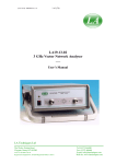
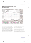
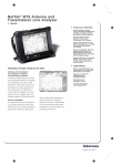
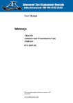
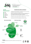
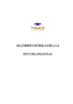
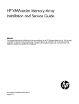
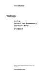
Application Note
Basics of Using the
NetTek YBA250
®
Properly Test Antennae and Locate Faults
Use the NetTek YBA250 for determining the health of base station antenna systems, identifying
transmission line trouble, and easily locating faults.
The YBA250 performs swept reflection measurements over a
frequency range from 25 MHz to 2500 MHz. This range covers
the frequency bands for 2G and 3G cellular standards. It is also
able to locate problems in antenna systems by measuring the
Distance to Fault (DTF) of components in the system that cause
large reflections.
Antenna systems constitute an essential part of a cell. They could
degrade their performance over time or have sudden failures, which
may cause poor voice quality, loss of coverage and dropped calls.
Testing antenna systems regularly increases the reliability of a
cell site.
This application note explains the basics of using the YBA250 to
properly test antenna systems using calibrated reflection measurements in the form of Return Loss and VSWR. The YBA250 is used
to diagnose the health of an antenna system including the antenna
itself and the feed line components attached to it. An antenna is a
device that radiates or absorbs radio waves in a certain frequency
range. Ideally, an antenna would radiate all the power that is sent
to it by the transmitter. In practice, however, some of that power
is reflected back, as seen in Figure 1.
The YBA250 generates RF signals and applies it to the antenna.
The RF signal is generated in steps, point by point, from a start
to a stop frequency. The core of the YBA250 is a test set that
1
www.tektronix.com/wireless
Magnitude of the Reflection Coefficient
ρ=
Vreflected
Vincident
Return Loss
RL = –20log10 (ρ) = –20log10
( )
Vreflected
Vincident
Voltage Standing Wave Ratio
VSWR =
1+ρ
1–ρ
Incident signal
Reflected signal
Figure 1. Antenna reflection characteristics.
separates the incident signal from the reflected signal for each
frequency. The ratio of the reflected signal and the incident signal,
known as reflection coefficient, is computed, corrected using calibration data, and displayed in the form of return loss or VSWR.
Basics of Using the YBA250
Application Note
Figure 2 shows an example of a return loss measurement of a GSM
antenna that was connected directly to the test port of the YBA250.
The frequency band of this antenna is from 1850 MHz to 1990
MHz. The Blue line in Figure 2 shows the measured return loss of
the antenna. The Green line is a user-defined mask entered into the
YBA250 that shows the manufacturer’s specifications. When the
antenna meets the specification, the line is Green. The line turns
Red when it does not.
Return loss indicates how far down from the incident signal (at 0 dB),
the reflected signal is. A larger value of return loss (farther down)
indicates a smaller reflected signal, meaning a better antenna. In
other words, more power is radiated and less power is reflected.
All reflection measurement test sets introduce errors to the actual
measurement results. They are removed by a process called calibration. In general, reflection measurements are usually made as a
comparison of the device being measured to a known standard.
This standard is assumed to be perfect. The process of comparing
is called “calibrating” the measurement equipment.
Calibration
Calibration is a process that compensates for errors introduced by
the reflection measurement test set. This process uses high-precision
measurement standards whose characteristics are precisely known.
The YBA250 calculates the difference between the measurement
results from the calibration standards and the ideal results to create
correction data. This data is used to remove deterministic errors
from the measurement results.
The YBA250 uses a calibration kit that contains three precision
standards: an Open, a Short and a Load, such as the YBA250C1
(or equivalent). The accuracy of the measurements is determined
by the quality of the standards, primarily Load. A measurement may
indicate a return loss of 50 dB. This reading is meaningless, however,
if the standard load used to make the calibration was specified to
be only 40 dB.
The calibration process in the YBA250 provides a unique feature.
It is performed across its entire frequency range. Therefore, changing
the frequency parameters of a measurement does not require
re-calibration.
The YBA250 offers two types of calibration: Factory Calibration and
User Calibration. The Factory Calibration (Factory Cal) is done during
manufacturing and the results are stored in non-volatile memory
so that it can be used at any time. A User Calibration (User Cal) is
2
www.tektronix.com/wireless
Figure 2. Return Loss of a GSM antenna (Blue line).
performed before taking measurements and it also compensates
for changes in temperature and component aging to ensure the
most accurate measurement. A User Cal can be stored in the
YBA250 and it can be recalled at another time. When using a
non-precision cable to connect the YBA250 to the device under
test, we recommend performing the calibration at the end of the cable
to remove the effect of the jumper cable over the measurement results.
The Factory Cal Can be Used When:
The user does not need the best accuracy for his/her measurements
A User Cal Should be Used When:
The user wants to obtain the most accurate measurement possible
The calibration is done at the end of a jumper cable (a cable between
the YBA250 test port and the device under test)
To Perform a Quality Calibration, We Recommend:
Use of a high-precision calibration kit, such as the YBA250C1
Properly-tightened standard to ensure a good connection. A loose
connection will produce poor calibration data
Minimal cable movement when calibrating at the end of the cable
More detailed information on calibration and accurate measurements
can be found at [1] and [2] (see page 7).
Basics of Using the YBA250
Application Note
Performing a New Use Calibration
Set output power
(if necessary)
Select where to perform
calibration
(Test port, end of cable)
Antenna Testing Performed
in the Field
Antenna tests are usually performed at ground level, as shown in
Figure 4. The measured return loss of the antenna will be affected
by the connector(s), jumper cable(s) and transmission line (feed-line
or feeder) that are in the path between the YBA250 calibrated
output and the antenna port.
Antenna
Calibrate using OPEN, SHORT,
and LOAD in any order
Jumper cable
OK
Cancel
Automatically saved as
the current cal data set
Transmission line
(feeder)
OK
Save
Possible test points
Select
name
(to test points)
Test Port
YBA250
Connectors
Duplexer
BTS House
Jumper cable
Note: This graphic shows only one sector for simplicity.
Figure 4. Antenna testing in the field.
Figure 3. User calibration flowchart.
Figure 3 shows a flowchart for the calibration process. A more
detailed flowchart can be found in the YBA250 User Manual [3]
(see page 7).
The YBA250 makes measurements in two domains: frequency
domain and distance domain. Tests using return loss (or VSWR)
versus frequency are performed to determine the health of the
antenna system. In the event that the antenna system fails these
tests, distance domain diagnosis, known as Distance to Fault (DTF),
is then performed in order to locate the fault. The conversion from
frequency to distance is achieved by processing the reflection
coefficient data using digital signal processing algorithms.
www.tektronix.com/wireless
3
Basics of Using the YBA250
Application Note
Using a Jumper Cable
Another practical issue for antenna testing in the field is that the
test points are usually in places that may make it difficult to directly
connect the YBA250 test port to them (see Figure 4). Thus, a jumper
cable is normally used between the test port of the YBA250 and the
test points. The jumper cable’s reflection characteristics and loss
cause errors in the reflection measurement. Both of these errors
can be eliminated by calibrating the instrument at the end of the
jumper cable.
If a standard calibration kit is not available, the YBA250 can still
make calibrated measurements using its Factory Calibration (Factory
Cal). Since this calibration is performed at the test port, measurement
test setups requiring the use of a jumper cable will be affected by the
characteristics of the jumper cable. When performing measurements
using the Factory Cal, it is recommended to use a precision jumper
cable, such as the Tektronix part number 012-1619-00. The errors
introduced by this cable are mainly due to its loss and not its reflection
characteristics. These errors can be removed from the return loss
results by subtracting two times the value of the cable loss from the
return loss results (equivalent to raising the return loss waveform
by twice the value of its cable loss).
Figure 5 shows the return loss results of a GSM antenna system
when using a precision cable of 1.4 dB loss. The Blue line is the
measured return loss using Factory Cal. The Yellow line is the measured return loss using User Cal at the end of the precision jumper
cable. Notice that the effects of the precision jumper cable are primarily to increase the actual return loss by about 2.8 dB. In other
words, it makes the overall return loss measurement looks better
(farther down) by about 2.8 dB.
To obtain more accurate results, we recommend calibrating
the YBA250 at the end of the jumper cable.
4
www.tektronix.com/wireless
Figure 5. Return Loss of a GSM antenna (Blue: Factory Cal;
Yellow: User Cal at end of cable).
Other Devices in the Signal Path
In some systems, a duplexer or filter may be found in the signal
path between the test port of the YBA250 and the antenna’s port.
A duplexer is a device that isolates the receiver and the transmitter
paths allowing the use of a common antenna, reducing the numbers
of antennae and feed lines in the system. A filter is a device used to
pass frequencies within its frequency band with very little loss while
attenuating all signals outside its band. Both components pass signals
over a limited range of frequency and reflect those outside that range.
Measuring return loss or VSWR with them in the signal path will
indicate the quality of the entire system attached to the base station.
Filters and duplexers present in the signal path will, to some degree,
mask the antenna’s performance.
For more accurate results about the antenna system, only
those components pertinent to the antenna system should be
in the signal path.
Basics of Using the YBA250
Application Note
Making Measurements in the
Frequency Domain
Making Measurements in the Distance
Domain (DTF)
Return Loss or VSWR in the frequency domain is the primary
measurement tool to diagnose the health of an antenna system.
The distance domain is return loss, or VSWR, measured as a function
of distance along the coaxial cable connected to the YBA250. This
secondary measurement tool is best known as Distance to Fault
(DTF). It is used to locate faults when the measurements in the
frequency domain indicate a problem; in other words, when the frequency-domain return loss results are out of spec. When performing
DTF measurements, the YBA250 still sweeps the system under test
in frequency, and the calibrated reflection coefficients are computed.
Then, these results are transformed to the distance domain using
digital signal processing algorithms.
Calibration Set. Choose the most appropriate calibration data set
(see Calibration)
Frequency Setup. There are two ways to select how wide to sweep.
Select the uplink/downlink button of the cellular standard used or dial
the Start and Stop frequencies
Saving Results. We recommend saving the results to monitor a possible
degradation in the antenna system over time
Figure 6 shows a flow diagram of the main steps when doing a
frequency domain measurement. The YBA250 User Manual [3]
(see page 7) has a detailed description of this process.
Set output power
(if necessary)
The distance information is contained in how much the phase of the
reflected signal changes with variations in frequency. The length of
the coaxial cable(s) and the group delays of the devices in the signal path affect the change in phase. Each distance point in the DTF
measurement is affected by all frequencies in the sweep. Therefore,
one must be careful when setting the DTF in order to obtain
meaningful results.
The basic relationships between frequency and distance are
given by:
Set Calibration
(Use Cal or Fact Cal)
Dmax =
Vp * C
1
BW
∆f =
Set start and stop
frequencies
[a]
*
2
=
∆f
Fstop – Fstart
∆d =
Dmax
=
N–1
Options
Run
Measurement
[b]
N–1
N–1
Vp * C
2
1
*
[c]
BW
Set mask
Save results
Others
Figure 6. Making frequency domain measurements.
where,
Dmax
is the maximum measurable distance
Vp
is the velocity of propagation of the coax cable
with respect to the speed of light
C
is the speed of light
N
is the number of frequency points in the sweep
BW
is the frequency bandwidth
∆f
is the frequency step of the sweep
∆d
is the distance resolution
www.tektronix.com/wireless
5
Basics of Using the YBA250
Application Note
Notice that D max is mainly determined by the ∆ f as indicated by
Equation [a]. When a measurement with wide frequency span
is possible, more frequency points can be acquired. This gives
a better resolution in distance as indicated by Equation [c].
The YBA250 can acquire up to 4096 frequency points. This
capability is used to offer several levels of distance resolution
and maximum distance according to the method used to setup
the DTF as explained below.
Calibration Set. Choose the most appropriate calibration data set
(see Calibration)
Distance Setup. The YBA250 offers a unique configurable tool that makes
it easier for the user to set up the DTF. On previous products, the DTF
mode has been difficult to adjust to trade off the start and stop frequency
and the number of measurement points to get the total range and distance
resolution desired. The YBA250 is designed to allow the user to set the
controls in terms of performance required. The user can select between
two setup modes: by Cover Distance and by Limit Bandwidth
Cover Distance is recommended when no frequency-limited
devices, such as filters or duplexers, are in the signal path. In this
mode, the user enters the desired total distance and the YBA250
automatically adjusts values to make sure that the actual measured
distance covers the user’s desired distance. Thus, the actual covered
distance may be greater than or equal to the user’s desired distance,
but will not be less. In this mode, a change in the distance resolution relates to a change in the number of frequency points. The
methods for this mode are Fast, Normal or High Resolution. Fast is
used if a high update rate is desired but high resolution is not
required. Normal gives a somewhat slower update rate but better
distance resolution. The High-Resolution method gives the highest
distance resolution, making it possible to identify which end of a
jumper, at the top of a tower, needs repair. This method requires
longer measurement time.
6
www.tektronix.com/wireless
Limit Bandwidth is recommended when frequency-limited devices,
such as filters or duplexers, are in the signal path and one would
like to “see” beyond these devices. The user enters the frequency
parameters by choosing the central frequency and bandwidth. The
YBA250 then finds the distance-related parameters. The actual
bandwidth used in the measurement will be less than or equal to
the value entered by the user. This guarantees that the signal stays
within the specified range. Notice that according to Equation [c],
fixing the frequency bandwidth also fixes the distance resolution.
When the bandwidth is fixed, a change in the number frequency
points changes the maximum distance as indicated by Equation [b].
In this case, the methods are Fast, Normal and Long Distance. If a
fault is located beyond these devices, the distance to the fault may
be displayed as being farther away than it actually is. This occurs
because these devices add delay to the RF signal traveling, forwards
and backwards, through them.
If the DTF setup contains frequencies outside the specifications of a
frequency-limited device, the DTF results might be meaningful only
at distances less than or equal to the distance where the device is
and will never be good beyond it. In general, the results may be poor
or completely useless. This occurs because the device will reflect
the RF signal at frequencies outside its bandpass and the effects
of measurement at each point in the sweep are combined at each
distance point of the DTF measurement. In other words, reflections off
the device’s input at some frequencies will affect the compound result
at each distance point in the distance domain. A fault that does not
exist may be shown at the device’s input and a fault beyond the
device may not be “seen” by the instrument.
DTF could be used to determine the return loss of an antenna by
taking the amplitude of the DTF at the distance where the antenna
is. This method, however, is not nearly as accurate as the return loss
vs. frequency measurement described in Making Measurements in
the Frequency Domain. If used, however, one should set up the DTF by
Limit Bandwidth and be careful to make sure that the sweep is not
wider than the antenna’s bandwidth. The return loss, or VSWR, shown
at the distance where the antenna is will be roughly correct but will
be affected by the transmission line loss vs. frequency selected in
the DTF setup.
Basics of Using the YBA250
Application Note
The principal goal of the DTF measurement is to locate the fault;
therefore, a smaller distance resolution is desired which requires
measurements over a wide frequency range. Limiting the frequency
range to the bandpass of the in line device will result in poor
distance resolution.
Figure 7 shows a flow diagram of the main steps when doing
a DTF measurement. The YBA250 User Manual [3] contains a
detailed description of this process.
Set output power
(if necessary)
Set Calibration
(Use Cal or Fact Cal)
Is there any
frequency-limited
device in the signal
path? (filter,
duplexer)
Yes
Want to see beyond
those devices?
Yes
Conclusion
The YBA250 performs swept reflection measurements, in the form
of return loss and VSWR, in frequency domain and distance domain.
Return loss (VSWR) in the frequency domain is the primary tool to
diagnose the health of an antenna system. If the diagnostics suggest
there is a fault, DTF measurements are taken to determine where
the fault is.
Reflection measurements are usually calibrated to improve accuracy.
The quality of the standards used during the calibration determines
the accuracy of the measurements. Since the calibration process in
the YBA250 is performed across its entire frequency range, changing
the frequency parameters of a measurement does not require
re-calibration. Other unique features of the YBA250 are the factory
calibration set and the DTF setup. The former allows making calibrated measurement when the standards are not available. The latter
allows the user to set up the DTF by distance or frequency and view
their actual values before performing measurements. These unique
features translate into time savings when testing antenna systems.
Recommended Literature
No
Set DTF by
Cover Distance
Set DTF by
Limit Bandwidth
Options
Run
Measurement
Save results
Others
Figure 7. Making DTF measurements.
[1] Application Note: Accurate Antenna Measurements and the
NetTek YBA250
Literature Number: 2GW-15651-0
URL: http://www.tek.com/Measurement/App_Notes/2G_15651/
eng/2GW_15651_0.pdf
[2] Application Note: Accurate Reflection Measurements and the
NetTek YBA250
Literature Number: 2GW-15653-0
URL: http://www.tek.com/Measurement/App_Notes/15653/
eng/2GW_15653_0.pdf
[3] YBA250 User Manual
Part Number: 071-1047-01
www.tektronix.com/wireless
7
Contact Tektronix:
ASEAN / Australasia / Pakistan (65) 6356 3900
Austria +43 2236 8092 262
Belgium +32 (2) 715 89 70
Brazil & South America 55 (11) 3741-8360
Canada 1 (800) 661-5625
Central Europe & Greece +43 2236 8092 301
Denmark +45 44 850 700
Finland +358 (9) 4783 400
France & North Africa +33 (0) 1 69 86 80 34
Germany +49 (221) 94 77 400
Hong Kong (852) 2585-6688
India (91) 80-2275577
Italy +39 (02) 25086 1
Japan 81 (3) 3448-3010
Mexico, Central America & Caribbean 52 (55) 56666-333
The Netherlands +31 (0) 23 569 5555
Norway +47 22 07 07 00
People’s Republic of China 86 (10) 6235 1230
Poland +48 (0) 22 521 53 40
Republic of Korea 82 (2) 528-5299
Russia, CIS & The Baltics +358 (9) 4783 400
South Africa +27 11 254 8360
Spain +34 (91) 372 6055
Sweden +46 8 477 6503/4
Taiwan 886 (2) 2722-9622
United Kingdom & Eire +44 (0) 1344 392400
USA 1 (800) 426-2200
USA (Export Sales) 1 (503) 627-1916
For other areas contact Tektronix, Inc. at: 1 (503) 627-7111
Updated 20 September 2002
For Further Information
Tektronix maintains a comprehensive, constantly expanding collection of application notes, technical briefs and other resources to help
engineers working on the cutting edge of technology. Please visit
www.tektronix.com
Copyright © 2003, Tektronix, Inc. All rights reserved. Tektronix products are covered by U.S. and
foreign patents, issued and pending. Information in this publication supersedes that in all previously
published material. Specification and price change privileges reserved. TEKTRONIX and TEK
are registered trademarks of Tektronix, Inc. All other trade names referenced are the service marks,
trademarks or registered trademarks of their respective companies.
05/03 HB/SFI
2EW-16667-0
8
www.tektronix.com/wireless