1
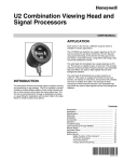
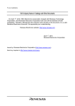
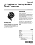
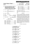
Honeywell Model 700/800 Signal
Processor and Viewing Head
USER MANUAL
• Model 700ACSP Universal 85-265 VAC powered, plus
24VDC backup.
• Model 700DCSP 22-26VDC powered, plus 24VDC
backup.
The two Model 700 signal processors are similar, with 12
push-buttons, a two-digit numeric display, and four LED status
indicators for operator interface. The only difference between
the two is that one accepts AC power and the other accepts
DC power. Both models also accept 24VDC backup power.
Most of the signal processor connections are made through
Phoenix plug-in connectors. Communication connections are
made through modular phone jacks located at the top of the
signal processors (Fig. 8).
Both signal processor models mount on a standard 35 mm
DIN rail. They snap into place and may be released from the
rail using a flat screwdriver.
There are two types of viewing heads—IR/flicker-sensitive and
UV-sensitive—with various features offered resulting in ten
different models. See Table 1 on page 2 for details.
The S702 and S706 viewing head housings are larger in
diameter than the S80X series, are made of aluminum, and
are secured with over-center latches to their mounting blocks
(Fig. 9). In contrast, the S802 and S806 viewing head
housings are smaller in diameter and are made of stainless
steel (Fig. 10). An 800 series viewing head is secured in its
mounting block by a friction twist-lock.
APPLICATION
The Honeywell Model 700ACSP and Model 700DCSP signal
processors are single-channel, fail safe, flame monitoring
systems when used In conjunction with the S70X/S80X
viewing heads. They offer easy setup, excellent discrimination,
and high reliability.
FEATURES
Viewing heads are interchangeable between the two signal
processor models. Any viewing head in the two families will
work with any of the signal processors.
Two signal processor models are available:
The IR/flicker sensitive viewing heads have a high-pass filter
that passes flicker frequencies above 33 Hz. Some models
have a built-in high pass filter that only passes frequencies
above 155 Hz. The high frequency filter models are identified
by adding “HF” to the model number. The UV models respond
to the level of UV radiation—not UV flicker—so there is no
filter option.
Contents
Application ....................................................................... 1
Features ........................................................................... 1
Specifications ................................................................... 2
Approvals ......................................................................... 3
Installation ........................................................................ 3
Operation ......................................................................... 10
Modbus Communication .................................................. 14
Troubleshooting ................................................................ 17
Maintenance .................................................................... 17
Safety Manual: 700 Signal Processor .............................. 33
Safety Manual: S70X & 80X Viewing Head ..................... 36
Put Bar Code Here
66-2069-02
HONEYWELL MODEL 700/800 SIGNAL PROCESSOR AND VIEWING HEAD
Table 1. Available viewing head models and associated features.
Model
Pipe Fit Connection
0.5 in. NPTM with 50-ft
(15.2 m) pigtail
Connector
S702
X
S702HF
X
S702PF
S802HF
X
S806
X
3.
X
X
X
X
X
X
X
X
X
X
X
X
X
X
UV Detector Spec
S706 & S706PF, S806: UVtron with spectral response 185nm
to 260nm and a peak response at 210nm
All models include Electronic self-check.
Flicker Frequency filter settings available for IR sensor
models.
Gain Selection available through Signal Processor.
UV Optical
Angle of View: 5 degrees (1 inch per foot)
The viewing heads, the viewing head connector, and the cable
provided are watertight, and have NEMA 4X ratings when the
connector is properly tightened with pliers and the cable is
protected from UV exposure.
Cable & Connectors - S70X/S80X Viewing Heads
New installations - highest level of EMI shielding available:
ASY785 --> 50 foot C330S cable with pre-wired ASY786
connector.
ASY785-200 --> 200 foot C330S cable with pre-wired
ASY786 connector.
ASY786 --> Field wireable connector with shield.
The availability of both UV-sensing and IR/flicker-sensing
viewing heads ensures that the flame monitoring systems can
provide good discrimination in most single and some multiple
burners firing a single fuel. UV sensing is appropriate for
monitoring natural gas, some mixed gases and light oil flames.
IR/ flicker sensing is appropriate for monitoring heavy oil and
coal flames.
Dimensions
Refer to Fig. 9 and Fig. 10.
Model 700ACSP & Model 700DCSP Signal
Processer
SPECIFICATIONS
Electrical: Model 700ACSP
Primary Input Power: 85-265VAC, 50-60 HZ, 0.07A Max.
fused (with either V.H. connected)
Battery Backup Voltage: 22VDC to 26VDC, 0.2A DC Max.
fused (with either V.H. connected)
Series 700 and 800 Viewing Heads
MODELS S702, S702PF, S702HF, S702HFPF, S706,
S706PF, AND MODELS S802, S802HF, AND S806
Electrical: Model 700DCSP
Primary Input Power: 22VDC to 26VDC, 250 mA Max. fused
(with either V.H. connected)
Battery Backup Voltage: 22VDC to 26VDC, 0.5A DC Max.,
fused (with either V.H. connected)
Electrical
24VDC Power is supplied by Signal Processor
Environmental
Viewing Head Sealing: NEMA TYPE 4X rated when the
molded connector ring is tightened with pliers and a UV
protection is provided for the cable by installing in conduit.
Ambient Temperature: -40°F to 185°F (-40°C to 85°C)
Outputs
Flame Relay: 2 form C contacts
Self-Checking Relay: 1 form C contact
Relay Contact Ratings: 5A at 125 VAC, 277 VAC, & 30 VDC;
1/8 HP 125 & 250 VAC
Analog Flame Signal: Isolated 0 to 20 mA or 4 to 20 mA
output for remote meters or DCS, 360 ohms maximum
resistance
IR Detector Spec
S702, S702PF, S702HF, S702HFPF, S802, S802HF:
Germanium photodiode with spectral response 950nm to
1710nm (1/2 intensity points) and peak spectral response
at 1400nm
High Pass Filter Pickup: 33 Hz standard, 155 Hz high
frequency option (-HF)
Environmental
Ambient Temperature: 32°F to 140°F (0°C to 60°C)
IR Optical
Angle of View: 1 degree (1.45 in. dia. at 6 ft. or 3.7 cm dia. at
1.8 m)
66-2069—02
X
X
X
X
X
Aluminum Stainless Steel
Housing
Housing
X
X
X
S802
1.
2.
X
X
S706PF
IR Sensor
High
Frequency
Filter 155Hz
X
X
S702HFPF
S706
UVTron
Sensor
Dimensions
Refer to Fig. 11 and Fig. 12.
2
HONEYWELL MODEL 700/800 SIGNAL PROCESSOR AND VIEWING HEAD
APPROVALS
4.
S70X/S80X Viewing Heads (Connector series and Pipe fit
series [PF])
CSA for CLASS I, DIV 2, GROUPS A, B, C, D & T4A
FM 7610/NEMA 4X and CLASS 1, DIV 2, GROUPS A, B, C, D
& T4A*
SIL 3 “Fit for Use”
IECEx CSA 10.0003 Ex nA IIC T4 Gc
-40<Ta<85ºC, -40<TA<185ºF
5.
*IP67/NEMA 4/4X rating applies when connector ring is
properly tightened and cable is UV shielded
700ACSP and 700DCSP Signal Processors
CSA (C, US)
FM
Signal Processor Power
Connections
INSTALLATION
The Model 700ACSP power and relay connections are shown
in Fig. 1. The AC power supply to the 700ACSP Signal
Processor passes through a 2A fuse and an inrush current
limiter.
When Installing These Products...
1.
2.
3.
4.
Read these instructions carefully. Failure to follow them
could damage the products or cause a hazardous
condition.
Check the ratings given in the instructions and one the
products to make sure the products are suitable for your
application.
Installer must be a trained, experienced, flame
safeguard control technician.
After installation is complete, check out product
operation as provided in these instructions.
The Model 700DCSP power and relay connections are shown
in Fig. 2. The maximum current requirement for each
700DCSP is 250mA.
In the Model 700 signal processors the flame relay (RF A/B
ON, OFF, COM) has two sets of FORM C (SPDT) contacts
and the self-check relay (SC ON, OFF, COM) has one set (Fig.
1 and Fig. 2). The self-check relay is energized whenever the
signal processor is powered and is operating normally,
whether the flame relay is energized or not. Internally, the
flame relay is wired in series with the self-check relay (not
shown), which prevents the flame relay from energizing if the
self-check relay is not energized.
Signal Processor Mounting
The 700ACSP and 700DCSP signal processors mount on a
standard 35mm DIN rail. They snap into place and may be
released from the rail using a flat screwdriver.
Unique fail-safe circuitry for the self-check and flame relays
ensure that in the event of any critical component failure
occurrence, system response will be to de-energize the selfcheck relay, which in turn de-energizes the flame relay.
Grounding and Shielding
NOTE: Installer must be a trained, experienced flame
safeguard service technician and should be
familiar with the equipment operation and
limitations and be aware of any applicable local
codes and regulations.
1.
Some of the internal power wiring of the Model 700ACSP and
Model 700DCSP signal processors is shown in Fig. 1 and
Fig. 2. Rectifier diodes separate the battery backup input from
the main power bus until the battery voltage exceeds the
internal DC voltage plus a diode voltage drop. Resettable
fuses (shown as resistors with slashes) and conventional
fuses prevent internal failures from loading the power sources.
With the Model 700DCSP, if a backup battery is to be used
with a main power supply, the two power sources would be
wired as shown in Fig. 2. If no backup battery is to be
installed, the main power supply can be connected at +26V
PWR and GND as shown in Fig. 2 or it can be connected to
the +24V BATT input and GND. It is preferable to use the
battery connections because it takes advantage of the
resettable fuse at the battery input; resettable fuses recover
automatically from a fault within a few seconds after power is
removed. At the +26V PWR input and its associated GND,
conventional1A fuses are used because they are able to
protect against 240VAC being applied by accident (this could
happen if a Model 700DCSP is installed in a cabinet wired for
a Model 700ACSP).
Connect a safety ground to the viewing head housing (if
applicable). A ground screw is provided on the exterior
of the viewing head housing for this purpose.
WARNING
The viewing head housing is grounded through
cable/signal processor, so you must ensure that
AC/DC potentials at ground of signal processor
and viewing head are the same, or damage to the
cable or signal processor can result.
2.
3.
Ensure all igniter wires and cables show no signs of
wear. Replace any igniter cables or wires that are frayed
or cracked.
The viewing head must be electrically isolated from the
burner front.
a. Electrical isolation can be accomplished by
installing an Ultem nipple (R-518-13) or an Ultem
locking coupler adapter (R-518-PT13 or R-518PT13L) in conjunction with a locking coupler (R-518CL13-HTG) between the viewing head flange and
the burner mount.
b. The purge air line should also be isolated from the
viewing head. This can be accomplished by
installing any insulating material, for example a
rubber hose, in between the purge air line and the
viewing head.
The viewing head and all associated cable/conduit must
be at least 12 inches (31 cm) from any source of high
energy or voltage (for example, igniter equipment).
Install a ground wire from the ignition transformer case
to the igniter assembly.
3
66-2069—02
HONEYWELL MODEL 700/800 SIGNAL PROCESSOR AND VIEWING HEAD
+26VDC
+
AC POWER
SUPPLY
GND
APPROVED
0-20 OR 4-20 MA
+
INSTRUMENTATION
360 OHMS MAX
-
.125 A
-t°
2A .4A
CHASSIS,
EARTH, OR
SYSTEM GND
FOR INDICATOR OR
TO VIEWING
HEAD
+
GROUND
M34280
Fig. 1. Model 700ACSP Signal Processor Wiring.
66-2069—02
-
24 V
BACKUP BATTERY
(OPTIONAL)
AC IN
4
HONEYWELL MODEL 700/800 SIGNAL PROCESSOR AND VIEWING HEAD
+26VDC
+
GND
.125 A
LIM
APPROVED
1A
1A
.4A
+26
PWR
0-20 OR 4-20 MA
+
FOR INDICATOR OR
INSTRUMENTATION
360 OHMS MAX
-
TO VIEWING
HEAD
CHASSIS,
EARTH, OR
SYSTEM GND
+
DC POWER SUPPLY
250 MA
+
24 V
BACKUP BATTERY
(OPTIONAL)
M34282
Fig. 2. Model 700DCSP Signal Processor Wiring.
5
66-2069—02
HONEYWELL MODEL 700/800 SIGNAL PROCESSOR AND VIEWING HEAD
Viewing Head Connector and Wiring
“Accessories” on page 9 for part numbers. The use of 22g, 4conductor cable with shield and drain is recommended. The
shield should be foil and braid type surrounding all
conductors. The shield should be connected to GND at the
processor end. The cable diameter should not exceed 0.307"
in order for it to go through the hex bushing in the connector.
But note that wiring the cable to the connector is not easy
because of the limited space. Also, the LED indicator
assembly must be mounted inside the connector and,
preferably, soldered in place. Thus, it is recommended to
purchase a pre-wired cable and connector assembly from
Honeywell.
Viewing heads are wired to the appropriate terminals located
on bottom of the 700ACSP, 700DCSP, P531 or P532 signal
processors. The terminals are listed functionally in Table 2.
700ACSP or
700DCSP
Terminal
Table 2. Terminal Descriptions.
Description
P531 or
P532
Terminal
VH SIG
VH3 SIG
Flame Signal from Viewing Head
VH SC
VH3 SC
Shutter Drive Signal to Viewing
Head
VH +V
VH3 +V
+24VDC Power to Viewing Head
VH GND
VH3 GND
GND Signal Ground
NOTE: FOR CLASS I, DIV 2 RATING, CABLING IN
HAZARDOUS LOCATIONS MUST COMPLY WITH
NEC ARTICLE 500 REQUIREMENTS AND
APPLICABLE GOVERNING CODES.
Connectors and cables are shown in Fig. 3, Fig. 4, and Fig. 5.
Fig. 3 shows the viewing head cable with the 1/2 in. NPT pipe
fitting and pigtail for use in a conduit. The PF model comes
with 50 feet of Honeywell C330S cable. This cable is
recommended for all new installations. It has ITC and CIC
ratings for hazardous location. Figs. 4 and 5 describe the
C330S cable used with the right angle field-wireable
connector. Refer to “Accessories” on page 9 for part numbers.
In the U.S., cables should have UL’s ITC rating; in Canada,
cables should have CSA’s CIC rating. The recommended
C330S cable has both ratings.
NOTE: To obtain a NEMA 4X seal between the connector
and the viewing head, tighten the metal
connector ring securely.
The customer may also supply his own cable; a replacement
mating viewing head connector should be ordered. Refer to
S702PF, S702HFPF OR S706PF
CONDUIT
ENCLOSURE
STANDARD "PIGTAIL" LENGTH = 10 FEET (3 METERS)
C330S YELLOW 4-CONDUCTOR
WITH DRAIN AND SHIELD
WHITE
TERMINAL
BLACK
RED
GREEN
SHIELD
Fig. 3. Model 700 Viewing Head Cable With 1/2 in. NPT Fitting.
66-2069—02
6
VH SIG
VH SC
VH +V
VH GND
M34285B