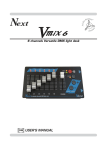
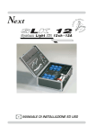
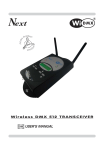
1
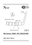
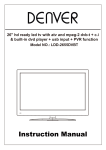
Next
12/24 channels Versatile DMX light desk
Next
1
12/24 channels Versatile DMX light desk
2
3
4
5
6
7
8
9
10
11
12
CHASE
SPEED
2 3 4
1
6
MIC
0.8
10
10
10
A
9
8
7
6
5
4
3
2
1
0
9
9
8
8
7
7
6
6
5
5
4
4
3
3
2
2
1
1
0
0
10
10
B
9
8
7
6
5
4
3
2
1
0
1
2
3
4
5
6
CHASE
> EDIT
10
9
8
7
7
7
6
6
6
5
5
5
4
4
4
3
3
3
2
2
1
0
11
12
SCENE
MONITOR
> GRAB
OUTPUT
MAN
AB
10
PAGE
> COPY
10
10
GB
CHASE 2
CHASE 3
USER’S MANUAL
CHASE 4
10
10
9
9
9
9
9
8
8
8
8
8
7
7
7
7
7
6
6
6
6
6
5
5
5
5
5
4
4
4
4
4
3
3
3
3
3
2
2
2
2
2
2
1
1
1
1
1
1
1
0
0
0
0
0
0
0
A
B
CHASE
CHASE 1
16
0
FLASH
8
10
8
2
SOLO
9
9
SEC
XFADER
8
8
4
4
10
12
MUSIC
9
7
8
0.4
STEP
STEP
> LENGTH
10
FADE
TIME
MIN
16 32 1
2
8
GO
MASTER
GB
We congratulate you on your purchase of V-MIX 2000. Before
proceeding of the use of this product it should be necessary to read
carefully the following user’s manual to install it correctly and to make
the most of its potentialities.
FRONT PANEL
GB
Next
12/24 channels Versatile DMX light desk
1
1
2
3
4
5
6
10
7
8
9
10
11
12
10
10
A
9
8
7
6
5
4
3
2
1
0
9
9
8
8
7
7
6
6
5
5
4
4
3
3
2
2
1
1
0
0
2
3
10
10
10
B
9
8
7
6
5
4
3
2
1
0
1
2
3
4
5
9
9
8
8
7
7
6
6
5
5
4
4
3
3
2
2
1
1
0
0
6
7
4
8
9
10
11
12
CHASE 1
CHASE 2
CHASE 3
CHASE 4
1
OUTPUTS MONITOR
2
12 UP FADERS “A”
3
12 DOWN FADERS “B”
4
12 FLASH KEYS
5
FADE TIME KNOB
6
SPEED KNOB
7
MUSIC KEY
8
CHASE/EDIT KEY
9
STEP/LENGTH KEY
5
6
CHASE
SPEED
2 3 4
1
6
MIC
0.8
FADE
TIME
MIN
16 32 1
8
2
8
0.4
STEP
4
10
SEC
4
2
8
0
12
16
10
FLASH
SOLO
7
11
XFADER
MUSIC
8
12
9
CHASE
> EDIT
SCENE
MONITOR
STEP
ENGTH
10
16
AB
17
10
14
> GRAB
OUTPUT
MAN
15
13
PAGE
> COPY
18
10
10
10
10
9
9
9
9
9
8
8
8
8
8
7
7
7
7
7
6
6
6
6
6
5
5
5
5
5
4
4
4
4
4
3
3
3
3
3
2
2
2
2
2
2
1
1
1
1
1
1
0
0
0
0
0
0
9
8
7
6
5
4
3
A
SCENE MODE FLASH/SOLO/XFADER KEY
11
SCENE/MONITOR KEY
12
MAN KEY
13
PAGE/COPY KEY
14
GRAB KEY
15
PRESET A FADER
16
PRESET B FADER
17
CHASE FADER
18
MASTER FADER
19
PRESET A KEY
20
PRESET B KEY
B
CHASE
GO
19
10
20
MASTER
USER’S MANUAL
GB
Sets of the equipment
1.1 Unpacking of the equipment
1.2 Acessories issued with the equipment and relative documentation
Description of the rear panel and installation
2.1 Description of the rear panel
2.2 DMX 512 output connection
2.3 Input connection for power supply
2.4 Connection of the ballast to the electric system
Use of the equipment - modes of operation
3.1
3.2
3.3
3.4
24 Channels SINGLE PRESET ( WIDE ) Operation
12 Channels DOUBLE PRESET Operation
MAN Operation
“ GO ” Function
4.1
4.2
4.3
4.4
4.5
4.6
4.7
4.8
4.9
GRAB Function
REGISTER OF MEMORY (SCENE) mode
FLASH Operation
SOLO Operation
XFADER Operation
Modification of the REGISTER OF MEMORY
DIRECT Function
PAGE Function
PAGE COPY Function
5.1
5.2
5.3
5.4
5.5
CHASE Section
CHASE Function
LENGTH Function
EDIT CHASE Function
MUSIC Function
6.1 Example of working
6.2 Copy of the registers
GB
1.1 Unpacking of the equipment
Open the box; take the ballast and the documentation out.
Take the equipment out of the box as shown in the picture below.
Next
1
2
12/24 channels Versatile DMX light desk
3
4
5
6
7
8
9
10
11
12
CHASE
SPEED
MIC
2
FADE
TIME
3 4
16 32 1
1
6
0.8
10
10
10
A
B
10
2
2
1
1
0
0
1
2
3
4
5
6
7
8
9
10
11
12
1
0
10
10
9
10
9
7
7
6
6
5
5
4
4
3
3
2
1
0
8
8
7
6
5
4
3
2
1
9
8
8
7
6
5
4
3
0
10
9
9
8
7
6
5
4
3
2
2
1
0
PR-A
COPY
10
AB
9
8
7
6
5
4
3
PAGE
MAN
>WIDE
10
8
7
6
5
4
3
2
1
16
0
SCENE
>MEM
STEP
>MEM
10
9
9
8
7
6
5
4
3
0
CHASE
>LENGTH
1
0
10
9
8
7
6
5
4
4
8
2
SOLO
XFADER
MUSIC
2
1
0
3
MIN
2
8
SEC
FLASH
7
6
5
4
3
2
2
1
4
10
12
8
8
7
6
5
4
3
0
8
0.4
STEP
9
9
9
8
7
6
5
4
3
2
2
1
0
1
0
PR-B
CHASE
MASTER
1.2 Acessories issued with the equipment and relative documentation
Verify the contens of the packing.
If one of the following parts of the packing is missing or damaged, please,
contact your dealer immediately.
A) User’s manual
B) VM2K Ballast
A
B
2.1 Description of the rear panel and installation
2
1
1
4
2
3
1
2
3
4
5
=
=
=
=
=
COMMON
DATA DATA +
n.c.
n.c.
DMX 512
OUTPUT
POWER INPUT
12 VDC - 6 W
1
5
3
3
2
AUDIO IN
(0 dB)
4
COMMON
2
5
+VDC
1
OFF
PUSH
POWER
ON
GB
3
4
1
Power key
2
12 Vdc power INPUT with a 3-pin cannon connector.
3
0 dB audio signal INPUT with a mono/stereo jack connector.
4
Standard DMX 512 signal OUTPUT with a 5-pin cannon connector.
2.2 DMX 512 OUTPUT CONNECTION
Make sure you are using a shielded twisted cables suitable for the
transmission of the DMX 512 signal with connectors of good quality and
connection as shown on the side of the connector.
Plug the 5-pin cannon connector coming from the dimmer completly in the
DMX 512 output
4
Use the “push” safety hook to disconnect it and than extract it gently.
ATTENTION: the shielded part of the cable must never be connected to
the ground of the electrical system as this could cause faults during the
working of the controller.
THE DMX CHANNEL OUT ARE:
N° 1/12 DOUBLE PRESET MODE
N° 1/24 SINGLE PRESET MODE (WIDE)
2.3 Input connection for power supply
GB
Plug the 3-pin cannon connector of the ballast completly in the power
input 2
Use the “push” safety hook to disconnect it and extract it gently.
ATTENTION: do not use ballast different from the one supplied, it could
cause serious damages at the internal circuitation.
Do not connect the 3-pin cannon connector in other appliances, it has
been studied to be used only in this controller.
2.4 Connection of the ballast to the electric system
MAKE SURE THAT VOLTAGE AND POWER FREQUENCY CORRESPOND
TO WHAT IS REPORTED ON THE BALLAST PLATE.
The supplied ballast has a plug, therefore you should only plug it in the
socket.
Press Power key
1
to verify the correct installation.
If pressing the Power key no one led light up, please check if there is
tension in the electric socket or check the connection between ballastcontroller and ballast-electric socket.
If the problem persist, please consult your dealer.
GB
INITIAL INFORMATION
The Vmix factory default mode is 12 channels DOUBLE PRESET operation..
3.1 Activation of 24 Channel single preset mode (WIDE)
This procedure allows to go in 24 channels single preset operation.
-Turn off the V-MIX through Power key placed on the rear.
-Hold pressed the MAN key (Fig.1) and Turn on the V-MIX through MAN
Power key placed on the rear at the same time.
> LENGTH
Now the Mixer is ready to work in 24 channels
SINGLE PRESET operation.
Fig. 1
3.2 Activation of 12 Channel double preset
This procedure allows to go in 12 channels double preset operation.
-Turn off the V-MIX through Power key placed on the rear.
-Hold pressed the SCENE key (Fig.2) and Turn on the V-MIX SCENE
through Power key placed on the rear at the same time.
> LENGTH
Now the Mixer is ready to work in 12 channels
DOUBLE PRESET operation.
Fig. 2
3.3 MAN operation
GB
This function allows to modify manually each output single channel
Pressing MAN key the PRESET MANUAL function is
activated (Fig.3)
Fig. 3
MAN
The activation of the function has signalled from the red> LENGTH
light to side of the same key.
USE OF MASTER FADER:
The MASTER fader checks the general level of the output channels.
Keep the MASTER fader to the maximum.
Keep the PRESET A fader to the maximum.. (100%) and the PRESET B
fader to the zero value, through the PRESET A fader you can control the
general level of the preset A. The 12 upper fader control the single intensity
of the channels of the preset A.
Keep the PRESET A fader to zero value.. and the PRESET B fader to the
maximum.. (100%), through the PRESET B fader you can control the general level of the preset B. The 12 upper fader control the single intensity of the
channels of the preset B.
Through the two A and B PRESET faders is possible to mix between them
the channels of the preset A with those of the preset B.
In WIDE operation (24 channels) the up faders control the 1/12 channels,
and the down faders control the 13/24 channels.
The PRESET A fader control the general level of the 24 channels of the
A+B presets.
The output monitor show one of the two banks (12 channels each one);
PRESET A key = 1/12 channels; PRESET B key = 13/24 channels.
USE OF FLASH KEYS:
The 12 keys that are under down faders keep the output 1/12 channel to the
maximum value (100%).
In WIDE operation the FLASH keys correspond to the output monitor;
PRESET A key = 1/12 channels; PRESET B key = 13/24 channels.
3.4 “GO” function
When you are using the PRESET MANUAL function
MAN) you can activate the automatic mixing between
(M
GO function).For the activathe two A and B presets (G
tion of the function is essential that one of the two preset is active in output (100%) while the other is to zero
value.
Pressing at the same time the two under keys the PRESET A a n d B f a d e r s ( F i g . 4 ) y o u a c t i v e t h e GO
function;the level of the active preset at 100% begin to
descend to the zero value while the level of the preset
don't activate salt to the maximum value.You can set
the time of passage between the two presets through
the FADE TIME knob (Fig.5).
During this passage the XFADER light flashes to point
out that the GO function is active, while the green indicator to the side of the PRESET A and B keys points
out the DESTINATION preset, that is what at the end of
the passage will be in output at 100%.
In any moment is possible intervene in manual way on
the level of the incoming preset and on the level of the
closing preset, intercepting through the two PRESET A
and B faders the actual levels.
As soon as intercepted the level of entry or of gone out
the automatic function comes disabled and the control
becomes manual.
In WIDE operation the GO function is inactive.
GB
10
9
8
7
6
5
4
3
AB
10
9
8
7
6
5
4
3
2
2
1
1
0
0
A
B
GO
Fig. 4
FADE
TIME
MIN
16 32 1
2
8
4
4
SEC
Fig. 5
8
2
0
16
4.1 GRAB function
The GRAB function allows to memorize the state of the
channels of output (SCENE) in one of the 12 registers
of memory or the CHASE currently active (and his
speed of slide).
You also see: 6.1 Example of working / 6.2 Copy of the registers
GB
> GRAB
OUTPUT
Fig. 6
•••••••••••••••••••••••••••••••••••••••••••••••••••••••••••••••••••••
Memorization of the state of the channels of output (SCENE) in a register of memory
•••••••••••••••••••••••••••••••••••••••••••••••••••••••••••••••••••••
PRELIMINARY OPERATIONS:
- Keep the PRESET A, PRESET B and MASTER faders to the maximum.. (100%)
- Keep the CHASE fader to zero value (the light on channels of CHASE, if
active, won't have memorized in the SCENE).
- Create in output the scene that you want to memorize (in any operational formality).
- Now in the outputs monitor and in output you will have a preview of the SCENE.
- Press for over 1 second the GRAB key (Fig.6). ( the GRAB + SCENE red lights must flash)
- On the outputs monitor comes automatically selected the register of active memory.
- Select, if different from the active one, the register of memory on which memorize the
SCENE.
- Press the GRAB key (Fig.6) for confirm and conclude the copy, otherwise
another key for get out of the copy, with no modification.
•••••••••••••••••••••••••••••••••••••••••••••••••••••••••••••••••••••
Assignment of the CHASE currently active to a register of memory (9,10,11,12 only registers):
•••••••••••••••••••••••••••••••••••••••••••••••••••••••••••••••••••••
PRELIMINARY OPERATIONS:
- Keep the PRESET A and PRESET B faders to zero value.
- Keep the CHASE and MASTER faders to the maximum.. (100%).
- Select through the CHASE function (Par. 5.2) the chase to memorize (in
any operational formality).
- Regulate the speed desired through the SPEED knob (also the speed will
come memorized).
- Now in the outputs monitor and in output you will have a preview of the CHASE.
- Press for over 1 second the GRAB key (Fig.6). ( the GRAB + CHASE red
lights must flash)
- On the outputs monitor comes automatically selected the register of active
memory (9/12).
- Select, if different from the active one, the register of memory on which
memorize the CHASE.
- Press the GRAB key (Fig.6) for confirm and conclude the copy, otherwise
another key for get out of the copy, with no modification.
THE REGISTERS OF MEMORY ARE NOT
MEMORIZED, THEY CONTAIN EMPTY SCENES.
FOR ASSIGN A SCENE OR A CHASE TO REGISTERS OF
MEMORY CONSULT THE PARAGRAPHS:
- 4.1 GRAB FUNCTION
- 6.1 EXAMPLE OF WORKING
4.2 REGISTER OF MEMORY (SCENE) mode
GB
Pressing SCENE key the SCENE function is activated. (Fig.7)
Fig. 7
The activation of the function has signalled from
the red light to side of the same key.
The 12 lower faders (B) become REGISTERS Of MEMORY,
now each of them doesn't control more a single channel,
but a memory.
SCENE
> LENGTH
FLASH
Each memory could contain a SCENE or a CHASE (only for
9-12 memorys).
SOLO
XFADER
Fig. 8
SEE GRAB FUNCTION (Par 4.1)
The 12 upper faders (A) become faders of MODIFICATION and each of them
checks a single channel of the scene in output.
Keep the PRESET A and B fader to the maximum. (100%).
The PRESET A fader control the general level of the modification done by 12
upper faders.
The PRESET B fader control the general level of the registers of memory in
output.
Through the SCENE MODE key set above the SCENE key are activated the three
operational ways in sequence:(Fig.8)
FLASH: Par 4.3
SOLO: Par 4.4
XFADER: Par 4.5
4.3 FLASH operation
GB
In this operational way the initial position of the 12 faders is zero.
Each register of memory (lower faders 1/12 fig.9) command a memory in
output; it is possible add more memories simply moving the corresponding
fader.
The 12 FLASH keys under the lower faders (fig.9) keep the value of the register of memory 1/12 to the maximum value.
in WIDE operation the outputs monitor visualizes through the PRESET A key
the channels 1/12; through the PRESET B key the channels 13/24..
4.4 SOLO operation
The SOLO operation is the same to the FLASH operation except that for the
function of the FLASH keys.
The 12 FLASH keys under the lower faders (fig.9) keep the value of the register of memory 1/12 to the maximum excluding all the other registers of active memory, therefore
you have in output ONLY that memory till that you hold pressed the FLASH key..
10
10
10
B
9
8
7
6
5
4
3
2
1
0
1
2
3
4
5
Fig. 9
6
9
9
8
8
7
7
6
6
5
5
4
4
3
3
2
2
1
1
0
0
7
8
9
10
11
12
CHASE 1
CHASE 2
CHASE 3
CHASE 4
FADE
TIME
MIN
16 32 1
8
2
4
SEC
4
2
Fig. 10
8
0
16
4.5 XFADER operation
In this operational way the initial position of the 12 faders is at the maximum(100%);
and only one register of memory at a time is active in output.
For activate one of the 12 registers of memory you must verify that the cursor
is to the maximum (100%) and select the correspondent FLASH key (Fig.9) that
in this case acts from key of selection of the register in output.
The time of passage between two registers is adjustable from the FADE
TIME knob (Fig.10); during the passage the XFADER red light flashes.
If you want to dissolve the register of memory currently active in output,
press again the correspondent key of activation.
Pressing the SCENE key, on the outputs monitor you see the number of the
register currently active, for return to visualize the levels of output press it
again.
In WIDE operation the outputs monitor visualizes through the PRESET A key
the channels 1/12; through the PRESET B key the channels 13/24..
4.6 Modification of the Register of Memory
GB
IN THE FLASH/SOLO/XFADER MODE Through the 12
upper faders (A) is possible to modify the value of the single channels that they compose the SCENE in output.
SCENE
> LENGTH
MAKE SURE TO HAVE ACTIVATED THE SCENE MODE OPERATION (Fig.11).
IT IS NOT POSSIBLE TO MODIFY REGISTERS CONTAINING A CHASE.
Fig.11
Keep the PRESET A and B fader to the maximum. (100%).
Through the 12 upper faders (A) is possible to modify the value of the single channels that they compose the SCENE in output.
With the fader is necessary "hook" (catch mode) the value of output of each channel
and keep it to the desired level.
The PRESET A fader control the general level of the modification done.
The PRESET B fader control the general level of the registers of memory in output.
When you keep the PRESET A fader to the zero value the modified channels remain to zero
For restore the values of the REGISTER OF MEMORY keep it to zero value.
When you keep ALL the REGISTER OF MEMORY to the zero value all the modified
channels will go to zero level
For save in memory in a permanent way the made modifications you must press for
over 1 second the GRAB key, automatically the software will select the register of
memory in use and will visualize it on the outputs monitor.
To select another register, between the twelve available, press one of the 1/12 FLASH keys..
Press the GRAB key again to save the modifications you done,, otherwise another key
for get out of the function, with no modification.
The modified scene could be used also without have memorized, the modifications
will stay active till that the corresponding fader doesn't come kept to zero value.
In WIDE operation the outputs monitor and the faders of modification are relative to
the channels 1/12 through the PRESET A key,
while they will be relative to the channels 13/ 24 through the PRESET B key..
4.7 DIRECT function
MAKE SURE TO HAVE ACTIVATED THE SCENE MODE OPERATION (Fig.11)
The DIRECT function allows to select 12/24 channels with manual control
The DIRECT function is activated pressing for two second
the MUSIC key. (Fig.11/B)
The activation of the function has signalled from the
flashes of the green light to side of the same key.
MUSIC
> DIRECT
Fig. 11/B
When the DIRECT function is activated,on the outputs monitor you see the
channels with manual control currently active; for select a different one,
between the twelve available, press one of the 1/12 FLASH keys..
In WIDE operation the outputs monitor and the faders of manual control are
relative to the channels 1/12 through the PRESET A key,
while they will be relative to the channels 13/ 24 through the PRESET B key..
4.8 PAGE function
GB
This function allows to select the page of active memory between the 12
available
Pressing PAGE key the PAGE function is activated. (Fig.12)
The activation of the function has signalled from the
red light to side of the same key.
PAGE
> COPY
Fig. 12
On the outputs monitor you see the page currently active;
for select a different one, between the twelve available, press one of the 1/12
FLASH keys..
Press another key for get out of the copy, with no modification.
THE V-MIX 2000 CONTAINS 12 REGISTERS OF MEMORY FOR EACH PAGE .
THE PAGES OF MEMORY ARE 12.
IN TOTAL IT IS POSSIBLE HAVE 144 REGISTERS OF AVAILABLE MEMORY.
NOTE:
THE REGISTERS OF MEMORY CURRENTLY ACTIVE IN OUTPUT (the regis ters in the SCENE operation with the faders different from zero) ALWAYS
MAINTAIN PRIMARY PAGE.
ONLY THE REGISTERS THAT COME KEPT TO ZERO VALUE ARE
ADJOURNED WITH THE NEW PAGE OF MEMORY .
4.9 PAGE COPY function
This function allows to copy a whole page of
The Registers of memory 1-12 comes copied in an other page.
memory.
USE THIS FUNCTION WITH CAUTION!!.
THE PRECEDING CONTENT OF THE PAGE OF MEMORY OF DESTINATION IS
CANCELED AND THE DATA COME LOST
The PAGE COPY function is activated pressing for two
second the PAGE key. (Fig.13)
The activation of the function has signalled from the
red light to side of the same key.
PAGE
> COPY
Fig. 13
On the outputs monitor you see the page currently active;
for copy it in an other, between the twelve available, press one of the 1/12
FLASH keys..
Press another key for get out of the copy, with no modification.
5.1 CHASE SECTION
GB
A CHASE is a play of lights, he is made of a sequence of steps
(from 1 to 12 max).
The CHASE fader (Fig.14) checks the level of output of the CHASE
currently active; keep the CHASE fader to the maximum (100%)
Through the SPEED knob (Fig.15) you
can regulate the speed of the currently active CHASE (the time of passage
between the steps of the same
chase).
CHASE
SPEED
2 3 4
1
6
0.8
0.4
STEP
10
10
9
9
8
8
7
7
6
6
5
5
4
4
3
3
2
2
1
1
0
0
8
CHASE
10
12
Fig. 14
Fig. 15
5.2 CHASE function
The C H A S E function allows to select the C H A S E
active.
The CHASE fader (Fig.14) checks the level of output of the
CHASE currently active; keep the CHASE fader to the maximum
CHASE
> EDIT
Fig. 16
Through the SPEED knob (Fig.15) you can regulate the speed of the currently active CHASE (the time of passage between the steps of the same chase).
Pressing the CHASE key, on the outputs monitor you see the CHASE currently active; for select a different one, between the twelve available, press
one of the 1/12 FLASH keys..
Press another key for get out of the copy, with no modification.
5.3 LENGTH function
The LENGTH function allows to select the last step of the CHASE currently active.
The LENGTH function is activated pressing for two second the STEP key. (Fig.17)
The activation of the function has signalled from the red
light to side of the same key.
STEP
> LENGTH
Fig. 17
Pressing the LENGTH key, on the outputs monitor you see the last step of
the CHASE currently active; for select a different one, between the twelve
available, press one of the 1/12 FLASH keys..
Press another key for get out of the copy, with no modification.
Each CHASE is a whole of steps (from 1 to 12 max) in sequence, when arrive to the
last step, it restart from the first. For motives of synchronism between the last step
and the first is at times necessary that the last is different from 12.
GB
5.4 EDIT CASE function
The EDIT CHASE function allows to modify the single steps of the CHASE
currently active.
The EDIT CHASE function is activated pressing for two
second the CHASE key. (Fig.18)
The activation of the function has signalled from the red
light to side of the same key.
CHASE
> EDIT
Fig. 18
Through the SPEED knob you see, in any moment, the preview of the CHASE.
Only rotating this knob on the left, on the STEP position is possible to modify
the step (the STEP red light turn on).
Through the 12 upper faders is possible to modify the value of the single
channels that they compose the step, through the FLASH keys 1/12 turn
on/off one of the 12 channels in a rapid way.
For see and to modify the following step press the STEP key.
Pressing the SCENE key, on the outputs monitor you see the number of the step currently active, for return to visualize the levels of output press it again.
For finish the modification of the steps of the CHASE, press the CHASE key.
To modify the number of steps that they compose the CHASE you see
LENGTH function (par 5.3)
NOTE. ALL THE MODIFICATIONS TO THE LEVELS WILL COME HOWEVER MEMORIZED.
In WIDE operation the outputs monitor and the faders of modification are
relative to the channels 1/12 through the PRESET A key,
while they will be relative to the channels 13/ 24 through the PRESET B key..
5.5 MUSIC function
The MUSIC function allows to activate the advancement of
the steps of the CHASE to rhythm of music.
MUSIC
The MUSIC function is activated pressing the MUSIC key. (Fig.19)> LENGTH
The activation of the function has signalled from the green
light to side of the same key.
Fig. 19
Through the SPEED knob is possible vary the sensibility of the musical sensor.
The musical sensor receives the audio signal from the rear audio input or from
the built-in microphone. (If to the rear input you connect a jack the built-in
microphone is deactivated).
The input music signal is a 0dB mono/stereo so it could be taken from sound
sources like Mixer, CD, Dat etc.
IT IS ABSOLUTELY FORBIDDEN TO CONNECT TO THIS INPUT ANY POWER SIGNALS
FOR ACOUSTIC SPEAKER COMING FROM AMPLIFIED MIXER OR AMPLIFIER!!
GB
6.1
Example of working
I
GB
The V-MIX 2000 thanks to his evolved software simplify notably all the functions of use and
progamming.
EXAMPLE OF CREATION OF A SCENE AND TRANSFER TO A REGISTER OF MEMORY.
- Keep the MASTER fader and PRESET A/B to the maximum and the CHASE fader to zero.
- Activate the MAN operation and create in output the SCENE desired through the faders.
Slight
CENdesk
E to transfer.
- Now in output you have
thechannels
preview
of the
12/24
Versatile
DMX
- Press for over 1 second the GRAB key.
- The GRAB function know that you are memorizing a SCENE (the GRAB and SCENE red lights
to side of the same keys flashes).
- The OUTPUT MONITOR show the number of the register in use.
- Select through the 1/12 FLASH keys the register of destination of the SCENE (is not
1
4that currently
5
6 in use).
7
8
9
10
11
12
necessary select
it if2is the 3
same of
- Press GRAB key for memorize the SCENE in the selected register.
- Now the selected register contains the SCENE; for use the registers go to SCENE operation.
Next
EXAMPLE OF MODIFICATION TO A REGISTER OF MEMORY IN SCENE MODE.
- Keep the MASTER fader to the maximum.. and the CHASE fader to zero..
- Keep the PRESET A and B fader to the maximum. (100%).
- The PRESET A fader control the general level of the modification done by 12 upper
faders.
- The PRESET B fader control the general level of the registers of memory in
output.
- Activate the SCENE mode and recall in output the desired SCENE (one or more).
In the XFADER operation only one scene at a time is active in output through the FLASH keys
(keep the FADE TIME knob to zero otherwise wait the flash of the XFADER red light stop).
- To modify each single channel through the 12 upper faders; "hook" (catch mode) the value
of output of each channel and keep it to the desired value .
- Now you have the preview of the SCENE to transfer.
- Press for over 1 second the GRAB key.
- The GRAB function know that you are modifying a SCENE (the GRAB and SCENE red lights to
side of the same keys flashes).
- Press GRAB key for memorize the SCENE modified.
10
9
8
7
6
5
4
3
2
1
0
10
9
8
7
6
5
4
3
2
10
A
9
8
8
7
7
6
6
5
5
4
4
3
3
2
2
1
1
0
0
10
B
0
10
9
9
8
8
7
7
6
6
5
5
4
4
3
3
2
2
1
1
0
0
EXAMPLE OF TRANSFER OF ACTIVE CHASE IN A REGISTER OF MEMORY;
(ONLY REGISTER 9 - 10 - 11 - 12).
- Keep the MASTER and CHASE fader to the maximum PRESET A and PRESET B to zero.
2
3 and 4
5 chase
6 desired
7
8
9 CHASE
10 function.
11
12
MAN operation
- Activate the 1
select the
through
the
- Regulate the desired speed of CHASE through SPEED knob.
- Now you have the preview of the CHASE to transfer.
CHASE 1
CHASE 2
CHASE 3
CHASE 4
- Press for over 1 second the GRAB key.
- The GRAB function know that you are memorizing a CHASE (the GRAB and CHASE red lights
to side of the same keys flashes).
- The OUTPUT MONITOR show the number of the register in use.
- Select through the 9/12 FLASH keys the register of destination of the CHASE (is not
necessary select it if is the same of that currently in use).
- Press GRAB key for memorize the CHASE in the selected register.
- Now the selected register contains the CHASE; for use the registers go to SCENE operation
1
10
9
GB
6.2 Copy of the registers
COPY OF THE SCENE CONTAINED IN A REGISTER IN AN OTHER REGISTER
- Keep the MASTER and PRESET A faders to the maximum and the CHASE fader to zero..
- Activate the SCENE mode and recall in output the desired SCENE to copy..
- Press for over 1 second the GRAB key.
- The OUTPUT MONITOR show the number of the register in use.
- Select through the 1/12 FLASH keys the register where you want to copy the SCENE.
- Press GRAB key for memorize the copy..
- Now the selected register contains the copy of the SCENE.
MIC
COPY OF THE SCENE CONTAINED IN A REGISTER IN AN OTHER REGISTER
OF A PAGE OF MEMORY DIVERGED FROM THAT IN USE.
- Keep the MASTER and PRESET A faders to the maximum and the CHASE fader to zero..
- Activate the SCENE mode and recall in output the desired SCENE to copy..
CHASE
FADE
F M E M O R Y of destination of the copy through the PAGE
SPEED
- Select
the P A G E OTIME
MIN
16 32 1
2 3 4
Function.
1
6
8
2
- Press0.8for over 1
8 second
4 the GR4AB key.
8 number of the register in use.
0.4
10
OR 2show the
- The OUTPUT MONITSEC
0
16
STEP
12
- Select through the
FLASH1/12 FLASH keys the register where you want to copy the SCENE .
SOLO
- Press GRAB key for memorize the copy..
XFADER
MUSIC
- Now the selected register contains the copy of the SCENE.
- The page currently in use has become that of destination.
CHASE
> EDIT
STEP
ENGTH
10
9
8
7
6
5
4
3
2
1
0
SCENE
PAGE
USE OF TH
E GRAB FUNC>
TICOPY
ON
MONITOR
The GRAB function is of fundamental importance for the progamming of the V-MIX
2000; but
made extremely simple.
> GRAB
MANhis use has
OUTPUT
It is main point remember that the GRAB function captures all the levels of output
and it transfers them in a register of memory; it allows to memorize the exact
present scene in output.
AB
10
10
10
10
10
9
9
9
9
9
8
8
8
8
8
7
7
7
7
7
6
6
6
6
6
5
5
5
5
5
4
4
4
4
4
3
3
3
3
3
2
2
2
2
2
1
1
1
1
1
0
0
0
0
0
It’s indifferent in the way in which you have created that scene.
What comes memorized is exactly what you see on the outputs monitor and on the
stage.
THE LEVELS OF OUTPUT GIVEN BIRTH TO THE CHASE DOESN'T COME MEMORIZED,
THEREFORE IT IS ADVISABLE KEEP TO ZERO THE CHASE FADER DURING THE GRAB
FUNCTION.
A
B
CHASE
GO
MASTER
Technical features
Technical features: programming
Number of channels controlled separately: 12/24 (WIDE)
Double preset/Single preset (WIDE)
Number of register for any page: 12 containing SCENE/CHASE
Total page of memory: 12
Total memory’s scene: 144
Number of CHASE in MEMORY: 12 (modifiable)
Number of STEP for any CHASE: MAX 12, LEVEL or ON/OFF types
Total Number of the executable CHASE at the same time : 5
Technical features: output signal
Kind of output signal: DMX512/ 1990
Output connector: 5-pin cannon connector
Max number of dimmer connected to the DMX output: 32
Number of DMX channels: 12 (24 ch. WIDE mode)
Technical features: storage of settings
Kind of storage / size: EEPROM / 64 Kbit
Length of data maintenance without power supply: > 40 years
Number of entries cycles: >10.000.000
Climatic condition for the use
Humidity: 35% ÷ 80%
Temperature: 5 ÷ 50 °C
Power supply
Voltage/current: 12 Vdc / 240 mA
Technical features: audio input
Source: Inside through a built-in microphone / outside through a stereo jack
Sensitivity / input impedance: 0 dB (775 mV) / 50 Kohm
Kind of level adjustment: Automatic
Dimensions and weight
Dimension (W x L x H) / Weight: 482 x 370 x 45 mm / 5 Kg.
GB
CODEM MUSIC S.r.l. - Via Del Vallo, 110 - 61100 PESARO - ITALY
Tel. +39 0721 204357- Fax +39 0721 203554
http://www.codemmusic.com - E-mail: [email protected]
All rights reserved. No parts of this document can be copied, photocopied or reproduced without
the prior written permission of the CODEM MUSIC s.r.l.
No responibility is taken for possible inaccuracies or mistakes.
The CODEM MUSIC s.r.l. reserves the right to make any alterations or aesthetics changes of this
product that seem necessary at any time and for whatever reason.
The CODEM MUSIC s.r.l. takes no responsibility for the use or for the application of this product.
GB