1
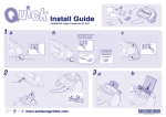
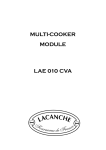
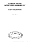
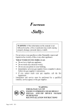
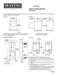
LACANCHE KITCHEN RANGE
HOODS
L2HM 900 - L2HM 1000 - L2HM 1100 - L2HM 1200
L2HM 1300 - L2HM 1500 - L2HM 1600 - L2HM 1700
L2HM 1700 - L2HM 1800 - L2HM 2000 - L2HM 2100 - L2HM 2200 - L2HM 2400
Hottes - Ft 118a - GB - Rév 08 - Modifié le : 06/07/2015
1/28
TECHNICAL DATA SHEETS, MEASUREMENTS AND DIMENSIONS
—————————————————————————————————————————3
INSTALLER’S MANUAL
7
SITTING
—————————————————————————————————————————9
SETTING UP THE HOOD
—————————————————————————————————————————13
SETTING UP OF GROUPS
—————————————————————————————————————————17
INSTALLING THE EXTRACTOR HOOD EXTENSION
—————————————————————————————————————————20
INSTALLING MOUNTING CHANNEL COVERS
—————————————————————————————————————————22
USER’S MANUAL
23
USE
—————————————————————————————————————————25
CLEANING AND MAINTENANCE
—————————————————————————————————————————26
Note concerning the disposal of waste electrical and electronic equipment
—————————————————————————————————————————28
Hottes - Ft 118a - GB - Rév 08 - Modifié le : 06/07/2015
2/28
TECHNICAL DATA SHEETS, MEASUREMENTS
AND DIMENSIONS
495
L
305 - Axe de sortie centrale
Hotte LHM
225 - Axe de sortie centrale
Hotte LHME
Axe de sortie murale
Hotte LHME
Raccordement électrique
Hotte LHM - LHME
Axe de sortie murale/centrale
Hotte LHM - LHME
580
165
0 à 240
155 90
Axe de sortie murale
Hotte LHM
890
750
2400
15
650
1820
40
725
70
100
930
596
A
B
INSTALLER’S MANUAL
900
1000
1100
1200
1300
1500
1600
1700
1800
2000
2200
2400
385
485
585
685
785
985
1085
1185
1285
1485
1685
1885
80
B
.5~
73
L2HM 900
L2HM 1000
L2HM 1100
L2HM 1200
L2HM 1300
L2HM 1500
L2HM 1600
L2HM 1700
L2HM 1800
L2HM 2000
L2HM 2200
L2HM 2400
A
Hottes - Ft 118a - GB - Rév 08 - Modifié le : 06/07/2015
3/28
TECHNICAL DATA SHEETS, MEASUREMENTS
AND DIMENSIONS
LACANCHE KITCHEN RANGE HOODS
- Decorative single and double blower unit kitchen range hoods in canopy widths from 900 to 2 000 mm.
CAUTION :
Under no circumstances shall the distance between the exhaust hood and the wall or
ceiling exhaust opening exceed 9 metres.
Make sure that the support surface and fixings used are able to take the weight of
the hood.
Before drilling any holes, make sure that there are no electric cables, gas pipes or
other ducts or piping running through the wall (in the areas concerned).
As far as possible, it is advisable to mount the hood on a solid support surface.
- Stainless steel or black, white or color epoxy-coated shell.
- Adjustable duct cover.
- Single (L2HM 90-1100) or double blower units (other models), featuring.
- Max. sound levels of 52 dB(A) (at 1 m of unit).
- Top or side exhaust.
Blowers
Blower units
1
1
Exhaust duct
diameter
125 mm
125 mm
L2HM 900
L2HM 1000
874
874
327 m3/ 384 Pa
327 m3/ 384 Pa
L2HM 1100
L2HM 1200
L2HM 1300
L2HM 1500
L2HM 1600
L2HM 1700
874
878
878
878
878
874
1
1
1
1
1
2
125 mm
150 mm
150 mm
150 mm
150 mm
2 x 125 mm
327 m3/ 384 Pa
627 m3/ 383 Pa
627 m3/ 383 Pa
627 m3/ 383 Pa
627 m3/ 383 Pa
654 m3/ 384 Pa
L2HM 1800
L2HM 2000
L2HM 2100
L2HM 2400
874
874
874
878
2
2
2
2
2 x 125 mm
2 x 125 mm
2 x 125 mm
2 x 150 mm
654 m3/ 384 Pa
654 m3/ 384 Pa
654 m3/ 384 Pa
1254 m3/ 383 Pa
L2HM 900 E
L2HM 1000 E
810
810
1
1
150 mm
150 mm
576 m3/ 380 Pa
576 m3/ 380 Pa
L2HM 1100 E
L2HM 1200 E
L2HM 1300 E
L2HM 1400 E
L2HM 1500 E
L2HM 1600 E
L2HM 1700 E
810
820
820
820
820
820
820
1
1
1
1
1
1
1
150 mm
150 mm
150 mm
150 mm
150 mm
150 mm
150 mm
576 m3/ 380 Pa
655 m3/ 364 Pa
655 m3/ 364 Pa
655 m3/ 364 Pa
655 m3/ 364 Pa
655 m3/ 364 Pa
655 m3/ 364 Pa
L2HM 1800 E
L2HM 2000 E
L2HM 2100 E
L2HM 2400 E
810
810
810
820
2
2
2
2
2 x 150 mm
2 x 150 mm
2 x 150 mm
2 x 150 mm
1152 m3/ 380 Pa
1152 m3/ 380 Pa
1152 m3/ 380 Pa
1310 m3/ 364 Pa
INSTALLER’S MANUAL
Hottes - Ft 118a - GB - Rév 08 - Modifié le : 06/07/2015
4/28
TECHNICAL DATA SHEETS, MEASUREMENTS
AND DIMENSIONS
Connecting exhaust duct :
Attention: Cut exhaust duct(s) and make sure duct, when run through the hole in the base of the installed
hood protrudes far enough to be connected to the fan(s).
Electric connection :
Finish cable with an earthed 2-pole plug suitable for 230V/1N~/50Hz.
Hood must be earthed.
Power input :
- L2HM 900 - 1100 : 120 Watt when lit.
- L2HM 1101 à 1601 : 235 Watt when lit.
- L2HM 1701 à 2002 : 240 Watt when lit.
- L2HM 2102 à 2202 : 470 Watt when lit.
Directives :
Low Voltage : 2006/95/CEE
CEM : 2004/108/CEE
INSTALLER’S MANUAL
Hottes - Ft 118a - GB - Rév 08 - Modifié le : 06/07/2015
5/28
L2HM 900 - L2HM 1000 - L2HM 1100 - L2HM 1200
L2HM 1300 - L2HM 1500 - L2HM 1600 - L2HM 1700
L2HM 1700 - L2HM 1800 - L2HM 2000 - L2HM 2100 - L2HM 2200 - L2HM 2400
INSTALLER’S MANUAL
Appliances must be installed in a workmanlike manner in accordance with the instructions in this manual
and locally applicable regulations.
This manual will be handed over to the user after installation.
Hottes - Ft 118a - GB - Rév 08 - Modifié le : 06/07/2015
7/28
SITTING
Cautions :
The purchaser undertakes to install or arrange for his/her equipment to be installed in a workmanlike manner and in
accordance with the applicable regulations and standards.
Shipment-Packaging :
Carton packing crate on wooden palette
Unpack and check the appliance is in good condition. In case of damage, note any reservations on the
delivery note and confirm them within 48 hours by registered letter with confirmation of delivery to the
carrier.
Recommendations :
- Check hood overhead clearance.
- Install elbow over hood when mounting a complete range hood connected to a wall exit.
- Do not connect exhaust duct to central ventilation system or service duct.
- Choose shortest and straightest pathway for exhaust duct.
performance loss.
- Provide and install proper damper when connecting fan exhaust to wall exit.
INSTALLER’S MANUAL
Hottes - Ft 118a - GB - Rév 08 - Modifié le : 06/07/2015
9/28
SITTING
LACANCHE range hoods install horizontally at a minimum distance of :
- 65 cm over electrical range.
- 80 cm over gas range.
Make sure hood is installed perfectly horizontal and cannot dip forward.
Use aluminum duct and choose shortest and straightest pathway. Do not connect to smaller diameter duct,
use no roof caps or exhaust screens.
BAD
MEDIUM
GOOD
Extractor hood extension
Attachment plate
Plastic jack x 4
Front
INSTALLER’S MANUAL
Hottes - Ft 118a - GB - Rév 08 - Modifié le : 06/07/2015
10/28
INSTALLATION
Preparing the extractor hood :
1
1
2 - Loosen the screws holding the front of the hood (Item
A
A
A
2)
A
A
3CREW-
2
INSTALLER’S MANUAL
Hottes - Ft 118a - GB - Rév 08 - Modifié le : 06/07/2015
11/28
INSTALLATION
3 - Stand the extractor hood upright.
3 .
3
INSTALLER’S MANUAL
Hottes - Ft 118a - GB - Rév 08 - Modifié le : 06/07/2015
12/28
SETTING UP THE HOOD
Installing hood :
4 .
2 - Positioning and securing the two brackets to hood (screw-type M5).
!XISOFTHEHOOD
A length of the hood - 420 mm
1799
4
2356
to position if back panel
INSTALLER’S MANUAL
Hottes - Ft 118a - GB - Rév 08 - Modifié le : 06/07/2015
13/28
SETTING UP THE HOOD
NOTE: If a back cover is used, install the back cover before mounting the hood.
5
Axis of the hood
1820
2356
5
Attach the trim back the hood before
INSTALLER’S MANUAL
Hottes - Ft 118a - GB - Rév 08 - Modifié le : 06/07/2015
14/28
SETTING UP THE HOOD
6 and 7 .
6 - To level by tightening or loosening the 2 screws 6532570 and 6535377.
7 - End of the hood to the wall plate by tightening the screws 6535377.
6535377
6532570
6
INSTALLER’S MANUAL
Hottes - Ft 118a - GB - Rév 08 - Modifié le : 06/07/2015
15/28
SETTING UP THE HOOD
MANDATORYATTACHMENTS
7
INSTALLER’S MANUAL
Hottes - Ft 118a - GB - Rév 08 - Modifié le : 06/07/2015
16/28
SETTING UP OF GROUPS
8 and 9 :
Remove glass center intake panel
Loosen black side cover screws
.
.
Loosen 8 screws
.
Push blower unit(s) into cutout until they bottom with rotary switch facing forward and to the right.
Make sure locking lugs hold blower unit(s) securely in place.
Tighten screws item
,
and
.
8
9
INSTALLER’S MANUAL
Hottes - Ft 118a - GB - Rév 08 - Modifié le : 06/07/2015
17/28
SETTING UP OF GROUPS
10
Setting up in the hood
Remove the 4 screws on media panels and drop media panels
Media panel
10
Prepare the extractor unit and use the locking brackets to position it/ item
«assembling the unit(s)» section)
B
INSTALLER’S MANUAL
B
11 and 12 (see
11
12
Hottes - Ft 118a - GB - Rév 08 - Modifié le : 06/07/2015
18/28
SETTING UP OF GROUPS
Fasten the extractor unit(s) to the hood by
tightening the 4 screws on either side of the
13
(see «assembling the unit(s)» section).
13
14
14
15 .
15
INSTALLER’S MANUAL
Hottes - Ft 118a - GB - Rév 08 - Modifié le : 06/07/2015
19/28
INSTALLING THE EXTRACTOR HOOD EXTENSION
See rating of 250 from your ceiling and adjust the media hides sheath in boutonnièress provided for this
16 .
16
17 ).
INSTALLER’S MANUAL
17
Hottes - Ft 118a - GB - Rév 08 - Modifié le : 06/07/2015
20/28
INSTALLING THE EXTRACTOR HOOD EXTENSION
18 .
Caution : Do not force the jacks when tightening.
Replace the media cover and secure.
Replace the front facing of the extractor hood by performing the above operations in reverse order.
media
façade
Front panel
caches beams
Right and Left
Cache front beam
18
INSTALLER’S MANUAL
Hottes - Ft 118a - GB - Rév 08 - Modifié le : 06/07/2015
21/28
INSTALLING MOUNTING CHANNEL COVERS
Hold cover
in place and fasten back of cover using a stainless steel M5 screw.
and .
INSTALLER’S MANUAL
Hottes - Ft 118a - GB - Rév 08 - Modifié le : 06/07/2015
22/28
"HOTTES"
USER’S MANUAL
IMPORTANT
in accordance with the applicable regulations and standards in an adequately ventilated room.
installer.
Any changeover to a voltage other than that for which the appliance is set up must be carried out by a
WARRANTY
The warranty is stated on the sales contract. Please contact your approved Dealer if any work has to be
carried out under warranty.
This warranty excludes damage resulting from incorrect installation, improper use or inadequate servicing.
Hottes - Ft 118a - GB - Rév 08 - Modifié le : 06/07/2015
23/28
USER’S MANUAL
USE
—————————————————————————————————————25
CLEANING AND MAINTENANCE
—————————————————————————————————————26
Note concerning the disposal of waste electrical and electronic equipment
—————————————————————————————————————28
This range has the
marking, i.e. it meets the essential requirements of the European safety directives to which it is subject.
Hottes - Ft 118a - GB - Rév 08 - Modifié le : 06/07/2015
24/28
USE
Operating principle :
LACANCHE range hoods are available with a single (LHM 900) or two 600 m3/h blower units (other
For normal operation :
-
Place pans on range so hood catches all vapor and smoke.
-
Avoid cross-drafts.
-
Match fresh air intake to exhaust volume to avoid loss of performance.
Controls
The control panel of each blower unit features a 5-position rotary switch:
0 (Off),
light, I, II and III (blower speeds).
- Select required blower speed.
CAUTION !
NEVER FLAME UNDER HOOD!
USER’S MANUAL
Hottes - Ft 118a - GB - Rév 08 - Modifié le : 06/07/2015
25/28
CLEANING AND MAINTENANCE
BEFORE ANY CLEANING OPERATION CHECK THAT THE APPLIANCE IS
DISCONNECTED FROM THE SUPPLY
CAUTION
Do not use a steam cleaner to clean the appliance.
Carefully read the precautions and recommendations for applying the products you
use to clean and maintain the range. Follow the instructions for use.
Unclip bottom
A
B
.
Stainless steel casing : Use special stainless steel cleaners (ZIP INOX®, JOHNSON INOX®, PPZ
INOX®, for instance). Do not use abrasive cleaners.
Epoxy-coated casing : Sponge with soapy solution.
B
A
USER’S MANUAL
Hottes - Ft 118a - GB - Rév 08 - Modifié le : 06/07/2015
26/28
CLEANING AND MAINTENANCE
Fluorescent tube replacement
Pull to unclip diffuser and replace tube. Push diffuser back in place.
1600), PL 11 W tubes for range hood models L2HM 900, L2HM 1700 to 2200.
USER’S MANUAL
Hottes - Ft 118a - GB - Rév 08 - Modifié le : 06/07/2015
27/28
Note concerning the disposal of waste
electrical and electronic equipment
Decree no. 2005-829 of 20 July 2005 transposing European Directives 2002/95/EC and 2002/96/
EC on hazardous substances in electrical and electronic equipment and on the disposal waste
electrical and electronic equipment.
Electrical and electronic equipment (EEE) and waste electrical and electronic equipment (WEEE)
are regulated at European level by two directives which aim on the one hand to limit the use of
certain hazardous substances in EEE, and on the other hand to promote the reuse, recycling and
other forms of recovery of WEEE so as to reduce the disposal of waste.
All electrical and electronic equipment put on the market after 13 August
2005 must be marked with this symbol.
This symbol indicates that the equipment may not be disposed of with other waste
and that it is the object of separate collection with the purpose of recovery, reuse and
recycling.
Users of electrical and electronic equipment are required not to dispose of WEEE as
unsorted municipal waste.
Appropriate systems of separate collection are available to users.
To meet these regulations as a manufacturer of electrical equipment, Lacanche has
joined and participates in the green scheme operated by ÉCO-SYSTÈMES FRANCE.
It is by observing these regulations that users of electrical and electronic equipment avoid
the potentially harmful effects on the environment and human health, whilst contributing
also to the preservation of natural resources.
INSTRUCTION MANUAL
Hottes - Ft 118a - GB - Rév 08 - Modifié le : 06/07/2015
28/28