1
100pF/m. The cables that are
connected may well limit the
maximum usable frequency.
If output monitoring is required, it is
recommended to connect a 10x
oscilloscope probe to the output. A
special BNC to probe tip connector is
usually supplied with the probe (Fig.
1). However, the user can choose a
different way of connecting the
oscilloscope, as long as care is taken
with the high output voltage. Pieces
of
non-coaxial
cable in the
connection can cause overshoot in
the oscilloscope reading.
that provides less than 0.1mVrms
noise: however, the bandwidth is
then limited to DC – 50Hz (-3dB)
instead of DC – 20kHz (-3dB).
Amplifier characteristics
In the following pages, several
amplifier characteristics are shown:
- Frequency response (Fig. 2, 3)
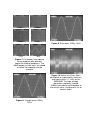
- Square wave response (Fig. 4, 5, 6)
- Capacitive load dependency of
square wave output (Fig. 7)
- Triangle and sine response (Fig. 8,
9)
- Noise and offset (Fig. 10, 11)
Amplitude ( V pp )
140
120
WMA -005
100
80
Figure 1. The 10x probe connected
for monitoring the output signal
60
WMA -005LF
40
The amplifier is capable of amplifying
above 9kHz, and should not be used
for telecommunication as described
in the R&TTE directive 95/5/EC. To
prevent unwanted radiation all leads
should be kept shorter than 30m.
20
0
10
0
10
1
10
2
10
3
10
4
10
5
Frequency (Hz)
Figure 2. Frequency response at
150Vpp output voltage
Noise
The WMA-005 is a low noise
amplifier. The output noise is
typically below 3mVrms. If this is not
good enough, a dedicated version
called the WMA-005LF is available