1
ZeptoProg II™
January 20, 2018
1
https://www.mattairtech.com/
MattairTech LLC
ZeptoProg II™
Table of Contents
Overview........................................................................................................................3
Introduction....................................................................................................................................... 3
Features............................................................................................................................................ 5
QuickStart......................................................................................................................6
Windows Installation....................................................................................................8
Atmel Studio (AVR Studio) / AVRISP mkII driver..............................................................................8
WinAVR............................................................................................................................................ 9
AVRDUDE...................................................................................................................................... 10
BASCOM........................................................................................................................................ 10
ZeptoProg II CDC Driver / Serial Configuration...............................................................................11
Terminal Emulator........................................................................................................................... 11
Linux Installation........................................................................................................12
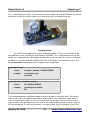
ZeptoProg II Hardware...............................................................................................13
Layout / Header Pins....................................................................................................................... 13
Pin Descriptions.............................................................................................................................. 14
Buttons / LED's............................................................................................................................... 15
AVRISP mkII Compatible Programmer.....................................................................16
Configuration................................................................................................................................... 17
Using Atmel Studio (AVR Studio)....................................................................................................19
Multitool.......................................................................................................................24
Configuration................................................................................................................................... 26
Timer / Pin Setup............................................................................................................................ 28
Input / Output.................................................................................................................................. 29
PWM............................................................................................................................................... 31
Frequency Output........................................................................................................................... 33
Frequency Measurement................................................................................................................ 34
Pattern Generator........................................................................................................................... 35
Logic Analyzer............................................................................................................37
SPI Interface................................................................................................................38
Serial Bridge................................................................................................................43
Firmware Updates.......................................................................................................49
Troubleshooting / FAQ...............................................................................................52
Legal Information........................................................................................................54
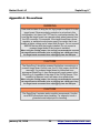
Appendix A: Precautions...........................................................................................56
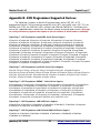
Appendix B: AVR Programmer Supported Devices................................................57
Appendix C: Other MattairTech Products................................................................58
January 20, 2018
2
https://www.mattairtech.com/
MattairTech LLC
ZeptoProg II™
Overview
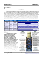
Introduction
The ZeptoProg II™ is an AVRISP mkII compatible USB AVR programmer that supports chips
with the ISP, PDI, or TPI programming interfaces, which includes most megaAVR®, tinyAVR®, and
XMEGA™ series devices. It supports highspeed insystem programming of the AVR flash, EEPROM,
fuses, lock bits, and more using AVR Studio 4 and 5, Atmel Studio 6 and 7, or AVRDUDE. Target
boards operating at 2V to 5.5V are supported. A jumper can be installed to provide 5V through a PTC
fuse to the target board. Additionally, a mutitool mode implements a simple 4channel logic analyzer,
GPIO, PWM, frequency output, frequency measurement, a SPI interface, and configuration, all
accessible using the ZeptoProg II Java application or the command line using a terminal emulator.
Finally, the USB to serial bridge can be used to connect the target to a computer over USB (virtual
COM port) at up to 2Mbps (not recommended for 115.2Kbps or 230.4Kbps).
January 20, 2018
3
https://www.mattairtech.com/
MattairTech LLC
ZeptoProg II™
Java GUI Application
The ZeptoProg II multitool functions can be accessed using a Java GUI application that runs
on Windows and Linux (Mac support included, but untested). This includes the logic analyzer, GPIO,
PWM, frequency output, frequency measurement, and configuration. Additionally, the serial bridge can
be accessed using a very simple terminal emulator. A SPI tab will be added in a future version. The
timer configuration, PWM, and frequency output functions allow entering the target frequency or duty
cycle percentage directly, with autocalculation of the prescaler, top value, PWM resolution, and the
actual frequency (due to quantization error). The frequency measurement displays quantization error
as well. The inputs and frequency measurement can be automatically polled.
January 20, 2018
4
https://www.mattairtech.com/
MattairTech LLC
ZeptoProg II™
Features
●
●
●
●
●
●
●
●
●
●
●
AVRISPmkII compatible AVR Programmer
■ Supports all AVRs with ISP, PDI, or TPI programming interface using standard pinouts
○ Includes megaAVR, tinyAVR, XMEGA, and USB, PWM, and CAN AVRs
■ Optional 5V output via headers to target board, with standard jumper and PTC fuse
■ Up to 8MHz programming speed with optional recovery clock
■ Program flash, EEPROM, fuses, lock bits, and more
■ Works with AVR Studio 4 and 5, Atmel Studio 6 and 7, AVRDUDE, Codevision, and
BASCOM 2.0.6 (use AVRDUDE mode)
Multitool
■ Interface using Java GUI application or command line (via terminal emulator)
■ Logic Analyzer (GUI only)
○ 4 channels, trigger on any combination of pins (or immediately)
○ Fast mode: 1024 samples at 2Msps
○ Auto mode: samples on external clock, up to 60Ksps, up to 10K samples
○ Manual mode: configurable sample rate up to 100Ksps, up to 10K samples
○ Pretrigger buffer (up to 10K samples), posttrigger delay (up to 50K samples)
■ GPIO / PWM / frequency input & output
○ 7 TTL inputs, 9 outputs (5 level shifted)
○ 2 PWM outputs with separate duty cycles
○ 1 frequency output
○ 1 frequency measurement input
○ Pattern generator available in alternate firmware
■ SPI Interface
○ Up to 8MHz clock, ZeptoProg II is master, Modes 03, MSB or LSB
○ 4 chip select outputs (pushpull or opendrain w/ optional pullup)
Serial Bridge
■ Separate serial pins (simultaneous connection of programming cable and serial RX/TX)
■ Up to 2MHz baud rate, synchronous or asynchronous operation
● Not recommended for 115200 or 230400 baud
■ Optional flow control via _CTS_ and _RTS_ pins, 9bit support
Upgradeable firmware / USB bus powered
2 buttons for control / 2 LEDs for status indication
Target board voltage support of 2V to 5.5V via levelshifted pins on two main headers
Reverse polarity protection on Vtgt and GND pins
Overcurrent protection on all output pins via series resistors (signal) and PTC fuse (power)
Measures 5.9cm x 1.8cm x 1.2cm, 1.57mm (0.063”) PCB thickness
Compatible with Windows XP/Vista/7/8/10 (32 and 64 bit)and Linux, with Mac support in
progress.
Uses the AVRISP mkII clone and LUFA library by Dean Camera (http://www.lufalib.org).
January 20, 2018
5
https://www.mattairtech.com/
MattairTech LLC
ZeptoProg II™
QuickStart
Installation
Before using the ZeptoProg II, you must install at least the AVRISP mkII driver and the MattairTech
CDC (virtual COM port) driver. A third DFU driver is available for firmware updates (see Firmware Updates
section). If using Atmel Studio 7, the AVRISPmkII driver must now be downloaded separately (see below).
Extract the archive to any directory, then plug in the ZeptoProg II. Windows will prompt for drivers, so direct
the installer to the new directory. Prior versions of Atmel Studio bundled the AVRISP mkII driver. In these
cases, point the installer to "Program Files/Atmel/AVR Jungo USB" and choose the 32 or 64 bit directory.
Once the AVRISPmkII driver is installed, press the TOOL button. Point the installer to the directory where
you extracted the CDC driver. Remember to rename the file from .txt to .inf if the installer does not see it.
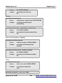
Software
Version
AVRISPmkII
Driver
latest
Tool mode
CDC Driver
latest
CDC driver
https://www.mattairtech.com/software/MattairTech_CDC_Driver_Si
gned.zip
ZeptoProg II
Application
latest
N/A
http://www.mattairtech.com/software/ZeptoProg_II/ZeptoProg_II.jar
or http://www.mattairtech.com/software/ZeptoProg_II/ZeptoProg_II_64.jar
AVR Studio /
Atmel Studio
Driver
URL
AVRISPmkII https://www.mattairtech.com/software/MattairTech_AVRISPmkII_D
driver
river_Signed.zip
http://www.atmel.com/tools/atmelstudio.aspx OR
4.19, 5.x,
Old
6.x, 7.x AVRISPmkII http://www.atmel.com/tools/studioarchive.aspx (for AVR Studio)
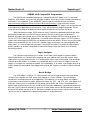
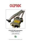
Multitool
The Multitool currently includes a
simple logic analyzer, GPIO, PWM,
frequency generation, frequency
measurement, a SPI interface, and
configuration. The ZeptoProg II Java
application or the command line (via
terminal emulator) can be used to interface
with the multitool. The Java application
runs under Windows and Linux (Mac
support included but untested) and should
be intuitive enough to learn without much
documentation. Features include auto
calculation of the prescaler, top value,
PWM resolution, and the actual frequency
(due to quantization error). The frequency
measurement displays quantization error
as well. The inputs and frequency
measurement can be automatically polled.
January 20, 2018
6
https://www.mattairtech.com/
MattairTech LLC
ZeptoProg II™
AVRISP mkII Compatible Programmer
The AVRISP mkII compatible programmer is compatible with AVR Studio 4.19, 5.x, and Atmel
Studio 6.x. AVR Studio 4.19 can be used with older hardware. All versions can be installed simultaneously.
AVRDUDE is also supported. To use AVRDUDE, you will need to install libusbwin32 available at
http://sourceforge.net/projects/libusbwin32/files/libusbwin32releases/. Choose the latest version,
download, and extract. Then, you must switch the programmer to AVRDUDE mode in the configuration tab
of the ZeptoProg II application (or command line). Then, with the board in programming mode, run the
installfilterwin.exe program included with libusb, which will allow you to install the filter driver.
While in programmer mode, LED B will pulse slowly. Connecting a powered target board to either
programming header will cause the LED to pulse quickly. Use this to verify that the target board is
powered. A jumper can be placed across the 5V and Vtgt pins to output USB 5V to the target board. This
line has a PTC fuse (500mA trip, 200mA hold). Use caution when setting this jumper. DO NOT install the
jumper when connecting to an XMEGA or any board that cannot withstand 5V. Also be sure that the target
board can be powered in this way (ie: if there is a power supply on the target, can it be powered on the
output side?). It is easy to forget that the jumper is installed. If the jumper is installed, the LED will pulse
quickly regardless of whether a target board is connected. Always check the state of this LED before
connecting a board.
Logic Analyzer
The 4channel Logic Analyzer has 3 modes. In fast mode, 1024 samples are taken at 2Msps.
Manual mode allows user selection of the sampling rate up to 100Ksps, with up to 10K samples. Auto
mode makes use of one of the four pins as a sampling clock, either rising or falling edge, at up to 60Ksps
and with up to 10K samples. In all modes, any combination of pins can be used as triggers to start the
capture. If no triggers are selected, the capture starts immediately. In all modes, a posttrigger delay of up
to 50K samples can be enabled. A pretrigger buffer of up to 10K samples is available in manual and auto
modes.
Serial Bridge
The serial bridge is a USB to TTL serial converter that can be used to connect the target board
serial pins to a computer over USB, where it will show up as a virtual COM port. The serial bridge is
configured in the configuration tab of the application. The bridge can run at up to 2Mbps, and supports
asynchronous and synchronous modes, optional flow control via _RTS_ and_CTS_ pins, and support for 5
9 data bits. All pins are levelshifted to the Vtgt voltage. While the RX and TX lines are dedicated, the
optional clock and flow control lines are shared on the PDI header. Additionally, a ground connection must
be made. The ISP cable can provide this ground, or a single jumper wire can be connected to the ground
pin on the PDI header (closest pin to TX). Because the outputs are levelshifted, Vtgt must also be provided
, which can also be supplied via the programming cable or a single jumper wire.
January 20, 2018
7
https://www.mattairtech.com/
MattairTech LLC
ZeptoProg II™
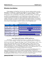
Windows Installation
Before plugging in the ZeptoProg II for the first time, the latest software and drivers must be
downloaded. The ZeptoProg II is supported under Windows XP, Vista (32 and 64 bit), and Windows 7
(32 and 64 bit). There is limited support for Windows 2000. The ZeptoProg II appears as three
different devices to the PC depending on which mode is selected by the buttons. These devices are
the AVRISP mkII compatible programmer, the DFU bootloader for firmware updates, and the USB
CDC device (virtual COM port) which is used for all other modes. Therefore, three drivers are
required. The DFU driver is included with software available on the Atmel website. The CDC driver is
included with Windows, but requires an .inf file available on the MattairTech website. The following
table lists the minimum versions of the required software. If the software provides a driver, is is listed
as well. See the Firmware Updates section for installation of the DFU bootloader driver.
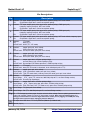
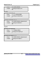
Required Downloads
Software
Version
AVRISPmkII
Driver
latest
Tool mode
CDC Driver
latest
CDC driver
https://www.mattairtech.com/software/MattairTech_CDC_Driver_Si
gned.zip
ZeptoProg II
Application
latest
N/A
http://www.mattairtech.com/software/ZeptoProg_II/ZeptoProg_II.jar
or http://www.mattairtech.com/software/ZeptoProg_II/ZeptoProg_II_64.jar
AVR Studio /
Atmel Studio
Driver
URL
AVRISPmkII https://www.mattairtech.com/software/MattairTech_AVRISPmkII_D
driver
river_Signed.zip
http://www.atmel.com/tools/atmelstudio.aspx OR
4.19, 5.x,
Old
6.x, 7.x AVRISPmkII http://www.atmel.com/tools/studioarchive.aspx (for AVR Studio)
* 64bit version of the application is BETA, use the 32bit version if you have problems
Atmel Studio (AVR Studio) / AVRISP mkII driver
Atmel Studio is a free IDE provided by Atmel that runs on Windows operating systems. It
includes an assembler, debugger, simulator, and an AVR chip programming utility. As of April 2016,
there are four main versions supported, AVR Studio 4.x and 5.x, and Atmel Studio 6.x and 7.x. The 4.x
series is mature and stable, and can run on older hardware, however, it requires the use of the
WinAVR gcc toolchain, which is out of date. It also lacks proper support for newer devices, like the
XMEGA microcontrollers, but is still a good option for older devices. AVR Studio 4.x is also smaller
and less demanding on PC resources. If you choose to use the 4.x series, download version 4.19. You
will also need to download and install WinAVR 20100110 prior to installation.
If installing Atmel Studio 7, the AVRISPmkII driver must now be downloaded separately (see
above). Extract the archive to any directory, then plug in the ZeptoProg II. The AVRISP mkII
compatible AVR programmer will be running. LED A should be lit and LED B should be pulsing on and
off. Windows will prompt for drivers, so direct the installer to the new directory. Prior versions of Atmel
Studio bundled the AVRISP mkII driver. In these cases, point the installer to “Program
January 20, 2018
8
https://www.mattairtech.com/
MattairTech LLC
ZeptoProg II™
Files/Atmel/AVR Jungo USB” and select the appropriate directory (usb32 or usb64). Do not use the
driver in the AVR Tools/usb directory.
If you are having problems communicating with the programmer using Atmel Studio 6.x, please use
the procedure at https://www.olimex.com/forum/index.php?topic=4188.0
WinAVR
WinAVR contains the GNU GCC compiler for C and C++, compiler tools, and libraries
(including AVR Libc). It also includes AVRDUDE for Windows, which is a command line tool for
transferring firmware to AVR microcontrollers. A graphical tool is included with AVR Studio. Download
WinAVR from http://sourceforge.net/projects/winavr/files/WinAVR/20100110/ and install it first. To use
AVRDUDE, you will need to download and install libusbwin32 available at
http://sourceforge.net/projects/libusbwin32/files/libusbwin32releases/. Choose the latest version,
download, and extract. Then, you must switch the programmer to AVRDUDE mode in the
configuration tab of the ZeptoProg II application (or command line). Then, with the board in
programming mode, run the installfilterwin.exe program included with libusb, which will allow you to
install the filter driver. Note that WinAVR is outdated. It is not recommended for newer devices like the
XMEGA series.
January 20, 2018
9
https://www.mattairtech.com/
MattairTech LLC
ZeptoProg II™
AVRDUDE
AVRDUDE can also be installed by itself, but note that AVRDUDE 6.x does not yet support the
ZeptoProg II (it will soon). A working patched version can be found at
http://www.mattairtech.com/software/avrdude_6.0.1_patched_windows.zip.
Thanks to Larry Viesse. For support on Linux 64bit, download
http://www.mattairtech.com/software/avrdude_6.0.1_patched_Linux_64.zip.
For support on other Linux (especially with xhci (USB 3.0)), replace the usb_libusb.c file from 6.0.1
with http://www.mattairtech.com/software/usb_libusb.c.
To use AVRDUDE, you will need to download and install libusbwin32 available at
http://sourceforge.net/projects/libusbwin32/files/libusbwin32releases/. Choose the latest version,
download, and extract. Next, you must switch the programmer to AVRDUDE mode in the configuration
tab of the ZeptoProg II GUI application. Then, with the board in programming mode (pulsing LED), go
to the directory where you installed LibUSB. In the bin directory, you will see three architectures. Click
on the folder that matches your architecture. Note that most 64bit systems will use the amd64 folder,
even if it is Intel (IA64 is a server architecture; Itanium). Now, run the installfilterwin.exe program.
Click “Install a device filter”, then click “Next”. On the next screen, choose the AVRISP mkII then click
“Install”. After installation, close the window with the “X” button (upperright corner).
BASCOM
BASCOM is supported with the programmer in AVRDUDE mode. Thus, the required setup
shown above applies (installation of WinAVR is optional). Details of this process are covered on this
BASCOM AVRISP MKII support page: http://avrhelp.mcselec.com/libusb.htm. They use AVR Studio 4,
but you may install Atmel Studio 5 or higher instead. Follow scenario 1.
January 20, 2018
10
https://www.mattairtech.com/
MattairTech LLC
ZeptoProg II™
ZeptoProg II CDC Driver / Serial Configuration
Next, the ZeptoProg II CDC driver can be installed, which is used by the multitool and serial
bridge. This driver allows the board to appear as a COM port. The driver itself is included with
Windows, but an .inf file is needed to configure it. Download the .inf file from
https://www.mattairtech.com/software/MattairTech_CDC_Driver_Signed.zip. Note that
Windows Vista 64bit, Windows 7 64bit and Windows 8 require the signed driver. Now, plug in the
ZeptoProg II while holding down the TOOL button. This will run the multitool. Only LED B will be lit.
Windows will then prompt you for the ZeptoProg II CDC driver. Point the installer to the directory
where you downloaded the driver and install. Note that you may need to rename the driver in order for
it to show up in the installer. Windows may add the .txt extension to the file after downloading.
Rename it so that it ends with .inf. Ignore any warnings given by the installer (ie: unsigned driver).
Once the driver is loaded, the device will appear as the ZeptoProg II CDC device using a COM port in
the device manager. There is no need to configure serial port parameters. The buad rate, for example,
is ignored. The ZeptoProg II will always communicate with the computer at full speed (up to 2Mbps). If
you experience any buffering problems, for example, a delayed response to user input, then change
both buffer sizes to 1.
Terminal Emulator
Finally, the terminal emulator can be configured. Windows XP includes HyperTerminal, which
has been tested with the ZeptoProg II and will be documented here. There are several other terminal
emulators available freely on the Internet. If you wish to use any of them, it should be no trouble to
adapt the instructions presented here.
Next, start HyperTerminal. Create a new connection. You will refer to this connection again, so
give it an appropriate name (after it is configured, you can copy it to your desktop). Select the
ZeptoProg II COM port (ie: COM4) and continue. It is not necessary to configure the baud rate or any
other serial parameters. Now, click on the connect icon. You should see the ZeptoProg II
prompt. If you do not, just press enter. Note that it may not be possible to switch between modes
using the buttons until a key is pressed.
It is important to always click the disconnect icon before switching to the AVR Programmer.
Then click the connect icon a couple seconds after returning. This is required because changing to the
AVRISPmkII driver unloads the CDC driver, then loads the AVRISPmkII driver. In order for the
terminal to use the same COM port as before, it must be disconnected when returning to the CDC
driver so that it does not assign a new COM port.
January 20, 2018
11
https://www.mattairtech.com/
MattairTech LLC
ZeptoProg II™
Linux Installation
Linux is supported as well. You must download and build the toolchain from the latest script
available at AVR Freaks on the AVR GCC Forum (Script for building AVR GCC sticky at
http://www.avrfreaks.net/index.php?name=PNphpBB2&file=viewtopic&t=42631). All firmware written
for the ZeptoProg II is developed under Linux using this toolchain.
Drivers
TODO (drivers should already be installed)
GCC Toolchain
TODO (see opening paragraph)
AVRDUDE
TODO (ie: avrdude p x128a1 c avrisp2 P usb U flash:w:"myfirmware.hex")
dfuprogrammer
TODO (must use version 0.5.2 (currently available via SVN only) or higher)
Terminal Emulator
TODO (can use minicom, config port (ie: /dev/tty/ACM0), save config, run with minicom o)
●
If you cannot run the java application, be sure to install the 32bit version of Java, which can
coexist with the 64bit version. If running Linux, a 64bit version is available at
http://www.mattairtech.com/software/ZeptoProg_II/ZeptoProg_II_64.jar, but it may not work
with your JRE (it should work with 1.6, but this is now pretty old).
January 20, 2018
12
https://www.mattairtech.com/
MattairTech LLC
ZeptoProg II™
ZeptoProg II Hardware
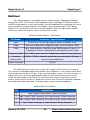
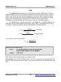
Layout / Header Pins
Header Pinouts (as viewed from above as in diagram, bold is multitool numbering)
Header A
Header B
6
GND
5 / 11
PCK / RTS / RST / out
1/4
MISO / in
2
Vtgt
4 / 10
CTS / in
3/9
TCK / XCK / out
3/5
SCLK / out
4/6
MOSI / out
2
Vtgt
1/8
data / in
5/7
RST / out
6
GND
January 20, 2018
13
https://www.mattairtech.com/
MattairTech LLC
ZeptoProg II™
Pin Descriptions
Pin
Description
0 Multitool: TTL input, output (pushpull or opendrain, optional pullup), NOT level shifted
SPI:
Chip Select 0 (open drain, active low, optional pullup)
1
Multitool: TTL input, output (pushpull or opendrain, optional pullup), PWM (pushpull),
frequency output (pushpull), NOT level shifted
SPI:
Chip Select 1 (open drain, active low, optional pullup)
2
Multitool: TTL input, output (pushpull or opendrain, optional pullup), PWM (pushpull),
frequency output (pushpull), NOT level shifted
SPI:
Chip Select 2 (open drain, active low, optional pullup)
3
Multitool: TTL input, output (pushpull or opendrain, optional pullup), NOT level shifted, frequency input
SPI:
Chip Select 3 (open drain, active low, optional pullup)
4
Multitool:
TTL input
SPI:
MISO (TTL)
AVRISP mkII: MISO (TTL, ISP mode)
5
Multitool:
output (pushpull, level shifted)
SPI:
SCLK (pushpull, level shifted)
AVRISP mkII: SCLK (ISP mode, pushpull, level shifted)
6
Multitool:
output (pushpull, level shifted)
SPI:
MOSI (pushpull, level shifted)
AVRISP mkII: MOSI (ISP mode, pushpull, level shifted)
7
Multitool:
output (opendrain, 47Kohm pullup to Vtgt)
SPI:
unused (always high, 47Kohm pullup to Vtgt)
AVRISP mkII: Reset output (ISP mode, opendrain, 47Kohm pullup to Vtgt)
8
Multitool:
TTL input
AVRISP mkII: data (PDI/TPI mode, bidirectional, level shifted pushpull or TTL)
9
Multitool:
output (pushpull, level shifted)
Serial Bridge: XCK (synchronous mode, pushpull, level shifted)
AVRISP mkII: TCK (TPI mode clock), recovery clock (ISP mode), pushpull, level shifted
10 Multitool:
TTL input
Serial Bridge: _CTS_ input (TTL, active low, 20K50K pullup to 5V, see Serial Bridge section)
AVRISP mkII: unused (high impedance)
11 Multitool:
output (opendrain, 47Kohm pullup to Vtgt)
Serial Bridge: _RTS_ output (active low, opendrain, 47Kohm pullup to Vtgt)
AVRISP mkII: PCK (PDI clock), RST (TPI mode reset), opendrain, 47Kohm pullup to Vtgt
TX Serial Bridge: TX (pushpull, level shifted)
RX Serial Bridge: RX (TTL, 20K50K pullup to 5V, see Serial Bridge section)
Vtgt 2V – 5.5V Voltage input from target. Used to set level shifter voltage. Reverse polarity protected when
jumper not installed. Outputs 5V when 5VVtgt jumper installed. When using the 5V-Vtgt jumper, it is
strongly recommended to connect the target board to the header prior to plugging into a USB port. Keep
the target board connected when unplugging from the USB port.
5V 5V output from USB Vbus, PTC fuse protected (500mA trip, 200mA hold)
GND Ground (2 pins)
January 20, 2018
14
https://www.mattairtech.com/
MattairTech LLC
ZeptoProg II™
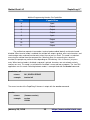
Buttons / LED's
There are four modes of operation which are selected using the buttons. During powerup, the
mode can be selected by holding down the appropriate buttons (if any) when plugging into the USB
port. If no button is held down, the default mode will run, which can be configured as the multitool, the
AVRISP mkII programmer, or the serial bridge. If both buttons are held down, the DFU bootloader will
run. The modes can be changed during runtime as well, except for the DFU Bootloader, which can
only be accessed during powerup. Pressing the PROG button (A) runs the programmer. The AVR is
always reset via the watchdog before running the programmer. If the programmer is already running,
pressing the PROG button will enter the serial bridge. Thus, repeated pressing of the PROG button
toggles between the programmer and serial bridge, which is useful for debugging. Pressing the TOOL
button (B) runs the multitool. If the mutitool is already running, pressing the TOOL button will enter the
serial bridge. The following table lists the button functionality.
Button Functionality During Powerup or Runtime
PROG (A) TOOL (B)
Powerup
Runtime
AVRISP mkII Programmer
Pressed
Not Pressed
AVRISP mkII Programmer
Not Pressed
Pressed
Multitool
Not Pressed Not Pressed
Pressed
Pressed
Serial bridge if already in programmer
Multitool
Serial bridge if already in multitool
Default Mode
N/A
DFU Bootloader
N/A
programmer, multitool, or serial bridge
There are two green LEDs that are used to indicate the mode of operation, communication
activity, and programmer status. The following table lists LED functionality in each mode. When an
LED is used to display communication activity, the default state of the LED is shown on the left. For
example, during serial bridge RX activity, the LED blinks off for a short time then returns to the default
on state.
LED Functionality
Mode
LED A
LED B
AVR Programmer On / Programmer Activity
PWM pulsing
Slow: Target board absent or Vtgt too low
Fast: Target board connected or jumper installed
Multitool
Off / Logic Analyzer Data
On / SPI Activity
Serial bridge
On / RX Activity
On / TX Activity
DFU Bootloader
On
Off
January 20, 2018
15
https://www.mattairtech.com/
MattairTech LLC
ZeptoProg II™
AVRISP mkII Compatible Programmer
The ZeptoProg II AVR Programmer is based on the AVRISP mkII compatible programmer
written by Dean Camera (http://www.fourwalledcubicle.com/). It supports programming of all Atmel
AVR microcontrollers with an ISP, PDI, or TPI programming interface. These include the megaAVR
series (ISP), the tinyAVR series (ISP, TPI), the XMEGA series (PDI), the USB AVRs (ISP), and the
listed CAN and PWM AVRs (see Appendix B for device listing). AVR Studio 4.19 and 5.x, Atmel
Studio 6.x and 7.x, and AVRDUDE are supported. The ZeptoProg II uses the standard header pinouts
for all protocols. The PDI and TPI modes both use programming header A, while ISP mode uses
header B. See hardware section for details on the pinouts.
Programming speeds up to 8MHz are supported in ISP mode. However, current AVRs require
a programming speed less than ¼ of the target clock speed. For 20MHz AVRs, this is 4MHz. For
16MHz, 2MHz is the limit. It is not recommended to operate at exactly ¼ of the target frequency,
especially when programming fuses, as this can cause them to become incorrectly set and possibly
render the AVR useless (unless parallel programming is available). Note that many AVRs come from
the factory with the clock source set to the internal 8MHz oscillator and with the CKDIV8 fuse
programmed, resulting in a clock speed of 1MHz. In these cases, the ISP programming speed should
be set to 125KHz or less until CKDIV8 is unprogrammed and power cycled.
As of firmware version 140126, PDI and TPI programming speeds are now configurable when
using AVRDUDE. By default the PDI/TPI programming speed is 125KHz (250KHz prior to firmware
140126). This speed can be increased up to 250KHz and decreased down to around 17KHz by using
the B option. This option controls the clock period (in ms), so higher numbers mean lower speeds.
For ISP mode, a 1MHz recovery clock can be enabled on the XCK pin (header A). This clock
can be connected to the target clock input. This is useful, for example, to allow resetting of fuses that
were misconfigured to use an external clock when intending to use a crystal or internal oscillator. This
recovery clock should only be used with an ISP programming speed of 125KHz or less.
The ZeptoProg II supports target devices operating at 2V to 5.5V. Outputs from the ZeptoProg
II are levelshifted down to the target voltage. The target device supplies this voltage via the Vtgt input.
This input is reversepolarity protected when the 5VVtgt jumper is not installed. LED B will pulse
slowly when no target board is connected. It will pulse quickly when a powered target board is
connected (~2V or higher). The outputs on the programming headers (A and B) have series resistors
that limit current and control overshoot and ringing.
A jumper can be connected across the 5V and Vtgt pins to output USB 5V to the target via the
programming headers. Use caution when installing this jumper (see Appendix A). DO NOT install this
jumper when connecting to an XMEGA device. LED B will pulse quickly at all times when this jumper
is installed, so it can be used as a reminder that the jumper is installed if it is seen pulsing quickly
without a target board connected. This 5V output is protected from overcurrent conditions by a PTC
fuse. The fuse will trip before reaching 500mA. It will automatically reset when the current drops below
about 200mA.
Always ensure that the ZeptoProg II is powered before connecting the target board. If a
powered target board is connected to an unpowered ZeptoProg II, it will be detected and will enter a
low power state. Note that the orientation of the programming cable connector is marked on the PCB.
January 20, 2018
16
https://www.mattairtech.com/
MattairTech LLC
ZeptoProg II™
Pin 1 is indicated by an asterisk. The connector key points toward the inside of the board. The red wire
will be on the side of the asterisk (there is also a key mark, but it may be difficult to see).
Configuration
The AVRISP mkII programmer has two configuration options. The first is the selection of the
host application, which can be either AVR Studio or AVRDUDE. This is required because these two
modes use a slightly different USB endpoint configuration. If you are using Linux, then this setting will
not matter, as they both work with AVRDUDE for Linux (AVR Studio is not available for Linux). Use
the sysconfig host command to view or change the host configuration.
sysconfig host get
returns:
avrstudio | avrdude | SYNTAX ERROR
example:
sysconfig host get
avrstudio
sysconfig host { avrstudio | avrdude }
returns:
OK | SYNTAX ERROR
example:
sysconfig host avrdude
OK
The second programmer configuration option enables or disables the recovery clock. The recovery
clock can be used in ISP programming mode to output a 1MHz clock signal to the target, which is
useful if incorrect fuse settings result in an unusable AVR. For example, if the fuses were set to an
external clock or to a low frequency crystal, when in fact a high frequency crystal is present, then the
AVR will not operate. The only way to recover is to supply a clock signal, for example, to the XTAL1
January 20, 2018
17
https://www.mattairtech.com/
MattairTech LLC
ZeptoProg II™
pin. It is not usually necessary to remove the crystal, if present, as the clock signal will override it. The
recovery clock is output on pin 9 (programming header A, marked as TCK/XCK). Be sure that the host
is configured for an ISP speed of 125KHz (AVR Studio default) or less. Use the sysconfig recovery
command to view or change the recovery mode setting.
sysconfig recovery get
returns:
disabled | enabled | SYNTAX ERROR
example:
sysconfig recovery get
disabled
sysconfig recovery { disabled | enabled }
returns:
OK | SYNTAX ERROR
example:
sysconfig recovery enabled
OK
January 20, 2018
18
https://www.mattairtech.com/
MattairTech LLC
ZeptoProg II™
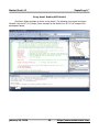
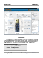
Using Atmel Studio (AVR Studio)
Start Atmel Studio and open or create a new project. The following screenshots from Atmel
Studio 6 show the MTX1S_Simple_Demo template for the MattairTech MTX1S ATxmega128A1
development board.
January 20, 2018
19
https://www.mattairtech.com/
MattairTech LLC
ZeptoProg II™
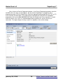
Next, click on the Device Programming button. In the Device Programming window, select the
AVRISP mkII as the tool. If no tool appears, be sure that the ZeptoProg II is plugged in and in
programming mode (LED B will be pulsing). Select the appropriate device and either ISP, PDI, or TPI
as the interface and click Apply. You should now be connected to the AVRISP mkII compatible
programmer with serial number 000200012345. Now click Read next to Device signature. It should
match the device if all is well. It is recommended to always perform this step first to verify the
connection. The target voltage will always read 3.3V, regardless of the actual voltage.
January 20, 2018
20
https://www.mattairtech.com/
MattairTech LLC
ZeptoProg II™
Next, select the Memories page. In the Flash section, a hex file can programmed into the
targets flash memory. Load your hex file, then click Program. The hex file is located in the Debug
folder. You will need to erase the target first if you do not have “Erase Flash before programming”
checked. You should also verify the flash as well.
January 20, 2018
21
https://www.mattairtech.com/
MattairTech LLC
ZeptoProg II™
Next, click on the Fuses tab. It is best to leave the fuse settings alone until you understand
what they do. In particular, if using ISP, do not program RSTDISBL or unprogram SPIEN, as this will
lock you out of the target chip. Do not set the BOD (Brownout detection) voltage to a level above the
target chip voltage, as this will cause the target to be held perpetually in reset. You must also be
careful with the clock settings as well. If you select the wrong clock source, then your target chip will
not operate if the configured clock source is not present. However, the ZeptoProg II provides a
recovery clock which can be used to recover from this situation (see above).
January 20, 2018
22
https://www.mattairtech.com/
MattairTech LLC
ZeptoProg II™
Now you may wish to look at the other pages. Note that any firmware upgrade feature should
not be used. The ZeptoProg II programmer is not an actual AVRISP mkII, it just emulates one, so you
should not attempt to update the ZeptoProg II firmware using Atmel Studio. Any firmware updates will
be posted to the website and loaded using FLIP or dfuprogrammer.
Using AVRDUDE
TODO (ie: avrdude p x128a1 c avrisp2 P usb U flash:w:"myfirmware.hex")
Changing Programming Speed
TODO
Looks like AVRDUDE does indeed send the B setting to the programmer during PDI programming.
The PDI protocol itself does not specify a speed setting mechanism, so I am reusing the mechanism
from ISP programming. With ISP programming over the AVRISP mkII protocol (defined in AVR069),
the speed settings are limited to the following:
> 8000000, 4000000, 2000000, 1000000, 500000, 250000, 125000,
> 96386, 89888, 84211, 79208, 74767, 70797, 67227, 64000,
> 61069, 58395, 55945, 51613, 49690, 47905, 46243, 43244,
> 41885, 39409, 38278, 36200, 34335, 32654, 31129, 29740,
> 28470, 27304, 25724, 24768, 23461, 22285, 21221, 20254,
> 19371, 18562, 17583, 16914, 16097, 15356, 14520, 13914,
> 13224, 12599, 12031, 11511, 10944, 10431, 9963, 9468,
> 9081, 8612, 8239, 7851, 7498, 7137, 6809, 6478, 6178,
> 5879, 5607, 5359, 5093, 4870, 4633, 4418, 4209, 4019,
> 3823, 3645, 3474, 3310, 3161, 3011, 2869, 2734, 2611,
> 2484, 2369, 2257, 2152, 2052, 1956, 1866, 1779, 1695,
> 1615, 1539, 1468, 1398, 1333, 1271, 1212, 1155, 1101,
> 1049, 1000, 953, 909, 866, 826, 787, 750, 715, 682,
> 650, 619, 590, 563, 536, 511, 487, 465, 443, 422,
> 402, 384, 366, 349, 332, 317, 302, 288, 274, 261,
> 249, 238, 226, 216, 206, 196, 187, 178, 170, 162,
> 154, 147, 140, 134, 128, 122, 116, 111, 105, 100,
> 95.4, 90.9, 86.6, 82.6, 78.7, 75.0, 71.5, 68.2,
> 65.0, 61.9, 59.0, 56.3, 53.6, 51.1
These are the numbers you may see in the Atmel Studio programming window when using ISP. I don't
think that PDI programming has a speed setting in Atmel Studio, but I'm not sure. I have not checked
how AVRDUDE translates B values (in microseconds) to the value required by the AVRISP mkII
protocol (an index into the above table; ie: sending a 6 results in a speed of 125KHz).
PDI programming will be limited to the above speeds, but only up to 250KHz. The old fixed speed was
250KHz. The new default speed is 125KHz (same as ISP). I have only been able to get the speed
down to aroung 17KHz (using B 58). Larger values like B 100 did not work.
January 20, 2018
23
https://www.mattairtech.com/
MattairTech LLC
ZeptoProg II™
Multitool
The multitool combines a simple logic analyzer, frequency output, PWM output, frequency
measurement, GPIO, a SPI interface, and configuration for the serial bridge, SPI interface, and the
AVRISP mkII programmer, all accessible through a Java GUI application or the command line using a
terminal emulator or scripting language. The multitool is accessed by pressing the TOOL button
(button B). This section covers most of the multitool capabilities. While the logic analyzer and SPI
interface are a part of the multitool, they are covered in later sections.
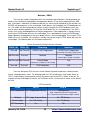
Multitool Pin Mode Features / Specifications
Pin Mode
Features / Specifications
Input
0V0.8V low, 2V5.5V high, optional pullup (2050Kohm to 5V)
Output
pushpull or opendrain (w/optional pullup), current limited to ~20mA
PWM
up to 16bit resolution, up to MHz range PWM frequencies (low res), 2
independent channels, optional phase and frequency correct mode
Frequency Ouput <1Hz 8MHz square wave, two complimentary outputs (same frequency)
Frequency
Measurement
0.333Hz 125KHz, automatic quantization error calculation (GUI only), 1
channel, optional digital filter
Pattern Generator
Pins 03
The multitool primarily involves the use of pins 03, though the SPI interface uses header B.
The 8 signal pins among both programming headers (pin 4 through pin 11) can also be used for GPIO
(currently command line only). As inputs, all pins can read voltages as low as 2V as high. However, as
outputs, only the pins on the two programming headers are level shifted. Because they are level
shifted, the target voltage must be present on at least one of the Vtgt pins (ground must also be
present). All pins that can serve as an output have 249 ohm series resistors for overcurrent protection
and control of overshoot and ringing. The following table summarizes the pin capabilities
Multitool Main Pin Capabilities
Pin
Capabilities
0
Input, Output, Logic Analyzer, Pattern Generator
1
Input, Output, PWM, Frequency Out, Logic Analyzer, Pattern Generator
2
Input, Output, PWM, Frequency Out, Logic Analyzer, Pattern Generator
3
Input, Output, Frequency In, Logic Analyzer, Pattern Generator
January 20, 2018
24
https://www.mattairtech.com/
MattairTech LLC
ZeptoProg II™
Multitool Programming Headers Pin Capabilities
Pin
Capabilities
4
Input
5
Output
6
Output
7
Output
8
Input
9
Output
10
Input
11
Output
The multitool can operate in two modes, terminal mode enabled (default) and terminal mode
disabled. When terminal mode is enabled, the multitool will output a prompt, echo sent characters, and
send carriage return and newline characters when the user presses Enter. This mode is used when
accessing the multitool from the command line. Note that when first connecting via a terminal
emulator, the prompt may not be visible, depending on OS buffering. If this is the case, just press
enter. When terminal mode is disabled, no prompt is printed, characters are not echoed, and only
newlines are sent. This mode is useful when the multitool is accessed from a program. The Java GUI
application uses this mode. Switching between modes is accomplished with the terminal command.
terminal on | off
returns:
OK | SYNTAX ERROR
example:
terminal off
The current version of the ZeptoProg II firmware is output with the version command.
version
returns:
{firmware version}
example:
version
120308
January 20, 2018
25
https://www.mattairtech.com/
MattairTech LLC
ZeptoProg II™
Configuration
All configuration that is stored in the ZeptoProg II EEPROM is accessed through the multitool
using the sysconfig command, which includes serial bridge settings, SPI interface settings, AVRISP
mkII programmer configuration, and the default mode setting. When reading a configuration option,
the get argument is used. When writing, the value to be written is used. The general form is:
sysconfig {configuration option} get
returns:
{value} | SYNTAX ERROR
example:
sysconfig host get
avrstudio
January 20, 2018
26
https://www.mattairtech.com/
MattairTech LLC
ZeptoProg II™
sysconfig {configuration option} {value}
returns:
OK | SYNTAX ERROR | INVALID VALUE
example:
sysconfig host avrdude
OK
Default Mode
When plugging the ZeptoProg II into a USB port without holding either button down, the default
mode will be entered. This can be the multitool (default), the AVRISP mkII programmer, or the serial
bridge. Use the sysconfig default command to view or change the default mode.
sysconfig default get
returns:
programmer | bridge | tool | SYNTAX ERROR
example:
sysconfig default get
tool
sysconfig default { programmer | bridge | tool }
returns:
OK | SYNTAX ERROR
example:
sysconfig default bridge
OK
AVRISP mkII Programmer Configuration
See AVRISP mkII Compatible Programmer section for configuration details.
Serial Bridge Configuration
See Serial Bridge section for configuration details.
SPI Interface Configuration
See SPI Interface section for configuration details.
January 20, 2018
27
https://www.mattairtech.com/
MattairTech LLC
ZeptoProg II™
Timer / Pin Setup
Upon entering the multitool, each pin will be tristated (floating), and must be configured before
use. In general, the setup command is used to associate a pin with a valid function (ie: PWM). In
addition to setting the function of a pin, the setup command sets configuration for the selected
function. For example, a pullup can be enabled for pins setup as an input. Some functions require the
timer to be setup first (ie: PWM). In this case, the setup timer command is used first, then the pin
setup command. The pin or timer setup can subsequently be changed as often as necessary. For
setup arguments that are optional and not specified on the command line, default values are loaded
upon initial setup, but not upon any future invocations (until the pin is reset to a floating state). The
exception to this is with arguments that have only one option (ie: pullup argument of the setup in
command). In this case, specifying it will enable the feature, while omitting it disables the feature
(instead of leaving it unchanged).
setup {pin} in|out|pwm|fi|fo (functionspecific arguments)
returns:
(varies by function)
example:
setup 3 in pullup
{pin}: Required argument indicating the pin number to assign. Can be 011.
in|out|pwm|fi|fo: Required argument specifying the function the pin is to be assigned to. in stands for
input, out stands for output, pwm stands for pulse width modulation, fi stands for frequency input, and
fo stands for frequency output.
(functionspecific arguments): Arguments specific to each function, which may include required
arguments, should be placed here. These arguments are covered in later sections.
If a pin must be changed to a different function (ie: from input to output), then it must be
disassociated with the current function by using the reset command first. Likewise, if the timer is
switched to a different function (ie: PWM to frequency output) and a pin is currently associated with
the function, then the pin(s) must be reset first. The pin is tristated when executing this command.
reset {pin}
returns:
OK | SYNTAX ERROR | INVALID PIN
example:
reset 3
{pin}: Required argument indicating the pin number to unassign. Can be 011.
January 20, 2018
28
https://www.mattairtech.com/
MattairTech LLC
ZeptoProg II™
Timer Setup
The timer must be setup for the PWM, frequency output, and frequency input functions. The
setup timer command configures the timer for the specified function. The prescaler setting (ie: div1)
affects all three functions, while the rest of the settings are used only by the PWM function.
setup timer [off|pwm|fo|fi] [div1|div8|div64|div256|div1024] [fast|phase|freq] [top {16bit value}]
returns:
OK | SYNTAX ERROR | INVALID VALUE | PIN IN USE
example:
setup timer pwm fast top 0x7fff
[off|pwm|fo|fi]: Optional argument that specifies the function the timer will be used for (default off). fo
stands for frequency output and fi for frequency input.
[fast|phase|freq]: Optional argument that specifies what mode the PWM function will run in (default
fast). These correspond to the PWM modes of the underlying AVR microcontroller. Please consult the
Atmega32U2 datasheet for more information. phase stands for phase correct and freq stands for
phase and frequency correct. This setting is ignored when selecting a nonPWM function.
[div1|div8|div64|div256|div1024]: Optional argument that specifies the timer prescaler setting
(default div1). This is the divider of the 16MHz clock frequency. The timer will “tick” at this divided
frequency. Please consult the Atmega32U2 datasheet for more information.
[top {value (16b)}]: Optional argument that specifies the 16bit top value of the timer (default = 0xffff)
used in PWM modes. This is the value the timer will count up to before resetting back to 0 (or
beginning downcounting in certain PWM modes). This setting combined with the prescaler setting
above sets the PWM frequency. Top cannot be below the PWM duty cycle.
Input / Output
The setup in command configures the pin to be used as a TTL compatible input. A pullup
resistor (20K50Kohm to 5V) can optionally be enabled. The in command can then be used to read
the value of the input (0 or 1). Voltages as low as 2V will register as a high.
setup {pin} in [pullup]
returns:
OK | SYNTAX ERROR | PIN IN USE | INVALID PIN | OUT OF MEMORY
example:
setup 1 in pullup
{pin}: Required argument indicating the pin number to assign.
[pullup]: Optional argument that enables the pullup resistor (default disabled).
January 20, 2018
29
https://www.mattairtech.com/
MattairTech LLC
ZeptoProg II™
in {pin}
returns:
0 | 1 | INVALID PIN
example:
in 1
1
{pin}: Required argument indicating the pin number to read.
The setup out command configures the pin to serve as an output. The output can be setup as
pushpull (drive high or low) or as opendrain (drive low, float high). An optional pullup can be enabled
in opendrain mode. The initial state (0 or 1) can optionally be specified. The out command can then
be used to control the output.
setup {pin} out [od] [pullup] [ 0 | 1 ]
returns:
OK | SYNTAX ERROR | PIN IN USE | INVALID PIN | OUT OF MEMORY
example:
setup 3 out
{pin}: Required argument indicating the pin number to assign.
od: Optional argument to configure output as opendrain.
pullup: Optional argument to enable pullup in opendrain mode.
[ 0 | 1 ]: Optional argument specifying the initial state (default high).
out {pin} 0 | 1
returns:
OK | SYNTAX ERROR | INVALID PIN
example:
out 3 1
{pin}: Required argument indicating the pin number to control.
0 | 1: Required argument specifying the output state.
January 20, 2018
30
https://www.mattairtech.com/
MattairTech LLC
ZeptoProg II™
PWM
The setup pwm command configures the specified pin to output a PWM signal. The effect
(normal or invert) of the duty cycle argument can optionally be specified. When normal, the default
output is low, with the high pulse time corresponding to the duty cycle. When inverted, the default
output is high, with the low pulse time corresponding to the duty cycle. Once configured, the pwm
command can be used to change the duty cycle. Pin 1 and pin 2 can be used for PWM
simultaneously, with different duty cycles, but they must share the same PWM frequency.
The PWM frequency is configured during timer setup. Additionally, the mode of operation (fast
PWM, phase correct PWM, and phase and frequency correct PWM) is specified during timer setup
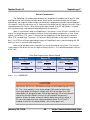
(see above). The following equations can be used to determine the PWM frequency:
F PWM =
F PWM =
16MHz
(fast PWM)
prescaler ∗1TOP
16MHz
(phase/freq PWM)
2∗prescaler∗TOP
The resolution in bits can be found with:
R FPWM=
logTOP1
log2
setup {pin} pwm [normal|invert]
returns:
OK | SYNTAX ERROR | PIN IN USE | INVALID PIN |
INVALID TIMER CONFIG | OUT OF MEMORY
example:
setup 2 pwm
{pin}: Required argument indicating the pin number to assign.
[normal|invert]: When normal, the default output is low, with the high pulse time corresponding to the
duty cycle. When inverted, the default output is high, with the low pulse time corresponding to the duty
cycle.
January 20, 2018
31
https://www.mattairtech.com/
MattairTech LLC
ZeptoProg II™
pwm {pin} {duty cycle (0top)}
returns:
OK | SYNTAX ERROR | INVALID PIN | INVALID VALUE
example:
pwm 2 3000
{pin}: Required argument indicating the pin number to control.
{duty cycle (0top)}: Required argument indicating the duty cycle. The duty cycle as a percent is
Duty Cycle % =
duty cycle
∗ 100%
TOP
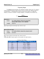
PWM Frequency Ranges
Prescaler
Frequency Range (16b - 2b resolution)
div1
244Hz – 4.00MHz
div8
30.5Hz 500KHz
div64
3.81Hz 62.5KHz
div256
0.954Hz 15.6KHz
div1024
0.238Hz 3.91KHz
January 20, 2018
32
https://www.mattairtech.com/
MattairTech LLC
ZeptoProg II™
Frequency Output
The setup fo command configures the specified pin to output a square wave. Pin 1 and pin 2
can be configured for frequency output, however, they must share the same frequency (but pin 2 is
inverted from pin 1). The fo command can then be used to set the frequency. The higher the
frequency, the lower the resolution in setting the frequency. The frequency can be found using:
F fo =
16MHz
2∗prescaler ∗TOP1
setup {pin} fo
returns:
OK | SYNTAX ERROR | PIN IN USE | INVALID PIN |
INVALID TIMER CONFIG | OUT OF MEMORY
example:
setup 2 fo
{pin}: Required argument indicating the pin number to assign.
fo {pin} {TOP value (16b)}
returns:
OK | SYNTAX ERROR | INVALID PIN | INVALID VALUE
example:
fo 2 0x17ff
{pin}: Required argument indicating the pin number to control.
{TOP value (16b)}: Required argument used to produce the output frequency.
Frequency Output Ranges
Prescaler Setting
Frequency Range (TOP 65535 - 0)
div1
122Hz – 8.00MHz
div8
15.3Hz – 1.00MHz
div64
1.91Hz – 125KHz
div256
0.477Hz – 31.3KHz
div1024
0.119Hz – 7.81KHz
January 20, 2018
33
https://www.mattairtech.com/
MattairTech LLC
ZeptoProg II™
Frequency Measurement
The setup fi command is used to configure the specified pin (3 only) as an input to measure
frequencies. Optionally, a simple digital filter may be enabled. See ATmega32U2 datasheet for details.
The fi command can then be used to measure the frequency. The frequency will be calculated and
displayed in Hertz. If no signal is present when the command is executed, the command will timeout
with a TIMEOUT error message after a few seconds. If the frequency is too high, a CAPTURE TOO
FAST error occurs. The next higher frequency range can then be selected, if available. Note that if the
frequency of interest exists within multiple ranges, use the highest range in order to maximize
resolution. If the frequency is too low, then a CAPTURE OVERFLOW error occurs.
setup {pin} fi [filter]
returns:
OK | SYNTAX ERROR | PIN IN USE | INVALID PIN |
INVALID TIMER CONFIG | OUT OF MEMORY
example:
setup 3 fi
{pin}: Required argument indicating the pin number to assign.
[filter]: See ATmega32U2 datasheet for details.
fi {pin}
returns:
or
{frequency (16b)}Hz
SYNTAX ERROR | INVALID PIN | TIMEOUT | CAPTURE OVERFLOW |
CAPTURE TOO FAST
example:
fi 3
7426.284Hz
{pin}: Required argument indicating the pin number to use.
Frequency Input Ranges
Prescaler Setting
Frequency Range
div1
244Hz 125KHz
div8
30.5Hz 15.6KHz
div64
3.81Hz 1.95KHz
div256
0.954Hz 488Hz
div1024
0.238Hz 122Hz
January 20, 2018
34
https://www.mattairtech.com/
MattairTech LLC
ZeptoProg II™
Pattern Generator
The pattern generator can be used to output arbitrary digital patterns on any combination of
pins 03. These patterns are stored in EEPROM. The pattern generator is a new feature and it does
not currently fit into the firmware due to limited FLASH space. To use it, you will have to install
different firmware available at
http://www.mattairtech.com/software/ZeptoProg_II/ZeptoProg_II_PG.hex. In order to make room for
the pattern generator, the SPI commands in the multitool are not present. The pattern generator
currently can only be accessed from the commandline. It is implemented with 4 commands (2 new
commands and 2 modifications to existing commands):
setup pattern
This command is used to read/write patterns from/to EEPROM. One pin at a time can be read/written.
setup pattern {pin} [get] (you can omit get)
returns the pattern, for example:
ZeptoProg II> setup pattern 0
8 steps
repeat 255
H 10 L 8 H 6 L 4 H 2 L 4 H 6 L 8
or
pattern disabled
setup pattern {pin} [set] off (you can omit set)
clears the pattern
setup pattern {pin} [set] repeat {0255} (h|l {165535} )+ (you can omit set)
returns OK|SYNTAX ERROR|INVALID VALUE|PIN IN USE|INVALID PIN|OUT OF
MEMORY
Repeat specifies how many times the pattern repeats after the initial run. The special value of 255
means repeat forever. Repeat must be specified and it must be positioned as above. The actual
pattern follows the repeat value. Each step in the pattern is specified with an actiondelay pair. The
action can be either l or h. The delay must be at least 1 and up to 65535. They delay specifies the
number of timebase ticks. More actiondelay pairs can be added, separated with a space. Each of the
4 pins is configured one at a time. Each of the 4 patterns can be up to 83 steps. Note that the terminal
buffer size of 512 bytes may limit using all 83 steps. If you cannot type any more characters, the buffer
is full. Each pattern is written into EEPROM, so they will be saved even after power is removed.
To setup a pattern as shown in the above example:
setup pattern 0 repeat 255 h 10 l 8 h 6 l 4 h 2 l 4 h 6 l 8
If the pattern generator timebase (setup timer commend) is set to 1ms, then the above pattern will set
the pin high for 10ms, low for 8ms, etc.
January 20, 2018
35
https://www.mattairtech.com/
MattairTech LLC
ZeptoProg II™
setup timer
setup timer [off|pwm|fo|fi|pattern] [fast|phase|freq] [div1|div8|div64|div256|div1024]
[top {value (16b)}]
returns OK|SYNTAX ERROR|INVALID VALUE|PIN IN USE
The timer is used to set the timebase, so the existing setup timer command is used. All delays used in
the pattern are a multiple of this timebase. The timebase can be as low as 100us and as high as
4.19s. Using combinations of clock divider and top value that result in a timebase of less than 100us
will return an error. I have more optimization work left, so avoid using a timebase under 250us for now.
To set the timebase to 1ms:
setup timer pattern div1 top 16000
This must be setup prior to using the pattern generator. This can be changed at any time, even while a
pattern is running.
setup pin
setup {pin} pattern [1|0](initial state)
returns OK|SYNTAX ERROR|PIN IN USE|INVALID PIN|INVALID TIMER CONFIG|OUT OF
MEMORY
This associates a pin with the pattern generator. The timer must be setup for pattern generation first.
The initial state will be output immediately.
pattern
pattern on|off (0|1|2|3 [repeat {0255}])+
returns OK|SYNTAX ERROR|INVALID PIN|INVALID VALUE|PIN IN USE
repeat=0 is no repeat, repeat=255 is indefinite repeat
Start or stop pattern generation. Do after associating pins with the pattern generator. Multiple pins can
be specified. The repeat value can be used optionally to override the value stored in EEPROM. When
specifying multiple pins, they will be started/stopped simultaneously. When starting, the pattern will
begin on the next timebase tick. For example, if the timebase is 1ms, the start of the pattern(s) will be
delayed by up to 1ms. If the pattern has a repeat value (from EEPROM or the override value), the
pattern will repeat the specified number of times. When a pattern stops, either manually with this
command or by reaching the end of the pattern, the pin will be left at its current state (ie: last pattern
state). Example:
pattern on 0 1 repeat 24 4
This starts patterns 0 and 4 using EEPROM repeat values and starts pattern 1 with repeat value of 24.
January 20, 2018
36
https://www.mattairtech.com/
MattairTech LLC
ZeptoProg II™
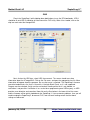
Logic Analyzer
TODO: This section is not yet documented. It should be fairly intuitive. Unorganized notes follow.
If you cannot run the java application, be sure to install the 32bit version of Java (or download the
64bit version of the GUI).
When using auto mode, you must select what channel the sampling clock is on.
In rare cases, especially when using the pretrigger buffer, you may receive a buffer overflow error. If this
happens, try again. Fast mode can never have a buffer overflow, but is limited to 1024 samples.
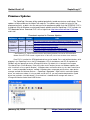
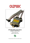
You may simultaneously use functions from the GPIO/PWM/Freq tab and the logic analyzer (see screenshot,
which shows PWM generated from the ZeptoProg II). It does not matter if the pins are inputs or outputs, the logic
analyzer can always read them. Note that Manual mode requires use of the timer.
There is a zoom tool. Click and drag the section you want to see closer. Click the magnifying glass icon to return
to unzoomed. You can save the capture as an image or print it.
Pretrigger buffer data (if used) is displayed on the negative side of the Xaxis.
January 20, 2018
37
https://www.mattairtech.com/
MattairTech LLC
ZeptoProg II™
SPI Interface
The SPI interface is useful for testing SPI devices or for controlling SPI devices via PC
software. With terminal mode enabled, data to be sent is placed on the command line in either ASCII
or hex. With Terminal Mode disabled, data is transferred in binary. The ZeptoProg II should be
powered before the target board. Gnd and Vtgt must be connected to the target board. There are up to
4 chip select outputs on pins 03. These are opendrain and activelow. An optional pullup (20K
50Kohm to 5V) can be enabled by configuring the pin as an input with pullup, or by configuring the pin
as an opendrain output with pullup (see Multitool section above).
SPI Configuration
There are several SPI configuration options, which are stored in EEPROM. These options are
accessed using the sysconfig spi command. The speed can be set from 125KHz up to 8MHz. Note
that while the maximum speed over the ZeptoProg II USB connection is 2Mbps, a higher SPI speed
may be selected, which can improve performance due to overhead. The SPI mode (03) and data
order (MSB, LSB) must be set to match the SPI slave device. The optional dummy byte can be used
to mask data sent from the slave. Since SPI devices always send and receive data in both directions
simultaneously, this can be useful for ignoring return data from the slave (MISO) when it has no
significance. Any byte from the slave that matches the dummy byte value will not be sent over USB.
SPI Configuration Options
Configuration Option
Possible Values
Speed
8MHz, 4MHz, 2MHz, 1MHz, 500KHz, 250KHz, 125KHz
SPI Mode
0, 1, 2, 3
Data Order
MSB, LSB
Dummy Byte
Disabled, Enabled
Dummy Byte Value
0x00 0xFF
Speed
sysconfig spi speed get
returns:
8000000 | 4000000 | 2000000 | 1000000 | 500000 | 250000 | 125000 |
SYNTAX ERROR
example:
sysconfig spi speed get
2000000
January 20, 2018
38
https://www.mattairtech.com/
MattairTech LLC
ZeptoProg II™
sysconfig spi speed { 8000000 | 4000000 | 2000000 | 1000000 | 500000 | 250000 | 125000 }
returns:
OK | SYNTAX ERROR | INVALID VALUE
example:
sysconfig spi speed 4000000
OK
Mode
sysconfig spi mode get
returns:
0 | 1 | 2 | 3 | SYNTAX ERROR
example:
sysconfig spi mode get
0
sysconfig spi mode { 0 | 1 | 2 | 3 }
returns:
OK | SYNTAX ERROR | INVALID VALUE
example:
sysconfig spi mode 3
OK
Dataorder
sysconfig spi dataorder get
returns:
msb | lsb | SYNTAX ERROR
example:
sysconfig spi dataorder get
msb
sysconfig spi dataorder { msb | lsb }
returns:
OK | SYNTAX ERROR | INVALID VALUE
example:
sysconfig spi dataorder lsb
OK
Dummy Byte
sysconfig spi dummy get
returns:
disabled | enabled | SYNTAX ERROR
example:
sysconfig spi dummy get
disabled
January 20, 2018
39
https://www.mattairtech.com/
MattairTech LLC
ZeptoProg II™
sysconfig spi dummy { disabled | enabled }
returns:
OK | SYNTAX ERROR
example:
sysconfig spi dummy enabled
OK
Dummy Byte Value
sysconfig spi dummyvalue get
returns:
{ 0x00 0xFF } | SYNTAX ERROR
example:
sysconfig spi dummyvalue get
0xff
sysconfig spi dummyvalue { 0x00 0xFF }
returns:
OK | SYNTAX ERROR | INVALID VALUE
example:
sysconfig spi dummyvalue 0x00
OK
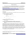
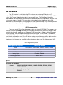
SPI Commands
There are 3 commands. They are t (transfer), w (write), and r (read). There are 2 versions of
each command. The version used depends on whether Terminal Mode is enabled or not. If enabled,
an additional argument is available (hex) and data to be sent is entered directly on the command line.
If not enabled, hex is not available, and the length of data must be specified. Any data to write is sent
only after the command is entered (newline) and only if the return value is OK. If OK, the ZeptoProg II
will then read length bytes from USB.
The chip select line to use (03) is a required argument. Normally, the ZeptoProg II holds the
specified chip select low only for the duration of the command. The optional argument hold keeps the
chip select line low between commands until either hold is omitted, another chip select line is
specified, or multitool mode is exited. This can be useful in terminal mode if the length of data to send
exceeds the remaining command line buffer space, or if you wish to mix hexadecimal and ASCII.
The optional hex argument is useful to enter binary data when in Terminal Mode. If specified,
separate values can then be listed separated by whitespace. Values starting with “0x” are interpreted
as hexadecimal, but values can be entered in decimal as well. When hex is not specified, all
characters are interpreted as ASCII.
example:
example:
w 0 Hello World!
t hex 0 0xc1 0x00 0x03 4 5
January 20, 2018
40
https://www.mattairtech.com/
MattairTech LLC
ZeptoProg II™
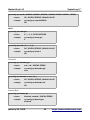
SPI Transfer
Terminal Mode On:
t [hold] [hex] 0|1|2|3 <TX data (up to remaining line buffer size)>
returns:
OK | SYNTAX ERROR | INVALID PIN | INVALID HEX
action:
If OK, TX data from the command line is sent over SPI. The length of data is
determined automatically from the command line. For each TX byte, an RX
byte is read from SPI and sent over USB. If the dummy byte is used, all bytes
from SPI that match the dummy byte value will be discarded.
Terminal Mode Off:
t [hold] 0|1|2|3 {length(16b)}
returns:
OK | SYNTAX ERROR | INVALID PIN
action:
If OK, length bytes of TX data are read from USB and sent over SPI. For each
TX byte, an RX byte is read from SPI and sent over USB. If the dummy byte is
used, all bytes from SPI that match the dummy byte value will be discarded.
SPI Write
Terminal Mode On:
w [hold] [hex] 0|1|2|3 <tx data (up to remaining line buffer size)>
returns:
OK | SYNTAX ERROR | INVALID PIN | INVALID HEX
action:
If OK, TX data from the command line is sent over SPI. The length of data is
determined automatically from the command line.
Terminal Mode Off:
w [hold] 0|1|2|3 {length(16b)}
returns:
OK | SYNTAX ERROR | INVALID PIN
action:
If OK, length bytes of TX data are read from USB and sent over SPI.
January 20, 2018
41
https://www.mattairtech.com/
MattairTech LLC
ZeptoProg II™
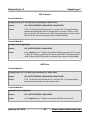
SPI Read
Terminal Mode On:
r [hold] [hex] 0|1|2|3 {length(16b)}
returns:
OK | SYNTAX ERROR | INVALID PIN
action:
If OK, length bytes of RX data are read from SPI and sent over USB. If the
dummy byte is used, all bytes from SPI that match the dummy byte value will
be discarded.
Terminal Mode Off:
r [hold] 0|1|2|3 {length(16b)}
returns:
OK | SYNTAX ERROR | INVALID PIN
action:
If OK, length bytes of RX data are read from SPI and sent over USB. If the
dummy byte is used, all bytes from SPI that match the dummy byte value will
be discarded.
Example Session
This example demonstrates communication with a SPI SRAM chip (Microchip 23K256) in
Terminal Mode using chip select 0 with an 8MHz clock. The hold feature is used to mix commands in
hexadecimal (and decimal) with data in ASCII.
SPI >
OK
FF 00
SPI >
OK
07 FF
SPI >
OK
FF 41
SPI >
OK
t hex 0 5 0
t hex 0 1 0x41
t hex 0 5 0
w hold hex 0 2 0 0
SPI > w 0 Hello World!
OK
SPI > w hold hex 0 3 0 0
OK
SPI > r 0 12
OK
Hello World!
January 20, 2018
42
https://www.mattairtech.com/
MattairTech LLC
ZeptoProg II™
Serial Bridge
The serial bridge can connect the target MCU (or other device) to a host application (ie:
terminal emulator) over USB. On the host side, the ZeptoProg II will appear as a virtual COM port.
Unlike the multitool, there is no terminal mode or commands. The ZeptoProg II simply relays bytes
between the host and target. Speeds up to 2Mbps* are supported on separate RX and TX pins. The
optional synchronous mode clock and flow control pins can be taken from programming header A.
* Not recommended for 115.2Kbps or 230.4Kbps. At these speeds and higher, choose a baud rate that the
8MHz cpu clock can be divided down to (ie: 125Kbps).
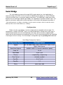
Configuration
Before using the serial bridge, it must be configured to be compatible with the target. This
configuration is stored in EEPROM. There is no need to duplicate the settings on the host side, as
communication between the host and ZeptoProg II will always be the maximum supported USB
speed, and the other parameters are ignored by the host. Only the connection between the ZeptoProg
II and target use these settings. The serial bridge is configured using the sysconfig serial command.
Serial Bridge Configuration Options
Configuration Option
Possible Values
Speed
2M, 1M, 500K, 250K, 125K, 76.8K, 57.6K, 38.4K, 19.2K,
9600, 2400, manual
Baud Rate Register
0x0000 0x0FFF (if manual selected as speed)
Clock 2X
1X, 2X
Clock Mode
async, sync
Polarity
samplefalling, samplerising
Flow Control
disabled, enabled
Data Bits
5, 6, 7, 8, 9
Stop Bits
1, 2
Parity
none, even, odd
January 20, 2018
43
https://www.mattairtech.com/
MattairTech LLC
ZeptoProg II™
Speed
sysconfig serial speed get
returns:
2400 | 9600 | 19200 | 38400 | 57600 | 76800 | 125000 | 250000 | 500000 |
1000000 | 2000000 | manual | SYNTAX ERROR
example:
sysconfig serial speed get
57600
sysconfig serial speed { 2400 | 9600 | 19200 | 38400 | 57600 | 76800 | 125000 | 250000 |
500000 | 1000000 | 2000000 | manual }
returns:
OK | SYNTAX ERROR | INVALID VALUE
January 20, 2018
44
https://www.mattairtech.com/
MattairTech LLC
example:
ZeptoProg II™
sysconfig serial speed manual
OK
Baud Rate Register (manual speed setting)
sysconfig serial baudregister get
returns:
{ 0x0000 – 0x0FFF } | SYNTAX ERROR
example:
sysconfig serial baudregister get
0x340
sysconfig serial baudregister { 0x0000 – 0x0FFF | 0 – 4095 }
returns:
OK | SYNTAX ERROR | INVALID VALUE
example:
sysconfig serial baudregister 832
OK
2X Clock mode (manual speed, asynchronous mode only)
sysconfig serial clock2x get
returns:
disabled | enabled | SYNTAX ERROR
example:
sysconfig serial clock2x get
disabled
sysconfig serial clock2x { disabled | enabled }
returns:
OK | SYNTAX ERROR
example:
sysconfig serial clock2x enabled
OK
Serial Mode
sysconfig serial mode get
returns:
async | sync | SYNTAX ERROR
example:
sysconfig serial mode get
async
sysconfig serial mode { async | sync }
January 20, 2018
45
https://www.mattairtech.com/
MattairTech LLC
ZeptoProg II™
returns:
OK | SYNTAX ERROR
example:
sysconfig serial mode sync
OK
Polarity
sysconfig serial polarity get
returns:
samplefalling | samplerising | SYNTAX ERROR
example:
sysconfig serial polarity get
samplefalling
sysconfig serial polarity { samplefalling | samplerising }
returns:
OK | SYNTAX ERROR
example:
sysconfig serial polarity samplerising
OK
Flow Control (hardware, CTS/RTS)
sysconfig serial flowcontrol get
returns:
disabled | enabled | SYNTAX ERROR
example:
sysconfig serial flowcontrol get
disabled
sysconfig serial flowcontrol { disabled | enabled }
returns:
OK | SYNTAX ERROR
example:
sysconfig serial flowcontrol enabled
OK
Parity
sysconfig serial parity get
returns:
none | even | odd | SYNTAX ERROR
example:
sysconfig serial parity get
none
sysconfig serial parity { none | even | odd }
January 20, 2018
46
https://www.mattairtech.com/
MattairTech LLC
ZeptoProg II™
returns:
OK | SYNTAX ERROR
example:
sysconfig serial parity even
OK
Data Bits
sysconfig serial databits get
returns:
{ 5 – 9 } | SYNTAX ERROR
example:
sysconfig serial databits get
8
sysconfig serial databits { 5 – 9 }
returns:
OK | SYNTAX ERROR | INVALID VALUE
example:
sysconfig serial databits 9
OK
Stop Bits
sysconfig serial stopbits get
returns:
1 | 2 | SYNTAX ERROR
example:
sysconfig serial stopbits get
1
sysconfig serial stopbits { 1 | 2 }
returns:
OK | SYNTAX ERROR | INVALID VALUE
example:
sysconfig serial stopbits 2
OK
January 20, 2018
47
https://www.mattairtech.com/
MattairTech LLC
ZeptoProg II™
Serial Connections
The ZeptoProg II should be powered before the target board. In addition to RX and TX, Gnd
and Vtgt must be connected to the target board, which can be connected through the ISP cable.
Alternatively, two single pin cables can be connected to the programming header Vtgt and Gnd pins.
On header A, Gnd is the closest pin to TX. Vtgt can also be taken from the Vtgt pin next to RX. Vtgt is
required because the TX line is level shifted to the target voltage. If the 5VVtgt jumper is installed,
then connecting Vtgt is not required (target board must also be at 5V).
When in synchronous mode, the ZeptoProg II is the master, so the XCK pin is enabled as an
output. The target board must enable its clock pin as an input and be configured as a slave. If flow
control is used, when CTS is low, TX activity from the ZeptoProg II to the target occurs normally.
When CTS is brought high, TX pauses. This prevents buffer overflows on the target if it becomes
busy. The RTS line will likewise be brought low by the ZeptoProg II when it cannot keep up with RX
data (ie: if there is upstream USB congestion).
When using 9bit data frames, two bytes are sent or received for every frame. The first byte
simply contains the 9th bit, thus the first byte will always be 0 or 1. The second byte contains the rest
of the 8 bits.
Baud Rate Register Value (Manual Speed)
Async 1X
f osc
−1
16∗BAUD
UBRR=
f osc
16∗UBRR1
BAUD=
UBRR=
BAUD=
where
Async 2X
Synchronous
f osc
−1
8∗BAUD
UBRR=
f osc
8∗UBRR1
BAUD=
f osc
−1
2∗BAUD
f osc
2∗UBRR1
f osc =16000000
CAUTION
Note that the RX line has a 20K50Kohm pullup resistor enabled that pulls RX to
5V. This is true regardless of the target voltage. AVRs and most other chips
have clamp diodes that keep the voltage within 0.5V of the target Vcc. AVR
clamp diodes are designed to allow 1mA to flow indefinitely. Since the pullup will
limit current to under 150uA in all cases, the 5V pullup will not present a
problem. A future firmware version will add the ability to turn off this pullup. In
this case, the target must have a pullup enabled/installed. The CTS pin, if
enabled, also has this 5V pullup enabled, so the same applies to it.
January 20, 2018
48
https://www.mattairtech.com/
MattairTech LLC
ZeptoProg II™
Firmware Updates
The ZeptoProg II firmware will be updated periodically to add new features and fix bugs. These
updates will be available on the MattairTech website. The updates may include just a hex file (for
programming flash), or both a hex file and eep file (for programming both flash and EEPROM). FLIP is
a graphical utility for Windows used to load firmware updates onto the ZeptoProg II. FLIP includes the
DFU bootloader driver. Download FLIP 3.4.2 or higher from http://www.atmel.com/tools/FLIP.aspx
and install.
Downloads required for Firmware Updates
Software Version
ZeptoProg II
Firmware*
latest
FLIP
3.4.2 +
Signed DFU
Driver*
latest
Driver
URL
N/A
http://www.mattairtech.com/software/ZeptoProg_II/ZeptoProg_II.hex OR
http://www.mattairtech.com/software/ZeptoProg_II/ZeptoProg_II_PG.hex
DFU driver http://www.atmel.com/tools/FLIP.aspx
DFU driver
http://www.avrfreaks.net/index.php?module=Freaks
%20Academy&func=viewItem&item_type=project&item_id=2196
* The ZeptoProg_II_PG.hex firmware contains the pattern generator, but not the SPI commands.
* Newer versions of FLIP include a signed driver. In this case, do not use the driver from avrfreaks.
Once FLIP is installed, the DFU bootloader driver can be loaded. Press and hold both buttons while
plugging in the ZeptoProg II to run the DFU bootloader. LED A should be on and LED B should be off.
Windows will then prompt you for the ATmega32U2 driver. By default, this is located in the Program
Files/Atmel/Flip 3.4.2/usb directory. Point the installer to this location (do not use Windows update, then
click 'Install from a list or specific location'). If Windows does not find the driver, try the “don't search/have
disk → show incompatible hardware” method. If Windows does not prompt you for drivers, open device
manager and look for Unknown Devices → ZeptoProg II Bootloader. Rightclick this and select Update
driver, hen continue as above. If using an older version of FLIP, you may need to download the signed
driver from avrfreaks (see table above). Once the driver is loaded, device manager will show an
ATmega32U2 device under Atmel USB Devices.
January 20, 2018
49
https://www.mattairtech.com/
MattairTech LLC
ZeptoProg II™
FLIP
Plug in the ZeptoProg II while holding down both buttons to run the DFU bootloader. LED A
should be on and LED B should be off. Now launch the FLIP utility. When it has loaded, click on the
chip icon and select the Atmega32U2.
Next, click on the USB icon, select USB, then connect. The screen should now show
information about the ATmega32U2. Click on the File menu, and open the appropriate hex file. More
information will appear about the program. Be sure that erase is checked. The ZeptoProg II firmware
cannot be loaded unless the flash is erased first. Uncheck Blank Check, as it is not supported.
Program must be checked. Verify must be unchecked. Reading of the flash is not allowed, so
verification is not possible. Verification is less useful when programming over USB anyway, as USB
provides error detection and correction. Now click on the Run button in the lowerleft of the screen,
and the firmware will be quickly loaded onto the ZeptoProg II. If you encounter problems, then you will
need to unplug the ZeptoProg II, disconnect FLIP, and start over making certain that the above
settings are observed.
January 20, 2018
50
https://www.mattairtech.com/
MattairTech LLC
ZeptoProg II™
You may also need to program the EEPROM. If so, click on Select EEPROM at the bottom.
Then, click on the File menu and open the appropriate eep file. You will have to change the file filter to
allow you to see the eep file. Note that eep files are just hex files but with the eep extension instead of
hex. More information will appear about the file when selected. Both Program and Verify should be
checked. Click run to program the EEPROM.
dfuprogrammer (Linux)
A chip erase must be performed first. The flash cannot be read.
dfuprogrammer atmega32u2 erase
dfuprogrammer atmega32u2 flasheeprom ZeptoProg_II_120306.eep (if applicable)
dfuprogrammer atmega32u2 flash suppressvalidation ZeptoProg_II_120306.hex
January 20, 2018
51
https://www.mattairtech.com/
MattairTech LLC
ZeptoProg II™
Troubleshooting / FAQ
●
If Atmel Studio wants you to upgrade the firmware, first check that you are not in AVRDUDE
programming mode, which can trigger this warning. If you are in AVR/Atmel Studio mode and
still get the message, please check the website for firmware updates or email
[email protected] if you are already using the latest version.
●
If you cannot run the java application, be sure to install the 32bit version of Java, which can
coexist with the 64bit version. A beta 64bit version is available at
http://www.mattairtech.com/software/ZeptoProg_II/ZeptoProg_II_64.jar.
●
Updating the firmware with recent versions of FLIP (ie: 3.4.7) may fail. If so, try using the
batchisp command line tool included with FLIP:
C:\Program Files\Atmel\Flip 3.4.7\bin>batchisp -device ATMEGA32U2 -hardware USB
-operation erase F loadbuffer "C:\ZeptoProg_II.hex" program start reset 0
●
If BASCOM or AVRDUDE do not work, be sure to put the programmer into AVRDUDE mode.
●
Prior to releasing the signed driver on January 28, 2015, Windows 8 users needed to disable
driver signing to use Tool mode (terminal emulator or Java app.).
●
Atmel Studio (AVR Studio) reports 3.3V when the board in fact is operating at 5V.
Ignore this. The ZeptoProg II cannot measure the voltage of the target (but it can detect the
presence of a voltage on Vtgt as low as 2V). Voltage reporting is informational only, it does not
affect programming.
●
AVRDUDE 6.x does not yet support the ZeptoProg II. A working patched version
can be found at http://www.mattairtech.com/software/avrdude_6.0.1_patched_windows.zip.
Thanks to Larry Viesse. For support on Linux 64bit, download
http://www.mattairtech.com/software/avrdude_6.0.1_patched_Linux_64.zip.
For support on other Linux (especially with xhci (USB 3.0)), replace the usb_libusb.c file from
6.0.1 with http://www.mattairtech.com/software/usb_libusb.c.
●
If you are having problems communicating with the programmer using Atmel Studio 6.x,
download the Zadig USB driver manager at http://zadig.akeo.ie/.
Under options, List All Devices. The AVRISP mkII should show up in the list. Replace the
current driver with libusbwin32 (v1.2.6.0), which comes embedded with Zadig.
Alternatively, please use the procedure at https://www.olimex.com/forum/index.php?
topic=4188.0
●
Prior to firmware version 150815, if the PDI/TPI connection to the target board was bad, then
Atmel Studio would experience connection issues to the programmer itself for some time after
the initial failure. Restarting AS would not immediately restore communications (however, after
several attempts / time waited, it will come back). Firmware 150815 solves this by lowering the
programmer<>target timeout (AS ignored the timeout response after a certain period of time).
January 20, 2018
52
https://www.mattairtech.com/
MattairTech LLC
ZeptoProg II™
●
If you are having problems communicating with the programmer using Atmel Studio 7.x, please
ensure that you are using the new AVRISPmkII driver, which now must be downloaded
separately (see installation). Prior versions of Atmel Studio included this driver.
●
If you are having problems writing the FLASH of the Tiny4/5/9/10 (timeout using Atmel Studio),
please update the firmware to at least 160808.
Support Information
Please check the MattairTech website (http://www.MattairTech.com/) for firmware and software
updates. Email me if you have any feature requests, suggestions, or if you have found a bug. If you
need support, please contact me (email is best). You can also find support information at the
MattairTech website. A support forum is planned. Support for AVRs in general can be found at
AVRfreaks (http://www.avrfreaks.net/). There, I monitor the forums section as the user physicist.
Justin Mattair
MattairTech LLC
PO Box 1079
Heppner, OR 97836 USA
541-626-1531
[email protected]
http://www.mattairtech.com/
Acknowledgments
Thanks to Dean Camera (http://www.fourwalledcubicle.com/) for his excellent LUFA library,
AVRISPmkII clone, and DFU bootloader, all of which are used in the ZeptoProg II firmware. Thanks to
the members of AVRfreaks (http://www.avrfreaks.net/) for their support. Finally, thanks to Atmel for
creating a great product, the AVR microcontroller.
January 20, 2018
53
https://www.mattairtech.com/
MattairTech LLC
ZeptoProg II™
Legal Information
Copyright Notices
Copyright
Copyright
Copyright
Copyright
Copyright
Copyright
©
©
©
©
©
©
2009-2012, Justin Mattair (http://www.mattairtech.com/)
2009-2012, Dean Camera (http://www.lufa-lib.org)
2010, ChaN (http://elm-chan.org/)
2003-2011, Atmel Corporation (http://www.atmel.com/)
2005 Pascal S. de Kloe (http://quies.net/java/math/plot/)
1997-2007 Trent Jarvi [email protected] and others (http://rxtx.qbang.org/)
Software Disclaimer
The author(s) disclaim all warranties with regard to this software, including all implied
warranties of merchantability and fitness. In no event shall the author(s) be liable for any
special, indirect or consequential damages or any damages whatsoever resulting from loss of
use, data or profits, whether in an action of contract, negligence or other tortious action,
arising out of or in connection with the use or performance of this software.
Hardware Disclaimer
This development tool is intended for use for FURTHER ENGINEERING OR DEVELOPMENT PURPOSES
ONLY. It does not comply with some or any technical or legal requirements that are
applicable to finished products, including, without limitation, directives regarding
electromagnetic compatibility, recycling (WEEE), FCC, CE, or UL (except as may be otherwise
noted). MattairTech LLC supplied this development product AS IS, without any warranties,
with all faults, at the buyer's and further users' sole risk. The user assumes all
responsibility and liability for proper and safe handling of the goods. Further, the user
indemnifies MattairTech LLC from all claims arising from the handling or use of the goods.
Due to the open construction of the product, it is the user's responsibility to take any and
all appropriate precautions with regard to electrostatic discharge and any other technical
or legal concerns.
The product described in this document is subject to continuous development and
improvements. All particulars of the product and its use contained in this document are
given by MattairTech LLC in good faith. However all warranties implied or expressed
including but not limited to implied warranties of merchantability or fitness for particular
purpose are excluded.
This document is intended only to assist the reader in the use of the product. MattairTech
LLC shall not be liable for any loss or damage arising from the use of any information in
this document or any error or omission in such information or any incorrect use of the
product.
Trademarks
ZeptoProg II™ is a trademark of MattairTech LLC.
AVR® is a registered trademark of Atmel Corporation.
All other trademarks are the property of their respective owners.
January 20, 2018
54
https://www.mattairtech.com/
MattairTech LLC
ZeptoProg II™
Licenses
LUFA USB Library
Copyright 2012
Dean Camera (dean [at] fourwalledcubicle [dot] com)
Permission to use, copy, modify, distribute, and sell this
software and its documentation for any purpose is hereby granted
without fee, provided that the above copyright notice appear in
all copies and that both that the copyright notice and this
permission notice and warranty disclaimer appear in supporting
documentation, and that the name of the author not be used in
advertising or publicity pertaining to distribution of the
software without specific, written prior permission.
The author disclaim all warranties with regard to this
software, including all implied warranties of merchantability
and fitness. In no event shall the author be liable for any
special, indirect or consequential damages or any damages
whatsoever resulting from loss of use, data or profits, whether
in an action of contract, negligence or other tortious action,
arising out of or in connection with the use or performance of
this software.
QN Plot
Copyright (c) 2005 Pascal S. de Kloe. All rights reserved.
Redistribution and use in source and binary forms, with or without modification,
are permitted provided that the following conditions are met:
1. Redistributions of source code must retain the above copyright notice, this
list of conditions and the following disclaimer.
2. Redistributions in binary form must reproduce the above copyright notice,
this list of conditions and the following disclaimer in the documentation
and/or other materials provided with the distribution.
3. The name of the author may not be used to endorse or promote products derived
from this software without specific prior written permission.
THIS SOFTWARE IS PROVIDED BY THE AUTHOR ``AS IS'' AND ANY EXPRESS OR IMPLIED
WARRANTIES, INCLUDING, BUT NOT LIMITED TO, THE IMPLIED WARRANTIES OF
MERCHANTABILITY AND FITNESS FOR A PARTICULAR PURPOSE ARE DISCLAIMED. IN NO
EVENT SHALL THE AUTHOR BE LIABLE FOR ANY DIRECT, INDIRECT, INCIDENTAL, SPECIAL,
EXEMPLARY, OR CONSEQUENTIAL DAMAGES (INCLUDING, BUT NOT LIMITED TO, PROCUREMENT
OF SUBSTITUTE GOODS OR SERVICES; LOSS OF USE, DATA, OR PROFITS; OR BUSINESS
INTERRUPTION) HOWEVER CAUSED AND ON ANY THEORY OF LIABILITY, WHETHER IN
CONTRACT, STRICT LIABILITY, OR TORT (INCLUDING NEGLIGENCE OR OTHERWISE) ARISING
IN ANY WAY OUT OF THE USE OF THIS SOFTWARE, EVEN IF ADVISED OF THE POSSIBILITY
OF SUCH DAMAGE.
RXTX Serial Library
RXTX License v 2.1 - LGPL v 2.1 + Linking Over Controlled Interface.
RXTX is a native interface to serial ports in java.
Copyright 1997-2007 by Trent Jarvi [email protected] and others who actually wrote it.
See individual source files for more information.
A copy of the LGPL v 2.1 may be found at
http://www.gnu.org/licenses/old-licenses/lgpl-2.1.html
64-bit RXTX binary builds provided as a courtesy of Mfizz Inc. (http://mfizz.com/).
Please see http://mfizz.com/oss/rxtx-for-java for more information.
January 20, 2018
55
https://www.mattairtech.com/
MattairTech LLC
ZeptoProg II™
Appendix A: Precautions
WARNING
Care must be taken if using the 5V-Vtgt jumper to output 5V to the
target board. Reverse polarity protection is not active in this
configuration, but there is a PTC fuse for overload protection. Be
sure that the target board can operate safely when powered from
the ISP connector. For example, if the target board has a linear
regulator or switched mode power supply, be certain that it can
sustain a higher voltage on its output than its input. Do not connect
XMEGA devices with the jumper installed. Do not connect a
powered target board if the jumper is installed.
When using the 5V-Vtgt jumper, it is strongly recommended to connect
the target board to the header prior to plugging into a USB port. Keep
the target board connected when unplugging from the USB port.
CAUTION
The ZeptoProg II should be powered first before connecting to a
powered target board (in this case, the 5V-Vtgt jumper should be
removed). If a powered target board is connected to an
unpowered ZeptoProg II, then the target will supply power to the
ZeptoProg II, regardless of the state of the 5V-Vtgt jumper. This
condition is detected, and it will enter a low power state.
When using the 5V-Vtgt jumper, it is strongly recommended to connect
the target board to the header prior to plugging into a USB port. Keep
the target board connected when unplugging from the USB port.
CAUTION
The ZeptoProg II contains static sensitive components. Use the
usual ESD procedures when handling. For example, touch a
grounded metal object prior to handling.
January 20, 2018
56
https://www.mattairtech.com/
MattairTech LLC
ZeptoProg II™
Appendix B: AVR Programmer Supported Devices
The ZeptoProg II supports all Atmel AVR microcontrollers with an ISP, PDI, or TPI
programming interface. These include the megaAVR series (ISP), the tinyAVR series (ISP, TPI), the
XMEGA series (PDI), the USB AVRs (ISP), and the listed CAN and PWM AVRs. The following lists
most of the supported models. Add to these the different voltage and speed grade variants. New chips
are usually automatically supported with updates to the host software (ie: Atmel Studio or AVRDUDE).
ZeptoProg II™ AVR Programmer megaAVR® Series Device Support
ATmega128, ATmega1280, ATmega1281, ATmega1284, ATmega1284P, ATmega128A, ATmega16,
ATmega162, ATmega164A, ATmega164P, ATmega164PA, ATmega165, ATmega165A, ATmega165P,
ATmega168, ATmega168A, ATmega168P, ATmega168PA, ATmega169, ATmega169A, ATmega169P,
ATmega169PA, ATmega16A, ATmega16HVB, ATmega2560, ATmega2560, ATmega2561, ATmega32,
ATmega324A, ATmega324P, ATmega324PA, ATmega325, ATmega3250, ATmega3250A, ATmega3250P,
ATmega325A, ATmega325P, ATmega328, ATmega328P, ATmega329, ATmega3290, ATmega3290A,
ATmega3290P, ATmega329A, ATmega329P, ATmega329PA, ATmega32A, ATmega32C1, ATmega32HVB,
ATmega32M1, ATmega48, ATmega48A, ATmega48P, ATmega48PA, ATmega64, ATmega640, ATmega644,
ATmega644A, ATmega644P, ATmega644PA, ATmega645, ATmega6450, ATmega6450A, ATmega6450P,
ATmega645A, ATmega645P, ATmega649, ATmega6490, ATmega6490A, ATmega6490P, ATmega649A,
ATmega649P, ATmega64A, ATmega64HVE, ATmega8, ATmega8515, ATmega8535, ATmega88, ATmega88A,
ATmega88P, ATmega88PA, ATmega8A, ATmega8HVD
ZeptoProg II™ AVR Programmer tinyAVR® Series Device Support
ATtiny10, ATtiny12, ATtiny13, ATtiny13A, ATtiny15, ATtiny1634, ATtiny167, ATtiny20, ATtiny2313,
ATtiny2313A, ATtiny24, ATtiny24A, ATtiny25, ATtiny26, ATtiny261, ATtiny261A, ATtiny4, ATtiny40, ATtiny4313,
ATtiny43U, ATtiny44, ATtiny441, ATtiny44A, ATtiny45, ATtiny461, ATtiny461A, ATtiny48, ATtiny5, ATtiny84,
ATtiny841, ATtiny85, ATtiny861, ATtiny861A, ATtiny88, ATtiny9
ZeptoProg II™ AVR Programmer XMEGA™ Series Device Support
ATxmega16A4U, ATxmega32A4U, ATxmega64A3U, ATxmega128A3U, ATxmega192A3U, ATxmega256A3U,
ATxmega256A3BU, ATxmega64B3, ATxmega128B3, ATxmega64B1, ATxmega128B1, ATxmega16A4,
ATxmega32A4, ATxmega64A4U, ATxmega128A4U, ATxmega64A3, ATxmega128A3, ATxmega192A3,
ATxmega256A3, ATxmega256A3B, ATxmega64A1, ATxmega128A1, ATxmega16D4, ATxmega32D4,
ATxmega64D4, ATxmega128D4, ATxmega64D3, ATxmega128D3, ATxmega192D3, ATxmega256D3,
ATxmega128A1U, ATxmega128A4, ATxmega192A1, ATxmega256A1, ATxmega384A1, ATxmega64A4,
ATxmega8e5, ATxmega16e5, ATxmega32e5, XMEGA B series, XMEGA C series
ZeptoProg II™ AVR Programmer USB AVR Device Support
AT90USB1286, AT90USB1287, AT90USB162, AT90USB646, AT90USB647, AT90USB82, ATmega16U2,
ATmega16U4, ATmega32U2, ATmega32U4, ATmega8U2
ZeptoProg II™ AVR Programmer CAN AVR and PWM AVR Device Support
AT90CAN128, AT90CAN32, AT90CAN64, AT90PWM2, AT90PWM216, AT90PWM2B, AT90PWM3,
AT90PWM316, AT90PWM3B
January 20, 2018
57
https://www.mattairtech.com/
MattairTech LLC
ZeptoProg II™
Appendix C: Other MattairTech Products
MTDBX4 USB AVR XMEGA board
●
●
●
●
●
●
●
●
ATxmega128A4U USB XMEGA AVR
128KB FLASH, 8KB SRAM, 2KB EEPROM
3.3V LDO regulator (low quiescent current)
16MHz and 32.768KHz crystals
LED, boot jumper, PDI header
Reset button, mounting holes
USB DFU bootloader preinstalled
MTD21E USB ARM Cortex M0+ board
●
●
●
●
●
●
●
●
●
ATSAMD21E17A or ATSAMD21E18A (32pin)
128KB/256KB FLASH, 16KB/32KB SRAM
Onboard 3.3V, 250mA LDO regulator (2uA quiescent)
16MHz and 32.768KHz crystals
USB connector (power by USB or external up to 16V)
Blue LED, 10pin Cortex header, 2 buttons, I2C pullups
USB CDC or MSD Bootloader (no programmer required)
Arduino 1.6.5+ support (core and bootloader)
MTDBX3 USB AVR XMEGA board
●
●
●
●
●
●
●
●
●
XMEGA A3U, A3BU, C3, and D3 (64pin)
32KB 384KB FLASH, 4KB – 32KB SRAM
3.3V 250mA regulator (2uA quiescent current)
Optional 5V 500mA regulator (23uA quiescent current)
Optional autodirection sensing level shifter
16MHz and 32.768KHz crystals, optional coin cell holder
LED, boot jumper, PDI header, button, TWI pullups
USB DFU bootloader preinstalled (except D variant)
MTD11 USB ARM Cortex M0+ board
●
●
●
●
●
●
●
●
●
January 20, 2018
ATSAMD11D14AM (24pin)
16KB FLASH, 4KB SRAM
Onboard 3.3V, 250mA LDO regulator (2uA quiescent)
16MHz and 32.768KHz crystals
USB connector (power by USB or external up to 16V)
Blue LED, 10pin Cortex header, button, I2C pullups
USB CDC Bootloader (no programmer required)
Arduino 1.6.5+ support (core and bootloader)
58
https://www.mattairtech.com/