1
Manual
MTDBU2
October 29, 2015
1
http://www.mattairtech.com/
MT-DB-U2
Manual
Table of Contents
Overview........................................................................................................................3
Introduction....................................................................................................................................... 3
MTDBU2 Features.......................................................................................................................... 3
ATmega32U2 Features..................................................................................................................... 4
MTDBU2 Hardware.....................................................................................................6
Layout / Header Pins......................................................................................................................... 6
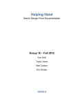
Solder Jumpers................................................................................................................................. 7
Pin Descriptions................................................................................................................................ 8
PWM Filters...................................................................................................................................... 9
Clock Source..................................................................................................................................... 9
HWB Jumper / RESET button / LED.................................................................................................9
ISP Header..................................................................................................................................... 10
Power Configuration..................................................................................................11
USB Bus Powered 5V.................................................................................................................. 11
USB Bus Powered – 3.3V............................................................................................................... 11
Externally Powered – 4.0V to 5.5V..................................................................................................12
Externally Powered – 3.0V to 3.6V..................................................................................................12
USB Shield...................................................................................................................................... 12
Arduino Compatibility................................................................................................13
Features.......................................................................................................................................... 13
Pin Mapping.................................................................................................................................... 13
Installation....................................................................................................................................... 14
Using Arduino.................................................................................................................................. 14
Using Libraries................................................................................................................................ 15
USB Serial interface........................................................................................................................ 15
CDC Bootloader (Arduino/AVRDUDE)......................................................................18
CDC Serial Driver............................................................................................................................ 18
CDC Bootloader.............................................................................................................................. 18
DFU Bootloader (FLIP/dfuprogrammer)..................................................................20
FLIP................................................................................................................................................ 21
dfuprogrammer.............................................................................................................................. 23
Running Bitlash Demo...............................................................................................24
Schematic....................................................................................................................26
Troubleshooting / FAQ...............................................................................................27
Support Information...................................................................................................27
Acknowledgments......................................................................................................27
Legal.............................................................................................................................28
Appendix A: Precautions...........................................................................................29
Appendix B: Other MattairTech Products................................................................30
October 29, 2015
2
http://www.mattairtech.com/
MT-DB-U2
Manual
Overview
Introduction
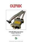
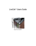
The MTDBU2 is a development board for the Atmel ATmega32U2 USB microcontroller. The
Atmega32U2 contains 32 KB of flash, 1 KB of RAM, 1 KB EEPROM, 22 programmable IO pins, and a
USB device controller. The board has 32 pins in a dual inline configuration with 100 mil pin spacing
and 600 mil row spacing which allows for easy mounting on a breadboard. It includes a mini USB
connector, status LED, 16MHz crystal, reset button, HWB boot jumper, 3 PWM filters, and ISP header
pads. A bootloader comes preinstalled which allows programming of the chip over USB without an
external programmer. The ISP header can be used with an external programmer for insystem
programming. This header can be reconfigured to allow the MTDBU2 itself to be an ISP
programmer, or to be used as a SPI master or slave. The board can be powered at 5V via USB, at
3.3V via the ATmega32U2 internal regulator and USB, or it can be powered externally (3V – 3.6V or
4.0V – 5.5V). All programmable IO pins are routed to headers, including those used by onboard
hardware. The chip can be clocked externally, and the board is compatible with HV programming. The
USB connections are also routed to header pins, which allows for panelmount USB connectors. The
PCB is highquality with ENIG (goldplated) finish, red soldermask, and white screenprinting showing
the pinout. It measures approximately 1.7” x 0.8” (42mm x 20mm) and is 0.062” (1.6mm) thick.
MTDBU2 Features
●
ATmega32U2 USB microcontroller
● 32KB FLASH, 1KB SRAM, 1KB EEPROM
● USB device controller, Serial USART, and SPI communications
● 2 timers with 5 PWM channels
●
Arduino compatible
CDC (Arduino/AVRDUDE) or DFU (FLIP) bootloader preinstalled
Bitlash preinstalled (Arduino command shell)
●
●
●
●
●
●
●
●
●
●
●
●
●
●
●
●
ISP header pads (program chip using external programmer)
16MHz crystal
Green Status LED
3 RC PWM filters on each output compare pin of 16bit timer 1 (can be disconnected)
Reset button
Bootloader selection jumper
Mini USB connector
Can be powered via USB at 5V (Vbus) or 3.3V (ATmega32U2 internal regulator)
Can be powered externally at 3V to 3.6V or 4V to 5.5V
All programmable IO pins routed to headers (including those used by onboard hardware)
USB pins routed to header pins (for panelmount USB connector)
Highquality PCB with goldplated finish and red soldermask
DIL32 board, standard 0.1" pin spacing. Can be mounted on a breadboard
Measures approx. 1.7” x 0.8” (42mm x 20mm) and 0.062” (1.6mm) thick.
October 29, 2015
3
http://www.mattairtech.com/
MT-DB-U2
Manual
ATmega32U2 Features
●
●
●
●
●
●
●
●
High Performance, Low Power AVR® 8Bit Microcontroller
Advanced RISC Architecture
125 Powerful Instructions – Most Single Clock Cycle
32 x 8 General Purpose Working Registers
Fully Static Operation
Up to 16 MIPS Throughput at 16 Mhz
Nonvolatile Program and Data Memories
32K Bytes of InSystem SelfProgrammable Flash
1024 Bytes EEPROM
1024 Bytes Internal SRAM
Write/Erase Cycles: 10,000 Flash/ 100,000 EEPROM
Data retention: 20 years at 85°C/ 100 years at 25°C(1)
Optional Boot Code Section with Independent Lock Bits
InSystem Programming by onchip Boot Program
True ReadWhileWrite Operation
Programming Lock for Software Security
USB 2.0 Fullspeed Device with Interrupt on Transfer Completion
Complies fully with Universal Serial Bus Specification REV 2.0
48 MHz PLL for Fullspeed Bus Operation: 12 Mbit/s data rate
Fully independant 176 bytes USB DPRAM for endpoint memory
Endpoint 0 for Control Transfers: from 8 up to 64bytes
4 Programmable Endpoints:
IN or Out Directions
Bulk, Interrupt and IsochronousTransfers
Programmable maximum packet size from 8 to 64 bytes
Programmable single or double buffer
Suspend/Resume Interrupts
Microcontroller reset on USB Bus Reset without detach
USB Bus Disconnection on Microcontroller Request
Peripheral Features
One 8bit Timer/Counters with Separate Prescaler and Compare
(two 8bit PWM channels)
One 16bit Timer/Counter with Prescaler, Compare and Capture
(three 8bit PWM channels)
USART with SPI master mode and hardware flow control (RTS/CTS)
Master/Slave SPI Serial Interface
Programmable Watchdog Timer with Separate Onchip Oscillator
Onchip Analog Comparator
Interrupt and Wakeup on Pin Change
On Chip Debug Interface (debugWIRE)
Special Microcontroller Features
PowerOn Reset and Programmable Brownout Detection
Internal Calibrated Oscillator
External and Internal Interrupt Sources
5 Sleep Modes: Idle, Powersave, Powerdown, Stby., and Ext. Stby.
I/O and Packages
22 Programmable I/O Lines
October 29, 2015
4
http://www.mattairtech.com/
MT-DB-U2
●
●
●
Manual
QFN32 (5x5mm) / TQFP32 packages
Operating Voltages
2.7 – 5.5V
Operating temperature
Industrial (40°C to +85°C)
Maximum Frequency
8 MHz at 2.7V Industrial range
16 MHz at 4.5V Industrial range
October 29, 2015
5
http://www.mattairtech.com/
MT-DB-U2
Manual
MTDBU2 Hardware
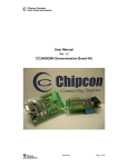
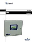
Layout / Header Pins
October 29, 2015
6
http://www.mattairtech.com/
MT-DB-U2
Manual
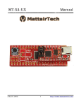
Solder Jumpers
October 29, 2015
7
http://www.mattairtech.com/
MT-DB-U2
Manual
Pin Descriptions
Pin
Description
Gnd
Ground
5V, Vbus
5V output from USB Vbus. Vbus pin and 5V pin are tied together.
Vcc
Voltage input pin. Use solder jumper J8 to configure. This pin is connected
to the Vcc and AVcc pins on the microcontroller, as well as the ISP header
and reset pullup. See Power Configuration Section.
3.3V
3.3V output from the microcontroller internal 3.3V regulator. This pin is
connected to Ucap on the microcontroller.
X2 (C0)
This pin can be connected to the XTAL2 pin of the microcontroller using
jumper J7. This is useful if pin C0 is used as GPIO (if external clock is
used). This pin is disconnected by default (onboard crystal is used).
X1
This pin can be connected to the XTAL1 pin of the microcontroller using
jumper J7. This is useful if an external clock is used. This is also useful for
HV programming or recovery from incorrectly set fuses. This pin is
disconnected by default (onboard crystal is used).
C2
GPIO pin (Port C) Consult datasheet for functionality.
D0 D7
GPIO pins (Port D) Consult datasheet for functionality.
D0 / LED
The green status LED is connected to this pin when solder jumper J2 is
set. The LED is connected to ground through a 240 ohm resistor. The user
application is free to use this LED. Drive the pin high to turn on the LED.
D7 / HWB
This pin is connected to the bootloader jumper (HWB). The jumper is
connected to ground through a 240 ohm resistor. The pin is sampled after
all reset sources, including powerup. If the pin is low (HWB jumper
installed), then the bootloader is run. If the pin is high (HWB jumper
removed), then the user application is run. This pin functions as a normal
GPIO pin at all other times. The 240 ohm resistor provides shortcircuit
protection in case the pin is used as an output and the jumper is installed.
RST
Connects to reset pin of microcontroller as well as the reset button. A 10K
pullup resistor and 100nF capacitor are connected to this pin. If jumper J1
is set to ISP In, then RST is also connected to pin 5 of the ISP header.
B0 B6
GPIO pins (Port B) Consult datasheet for functionality.
B7
PWM filter C output (OC.1C) or pin B7, depending on jumper
configuration.
C4, C7
GPIO pins (Port C) Consult datasheet for functionality.
C5
PWM filter B output (OC.1B) or pin C5, depending on jumper
configuration.
C6
PWM filter A output (OC.1A) or pin C6, depending on jumper
configuration.
October 29, 2015
8
http://www.mattairtech.com/
MT-DB-U2
Manual
D+, D
USB data pins. Can be used for panelmount connectors.
PWM Filters
There are three PWM filters, which can be used to smooth out a PWM square wave
into an analog voltage (with some ripple). The outputs of these filters can be connected to
header pins C6, C5, and B7 using solder jumpers J4, J5, and J3 respectively (factory default).
The filters consist of a 1K resistor and 100nF capacitor. The cutoff frequency is:
f 3db =1/2 RC =1/2 1K∗100nF=1/2 0.0001=1600Hz
This is a firstorder lowpass filter that can output levels from 0V to Vcc. All three filter
inputs are connected to the 16bit timer 1 output compare pins ( OC.1A, OC.1B, and OC.1C).
The filter inputs are always connected to the microcontroller. Therefore, if the solder jumpers
are configured to connect the microcontroller pins directly to the header pins, there will be
some loading on the pin (1K resistor in series with a 100nF capacitor to ground).
Clock Source
By default, a 16 MHz crystal is installed and connected to the XTAL pins of the
Atmega32U2. This 16 Mhz clock must be divided by 2 in software if the Vcc voltage is less
than 4.5V. If an external clock is is used, solder jumper J6 can be switched to connect the
microcontroller pin directly to header pin rather than the onboard crystal. An external clock
signal can then be applied to pin X1 (XTAL1). This will also free up microcontroller pin C0
(XTAL2), which can be configured in the microcontroller as a GPIO pin and routed to header
pin X2 by switching solder jumper J7.
HWB Jumper / RESET button / LED
The HWB Jumper is used to select either the bootloader or user application. The pin is
sampled after reset or powerup. Note that the hardware HWB function of the ATmega32U2 is
disabled. That is, the HWBE fuse is disabled. The bootloader startup code is always run after reset or
powerup (BOOTRST fuse is set). The code samples the state of the HWB pin. If the pin is low, the
bootloader continues to run. If the pin is high, the user application is run. The green LED will pulse on
and off using a continuously changing PWM period when the DFU bootloader is running. If the
preinstalled demo program is running, it will be lit when USB is connected. Otherwise, the state of the
LED is controlled by the user application. The bootloader always runs at 8 MHz, which is compatible
with lower voltages. The user may set the cpu speed to 16MHz in software, if running at 5V.
October 29, 2015
9
http://www.mattairtech.com/
MT-DB-U2
Manual
Jumper
No
Yes
Mode
User Program
Bootloader Program
Driver
CDC (COM port) (optional)
CDC Serial/DFU Bootloader
It is not necessary to remove and replace the jumper when switching between the bootloader
and the user application. The jumper can be left on. After FLASH programming, the CDC bootloader
will automatically jump to the application. If using the DFU bootloader, then you can command FLIP
or dfuprogrammer to jump to the application. Then, when running the application, the reset button can
be pressed to reenter the bootloader. This is useful when writing and debugging firmware. When the
firmware is complete, the jumper can be removed so that future resets will always run the application.
The pins associated with the LED, jumper, and reset button are all routed to header pins. The
LED can be disconnected by unsoldering jumper J2. The jumper is connected to pin D7 on one side
and to ground through a 240 ohm resistor on the other side. There is a 10K pullup on the reset line.
ISP Header
The ISP header is configured by default to allow ISP programming using an external
programmer. That is, RESET is routed to pin 5. Pin 1 is marked on the board (it is the pin closest to
the chip). The ISP header can be reconfigured so that pin PB0 (SS) is connected to pin 5 rather than
RESET. This can be done by switching solder jumper J1. This allows the MTDBU2 to be used as an
AVRISPmkII programmer itself, using Dean Camera's AVRISPmkII software available at
http://www.fourwalledcubicle.com/. A precompiled hex file will be made available at
http://www.mattairtech.com/ on the MTDBU2 product page. Note that when using the ISP header in
this way, Vcc and ground are output to the target board. Therefore, the target board should not be
powered itself. You should also verify that it is safe to power the target board through the ISP
connector. Another use for the ISP header configured with SS on pin 5 is to make use of SPI, either as
a master or slave. SPI can also be used on the normal DIL headers. When using the ISP header, you
may need to remove the HWB jumper to allow the ISP connector to fit.
October 29, 2015
10
http://www.mattairtech.com/
MT-DB-U2
Manual
Power Configuration
The MTDBU2 can be powered in a variety of ways by utilizing solder jumper J8 located on
the bottom of the board. By default, the board is configured to be powered via USB, with Vcc at 5V,
and the microcontroller internal 3.3V regulator enabled and powering only the USB pads. The
microcontroller clock is configured at boot to run at 8MHz. The following lists some of the
configurations possible. Code may have to be recompiled when switching configurations (ie: to
change cpu clock speed and/or internal regulator power).
Power Configuration
Jumper J8
USB bus powered – 5V Vcc (default)
USB Bus powered – 3.3V Vcc
Externally powered – 4.0 to 5.5V Vcc
Externally powered – 3.0 to 3.6V Vcc
3.3V Vcc = 5V = UVcc Vcc
3.3V = Vcc 5V = UVcc Vcc
3.3V Vcc 5V UVcc = Vcc
3.3V = Vcc 5V UVcc = Vcc
Regulator Max CPU
Enable
Enable
Enable
Disable
16 MHz
8 MHz
16 MHz
8 MHz
WARNING
Care must be taken when configuring the solder jumpers.
It is possible to cause permanent damage to the device or the
power supply by improperly setting the jumpers.
Do not change any jumpers while the unit is powered.
When using the microcontrollers internal regulator to power itself,
be sure not to exceed the regulator maximum current output.
USB Bus Powered 5V
By default, the MTDBU2 is configured for 5V from the USB connector (Vbus). In this
configuration, solder jumper J8 is set such that Vcc and UVcc are connected to Vbus (5V). The AVR
internal 3.3V regulator must be enabled (default setting). This will supply 3.3V to the USB pads and
3.3V header pin.
USB Bus Powered – 3.3V
The internal 3.3V regulator can be used to supply the AVR itself with 3.3V. In this configuration,
solder jumper J8 is set such that Vcc is connected to 3.3V and UVcc is connected to Vbus (5V). The
AVR internal 3.3V regulator must be enabled (default setting). This will supply 3.3V to the AVR itself,
October 29, 2015
11
http://www.mattairtech.com/
MT-DB-U2
Manual
the USB pads, and the 3.3V header pin. Take care not to exceed the datasheet maximum current
output of the internal regulator. Note that at 3.3V, the AVR should be set to run at 8MHz or less. This
can be done in software using the prescaler.
Externally Powered – 4.0V to 5.5V
In this configuration, solder jumper J8 is set such that UVcc is connected to Vcc. Vcc is then
supplied externally with 4.0V to 5.5V on the Vcc header pin. The 5V pin still outputs 5V when the USB
cable is plugged in. The AVR internal 3.3V regulator must be enabled (default setting). This will supply
3.3V to the USB pads and 3.3V header pin. Note that when using a voltage less than 4.5V, the AVR
should be set to run at 8MHz or less. This can be done in software using the prescaler.
Externally Powered – 3.0V to 3.6V
In this configuration, solder jumper J8 is set such that both UVcc and 3.3V are connected to
Vcc. Vcc is then supplied externally with 3.0V to 3.6V on the Vcc header pin. The internal 3.3V
regulator must be disabled in software. Note that the regulator is always enabled after reset or
powerup, and is on when the bootloader is running. It is the responsibility of the user application to
disable the regulator. The 5V pin still outputs 5V when the USB cable is plugged in. In this
configuration, the AVR should be set to run at 8MHz or less. This can be done in software using the
prescaler.
USB Shield
Jumper J9 can be soldered to connect the USB shield to ground. The USB specification calls
for the USB shield to be connected to ground on the host side only. However, it may be desired to
ground this on the device side. An 0603 SMT component may be soldered on the solder jumper pads
as well.
October 29, 2015
12
http://www.mattairtech.com/
MT-DB-U2
Manual
Arduino Compatibility
Features
●
●
●
●
●
●
●
●
●
●
●
●
●
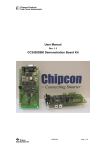
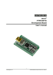
Arduino core and libraries ported to MattairTech USB boards
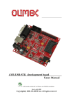
MTDBU2: 21 digital, 4 PWM, 8 INT, 13 PCINT, SPI, USART1, 32KB FLASH, 1KB SRAM,
1KB EEPROM
USB Serial interface replaces USART0
Hardware maximum speed of 8Mbps (U4/U6) or 2Mbps (U1/U2)
Can use terminal emulator or serial monitor
Uses the same methods as the original HardwareSerial.cpp (ie: Serial.println("Hello!"))
Based on LUFA USB library by Dean Camera (www.fourwalledcubicle.com)
USART1 also available; can be used at the same time
Arduino/AVRDUDE compatible CDC bootloader preinstalled on all boards
Bitlash Arduino command interpreter (bitlash.net) preinstalled on U2, U4, and U6 boards
All libraries included with Arduino download are now supported
Bootloader jumps to sketch after upload, reset button or autoreset returns to bootloader
HID keyboard and mouse support
Pin Mapping
October 29, 2015
13
http://www.mattairtech.com/
MT-DB-U2
Manual
Installation
It is recommended to install this separately from existing Arduino 1.x installations.
1. Download and install Arduino version 1.0.5 or higher from http://arduino.cc/en/Main/Software
2. Download the MattairTech_Arduino_1.0.5.zip file from http://www.mattairtech.com/ (see
product page). Unzip this file into your arduino user directory (ie: My Documents/Arduino). You
may need to create this folder. Do not unzip into the arduino system directory from step 1. If
you installed a previous version of the MattairTech Arduino port, move or remove it. It is OK if
there are other cores, libraries, or sketches already present.
3. Download and install WinAVR version 20100110 from
http://sourceforge.net/projects/winavr/files/WinAVR/20100110/
4. Rename the <arduino system directory>/hardware/tools/avr folder to avr_old. Copy the
WinAVR20100110 folder to <arduino system directory>/hardware/tools. Rename the copied
WinAVR20100110 folder to avr.
5. Create the directory <arduino system directory>/hardware/tools/avr/etc. Then, copy the file
<arduino user directory>/hardware/MattairTech/install/avrdude.conf to <arduino system
directory>/hardware/tools/avr/etc.
6. Replace the file <arduino system directory>/hardware/tools/avr/bin/avrdude.exe with <arduino
system directory>/hardware/tools/avr_old/bin/avrdude.exe
7. Replace the file <arduino system directory>/hardware/tools/avr/avr/include/avr/power.h with
<arduino user directory>/hardware/MattairTech/install/power.h
8. Now, plug in the board with the jumper installed so that the bootloader runs. Point the driver
installer to the directory <arduino user directory>/hardware/MattairTech/install to install
MattairTech_CDC.inf. This same driver is also used for the USB serial interface (if used).
Using Arduino
Because of the similarities with the Arduino Leonardo, please read
http://arduino.cc/en/Guide/ArduinoLeonardo first. Within the Arduino IDE, select the appropriate
MattairTech board and COM port. There are 2 configurations for each board, 16MHz(5V) and
8MHz(3.3V). You may select 8MHz even if using 5V. When operating at 3.3V, you should select
8MHz. Operating at 16MHz at 3.3V is out of spec, but should work fine at room temperatures. When
using the USB serial interface, it is no longer necessary to include the LUFA USB library header file.
Then, with the bootloader running, compile and upload your sketch. Note that when using a terminal
emulator to communicate with the board, be sure to disconnect before switching to the bootloader. If
the jumper is left on, the reset button can be used to switch from the sketch to the bootloader.
Pressing reset is not necessary with version 1.0.4 and above. When the sketch has finished
uploading, it will run automatically. If you installed the bootloader yourself, be sure that the BOOTRST
fuse is set. Note that some example sketches indicate the use of pins using the naming convention
October 29, 2015
14
http://www.mattairtech.com/
MT-DB-U2
Manual
D2, D3, etc. These are Arduino digital pins, not to be confused with port D pins. MattairTech boards
are printed with both port pin names as well as sequential numbers indicating Arduino digital/analog
pins (0 means D0 or A0, 10 means D10 or A10, etc).
Using Libraries
There are several libraries included with Arduino. Some of these needed simple changes to
work with MattairTech boards. If a library was ported, it is included in the MattairTech download and
installed in the Arduino user directory with "_MattairTech_Port" appended to the name of the original
directory name. This can be seen in the Arduino IDE in File>Sketchbook>libraries and File
>Examples. If you see the Files>Examples version of a particular library then you must use it instead
of the original library which will still be shown lower on the menu. If there is no Files>Examples
version, then you can use the original, which did not require porting. If there is a library you would like
to use that is not included with Arduino, email support and I should be able to quickly support it. Often,
only pin mappings need to be changed. The I2cMaster library contains a software I2C library that can
be used with the MTDBU1 and MTDBU2, which do not contain I2C hardware.
USB Serial interface
The LUFA directory contains a reorganized subset of the LUFA USB library by Dean Camera
(fourwalledcubicle.com). It implements a CDC class device, which appears as a COM port on the host
computer. A terminal emulator or the Arduino serial monitor can be used to communicate with the board.
Use this interface the same way you would on a standard Arduino (ie: Serial.println()). The interface is
nearly the same as the one in HardwareSerial.cpp. For example:
void setup() {
Serial.begin(9600); // The default settings for USB options are used (all enabled)
pinMode(2, INPUT);
}
void loop() {
int sensorValue = digitalRead(2);
Serial.println(sensorValue, DEC);
//Serial.flush();
// needed if autoflush is not used
delay(1000);
}
Serial.begin() sets up the USB serial interface with a single 32bit argument. This value is setup by ORing
three USB options together along with the optional baud rate. This works because the three options are
stored in the upper bits of the 32bit value. The baud rate is ignored because the fastest speed supported is
always used (2Mbps for the AT90USB162 and ATmega32U2, 8Mbps for the ATmega32U4). For example:
Serial.begin(9600 | USB_LED_ENABLED | USB_WAITFORCONNECT_DISABLED | USB_AUTOFLUSH_ENABLED);
Note that Serial.begin() is no longer needed to support the HID keyboard or mouse. Also note that
USB_WAITFORCONNECT_DISABLED is now the default option (it was enabled prior to 1.0.5).
USB_LED_ENABLED, USB_LED_DISABLED
If USB_LED_ENABLED is set, then the LED will display the state of the USB connection (on
October 29, 2015
15
http://www.mattairtech.com/
MT-DB-U2
Manual
whenconnected) as well as blink when data is transferred. Otherwise, the LED will be left on and you can
manually control it. The default setting is USB_LED_ENABLED.
USB_AUTOFLUSH_ENABLED, USB_AUTOFLUSH_DISABLED
If USB_AUTOFLUSH_ENABLED is set, the upstream buffer (to the PC) will be flushed at periodic
intervals. The hardware USB DPRAM is used for the RX and TX buffers. There are actually two buffers per
direction in a pingpong configuration. As one buffer fills up, it is swapped with the other, allowing the USB
hardware to read from the filled one, and the user to write to the empty one. Any number of characters can
be sent to the upstream buffer without any need to manage it, but it must be flushed at the end of the
transmission if USB_AUTOFLUSH_ENABLED is not set. In this case, use Serial.flush(). The default setting
is USB_AUTOFLUSH_ENABLED.
USB_WAITFORCONNECT_DISABLED, USB_WAITFORCONNECT_ENABLED
If USB_WAITFORCONNECT_ENABLED is set, Serial.begin() will wait for the host to open a
connection before returning. That is, a program like a terminal emulator or serial monitor must connect to
the COM port before continuing. This is different than the USB CDC connection. This is useful to prevent
the board from sending data before the host is ready, and is required in many cases for microcontrollers
with onboard USB (ie: Leonardo). The wait is performed using: while(!Serial); The default setting is
USB_WAITFORCONNECT_DISABLED.
USB_AUTORESET_ENABLED, USB_AUTORESET_DISABLED
If USB_AUTORESET_ENABLED is set, the bootloader will be invoked automatically by the Arduino
IDE. If USB_AUTORESET_DISABLED is set, a manual reset will be required to enter the bootloader. Note
that the HWB jumper must be installed for the bootloader to be invoked, regardless of method. The only
exception is when there is no sketch yet installed. With the jumper removed, the sketch (if present) will
always run. There is no delay. The default setting is USB_AUTORESET_ENABLED.
Updated Tone.cpp
Tone.cpp now supports multiple simultaneous tone generation (one tone per timer).
The MTDBU6 currently supports up to 4 simultaneous tones using timers 3, 1, 2,
and 0 if not using the RTC, otherwise, timers 3, 1, and 0 are used for 3 tones.
The MTDBU4 currently supports up to 3 simultaneous tones using timers 3, 1, and 0.
A future release may support a fourth tone from timer 4. The MTDBU2 and MTDBU1
support 2 simultaneous tones using timers 1 and 0. Note that timer 0 has a lower
accuracy for tone generation because it is 8bit (timers 3 and 1 are 16bit). Note
also that use of timer 0 temporarily disables the use of delay(), USB autoflushing,
and proper USB LED handling, all of which will return to normal operation once the
tone stops playing. Thus, timer 0 is set with the lowest priority. For example, if
generating DTMF tones on the MTDBU4, timers 3 and 1 will be used. However, the
MTDBU2 and MTDBU1 will both use timer 0 for the second tone.
October 29, 2015
16
http://www.mattairtech.com/
MT-DB-U2
Manual
If timer 0 is used, delay() should not be called while timer 0 is generating a tone.
Instead, use _delay_ms(), which is included with avrlibc. If sending data to the
USB host (ie: using Serial.print()) before or during timer 0 tone generation, then
it must be manually flushed with Serial.flush() prior to calling tone() and after
any subsequent printing during tone generation. Otherwise, some data may not be
sent until the tone stops and autoflushing returns to normal operation. The USB
LED handling (if enabled) will also be disrupted during timer 0 tone generation.
During this time, the LED will not be able to change state. If USB traffic occurs,
the blink will be delayed until tone generation stops.
The DTMF_Demo sketch demonstrates usage of Tone.cpp for DTMF generation
on the MTDBU4
October 29, 2015
17
http://www.mattairtech.com/
MT-DB-U2
Manual
CDC Bootloader (Arduino/AVRDUDE)
CDC Serial Driver
The CDC Serial driver allows the board to appear as a COM port. The driver itself is included
with Windows, but an .inf file is needed to configure it. Download the .inf file from
https://www.mattairtech.com/software/MattairTech_CDC_Driver_Signed.zip. Note that
Windows Vista 64bit, Windows 7 64bit and Windows 8 require the signed driver. You may need to
rename the file so that it has the inf extension. Next, plug in the board with the jumper removed.
Windows will then prompt you for the MattairTech CDC Serial driver. Point the installer to the directory
where you downloaded the driver and install, ignoring any warnings. Once the driver is loaded, the
device will appear as the MattairTech CDC Serial device using a COM port in the device manager.
If you wish, doubleclick on the CDC Serial device entry in the device manager to configure the
driver. Nothing on the port settings tab needs to be changed. We are using a virtual COM port so the
settings are ignored. The baud rate will always be as fast as possible. On the advanced tab, you can
adjust the FIFO buffer sizes. If you experience any buffering problems (ie: a delayed response to user
input), then change both buffer sizes to 1.
CDC Bootloader
The CDC bootloader uses the AVR109 protocol, and can be used withing the Arduino
environment, or directly with AVRDUDE. Version 130410 or above is required to support the auto
reset feature (note that several boards that were shipped before 130626 still have the old bootloader).
If using a terminal emulator, you must first disconnect before running the bootloader. The bootloader
enters programming mode only if the jumper is installed, even when using Arduino autoreset. The
one exception is when the FLASH is empty. Even with the jumper installed, programming mode will
NOT be entered if the reset was from the watchdog timer. The one exception to this is when the boot
key is enabled and the key matches. The key will match when the Arduino IDE autoresets the board
to enter bootloader programming mode. The key is needed because the Arduino core part of the
firmware, which listens for the IDE autoreset signal, uses a watchdog reset to enter the bootloader.
This way, the user application can make use of the watchdog timer. The bootloader will jump to the
user application at the end of FLASH programming. Other operations with AVRDUDE, like writing the
EEPROM, will not trigger this. Just press reset to get back to the bootloader (as long as the jumper is
installed).
October 29, 2015
18
http://www.mattairtech.com/
MT-DB-U2
Manual
The default CDC bootloader has the following compiletime options defined:
#define ENABLE_LED_BOOT
#define ENABLE_LED_APPLICATION
#define DISABLE_JTAG_APPLICATION
#define ENABLE_CLKDIV_1_APPLICATION
#define ENABLE_BOOT_KEY
#define ENABLE_RESET_AFTER_PROGRAMMING
#define NO_LOCK_BYTE_WRITE_SUPPORT
An alternate version with the above options undefined is available on the website named
Bootloader_no_options.hex. Use it if the default options interfere with your application. For example,
you may disconnect the LED and use the pin as an analog input.
When using the autoreset feature of Arduino, the boards.txt file must currently list the
bootloader directory as caterina (the bootloader used on the Leonardo). The actual bootloader is a
modified version of the LUFA CDC bootloader by Dean Camera (lufalib.org). It resides in the mtdbxx
folder (where xx corresponds to the board you have). So, if you wish to use the Arduino IDE to burn
the bootloader, you must temporarily change the appropriate entry in the boards.txt file to point toward
the actual bootloader directory. Change it back to caterina when finished to reenable autoreset.
Example for Windows:
avrdude -p m32u4 -c avr109 -P COM5 -U flash:w:"bitlashdemo_MT-DB-U4.hex"
Example for Linux:
avrdude -p m32u4 -c avr109 -P /dev/ttyACM0 -U flash:w:"bitlashdemo_MT-DB-U4.hex"
Arduino environment:
Be sure to select the COM port. Then upload your sketch with the Upload button.
October 29, 2015
19
http://www.mattairtech.com/
MT-DB-U2
Manual
DFU Bootloader (FLIP/dfuprogrammer)
Installation
FLIP is a graphical utility used to load firmware into the ATmega32U2. FLIP includes the DFU
bootloader driver. It supports Windows XP through Windows 7 (32 or 64 bit). Download FLIP 3.4.2 or
higher from http://www.atmel.com/dyn/products/tools_card.asp?tool_id=3886 and install.
Once FLIP is installed, the DFU bootloader drivers can be loaded. Install the HWB jumper and
powerup the board (or press reset). This will enter the DFU bootloader. The LED should be pulsing.
Windows will then prompt you for the ATmega32U2 driver. By default, this is located in the Program
Files/Atmel/Flip 3.4.2/usb directory. Point the installer to that directory and install. Once the driver is
loaded, the device will appear as the ATmega32U2 device under Atmel USB Devices in the device
manager.
October 29, 2015
20
http://www.mattairtech.com/
MT-DB-U2
Manual
FLIP
Install the HWB jumper and powerup the board (or press reset). This will enter the DFU
bootloader. The LED should be pulsing. Now launch the FLIP utility. When it has loaded, click on the
chip icon and select the Atmega32U2.
October 29, 2015
21
http://www.mattairtech.com/
MT-DB-U2
Manual
Next, click on the USB icon, select USB, then connect. The screen should now show
information about the ATmega32U2. Click on the File menu, and open the appropriate hex file. More
information will appear about the program. Be sure that erase is checked. The firmware cannot be
loaded unless the flash is erased first. Program must be checked. Verify should also be checked. Now
click on the Run button in the lowerleft of the screen, and the firmware will be quickly loaded onto the
ATmega32U2.
You may also program the EEPROM. If so, click on Select EEPROM at the bottom. Then, click
on the File menu and open the appropriate eep file. You will have to change the file filter to allow you
to see the eep file. Note that eep files are just hex files but with the eep extension instead of hex. More
information will appear about the file when selected. Both Program and Verify should be checked.
Click run to program the EEPROM.
You can run your application without removing the jumper or pressing reset by unchecking the
reset box and pressing the “Start Application” button (lower right).
October 29, 2015
22
http://www.mattairtech.com/
MT-DB-U2
Manual
dfuprogrammer
dfuprogrammer is a command line utility used to program the ATmega32U2 that runs under
Linux. A DFU driver installation is not required. Download version 0.5.4 or higher from http://dfu
programmer.sourceforge.net/ . The following commands can be used:
dfuprogrammer atmega32u2 erase
dfuprogrammer atmega32u2 flasheeprom YourHex.eep (if applicable)
dfuprogrammer atmega32u2 flash YourHex.hex
dfuprogrammer atmega32u2 start (to jump to application section without reset)
October 29, 2015
23
http://www.mattairtech.com/
MT-DB-U2
Manual
Running Bitlash Demo
Bitlash
Bitlash is an open source interpreted language shell and embedded programming
environment. The preinstalled Bitlash demo was compiled in the Arduino environment and supports
Arduino functions (ie: dw() for digitalWrite()). A terminal emulator (recommended) or the Arduino serial
monitor may be used. See the CDC Bootloader section for details on installing the CDC Serial driver.
The following example saves three functions to EEPROM. It is then run in the background, pulsing the
LED using analog write (PWM):
bitlash here! v2.0RC4 (c)2011 Bill Roy, bitlash.net -type HELP- 1706 bytes free
> print free, " bytes free"
1702 bytes free
> pinMode(13,1)
> d13=1
> x=255;d=0;
> function brighter {if (x==255) {d=0;} else { a13=++x; snooze(2);}}
saved
> function dimmer {if (x==0) {d=1;} else {a13=--x; snooze(2);}}
saved
> function pulseLED {if (d==0) {dimmer();} else {brighter();}
saved
> ls
function brighter {if (x==255) {d=0;} else { a13=++x; snooze(2);}};
function dimmer {if (x==0) {d=1;} else {a13=--x; snooze(2);}};
function pulseled {if (d==0) {dimmer();} else {brighter();};
> run pulseled
> ps
0: pulseled
> stop 0
>
Documentation for Bitlash is available at http://bitlash.net/wiki/docindex
Commands
arg else function help if ls peep print ps return rm run stop switch
while
Functions
abs ar aw bc beep br bs bw constrain delay dr dw er ew free inb
max millis min outb pinmode printf pulsein random shiftout sign
snooze
October 29, 2015
24
http://www.mattairtech.com/
MT-DB-U2
Manual
Old Demo Program
The old demo program makes use the use of the MTDBU2 as a CDC device (virtual COM
port). This is one of the most common ways to connect to a PC over USB. It uses Dean Camera's
opensource LUFA USB library available at http://www.fourwalledcubicle.com/. The LUFA download
includes many examples that can be easily compiled for the ATmega32U2.
See the CDC Bootloader section for details on installing the CDC Serial driver. The old demo
requires an ANSI terminal to allow drawing of the menu system. If you see garbage on the terminal
screen, click on the configuration icon and change the emulation to ANSI (or ANSIW). After
connecting, a message that reads “Press any Key” is printed periodically. If you do not see this
message, just press any key to continue.
October 29, 2015
25
http://www.mattairtech.com/
MT-DB-U2
Manual
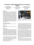
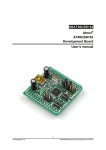
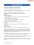
Schematic
October 29, 2015
26
http://www.mattairtech.com/
MT-DB-U2
Manual
Troubleshooting / FAQ
Nothing yet
Support Information
Please check the MattairTech website (http://www.MattairTech.com/) for firmware and software
updates. Email me if you have any feature requests, suggestions, or if you have found a bug. If you
need support, please contact me (email is best). You can also find support information at the
MattairTech website. A support forum is planned. Support for AVRs in general can be found at
AVRfreaks (http://www.avrfreaks.net/). There, I monitor the forums section as the user physicist.
Justin Mattair
MattairTech LLC
PO Box 1079
Heppner, OR 97836 USA
541-626-1531
[email protected]
http://www.mattairtech.com/
Acknowledgments
Thanks to Dean Camera (http://www.fourwalledcubicle.com/) for his excellent LUFA library and
bootloaders. Thanks to the members of AVRfreaks (http://www.avrfreaks.net/) for their support.
Finally, thanks to Atmel for creating a great product, the AVR microcontroller.
October 29, 2015
27
http://www.mattairtech.com/
MT-DB-U2
Manual
Legal
Copyright Notices
Portions of this code are copyright (c) 2009-2013 Justin Mattair (www.mattairtech.com)
This code uses the LUFA USB library Copyright (C) 2013, Dean Camera (www.fourwalledcubicle.com)
and distributed under a modified MIT license (see files).
The CDC and DFU bootloaders are modified versions from LUFA.
The Arduino core files are copyright (c) 2005-2013 David A. Mellis (www.arduino.cc),
copyright (c) 2004-2010 Hernando Barragan (wiring.org.co),
Copyright 2011-2013, Paul Stoffregen, [email protected],
copyright (c) 2006 Nicholas Zambetti,
and copyright (c) 2009 Brett Hagman.
They were modified by Justin Mattair and retain the LGPL 2.1 license (see files).
The Bitlash files are Copyright (C) 2008-2012 Bill Roy (bitlash.net)
They were modified by Justin Mattair and retain the original BSD style license (see files).
Portions of this code are copyright © 2003-2012, Atmel Corporation (http://www.atmel.com/)
Software Warranty Disclaimer
The author disclaim all warranties with regard to this software, including all implied warranties of
merchantability and fitness. In no event shall the author be liable for any special, indirect or
consequential damages or any damages whatsoever resulting from loss of use, data or profits, whether in
an action of contract, negligence or other tortious action, arising out of or in connection with the
use or performance of this software.
Hardware Disclaimer
This development board/kit is intended for use for FURTHER ENGINEERING, DEVELOPMENT, DEMONSTRATION, OR
EVALUATION PURPOSES ONLY. It is not a finished product, and may not (yet) comply with some or any
technical or legal requirements that are applicable to finished products, including, without
limitation, directives regarding electromagnetic compatibility, recycling (WEEE), FCC, CE, or UL
(except as may be otherwise noted on the board/kit). MattairTech LLC supplied this board/kit AS IS,
without any warranties, with all faults, at the buyer's and further users' sole risk. The user assumes
all responsibility and liability for proper and safe handling of the goods. Further, the user
indemnifies MattairTech LLC from all claims arising from the handling or use of the goods. Due to the
open construction of the product, it is the user's responsibility to take any and all appropriate
precautions with regard to electrostatic discharge and any other technical or legal concerns.
The product described in this document is subject to continuous development and improvements. All
particulars of the product and its use contained in this document are given by MattairTech LLC in good
faith. However all warranties implied or expressed including but not limited to implied warranties of
merchantability or fitness for particular purpose are excluded.
This document is intended only to assist the reader in the use of the product. MattairTech LLC shall
not be liable for any loss or damage arising from the use of any information in this document or any
error or omission in such information or any incorrect use of the product.
Trademarks
AVR® is a registered trademark of Atmel Corporation.
All other trademarks are the property of their respective owners.
October 29, 2015
28
http://www.mattairtech.com/
MT-DB-U2
Manual
Appendix A: Precautions
WARNING
Care must be taken when configuring the solder jumpers.
It is possible to cause permanent damage to the device or the
power supply by improperly setting the jumpers.
Do not change any jumpers while the unit is powered.
When using the microcontrollers internal regulator to power itself,
be sure not to exceed the regulator maximum current output.
CAUTION
The MT-DB-U2 contains static sensitive components.
Use the usual ESD procedures when handling.
CAUTION
Improper fuse settings may result in an unusable AVR. Be certain
that you know the effects of changing the fuses, that you
understand the convention used for describing the state of the
fuses (programmed = 0), and that you are using an appropriate
programming speed before attempting to change fuse settings.
October 29, 2015
29
http://www.mattairtech.com/
MT-DB-U2
Manual
Appendix B: Other MattairTech Products
ZeptoProg II AVRISP mkII Programmer
●
●
●
●
●
●
●
●
●
AVRISPmkII compatible AVR Programmer
Supports all AVRs with ISP, PDI, or TPI
Optional 5V output via headers to target board, with
standard jumper and PTC fuse
4channel Logic Analyzer
Serial bridge / pattern generator / SPI interface
GPIO / PWM / frequency input & output
Atmel Studio / AVRDUDE support
Target board voltage of 2V to 5.5V via levelshifted
pins on two main headers
MTDBU6 USB AVR development board
●
●
●
●
●
●
●
●
AT90USB646 / AT90USB1286 USB AVR
64KB/128KB FLASH, 4KB/8KB SRAM
5V, 500mA LDO regulator (3V30V input)
Auto power source selection IC (USB/External)
16MHz and 32.768KHz crystals
Arduino compatible
CDC or DFU bootloader
MTDBX4 USB AVR XMEGA board
●
●
●
●
●
●
●
●
ATxmega128A4U USB XMEGA AVR
128KB FLASH, 8KB SRAM, 2KB EEPROM
3.3V LDO regulator (low quiescent current)
16MHz and 32.768KHz crystals
LED, boot jumper, PDI header
Reset button, mounting holes
USB DFU bootloader preinstalled
MTD21E USB ARM Cortex M0+ board
●
●
●
●
●
●
●
●
October 29, 2015
ATSAMD21E17A or ATSAMD21E18A (32pin)
128KB/256KB FLASH, 16KB/32KB SRAM
Onboard 3.3V, 250mA LDO regulator (2uA quiescent)
16MHz and 32.768KHz crystals
USB connector (power by USB or external up to 15V)
Blue LED, 10pin Cortex header, 2 buttons, I2C
pullups
USB Mass Storage Bootloader (no programmer
required)
30
http://www.mattairtech.com/