1
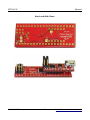
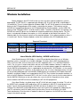
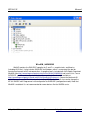
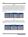
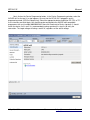
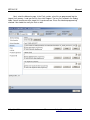
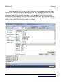
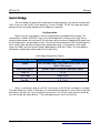
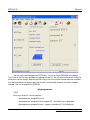
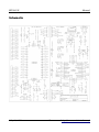
MTX4UX Manual July 21, 2012 1 http://www.mattairtech.com/ MTX4UX Manual Table of Contents Overview........................................................................................................................3 Introduction............................................................................................................... ........................3 MTX4UX Features............................................................................................ ..............................3 ATxmega32a(d)4 Features..................................................................................................... ...........4 Back and Side Views........................................................................................................................ .5 Windows Installation....................................................................................................6 Atmel Studio (AVR Studio) / AVRISP mkII driver........................................................... ....................6 WinAVR / AVRDUDE..................................................................................................................... ....7 MTUX Driver / Serial Configuration....................................................................... ...........................8 Terminal Emulator....................................................................................................... ......................8 Linux Installation..........................................................................................................9 MTX4UX Hardware....................................................................................................10 Top View...................................................................................................................................... ....10 Bottom View....................................................................................................... .............................11 Main Board Pin Descriptions.................................................................................. .........................12 Jumpers............................................................................................................. .............................13 LEDs................................................................................................................... ............................13 Clock Sources.......................................................................................................... .......................14 Reset Button............................................................................................................................. .......14 Sleep Mode................................................................................................................ .....................14 USB Ready Signal.................................................................................................................. .........14 Power Configuration...................................................................................................15 USB Bus Powered............................................................................................................... ............15 Externally Powered – 4.0V to 5.5V........................................................................ ..........................15 Externally Powered – 3.0V to 3.6V........................................................................ ..........................15 AVRISP mkII Compatible Programmer.....................................................................16 Using Atmel Studio (AVR Studio)................................................................................................. ....17 Serial Bridge................................................................................................................22 Configuration........................................................................................................................... ........22 Configuration..............................................................................................................24 Firmware Updates.......................................................................................................25 FLIP...................................................................................................................... ..........................26 Troubleshooting / FAQ................................................................................................28 Support Information...................................................................................................28 Schematic....................................................................................................................29 Legal Information........................................................................................................30 Appendix A: Precautions...........................................................................................32 July 21, 2012 2 http://www.mattairtech.com/ MTX4UX Manual Overview Introduction The MTX4UX is a flexible USB development board for the Atmel ATxmega32a4 or ATxmega32d4 microcontrollers. The XMEGA can be fully programmed over USB using the onboard AVRISPmkIIcompatible PDI programmer. The XMEGA can communicate with a computer using the onboard USB to serial bridge. Speeds up to 2Mbps are supported in synchronous mode (1Mbps in asynchronous mode). The USB AVR, which provides these features, will automatically sleep when USB is disconnected. The board can be powered via USB or an external header. Voltage is regulated by a 3.3V, 500mA LDO regulator. There are several clock options available onboard, including a 32.768KHz crystal, an external 8MHz clock, an external HC49 crystal landing, and several internal clock options. A demo program is preinstalled on the XMEGA demonstrating the USB to serial bridge, RTC, and sleep mode. The MTX4UX comes on a DIL40 size with standard 0.1” header pin spacing. If using an enclosure, there are provisions for external panelmount buttons and USB connector. MTX4UX Features ● ● ● ● ● ● ● ● ● ● ● ● ● ● ● Atmel XMEGA 32A(D)1, 32KB flash, 4KB SRAM, 1KB EEPROM Onboard USB PDI programmer (no external programmer needed) ● AVRISPmkII compatible ● Program flash, EEPROM, fuses, lock bits, and more ● Works with AVR Studio 4 and 5, Atmel Studio 6, AVRDUDE, Codevision, and BASCOM USB Serial Bridge ● Up to 2MHz baud rate (1MHz async) ● Synchronous or asynchronous operation ● Optional USB ready signal 3.3V, 500mA LDO regulator Powered via USB or external header 32.768KHz crystal connected to TOSC (RTC) pins 8MHz external clock available from USB AVR HC49 crystal landing connected to XTAL pins PDI header* 4 boot modes selectable via 2 jumpers (or via panelmount buttons) ● USBUART bridge (default) ● AVRISPmkII compatible PDI programmer ● Configuration (uses terminal emulator) ● DFU bootloader (to update firmware on USB AVR via USB) Reset button can be used to toggle between the PDI programmer and the serial bridge Preloaded demo program demonstrates the USB to serial bridge, RTC, and sleep mode PCB measures 5.2cm x 2.05cm (DIL40 with standard 0.1” pin spacing) Compatible with Windows XP/Vista/7 and Linux Uses LUFA USB library and AVRISPmkII by Dean Camera (http://www.lufa-lib.org/) July 21, 2012 3 http://www.mattairtech.com/ MTX4UX Manual ATxmega32a(d)4 Features ● ● ● ● ● ● ● Highperformance, Lowpower 8/16bit AVR® XMEGA Microcontroller NonVolatile Program and Data Memories 32K Bytes of InSystem SelfProgrammable Flash 4K Bytes Boot Section with Independent Lock Bits 1 KB EEPROM 4 KB Internal SRAM Peripheral Features Fourchannel DMA Controller with support for external requests (ATxmega32a4 only) Eightchannel Event System (four channels on ATxmega32d4) Five 16bit Timer/Counters (four on ATxmega32d4) 3 Timer/Counters with 4 Output Compare or Input Capture 2 (1 on ATxmega32d4) Timer/Counters with 2 Output Compare or Input Capture HighResolution Extension on all Timer/Counters Advanced Waveform Extension on two Timer/Counters Five USARTs (two on ATxmega32d4) IrDA modulation/demodulation for one USART Two 2Wire Interfaces w/ dual address match (I2C and SMBus) Two SPI (Serial Peripheral Interface) peripherals AES and DES Crypto Engine (ATxmega32a4 only) 16bit Real Time Counter with separate Oscillator One 12channel, 12bit, 2 Msps (200Ksps on ATxmega32d4) Analog to Digital Converters One Twochannel, 12bit, 1 Msps Digital to Analog Converters (ATxmega32a4 only) Two Analog Comparators with Window compare function External Interrupts on all General Purpose I/O pins Watchdog Timer with Separate Onchip Ultra Low Power Oscillator Special Microcontroller Features Poweron Reset and Programmable Brownout Detection Internal and External Clock Options with PLL and Prescaler Programmable Multilevel Interrupt Controller Sleep Modes: Idle, Powerdown, Standby, Powersave, Ext. Stby. Advanced Programming, Test and Debugging Interface PDI (Program and Debug Interface) 34 Programmable I/O Lines Operating Voltage (MTX4 operates at 3.3V) 1.6 3.6V Speed performance (MTX4 can operate at 032MHz) 0 12 MHz @ 1.6 3.6V 0 32 MHz @ 2.7 – 3.6V July 21, 2012 4 http://www.mattairtech.com/ MTX4UX Manual Back and Side Views July 21, 2012 5 http://www.mattairtech.com/ MTX4UX Manual Windows Installation Before plugging in the MTX4UX for the first time, the latest software and drivers must be downloaded. The MTX4UX is supported under Windows XP, Vista (32 and 64 bit), and Windows 7 (32 and 64 bit). There is limited support for Windows 2000. The MTX4UX appears as three different devices to the PC depending on which mode is selected by the jumpers. These devices are the AVRISP mkII compatible programmer, the DFU bootloader for firmware updates, and the USB CDC device (virtual COM port) which is used for all other modes. Therefore, three drivers are required. The AVRISP mkII and DFU drivers are included with software available on the Atmel website. The CDC driver is included with Windows, but requires an .inf file available on the MattairTech website. The following table lists the minimum versions of the required software. If the software provides a driver, is is listed as well. See the Firmware Updates section for installation of the DFU bootloader driver. Required Downloads Software Version Driver URL MTX4UX Driver latest CDC driver http://www.mattairtech.com/software/MattairTech_CDC.inf AVR Studio / Atmel Studio 4.19, 5.x, or 6.x AVRISPmkII http://www.atmel.com/tools/AVRSTUDIO4.aspx OR http://www.atmel.com/tools/ATMELAVRSTUDIO.aspx Atmel Studio (AVR Studio) / AVRISP mkII driver Atmel Studio (formerly AVR Studio) is a free IDE provided by Atmel that runs on Windows operating systems. It includes an assembler, debugger, simulator, and an AVR chip programming utility. As of June 2012, there are three main versions supported, the 4.x, 5.x, and Atmel Studio 6.x series. The 4.x series is mature and stable, and can run on older hardware, however, it requires the use of the WinAVR gcc toolchain, which is out of date. It also lacks proper support for newer devices, like the XMEGA microcontrollers, but is a good option for older devices. AVR Studio 4.x is also smaller and less demanding on PC resources. If you choose to use the 4.x series, download version 4.19. You will also need to download and install WinAVR 20100110 prior to installation of AVR Studio. Both AVR Studio 5.x and Atmel Studio 6.x are supported by the MTUX. They includes the compiler toolchain, as well as the AVR Software Framework (ASF). Use the 5.x or 6.x series if you wish to use newer devices like the XMEGA. Whichever version you choose, be sure to install the Jungo drivers when asked, which include the AVRISP mkII driver needed by the MTUX AVR programmer. Once Atmel Studio is installed, plug in the MTX4UX with only jumper A installed. This will run the AVRISP mkII compatible AVR programmer. LED A should be lit and LED B should be pulsing on and off. You will then be prompted for the AVRISP mkII driver. By default, this is located in the Program Files/Atmel/AVR Jungo USB directory. Point the installer to the appropriate subdirectory for your PC architecture (usb32 or usb64) and install the driver. Do not use the driver in the AVR Tools/usb directory. Once the driver is loaded, the device will appear as the AVRISP mkII device under Jungo in the device manager. July 21, 2012 6 http://www.mattairtech.com/ MTX4UX Manual WinAVR / AVRDUDE WinAVR contains the GNU GCC compiler for C and C++, compiler tools, and libraries (including AVR Libc). It also includes AVRDUDE for Windows, which is a command line tool for transferring firmware to AVR microcontrollers. A graphical tool is included with AVR Studio. Download WinAVR from http://sourceforge.net/projects/winavr/files/WinAVR/20100110/ and install it first. To use AVRDUDE, you will need to download and install an update to libusbwin32 available at http://sourceforge.net/projects/libusbwin32/files/libusbwin32releases/. Choose the libusbwin32 develfilterx.x.x.x.exe file. Do this only after installing AVR Studio. You will also need to change the MTUX AVRISP mkII Programmer host configuration to AVRDUDE (configuration mode). Note that WinAVR is outdated. It is not recommended for newer devices like the XMEGA series. July 21, 2012 7 http://www.mattairtech.com/ MTX4UX Manual MTUX Driver / Serial Configuration Next, the MTUX CDC driver can be installed, which is used by the serial bridge and configuration mode. This driver allows the board to appear as a COM port. The driver itself is included with Windows, but an .inf file is needed to configure it. Download the .inf file from http://www.mattairtech.com/software/MattairTech_CDC.inf. Now, plug in the MTUX with no jumpers installed. This will run configuration mode. Only LED A will be lit. Windows will then prompt you for the MTUX CDC driver. Point the installer to the directory where you downloaded the driver and install. Note that you may need to rename the driver in order for it to show up in the installer. Windows may add the .txt extension to the file after downloading. Rename it so that it ends with .inf. Ignore any warnings given by the installer (ie: unsigned driver). Once the driver is loaded, the device will appear as the MTUX CDC device using a COM port in the device manager. There is no need to configure serial port parameters. The buad rate, for example, is ignored. The MTUX will always communicate with the computer at full speed (up to 2Mbps). If you experience any buffering problems, for example, a delayed response to user input, then change both buffer sizes to 1. Terminal Emulator Finally, the terminal emulator can be configured. Windows XP includes HyperTerminal, which has been tested with the MTUX and will be documented here. There are several other terminal emulators available freely on the Internet. If you wish to use any of them, it should be no trouble to adapt the instructions presented here. Next, start HyperTerminal. Create a new connection. You will refer to this connection again, so give it an appropriate name (after it is configured, you can copy it to your desktop). Select the MTUX COM port (ie: COM4) and continue. It is not necessary to configure the baud rate or any other serial parameters. Now, click on the connect icon. After connecting, you may see garbage on the terminal screen. If this is the case, click on the configuration icon and change the emulation to ANSI (or ANSIW). The configuration mode requires an ANSI terminal to allow drawing of the menu system. Normally, when first entering a mode that uses the CDC driver, a message that reads “Press any Key” is printed periodically. If you do not see this message, just press any key to continue. It is important to always click the disconnect icon before switching to the AVR Programmer. Then click the connect icon a couple seconds after returning. This is required because changing to the AVRISPmkII driver unloads the CDC driver, then loads the AVRISPmkII driver. In order for the terminal to use the same COM port as before, it must be disconnected when returning to the CDC driver so that it does not assign a new COM port. July 21, 2012 8 http://www.mattairtech.com/ MTX4UX Manual Linux Installation Linux is supported as well. You must download and build the toolchain from the latest script available at AVR Freaks on the AVR GCC Forum (Script for building AVR GCC sticky at http://www.avrfreaks.net/index.php?name=PNphpBB2&file=viewtopic&t=42631). All firmware written for the MTX4UX is developed under Linux using this toolchain. Drivers TODO (drivers should already be installed) GCC Toolchain TODO (see opening paragraph) AVRDUDE TODO (ie: avrdude p x32a4 c avrisp2 P usb U flash:w:"myfirmware.hex") dfuprogrammer TODO (must use version 0.5.2 or higher) Terminal Emulator TODO (can use minicom, config port (ie: /dev/tty/ACM0), save config, run with minicom o) July 21, 2012 9 http://www.mattairtech.com/ MTX4UX Manual MTX4UX Hardware Top View July 21, 2012 10 http://www.mattairtech.com/ MTX4UX Manual Bottom View J1: Connects USB module CLKO to XMEGA pin R1 J2: Connects USB module RX/D to XMEGA pin D3 J2: Connects XMEGA pin R1 to header J3: Connects XMEGA pin R0 to header July 21, 2012 11 http://www.mattairtech.com/ MTX4UX Manual Main Board Pin Descriptions Pin Description A0A7, B0B3 Analog / GPIO pins (port A and port B) Consult datasheet for functionality. Agnd Analog ground Avcc This is connected to 3.3V through a ferrite bead Gnd Ground 3.3V By default, this pin outputs 3.3V from the onboard regulator. This pin is connected to Vcc of each board. 3.3V can be supplied externally on this pin if Jumper 1 and Jumper 2 on the USB module are desoldered. 5V By default, this pin outputs 5V from USB Vbus. This pin is connected to the input of the onboard 3.3V regulator. 5V can be supplied externally on this pin if Jumper 3 on the USB module is desoldered. Note that 5V is unused on the main board. It only connects to USB Vbus and the regulator input on the USB module (through Jumper 3 and Jumper 1 respectively). C0C7 GPIO pin (Port C) Consult datasheet for functionality. D0 D7 GPIO pins (Port D) Consult datasheet for functionality. D1 This pin is connected to XCK on the USB module. XCK is used during PDI programming. It is also used by the USBUART bridge if it is in synchronous mode. If configured, this line can also signal when USB is ready by pulling the line low. When USB is not ready or disconnected, the line will tristate. The XMEGA must enable the pullup on this pin if using the USB ready signal. D2 This pin is connected to TX on the USB module. It is used during PDI programming as well as by the USBUART bridge. D3 This pin is connected to RX/D on the USB module through Jumper J4 on the main board. It is used during PDI programming as well as by the USB UART bridge. E0 E3 GPIO pins (Port E) Consult datasheet for functionality. R0 By default, this pin is disconnected. Solder jumper J3 on the main board to connect to R0. This can be used for GPIO if an external crystal is not used. R1 By default, this pin is disconnected. Solder jumper J2 on the main board to connect to R1. This is useful for supplying an external clock signal. Note that an external 8MHz clock is available from the USB module CLKO pin. Solder jumper J1 on the main board to connect this clock to R1. This can be used for GPIO if an external crystal or clock is not used. RST This pin is connected to RESET on the XMEGA. This line is routed to the PDI header, the RESET button, and to the USB module as well. Pressing reset will reset the XMEGA as well as toggle the USB module between the PDI programmer and USBUART bridge. July 21, 2012 12 http://www.mattairtech.com/ MTX4UX Manual Jumpers There are three jumpers on the USB module. Two are used to select one of four modes of operation, and one can be used to reset the USB AVR. Jumpers are used, rather than buttons, to save board space and allow the connection of external buttons (for example, panel mount buttons). Jumper A is next to LED A , Jumper B is in the center, and RESET is next to LED B. The mode is selected when powering the board. Additionally, the mode can be toggled between the PDI programmer and USBUART bridge by pressing the RESET button on the main board. The reset jumper on the USB module is only connected to the USB AVR reset input. There is a 10K pullup on this line. A jumper cap can be used to reset the USB module, but it is mainly intended for an external button. External buttons/switches can also be connected to the mode selection jumpers. The following table lists the jumper functionality. Jumper Functionality Jumper A Jumper B Mode Installed Not Installed AVRISP mkII Programmer Not Installed Installed Configuration Not Installed Not Installed Serial Bridge Installed Installed DFU Bootloader LEDs There are two green LEDs that are used to indicate the mode of operation, communication activity, and programmer status. The following table lists LED functionality in each mode. When an LED is used to display communication activity, the default state of the LED is shown on the left. For example, during serial bridge RX activity, the LED blinks off for a short time then returns to the default on state. LED Functionality Mode / App LED A LED B AVR Programmer On / Programmer Activity PWM pulsing Configuration On Off USBUART Bridge On / RX Activity On / TX Activity DFU Bootloader Off On July 21, 2012 13 http://www.mattairtech.com/ MTX4UX Manual Clock Sources By default, a 32.768KHz crystal is installed and connected to the TOSC pins of the XMEGA (R0 and R1). An HC49 crystal landing is available as well. Because the TOSC and XTAL inputs share the same pins (R0 and R1), only one crystal option can be installed at a time. Note that the load capacitors are 6pF, which is appropriate for the default 32.768KHz crystal. There are two external clock options. The first is the 8MHz clock available from the USB module CLKO pin. Solder jumper J1 connects this clock to the XMEGA external clock input pin (R1). The second option is an offboard clock (connect solder jumper J2 to route R1 to a header pin). There are several internal clock options as well. The demo program makes use of the 32MHz internal RC oscillator. This oscillator is configured to autocalibrate using the DFLL, which uses the 32.768KHz crystal as input. The crystal is also the source for the RTC. A 2MHz RC oscillator and two different 32KHz oscillators are also available. A PLL and prescalers can be used to obtain the various clocks. Reset Button The Reset button on the main board is connected to the XMEGA reset pin. A 10K pullup resistor pulls RESET up to Vcc (3.3V). The reset line is used during PDI programming, so it is routed to the PDI header and the USB module. The reset button can also be used to toggle the USB module between the PDI programmer and USBUART bridge, which is useful for debugging. 3 PDI Header The PDI header has the standard 6pin layout. Because an onboard programmer is provided, an external programmer is not necessary. However, debugging requires use of an external debugger connected to the PDI header. Because the XMEGA TX pin (USB AVR RX/D pin) is connected to the XMEGA PDI_DATA pin, the debugger cannot be used when using TX as this would cause contention. However, solder jumper J4 can be disconnected to avoid contention, but TX will then be disconnected from the USB module. TX will still available on the header pin. When using an external debugger or programmer, the USB module should be in any mode other than the PDI programmer. Sleep Mode The USB AVR will enter sleep mode when the USB host suspends it, or when USB is disconnected. If using USB poweronly cable (no USB signals), then the USB AVR will enter sleep. The mode of sleep, powerdown or standby, can be set in the configuration. Powerdown will reduce power consumption to a minimum, by stopping the crystal oscillator and the CLKO output. In both sleep modes, both LEDs will be turned off. USB Ready Signal The USB ready signal, if enabled, is useful when the target needs to know when the USB cable is disconnected or the USB bus suspended. The signal is opendrain activelow from the XCK pin. The XMEGA must enable the pullup on this line before reading it. If it reads low, USB is enumerated and ready. When in sleep mode, or when USB is connected but not yet enumerated, it will read high. If synchronous operation in used, the XCK clock signal will override this. July 21, 2012 14 http://www.mattairtech.com/ MTX4UX Manual Power Configuration WARNING Care must be taken when configuring the solder jumpers. It is possible to cause permanent damage to the device or the target board by improperly setting the jumpers, or by supplying an incorrect external voltage (if used). Do not change any solder jumpers while the unit is powered. The MTX4UX can be powered in a variety of ways by utilizing 3 solder jumpers. By default, the board is configured to be powered via USB. At all times, 3.0V3.6V must be supplied on the 3.3V pin. By default, this is provided by the onboard 3.3V regulator on the back of the PCB. The following table lists some of the configurations. Power Configuration Jumper J1 Jumper J2 Jumper J3 Regulator USB bus powered (default) Externally powered – 4.0 to 5.5V Externally powered – 3.0 to 3.6V Soldered Soldered Not Soldered Soldered Soldered Not Soldered Soldered Not Soldered Doesn't Matter Used Used Not Used USB Bus Powered This is the default configuration. Vbus is connected to the 5V rail (J3). The regulator input is connected to the 5V rail (J1) and the regulator output is connected to the 3.3V rail (J2). The regulator output is also connected to Vcc of both the main board and the USB module. Externally Powered – 4.0V to 5.5V A voltage from 4.0V to 5.5V can be supplied externally to the 5V pin. In this case, desolder J3 to disconnect USB Vbus from the 5V rail. This external voltage can optionally be supplied to the onboard 3.3V regulator input through J1. Externally Powered – 3.0V to 3.6V A voltage from 3.0V to 3.6V can be supplied externally to the 3.3V pin. In this case, desolder both J1 and J2 to disconnect the onboard 3.3V regulator from the 5V and 3.3V rails. USB Shield Jumper J4 on the USB module can be soldered to connect the USB shield to ground. The USB specification calls for the USB shield to be connected to ground on the host side only. However, it may be desired to ground this on the device side. An 0603 SMT component may be soldered as well. July 21, 2012 15 http://www.mattairtech.com/ MTX4UX Manual AVRISP mkII Compatible Programmer The MTUX AVR Programmer is based on the AVRISP mkII compatible programmer written by Dean Camera (http://www.fourwalledcubicle.com/). It supports programming of all Atmel AVR microcontrollers with an ISP, PDI, or TPI programming interface. These include the megaAVR series (ISP), the tinyAVR series (ISP, TPI), the XMEGA series (PDI), the USB AVRs (ISP), and the listed CAN and PWM AVRs (see Appendix B for device listing). AVR Studio 4.19, 5.x, Atmel Studio 6.x, and AVRDUDE are supported. See hardware section for details on the pinouts. Programming speeds of up to 8MHz are supported in ISP mode. However, current AVRs require a programming speed less than ¼ of the target clock speed. For 20MHz AVRs, this is 4MHz. For 16MHz, 2MHz is the limit. It is not recommended to operate at exactly ¼ of the target frequency, especially when programming fuses, as this can cause them to become incorrectly set and possibly render the AVR useless (unless parallel programming is available). Note that many AVRs come from the factory with the clock source set to the internal 8MHz oscillator and with the CKDIV8 fuse programmed, resulting in a clock speed of 1MHz. In these cases, the ISP programming speed should be set to 125KHz or less until CKDIV8 is unprogrammed and power cycled. For all modes, the 8MHz clock output can be connected to the target clock input and used as a recovery clock. This is useful, for example, to allow resetting of fuses that were misconfigured to use an external clock when intending to use a crystal or internal oscillator. The MTUX supports target devices operating at 3.0V to 5.5V. The voltage of the outputs from the MTUX is determined by the voltage present on the Vcc power input pin. This voltage is usually provided by the MTUX, which can supply either 5.0V or 3.3V. Alternatively, the target board can supply this voltage. In either case, Vcc and ground must be connected to the target board. Consult the Hardware section for details. All outputs from the MTUX have 300ohm series resistors that limit current and control overshoot and ringing. July 21, 2012 16 http://www.mattairtech.com/ MTX4UX Manual Using Atmel Studio (AVR Studio) Start Atmel Studio and open or create a new project. The following screenshots from Atmel Studio 6 show the MTX1S_Simple_Demo template for the MattairTech MTX1S ATxmega128A1 development board. July 21, 2012 17 http://www.mattairtech.com/ MTX4UX Manual Next, click on the Device Programming button. In the Device Programming window, select the AVRISP mkII as the tool. If no tool appears, be sure that the MTX4UX is plugged in and in programming mode (LED B will be pulsing). Select the appropriate device and either ISP, PDI, or TPI as the interface and click Apply. You should now be connected to the AVRISP mkII compatible programmer with serial number 000200012345. Now click Read next to Device signature. It should match the device if all is well. It is recommended to always perform this step first to verify the connection. The target voltage will always read 3.3V, regardless of the actual voltage. July 21, 2012 18 http://www.mattairtech.com/ MTX4UX Manual Next, select the Memories page. In the Flash section, a hex file can programmed into the targets flash memory. Load your hex file, then click Program. The hex file is located in the Debug folder. You will need to erase the target first if you do not have “Erase Flash before programming” checked. You should also verify the flash as well. July 21, 2012 19 http://www.mattairtech.com/ MTX4UX Manual Next, click on the Fuses tab. It is best to leave the fuse settings alone until you understand what they do. In particular, if using ISP, do not program RSTDISBL or unprogram SPIEN, as this will lock you out of the target chip. Do not set the BOD (Brownout detection) voltage to a level above the target chip voltage, as this will cause the target to be held perpetually in reset. You must also be careful with the clock settings as well. If you select the wrong clock source, then your target chip will not operate if the configured clock source is not present. However, the MTUX provides a clock output which can be used to recover from this situation (see above). July 21, 2012 20 http://www.mattairtech.com/ MTX4UX Manual Now you may wish to look at the other pages. Note that any firmware upgrade feature should not be used. The MTX4UX programmer is not an actual AVRISP mkII, it just emulates one, so you should not attempt to update the MTX4UX firmware using Atmel Studio. Any firmware updates will be posted to the website and loaded using FLIP or dfuprogrammer. Using AVRDUDE TODO (ie: avrdude p x32a4 c avrisp2 P usb U flash:w:"myfirmware.hex") July 21, 2012 21 http://www.mattairtech.com/ MTX4UX Manual Serial Bridge The serial bridge can connect the target board to a host application (ie: terminal emulator) over USB. On the host side, the MTUX will appear as a virtual COM port. The MTUX simply relays bytes between the host and target. Speeds of up to 2Mbps are supported. Configuration Before using the serial bridge, it must be configured to be compatible with the target. This configuration is stored in EEPROM. There is no need to duplicate the settings on the host side, as communication between the host and MTUX will always be the maximum supported USB speed, and the other parameters are ignored by the host. Only the connection between the MTUX and target use these settings. Note that when configuring the speed to be manual, it is possible to set the speed higher than 2MHz, but the maximum speed supported by the USB link is 2MHz. The serial bridge is configured in configuration mode (jumper A off, jumper B on). Serial Bridge Configuration Options Configuration Option Possible Values Speed 2M, 1M, 500K, 250K, 125K, 76.8K, 57.6K, 38.4K, 19.2K, 9600, 2400, manual Baud Rate Register 0x0000 0x0FFF (if manual selected as speed) Clock 2X 1X, 2X Clock Mode async, sync Data Bits 5, 6, 7, 8, 9 When in synchronous mode, the MTUX is the master, so the XCK pin is enabled as an output. The target board must enable its clock pin as an input and be configured as a slave. When using 9bit data frames, two bytes are sent or received for every frame. The first byte simply contains the 9th bit, thus the first byte will always be 0 or 1. The second byte contains the rest of the 8 bits. July 21, 2012 22 http://www.mattairtech.com/ MTX4UX Manual Baud Rate Register Value (Manual Speed) Async 1X f osc −1 16∗BAUD UBRR= f osc 16∗UBRR1 BAUD= UBRR= BAUD= Async 2X Synchronous f osc −1 8∗BAUD UBRR= f osc 8∗UBRR1 BAUD= f osc −1 2∗BAUD f osc 2∗UBRR1 where f osc =8000000 July 21, 2012 23 http://www.mattairtech.com/ MTX4UX Manual Configuration The MTUX programmer, serial bridge, and other features can be configured by entering configuration mode. This configuration is stored in nonvolatile EEPROM memory. Configuration mode requires an ANSI terminal emulator. Configuration options are highlighted by using the up and down arrow keys, and selected using the enter key. Some dialogs are for entering numbers in hexadecimal. Here, the left arrow key, right arrow key, and backspace can be used. The following lists the structure of the menu system: ● ● ● Serial Speed ● List of selectable speeds: 2400, 9600, 19.2K, 38.4K, 50.0K, 76.8K, 125K, 250K, 500K, 1M, 2M ● Manual (when selected, configure using Manual Settings below) Manual Settings ● Baud Rate Register ● Clock 2X ● (USB ready signal is opendrain active low on XCK pin from USB AVR) Disabled or Enabled AVRISPmkII ● (Which sleep mode is used when USB is disconnected or suspended) Power Down or Standby Ready Signal ● ● (async mode only) Asynchronous or synchronous Sleep Mode ● ● (enter value in hex) Serial Mode ● ● (Serial bridge speed selection) (select which software will be interfacing with the MTX4UX PDI programmer) AVR Studio or AVRDUDE Credits (displays list of firmware authors) The AVRISP mkII programmer has two configuration options. The first is the selection of the host application, which can be either AVR Studio or AVRDUDE. This is required because these two modes use a slightly different USB endpoint configuration. If you are using Linux, then this setting will not matter, as they both work with AVRDUDE for Linux (AVR Studio is not available for Linux). The USB AVR automatically enters sleep mode when the USB cable is disconnected or the USB bus is suspended. Sleep mode is by default set to Power Down, which provides for the lowest current consumption. Otherwise, the 8MHz CLKO output will be disabled during sleep. The USB ready signal is useful when the target needs to know when the USB cable is disconnected or the USB bus suspended. The signal is opendrain activelow from the XCK pin, which may also be used for synchronous serial operation. The target must enable the pullup on this line before reading it. If it reads low, USB is enumerated and ready. Otherwise, it will read high. If synchronous operation in used, the XCK clock signal will override this. July 21, 2012 24 http://www.mattairtech.com/ MTX4UX Manual Firmware Updates The MTUX firmware will be updated periodically to add new features and fix bugs. These updates will be available on the MattairTech website. The updates may include just a hex file (for programming flash), or both a hex file and eep file (for programming both flash and EEPROM). FLIP is a graphical utility for Windows used to load firmware updates onto the MTUX. FLIP includes the DFU bootloader driver. Download FLIP 3.4.2 or higher from http://www.atmel.com/tools/FLIP.aspx and install. If required to install a signed driver, then consult the table below for the download link. Note that all units sold after May 22, 2012 use the ATmega32U2. Downloads required for Firmware Updates Software Version Driver URL MTUX Firmware latest (ATmega32U2) N/A http://www.mattairtech.com/software/MT_UX/MT_UX.hex MTUX Firmware latest (At90USB162) N/A http://www.mattairtech.com/software/MTX4/MT_X4_UX.hex FLIP 3.4.2 + Signed DFU Driver latest DFU driver http://www.atmel.com/tools/FLIP.aspx DFU driver http://www.avrfreaks.net/index.php?module=Freaks%20Acade my&func=viewItem&item_type=project&item_id=2196 Once FLIP is installed, the DFU bootloader driver can be loaded. Press and hold both buttons while plugging in the MTUX to run the DFU bootloader. LED A should be off and LED B should be on. Windows will then prompt you for the ATmega32U2 (or AT90USB162) driver. By default, this is located in the Program Files/Atmel/Flip 3.4.2/usb directory. Once the driver is loaded, the device will appear as the ATmega32U2 (or AT90USB162) device under Atmel USB Devices in the device manager. July 21, 2012 25 http://www.mattairtech.com/ MTX4UX Manual FLIP Plug in the MTX4UX with both jumpers installed. This will enter the DFU bootloader. LED A should be off and LED B should be on. Now launch the FLIP utility. When it has loaded, click on the chip icon and select the ATmega32U2 (AT90USB162). Next, click on the USB icon, select USB, then connect. The screen should now show information about the ATmega32U2 (AT90USB162). Click on the File menu, and open the appropriate hex file. More information will appear about the program. Be sure that erase is checked. The MTUX firmware cannot be loaded unless the flash is erased first. Uncheck Blank Check, as it is not supported. Program must be checked. Verify must be unchecked. Reading of the flash is not allowed, so verification is not possible. Verification is less useful when programming over USB anyway, as USB provides error detection and correction. Now click on the Run button in the lowerleft of the screen, and the firmware will be quickly loaded onto the MTUX. If you encounter problems, then you will need to unplug the MTUX, disconnect FLIP, and start over making certain that the above settings are observed. July 21, 2012 26 http://www.mattairtech.com/ MTX4UX Manual You may also need to program the EEPROM. If so, click on Select EEPROM at the bottom. Then, click on the File menu and open the appropriate eep file. You will have to change the file filter to allow you to see the eep file. Note that eep files are just hex files but with the eep extension instead of hex. More information will appear about the file when selected. Both Program and Verify should be checked. Click run to program the EEPROM. dfuprogrammer TODO Must erase chip first. Cannot read flash. dfuprogrammer atmega32u2 erase dfuprogrammer atmega32u2 flasheeprom MT_UX120401.eep (if applicable) dfuprogrammer atmega32u2 flash suppressvalidation MT_UX120401.hex July 21, 2012 27 http://www.mattairtech.com/ MTX4UX Manual Troubleshooting / FAQ Nothing yet Support Information Please check the MattairTech website (http://www.MattairTech.com/) for firmware and software updates. Email me if you have any feature requests, suggestions, or if you have found a bug. If you need support, please contact me (email is best). You can also find support information at the MattairTech website. A support forum is planned. Support for AVRs in general can be found at AVRfreaks (http://www.avrfreaks.net/). There, I monitor the forums section as the user physicist. Justin Mattair MattairTech LLC PO Box 1079 Heppner, OR 97836 USA 541-626-1531 [email protected] http://www.mattairtech.com/ Acknowledgments Thanks to Dean Camera (http://www.fourwalledcubicle.com/) for his excellent LUFA library, AVRISPmkII clone, and DFU bootloader, all of which are used in the MTUX firmware. Thanks to the members of AVRfreaks (http://www.avrfreaks.net/) for their support. Finally, thanks to Atmel for creating a great product, the AVR microcontroller. July 21, 2012 28 http://www.mattairtech.com/ MTX4UX Manual Schematic July 21, 2012 29 http://www.mattairtech.com/ MTX4UX Manual Legal Information Copyright Notices Copyright © 2009-2012, Justin Mattair (http://www.mattairtech.com/) Copyright © 2009-2012, Dean Camera (http://www.lufa-lib.org) Copyright © 2003-2011, Atmel Corporation (http://www.atmel.com/) Software Disclaimer The author(s) disclaim all warranties with regard to this software, including all implied warranties of merchantability and fitness. In no event shall the author(s) be liable for any special, indirect or consequential damages or any damages whatsoever resulting from loss of use, data or profits, whether in an action of contract, negligence or other tortious action, arising out of or in connection with the use or performance of this software. Hardware Disclaimer This development tool is intended for use for FURTHER ENGINEERING OR DEVELOPMENT PURPOSES ONLY. It does not comply with some or any technical or legal requirements that are applicable to finished products, including, without limitation, directives regarding electromagnetic compatibility, recycling (WEEE), FCC, CE, or UL (except as may be otherwise noted). MattairTech LLC supplied this development product AS IS, without any warranties, with all faults, at the buyer's and further users' sole risk. The user assumes all responsibility and liability for proper and safe handling of the goods. Further, the user indemnifies MattairTech LLC from all claims arising from the handling or use of the goods. Due to the open construction of the product, it is the user's responsibility to take any and all appropriate precautions with regard to electrostatic discharge and any other technical or legal concerns. The product described in this document is subject to continuous development and improvements. All particulars of the product and its use contained in this document are given by MattairTech LLC in good faith. However all warranties implied or expressed including but not limited to implied warranties of merchantability or fitness for particular purpose are excluded. This document is intended only to assist the reader in the use of the product. MattairTech LLC shall not be liable for any loss or damage arising from the use of any information in this document or any error or omission in such information or any incorrect use of the product. Trademarks AVR® is a registered trademark of Atmel Corporation. All other trademarks are the property of their respective owners. July 21, 2012 30 http://www.mattairtech.com/ MTX4UX Manual Licenses LUFA USB Library Copyright 2012 Dean Camera (dean [at] fourwalledcubicle [dot] com) Permission to use, copy, modify, distribute, and sell this software and its documentation for any purpose is hereby granted without fee, provided that the above copyright notice appear in all copies and that both that the copyright notice and this permission notice and warranty disclaimer appear in supporting documentation, and that the name of the author not be used in advertising or publicity pertaining to distribution of the software without specific, written prior permission. The author disclaim all warranties with regard to this software, including all implied warranties of merchantability and fitness. In no event shall the author be liable for any special, indirect or consequential damages or any damages whatsoever resulting from loss of use, data or profits, whether in an action of contract, negligence or other tortious action, arising out of or in connection with the use or performance of this software. July 21, 2012 31 http://www.mattairtech.com/ MTX4UX Manual Appendix A: Precautions WARNING Care must be taken when configuring the solder jumpers. It is possible to cause permanent damage to the device or the target board by improperly setting the jumpers, or by supplying an incorrect external voltage (if used). Do not change any solder jumpers while the unit is powered. Do not power an XMEGA device with greater than 3.6V. Do not supply the 3.3V rail (if externally supplied) with a voltage outside the range of 3.0V to 3.6V. CAUTION The MT-X4-UX contains static sensitive components. Use the usual ESD procedures when handling. For example, touch a grounded metal object prior to handling. July 21, 2012 32 http://www.mattairtech.com/