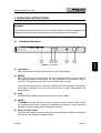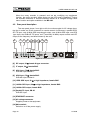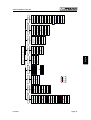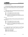
1
99 Washington Street
Melrose, MA 02176
Phone 781-665-1400
Toll Free 1-800-571-8431
Visit us at www.TestEquipmentDepot.com
MO-180
MODULADOR SFN/MFN DVB-T/H
SFN/MFN DVB-T/H MODULATOR
- 0 MI1505 -
SAFETY NOTES
Read the user’s manual before using the equipment, mainly " SAFETY RULES "
paragraph.
The symbol
on the equipment means "SEE USER’S MANUAL". In this
manual may also appear as a Caution or Warning symbol.
Warning and Caution statements may appear in this manual to avoid injury
hazard or damage to this product or other property.
USER’S MANUAL MO-180
TABLE OF CONTENTS
1 GENERAL .................................................................................................................. 1
1.1 General description........................................................................................... 1
1.2 Functional description....................................................................................... 2
1.3 Specifications.................................................................................................... 4
2 SAFETY RULES ...................................................................................................... 9
2.1 General safety rules.......................................................................................... 9
2.2 Descriptive Examples of Over-Voltage Categories......................................... 11
4 OPERATING INSTRUCTIONS ................................................................................ 15
4.1 Front panel description ................................................................................... 15
4.2 Rear panel description.................................................................................... 16
4.3 Menu functions ............................................................................................... 17
4.4 MODULATOR functions ................................................................................. 20
4.5 NETWORK functions ...................................................................................... 24
4.6 SYNC functions .............................................................................................. 26
4.7 FILTERING functions...................................................................................... 27
4.8 RF functions.................................................................................................... 27
4.9 LEVEL functions ............................................................................................. 28
4.9.1 Non-Linear Pre-Distorter functions .......................................................... 29
4.9.2 Crest Factor Reduction functions CFR Mode .......................................... 35
4.10 TEST functions ............................................................................................... 35
4.11 CONFIGURATION functions .......................................................................... 36
4.12 STATUS functions .......................................................................................... 38
4.13 Remote control via Ethernet ........................................................................... 40
4.13.1 Assigning an IP address .......................................................................... 40
4.13.2 Setting up a virtual serial port .................................................................. 43
4.13.3 Serial control commands ......................................................................... 46
4.14 DVB-T/H useful bit rates ................................................................................. 47
4.15 Error Information............................................................................................. 50
4.15.1 Error messages on the top menu level .................................................... 57
5 MAINTENANCE ....................................................................................................... 59
5.1 Mains fuse replacement.................................................................................. 59
5.2 Cleaning Recommendations........................................................................... 59
APPENDIX A: Channel Plans
English
3 INSTALLATION ....................................................................................................... 13
3.1 Power Supply.................................................................................................. 13
3.1.1 Operation using the Mains ....................................................................... 13
3.2 Installation and Start-up.................................................................................. 13
USER’S MANUAL MO-180
SFN/MFN DVB-T/H MODULATOR
MO-180
1
1 GENERAL
1.1
General description
The MO-180 supports 2k, 4k and 8k modes, as well as hierarchical
transmission, and it could be used in Multi Frequency Networks (MFN) and Signal
Frequency Networks (SFN). Digital coding and modulation are implemented by means
of programmable logic devices using intellectual property developed by PROMAX. This
makes the design highly flexible, allowing to tailor it to any particular application, and
offering plenty of features at low cost.
Highlights of this product are:
1
•
Fully compliant with the DVB-T/H standard.
•
Seamless automatic switching between DVB-ASI inputs.
•
2k, 4k and 8k carriers.
•
Hierarchical and non-hierarchical modulations.
•
SFN and MFN (Master and Slave operation) modes.
•
Filtering of up to 16 TS PIDs.
•
Channel bandwidth of 5, 6, 7 and 8 MHz (user selectable).
•
Locks to internal/external 10 MHz reference or to incoming TS data rate.
•
Frequency agile (resolution of 1 Hz).
•
Crest factor reduction followed by non-linear pre-distortion.
•
High MER (> 38 dB in RF typical, > 43 dB in IF typical).
Trade Mark of the DVB Digital Video Broadcasting Project (4660).
01/2008
Page 1
English
The MO-180 is an SFN/MFN DVB-T/H modulator fully compliant with the DVBT/H standards ETSI EN 300 744 v1.5.1 (including annex F referring to DVB-H), ETSI
TS 101 191 v1.4.1 (SFN synchronisation) and ETSI EN 300 468 v1.8.1 (DVB-SI). The
modulator inputs consist of an MPEG-2 transport stream (TS) in DVB-SPI or DVB-ASI
format, a 10 MHz GPS reference and a 1pps GPS reference. The GPS inputs are used
in combination with the Megaframe Initialisation Packet (MIP) embedded in the
transport streams for SFN synchronisation purposes. The outputs are DVB-T/H signals
COFDM-modulated and up-converted to IF and RF.
USER’S MANUAL MO-180
1.2
Functional description
The MO-180 is a professional SFN/MFN DVB-T/H modulator contained in a 19"
1U chassis. The unit has three selectable MPEG-2 TS inputs (two serial ASI inputs and
one parallel SPI input). Either of these inputs can be used to modulate the COFDM
signal in both hierarchical (one TS input) and non-hierarchical (two TS inputs) modes.
An additional test TS can be generated internally in the modulator. This allows to
generate compliant DVB-T/H signals even in the absence of a valid TS input.
The modulator has a one pulse per second GPS input (1pps) and a 10 MHz
GPS input. These are used in combination with the Megaframe Initialization Packet
(MIP) carried in the transport streams to achieve synchronisation inside an SFN
network. The 10 MHz input can also be used in MFN networks to frequency lock the IF
and RF outputs to a common reference. A loop-through 10 MHz output is also
available. The input impedance of both the 1pps and 10 MHz inputs can be set to 50 Ω
or high impedance.
In MFN networks we can operate the modulator in master and slave modes. In
slave MFN mode, the useful bit rate at the TS input to the COFDM modulator has to be
the one defined in document ETSI EN 300 744 for each choice of DVB-T/H
transmission parameters. The modulator automatically synchronises its internal clock
to the incoming TS packet rate. The slave mode allows to use one TS input with
constant bit rate in non-hierarchical modes. When using hierarchy, the user has to
choose which TS (HP or LP) the selected TS input is mapped to. This is the stream the
modulator actually synchronises to. The other hierarchical TS is generated internally as
a PRBS test sequence.
The input bit rate in slave mode should be within 0.1‰ of the values specified in
the DVB-T/H standard (see Section 4.14 for actual figures) and approximately
constant. This operating mode is useful when re-modulating an off-air DVB-T/H signal
with the same parameters without the need to demultiplex and re-multiplex the
transport stream (as it would be the case in master mode).
The lock-in range of the MO-180 with respect to the TS rate is typically greater
than that of a COFDM demodulator. It’s thus possible that the modulator is perfectly
synchronised in slave mode and, however, a DVB-T/H receiver is unable to acquire
sync.
Page 2
01/2008
Test Equipment Depot - 800.517.8431 - 99 Washington Street Melrose, MA 02176
FAX 781.665.0780 - TestEquipmentDepot.com
USER’S MANUAL MO-180
In master MFN mode, the modulator is locked to either the internal 10 MHz
TCXO clock reference or to the external 10 MHz GPS reference. In this mode, the
MO-180 is able to work with any incoming bit rate as long as the net bit rate resulting
from dropping all NULL packets present in the stream is strictly lower than the value
given in the DVB-T/H specification for the modulation parameters in use (see
Section 4.14). The input TS bit rate is adapted (bit rate adaptation) to the useful bit rate
required by the DVB-T/H signal by stuffing the TS with NULL packets (packet stuffing).
This stuffing process alters the sequence of PCR values embedded in the TS. These
values have to be re-stamped for the resultant PCR jitter to remain within the limits
specified by the DVB. In hierarchical modes, operating the MO-180 as master has the
added advantage over the slave mode of being able to use any of the three TS inputs
as the HP input, LP input or both.
In SFN mode, the modulator can be locked to either the external 10 MHz GPS
reference, or to the internal 10 MHz TCXO, or to the input HP TS data rate. A loss of
sync with the external 10 MHz reference can be used to trigger a swap of the
synchronisation over to the input TS rate. This reduces the number of disruptions to the
output IF/RF COFDM signals. Periodic or a periodic MIP packets are constantly
monitored in the HP TS input so as to dynamically adjust the delay of the modulator for
accurate SFN synchronisation. If required, a positive or negative delay offset with
100-ns resolution can be added locally.
In non-hierarchical transmissions the modulator can be instructed to seamlessly
switch between ASI inputs when it detects a loss of sync in the currently selected TS
input. Additionally, in SFN operation the IF/RF outputs of the modulator can be
optionally muted in the presence of processing errors.
The modulator can be configured to generate any of the transmission modes
listed in the DVB-T/H specification. In hierarchical modes, the HP and LP streams can
be encoded with different convolution code rates. The channel bandwidth can be set by
the user to 5, 6, 7 or 8 MHz as required by the application. Several test modes are
available in the MO-180 (blanking of carriers, single tone output, test TS generation,
CBER and VBER injection).
Many of the configuration parameters can be optionally obtained from the MIP
packet embedded in the input transport stream. This can be done in both MFN and
SFN operation. By setting the Transmitter ID of the modulator we can extract from the
MIP the configuration parameters which are addressed to a particular transmitter and
which may differ from those of the rest of the network. The ID and centre frequency of
the network can be updated in the corresponding entries of the Network Information
Table (NIT).
01/2008
Page 3
English
Whenever possible, in master MFN mode it is advised to use an input bit rate
considerably lower than the nominal value given in the DVB-T/H specification.
Otherwise, an input rate too close to the required value might eventually lead to
overflow of the TS packet buffer implemented in the modulator.
USER’S MANUAL MO-180
In MFN operation, the MO-180 is capable of filtering out up to 16 Program
Elementary Streams (PES) identified by their PIDs. The MPEG-2 TS is not actually remultiplexed because the TS tables are not updated, only the PES’s are eliminated to
help reduce the bit rate. This feature finds its application in, for example, transmodulating a high-bit-rate DVB-S or DVB-C signal to DVB-T/H.
DVB-H specific options are native or in-depth interleaving for 2k and 4k carriers,
and signalling of the use of time slicing and/or MPE-FEC in any of the modulated
transport streams via the TPS bits transmitted in the COFDM signal. Although also
optional in DVB-T, the cell ID is a mandatory parameter that needs to be defined for
any DVB-H signal.
The modulator is frequency agile. The user can select an RF output frequency
between 45 and 875 MHz in steps of 1 Hz. In normal operation, the IF output frequency
is internally set by the modulator and varies between 32 and 36 MHz depending on the
selected RF frequency. The RF output can be switched off, in which case the IF
frequency is fixed at 36 MHz. The polarity of the IF/RF spectrum (inverted or noninverted) can be selected by the user. The spectrum of the COFDM signal is spectrally
shaped using a raised cosine window in order to reduce the amount of out-of-band
spurious components. There is a trade-off between the size of the window and the
reduction in adjacent channel interference. The choice of window size has been
optimised for each combination of FFT and guard interval lengths.
The MO-180 has been designed to work in both Multi Frequency Networks
(MFN) and Single Frequency Networks (SFN). The MER measured at IF is typically
above 43 dB regardless of the channel bandwidth. In RF the typical MER that can be
measured with a high-end DVB-T/H receiver lies above 38 dB.
The operation of the MO-180 is done via the front panel LCD display and
controls. The modulator can be easily configured by navigating through a rather
intuitive set of menus. A couple of LEDs located on the front panel signal the existence
of errors in the modulator or whether the equipment is properly powered.
1.3
Specifications
INPUTS
MPEG-2 Transport Stream
GPS Inputs
10 MHz input
Page 4
Two DVB-ASI inputs, 75 Ω female BNC.
One DVB-SPI input, LVDS DB-25.
TS packets of length 188 or 204 bytes
(automatic detection).
Support for burst and continuous packet mode.
High impedance / 50 Ω female BNC.
Min. 50 mV, max. +3.3V.
01/2008
USER’S MANUAL MO-180
1pps input
Synchronisation
Master MFN
High impedance / 50 Ω female BNC.
Selectable active edge (high or low).
Minimum 2 V, max. 5 V.
Internal 10 MHz TCXO or external 10 MHz GPS
reference.
Input TS bit rate strictly below the value given in
the DVB-T/H specification.
Packet stuffing for bit rate adaptation and PCR
re-stamping are carried out automatically.
Slave MFN
Input TS bit rate constant and equal to the value
given in the DVB-T/H document ±0.1‰
(no stuffing).
SFN
External 10 MHz reference or input TS data rate.
Automatic seamless switching between ASI
inputs in the event of a sync loss.
Type
Frequency range
Spectrum polarity
Power level (average)
In-band amplitude ripple
In-band group delay ripple
Frequency stability
Out-of-band spectral
characteristics1
@ ± 3.805 MHz
@ ± 4.25 MHz
@ ± 5.25 MHz
IQ amplitude imbalance
IQ quadrature error
Central carrier suppression
Harmonics and spurious
MER
Muting in the presence
of errors
50 Ω BNC female connector.
Variable between 32 and 36 MHz in steps of
1 Hz; fixed at 36 MHz when RF output is off.
Selectable via front panel controls.
0 dBm (107 dBµV on 50 Ω), fixed
< 0.2 dB
< 10 ns
Better than 2 ppm
0 dBc
—46 dBc (2k), —56 dBc (4k), —56 dBc (8k)
—56 dBc
< 0.02%
< 0.02º
< —55 dBc
< —60 dBc
> 43 dB
SFN only
1
Frequencies are referred to the central frequency for an 8 MHz channel. Peak levels measured using a 3 kHz
bandwidth are referred to the carriers located on either side of the spectrum. Values shown are the worst case and
correspond to guard intervals of 1/32.
01/2008
Page 5
English
IF OUTPUT
USER’S MANUAL MO-180
RF OUTPUT
Type
Frequency range
Spectrum polarity
Power level (average)
50 Ω N-type female connector.
Adjustable between 45 and 875 MHz in 1 Hz
steps.
Selectable via front panel controls.
Approximately -27 dBm on 50 Ω with no
attenuation. Variable attenuation of 0 to 60 dB in
steps of 1 Db.
Level of harmonics and
spurious
< —50 dBc.
Frequency stability
Better than 5 ppm.
MER
> 38 dB typical.
Phase noise
Better than —94 dBc/Hz @ 1 kHz.
Muting in the presence of errors SFN only.
DVB-T/H PARAMETERS
Number of carriers
Guard intervals
Code rates (HP&LP)
Symbol interleaver
Constellations
Hierarchical modes
Network topology
TPS signalling
Channel bandwidth
Parameter extraction
PROCESSING DELAYS
MFN
SFN
TEST MODES
Carrier blanking
Pilot carriers
Page 6
2k, 4k, 8k.
1/4, 1/8, 1/16, 1/32.
1/2, 2/3, 3/4, 5/6, 7/8.
Native and in-depth (2k & 4k DVB-H only).
QPSK, 16QAM, 64QAM.
16QAM and 64QAM constellations with
constellation ratio α = 1, 2 or 4.
MFN and SFN.
Cell ID, DVB-H’s time-slicing and MPE-FEC.
5, 6, 7 and 8 MHz.
MIP packet or local programming
The static delay may be adjusted between 0 and
1 second with a resolution given by the DVB-T/H
elementary clock period.
Dynamic delay automatically calculated from the
10 MHz GPS reference, the 1pps signal and the
MIP packet embedded in the HP TS multiplex.
The resolution is 100 ns.
A positive or negative local delay offset may be
added as long as the total delay is never greater
than 1 s or lower than the inherent latency of the
modulator
Synchronisation accuracy better than ±200 ns.
Rough estimate of the network delay from the
SFN adapter output to the modulator TS inputs
Blank a number of carriers (start index to stop
index) within the COFDM ensemble.
Generate the pilot carriers only (continual and
TPS).
01/2008
USER’S MANUAL MO-180
TS packet generation
PRBS generation
Bit error injection
CREST FACTOR REDUCTION
Crest Factor range
NON-LINEAR PRE-DISTORTER
Correction bandwidth
Number of correction points
AM-AM table
AM-PM table
Generate a single carrier at the channel central
frequency whose level equals the average
COFDM output power or is set to the maximum
available. This is intended for signal level
alignment
Internal generation of test TS using PRBS
sequences of length 15 or 23 embedded within
NULL packets as specified in document ETSI TR
101 290.
Map a PRBS sequence into constellation points
following the guidelines of document ETSI TR
101 290.
Inject bit errors at the input to the constellation
mapper (results in a non-zero CBER before the
Viterbi decoder) or at the input to the
convolutional encoder (results in a non-zero
VBER after the Viterbi decoder).
8 to 11 dB in 0.1 dB steps.
> 3⋅the DVB-T/H complex sample rate2
2 to 16 using linear interpolation
—12 dB to +12 dB for the abscissae, —6 dB to +6
dB for the ordinates, both in 0.1 dB steps
—12 dB to +12 dB for the abscissae in 0.1 dB
steps, —30° to +30° in steps of 0.1° for the
ordinates
ETHERNET INTERFACE
Connector
Standard
RJ45 with activity indicator LEDs.
10BASE-T or 100BASE-TX (auto-sensing).
POWER SUPPLY
Voltage
Frequency
Consumption
100 — 130 VAC; 200 — 250 VAC
50 - 60 Hz.
20 W.
OPERATING ENVIRONMENTAL CONDITIONS
Indoor use only
Altitude
Up to 2000 m
Temperature range
From 0°C to 40 °C
Max. relative humidity
80 % (up to 31°C),decreasing linearly up to 50%
at 40 °C
2
For instance, for an 8 MHz channel the correction bandwidth is greater than 3 x 64/7 = 27.4 MHz.
01/2008
Page 7
Test Equipment Depot - 800.517.8431 - 99 Washington Street Melrose, MA 02176
FAX 781.665.0780 - TestEquipmentDepot.com
English
Single carrier
USER’S MANUAL MO-180
MECHANICAL FEATURES
Dimensions
Weight
Page 8
19" (W.) x 1.75" (H.) x 15" (D.)
6.5 kg
01/2008
USER’S MANUAL MO-180
2 SAFETY RULES
2.1
General safety rules
*
The safety could not be assured if the instructions for use are not closely
followed.
*
Use this equipment connected only to systems with their negative of
measurement connected to ground potential.
*
This is a class I equipment, for safety reasons plug it to a supply line with the
corresponding ground terminal
*
This equipment can be used in Overvoltage Category II installations and
Pollution Degree 1 environments.
*
When using some of the following accessories use only the specified ones to
ensure safety.
English
Power cord CA005
*
Observe all specified ratings both of supply and measurement.
*
Remember that voltages higher than 70 V DC or 33 V AC rms are dangerous.
*
Use this instrument under the specified environmental conditions.
*
The user is only authorized to carry out the following maintenance operations:
Replace the fuses of the specified type and value.
On the Maintenance paragraph the proper instructions are given.
Any other change on the equipment should be carried out by qualified personnel.
*
The negative of measurement is at ground potential.
*
Do not obstruct the ventilation system of the instrument.
*
Use for the signal inputs/outputs, specially when working with high levels,
appropriate low radiation cables.
*
Follow the cleaning instructions described in the Maintenance paragraph.
01/2008
Page 9
USER’S MANUAL MO-180
*
Symbols related with safety:
DIRECT CURRENT
ALTERNATING CURRENT
DIRECT AND ALTERNATING
GROUND TERMINAL
PROTECTIVE CONDUCTOR
FRAME TERMINAL
EQUIPOTENTIALITY
ON (Supply)
OFF (Supply)
DOUBLE INSULATION
(Class II Protection)
CAUTION
(Risk of electric shock)
CAUTION REFER TO MANUAL
FUSE
Page 10
01/2008
USER’S MANUAL MO-180
2.2
Descriptive Examples of Over-Voltage Categories
Low voltage installations isolated from the mains
Cat II
Portable domestic installations
Cat III
Fixed domestic installations
Cat IV
Industrial installations
English
Cat I
01/2008
Page 11
USER’S MANUAL MO-180
Page 12
01/2008
Test Equipment Depot - 800.517.8431 - 99 Washington Street Melrose, MA 02176
FAX 781.665.0780 - TestEquipmentDepot.com
USER’S MANUAL MO-180
3 INSTALLATION
3.1
Power Supply
The MO-180 is an equipment powered through the mains for its operation.
3.1.1 Operation using the Mains
Connect the instrument to the mains through the AC voltage connector [15]
located on the MO-180 rear panel.
Check if the mains voltage is according to the equipment specifications.
3.2
Installation and Start-up
Switch the main switch [16] located in the rear panel to position I (power on).
After a successfully start up, the equipment emits four acoustic tones to indicate that it
is ready to begin operation. When the equipment is connected to the mains, the green
LED LINE [3] remains lit.
Please see Sections 4.1 y 0 for a description of the front and rear panels.
01/2008
Page 13
English
The MO-180 modulator is designed for use as a rack-mounted 19 inches device
(1U chassis).
USER’S MANUAL MO-180
Page 14
01/2008
USER’S MANUAL MO-180
4 OPERATING INSTRUCTIONS
WARNING:
The following described functions could be modified based on software updates of the
equipment, carried out after manufacturing and the publication of this manual.
Front panel description
1
2
3
4
5
English
4.1
Figure1.- Front panel
[1] LCD display
With 2x40 characters crisply clear due to its white LED backlight.
[2] ERROR
RED LED has a couple of functions. For each operating second, the first tenth of
that second indicates whether there are sync problems in the modulator (ON) or
not (OFF). Examples are loss of TS sync or invalid input bit rates.
The remaining nine tenths of a second, the RED LED shows whether errors lasting
more than 5 seconds (since the last time the error counter was cleared) are
detected (ON).
[3] LINE
A GREEN LED indicator shows when the power supply is ON.
[4] MENU
The MENU key allows the user to enter and exit the menu functions, and to modify
the equipment functional parameters (modulation parameters, output frequency
and level, and other configuration and setup functions).
[5] Rotary encoder button.
This has many different functions: Moving accross the different display menus and
sub-menus, and validating selected options.
01/2008
Page 15
USER’S MANUAL MO-180
When the rotary encoder is pressed, and we are modifying any equipment
function, the option currently being shown on the LCD panel is selected. Turning
the encoder clockwise or counter clockwise allows us to navigate through each
menu function and option available in the MO-180.
4.2
Rear panel description
The rear panel shows, from right to left, the mains socket for AC voltage input,
the fan air outlet, an RJ-45 connector for remote control via Ethernet, a parallel DVBSPI TS input, one 10 MHz GPS loop-through output, one 10 MHz GPS input, one GPS
1pps input, two DVB-ASI TS inputs, an IF (nominally 36 MHz) output and the main RF
output, at the frequency and level chosen by the user.
6
7
8
9
13 14
15 16
Figure 2.- Rear panel view.
[6] RF output, 50 Ω, female N-type connector.
[7] IF output, 50 Ω, female BNC.
[8] ASI1 input, 75 Ω, female BNC.
DVB-ASI input number 1.
[9] ASI2 input, 75 Ω, female BNC.
DVB-ASI input number 2.
[10] 1PPS GPS input, 50 Ω or high impedance, female BNC.
[11] 10 MHz GPS input, 50 Ω or high impedance, female BNC.
[12] 10 MHz GPS output, female BNC.
[13] Parallel TS input, DB-25
DVB-SPI input.
[14] ETHERNET connector.
[15] AC voltage connector
Supplies power to the equipment.
[16] Mains switch
Switch on or off the power supply.
Page 16
01/2008
USER’S MANUAL MO-180
NOTE: The actual IF frequency value varies between 32 and 36 MHz, depending on
the RF frequency. When a fixed 36 MHz is needed, the RF output of the
modulator has to be disabled in the RF menu.
4.3
Menu functions
After start up, the equipment display shows information regarding the main
operating conditions, as can be seen in the following example:
FREQ: 650000000 Hz ATT: 10 dB
FFT:8K CONST:64QAM BW:8 MHz GUARD:1/4
Here the RF frequency is 650 MHz, the 1-dB step RF attenuator is set to 10 dB,
the DVB-T/H signal has 8K carriers, occupies 8 MHz and uses a 64 QAM constellation
with a guard interval of 1/4. No test mode is selected (NONE) and the operation mode
of the MO-180 is set to master. Packets of length 204 bytes are currently being
detected on the selected TS input.
After a few seconds, the display changes its contents to show the working time
and error count information, as follows:
MO-180 PROMAX ELECTRONICA, S.A.
Working: 01:13:55 ERR: 0
The text on the upper line (the name of the company, in the example above)
could be customised via the remote control port to the user’s needs, allowing for an
easy identification of the equipment or for some piece of advice.
The main display alternates every 5 seconds the previous information with the
following:
TS SPI: 19.432Mbps
Working: 01:14:12 ERR: 0
This represents an averaged estimate of the net bit rate of the selected
transport stream. That is, in slave mode or SFN operation this is directly the raw bit rate
of the input TS as it arrives at the modulator. In master MFN operation, this is the bit
rate of the TS resulting from stripping the input TS off all NULL packets. In the case
that the input contains only NULL packets, the estimated bit rate will be effectively 0
Mbps! The bit rate estimate is expressed in Mbps with three decimal places, i.e. with a
resolution of 1 kbps.
01/2008
Page 17
Test Equipment Depot - 800.517.8431 - 99 Washington Street Melrose, MA 02176
FAX 781.665.0780 - TestEquipmentDepot.com
English
FREQ: 650000000 Hz ATT: 10 dB
TEST: NONE TS: Master (204)
USER’S MANUAL MO-180
Pressing the MENU key, allows us to enter the main menu level. Pressing
MENU again, takes us to the main status display. This main menu level uses the first
text line to give some advice on the operation assigned to each control, and the second
line to display the selectable options and functions.
MENU: back PUSH: select TURN: next/prev.
MODULATOR
Turning the encoder clockwise or counter-clockwise cycles through the submenu
entries. The menu tree is hierarchically organised as shown in the chart on page 19.
Page 18
01/2008
01/2008
Value in microseconds
Transmitter ID:
1 − 65535
Network ID:
0 − 65535
Update Net ID:
OFF, ON
Centre Fre quency:
OFF, Alpha = 1, 2, 4
HP/LP code rate :
Conste llation:
QPSK, 16QAM, 64QAM
Guard Inte rva l:
1/ 4,, 1/8, 1/16, 1/32
FFT Mode: 2k, 8k, 4k
OFF, ON
NO, YES
English
NLPD Mode:
Dis able:
8 to 11 dB in 0. 1-dB steps
CFR V alue:
OFF, ON
VBER va lue:
CBER value :
Valid carrier index
Stop Carrier:
Valid carrier index
Start Carrier:
NONE, CBER, VBER,
Blank Carriers, Pilots only,
PRBS/TR-290
Mode:
TEST
Value in Hz
Ma xim um Delay:
Value in ms
Tx Tim e Offset:
Value in microseconds
HP/LP Net Dela y:
Value in dBm
Tx Radia ted Powe r:
Tx Fre quency Offs et:
Valid value
OFF, ON
Gatew ay IP:
1pps Error:
Valid number
None, HP, LP, HP&LP
MIP Error:
None, HP, LP, HP&LP
MIP Loss :
Current Equipment Config.
SW/FW/O PT:
NO, YES
Clear Errors :
Access to error list
Error Lis t:
STATUS
IP Mask:
Valid number
IP Address:
COFDM, Tone MAX or RMS
IF Mode:
CCIR, STD L, OIRT, UHF
Channel Plan:
0 – 10
Load f rom Memory :
0 – 10
Save to Mem ory:
CONFIGURATION
Native, In-depth
Sym bol Interl.:
OFF, HP, LP, HP&LP
Tim e S licing:
OFF, HP, LP, HP&LP
MPE-FEC:
Valid TS ID
HP TS ID:
Valid NIT ID
NIT Netw ork ID:
COLOUR KEY
DVB-H only
MFN only
SFN only
–31 t o +32
Number from Channel Plan
CFR Mode:
Fine Adjust :
0 to 60 dB in 1-dB steps
Cha nnel:
At tenuat ion:
45,000, 000 to 875, 000,000
LEVEL
Fre quency (1-Hz res.):
RF
Value in microseconds
PID 16: 1 − 8191
PID 15: 1 − 8191
PID 02: 1 − 8191
PID 01: 1 − 8191
Mode: OFF, ON
FILTERING
Mode: DVB-T, DVB-H
OFF, ON
Update Centre Freq.:
1pps Zin: High, 50 ohm
1pps e dge: Rise, Fall
10MHz Zin: High, 50 ohm
Int, Ext, Auto1, Auto2
10MHz reference:
SYNC
Cell ID: 0 − 65535
HP, LP
Slave mode TS lock :
Master, Slave
TS sync m ode:
PRBS bits: 23, 15
ON, O FF
Spectral Inversion:
Frequency in 10 Hz steps
Loc al dly offset:
1/ 2, 2/3, 3/4, 5/6, 7/8
Local, MIP
Hie rarchy:
Modula tor Config.:
Mode: MFN, SFN
NETWORK
BW (MHz) : 8, 7, 6, 5
ASI1, ASI 2, SPI, PRBS
HP/LP TS Input:
MODULATOR
......
TS SPI: 19.432Mbps
Working: 01:14:12 ERR: 0
USER’S MANUAL MO-180
Page 19
USER’S MANUAL MO-180
4.4
MODULATOR functions
At this menu level, the modulator parameters can be modified and customised
to the user’s needs. When modifying any modulation parameter, changes became
active only when confirmed by pressing the encoder function. Instead, pressing the
MENU key allows us to cancel the change of option. Let’s comment on each function.
HP TS Input
Selects the input used for providing a High Priority (HP) Transport Stream (TS)
to the COFDM modulator. Note that in non-hierarchical transmissions, this is the only
TS input to the modulator. Options are:
ASI1
ASI2
SPI
PRBS
Use TS provided at ASI1 input connector (rear panel).
Use TS provided at ASI2 input connector (rear panel).
Use parallel TS provided by SPI connector (rear panel).
Internal test TS at an appropriate bit rate consisting of NULL packets
filled with a 15- or 23- bit PRBS sequence as indicated by menu entry
“MODULATOR:PRBS bits”.
LP TS Input
Selects the input used for providing a Low Priority (LP) Transport Stream (TS)
to the COFDM modulator. Note that in non-hierarchical transmissions, this input is not
used. Options are:
ASI1
ASI2
SPI
PRBS
Use TS provided at ASI1 input connector (rear panel).
Use TS provided at ASI2 input connector (rear panel).
Use parallel TS provided by SPI connector (rear panel).
Internal test TS at an appropriate bit rate consisting of NULL packets
filled with a 15- or 23- bit PRBS sequence as indicated by menu entry
“MODULATOR:PRBS bits”.
BW
This option enables output channel bandwidth selection. The COFDM signal
can be generated with a BW of 6 MHz, 7 MHz and 8 MHz. In DVB-H
(“MODULATOR:Mode” set to DVB-H) a further 5 MHz option appears in this menu.
8 MHz
7 MHz
6 MHz
5 MHz
Page 20
Selects an 8 MHz bandwidth.
Selects a 7 MHz bandwidth.
Selects a 6 MHz bandwidth.
Selects a 5 MHz bandwidth (DVB-H only).
01/2008
USER’S MANUAL MO-180
Hierarchy
Using this function the COFDM modulator is switched between hierarchical
mode, with different alpha constellation ratios, and non-hierarchical mode operation.
The options available are:
OFF
Non-hierarchical operation
α=1
Hierarchical constellation with α = 1
α=2
Hierarchical constellation with α = 2
α=4
hierarchical constellation with α= 4
HP Code Rate
Using this function, the user can modify the convolutional code rate for the High
Priority (HP) Transport Stream (TS). The available options are 1/2, 2/3, 3/4, 5/6 and
7/8.
Using this function, the user can modify the convolutional code rate for the Low
Priority (LP) Transport Stream (TS). The available options are 1/2, 2/3, 3/4, 5/6 and
7/8.
Constellation
Here the menu allows the selection of one of the available constellations. Note
than in hierarchical modes QPSK is not a valid choice. The options are QPSK, 16QAM
and 64QAM.
Guard Interval
This function selects the required guard interval for the COFDM signal. The
available values are 1/4, 1/8, 1/16 and 1/32.
FFT Mode
Selection of the required FFT value (number of carriers in the COFDM
ensemble). The modulator has these options:
2K
8K
4K
01/2008
2048 carriers, 1705 active
8192 carriers, 6817 active
4096 carriers, 3409 active. DVB-H operation only (menu entry
“MODULATOR:Mode” must be set to DVB-H).
Page 21
English
LP Code Rate
USER’S MANUAL MO-180
Spectral Inversion
This function allows inversion of the spectrum generated in IF and RF. As the IF
spectrum is by itself inverted compared to the RF output, the inversion applied is
related to the RF output. The possible options are:
OFF
ON
Carriers with lower indices occupy the lower frequencies of the RF
channel.
Carriers with higher indices occupy the lower frequencies of the RF
channel.
PRBS bits
Selection of the length in bits of the internally generated pseudorandom sequences:
23
15
PRBS sequences of length 223—1 as documented in TR 101 290.
PRBS sequences of length 215—1 as documented in TR 101 290.
TS sync mode
In MFN mode, this selects the mode of operation of the modulator with respect
to the incoming TS (see Section 1.2 for further details):
Master The bit rate of the input TS must be lower than the useful bit rate for the
choice of DVB-T parameters in use.
Slave The input bit rate must equal the useful bit rate.
Slave mode TS lock
In slave MFN mode, this selects the TS input to which the modulator locks its
internal clock. Options are:
HP
LP
The modulator is synchronised with the HP TS.
The modulator is synchronised with the LP TS (hierarchical modes only).
Cell ID
This number from 0 to 65535 serves to identify the cell from which the DVB-T/H
signal comes from. Its main application is in DVB-H though its use is optional in DVB-T.
Page 22
01/2008
Test Equipment Depot - 800.517.8431 - 99 Washington Street Melrose, MA 02176
FAX 781.665.0780 - TestEquipmentDepot.com
USER’S MANUAL MO-180
Mode
DVB-H only features are enabled and available through the menu system when
the TPS length indicator is set to 33 bits. Otherwise, DVB-T is used as marked by the
TPS length indicator being 31 bits. The two extra bits in DVB-H flag the use of time
slicing and MPE-FEC (see below). Options are:
DVB-T (31 TPS bits) DVB-T mode with a TPS length indicator of 31 bits.
DVB-H (33 TPS bits) DVB-H mode with a TPS length indicator of 33 bits.
MPE-FEC
In DVB-H, this configures the Multi-Protocol Encapsulation / Forward Error
Correction (MPE-FEC) used on top of the DVB-T channel coding. The available options
are:
MPE-FEC not used.
The HP TS uses MPE-FEC.
The LP TS uses MPE-FEC.
Both the HP and LP TS use MPE-FEC.
Time slicing
In DVB-H this indicates whether any of the HP or LP transport streams use time
slicing:
OFF
HP
LP
HP&LP
Time slicing is not used
At least one elementary stream within the HP TS uses time slicing.
At least one elementary stream within the LP TS uses time slicing.
At least one elementary stream within both the HP and LP TS’s uses
time slicing.
Symbol Interl.
In DVB-H, this selects between the 2k or 4k native symbol interleaver and the
DVB-H-only in-depth symbol interleaver. For 8k, the native interleaver is mandatory.
Native Mandatory in DVB-T and 8k DVB-H.
In-depth New symbol interleaver introduced in 2k & 4k DVB-H modes.
01/2008
Page 23
English
OFF
HP
LP
HP&LP
USER’S MANUAL MO-180
4.5
NETWORK functions
The selection of this item allows us to access those functions related to the
configuration of the modulator to operate in an MFN or SFN network. Let’s review each
option.
Mode
Choose whether the modulator is to be used in a Single Frequency Network
(SFN) or in a Multi-Frequency Network (MFN). In an SFN the modulator synchronises
its internal clock with an external 10 MHz reference or with the input HP transport
stream in case an external 10 MHz reference is missing. Proper SFN synchronisation
requires a Megaframe Initialisation Packet (MIP) in the incoming TS (or in both
transport streams in the case of hierarchical transmissions) and a one-pulse-persecond (1pps) reference. In an MFN, the modulator is synchronised with either the
chosen input TS (slave mode) or with the internal/external 10 MHz reference (master
mode).
MFN
SFN
Multi-frequency network with mater or slave synchronisation.
Single frequency network with external synchronisation.
Modulator config.
Some parameters of the modulator (constellation, symbol interleaver,
hierarchical modes with parameter α, HP & LP convolutional rates, guard interval,
number of carriers, time slicing, MPE-FEC, cell ID and channel bandwidth) may be
configured using the values carried on the MIP packet. This applies to both MFN and
SFN operation.
Local
MIP
Configure the modulator using the values entered by the user.
Configure the modulator using the MIP packet.
Local dly offset
In MFN this is the non-negative local delay offset to add to the intrinsic latency
of the modulator. The valid range goes from a few ms (the exact number depends on
the channel bandwidth, number of carriers, guard interval and symbol interleaver
depth) up to 1 second. In SFN this is the positive or negative local delay offset that we
add to the dynamic delay automatically calculated by the modulator using the MIP
packet, the 1pps signal and the 10 MHz reference clock. The valid range for this offset
in SFN is such that the total delay (calculated as the dynamic delay plus the local delay
offset plus the transmitter delay offset embedded in the MIP) lies between a few ms
and 1 second. The minimum delay depends on the same parameters as in MFN. When
the total delay is below the minimum or above the maximum (although clipped at 1s),
this is flagged by the modulator as an error. The local delay offset can be set with a
resolution of 100 ns.
Page 24
01/2008
USER’S MANUAL MO-180
Transmitter ID
This number identifies a single transmitter inside an SFN or MFN network. This
ID can be used in combination with the MIP packet to address a specific transmitter
site in order to configure some of its parameters (such as time delay offset, RF
frequency offset, radiated power, user-defined private data, cell ID, bandwidth other
than 6, 7 and 8 MHz) regardless of what the configuration for the rest of the network
might be. An ID of 0 designates all transmitters and thus cannot be use to single out a
transmitter.
Network ID
This number serves as a unique identification code for DTT networks. The
allocation of these codes may be found in document ETSI ETR 162. When
“NETWORK:Update NET ID” is ON, the network ID in the actual NIT table (that is, the
network of which the TS containing the NIT is part) is replaced with the network ID
specified here. The CRC of the NIT table is updated accordingly and the NIT version
number is increased by 1.
The two available options are ON and OFF. When this is set to ON, the
network_id field found in the NIT of the actual network (NIT with table_id = 0x40) is
replaced with the Network ID specified with the menu entry “NETWORK:Network ID”.
Centre Frequency
This represents the centre frequency that replaces the value currently stored in
the NIT when “NETWORK:Update Centre Freq.” is ON. This frequency is expressed in
10 Hz units.
Update Centre Freq.
When this entry is set to ON, the 32-bit centre_frequency and frequency fields
found
within
NIT
descriptors
terrestrial_delivery_system_descriptor
and
cell_frequency_link_descriptor, respectively, of the actual network (NIT with table_id =
0x40) are replaced with the value specified in menu entry “NETWORK:Centre
Frequency”. The incoming 32-bit CRC field and NIT version are updated accordingly.
Note that for the descriptor cell_frequency_link_descriptor (which contains a complete
list of cell IDs and frequencies in use in these cells for the TS multiplex described) we
pair the centre frequency with the cell ID being currently broadcast using the TPS bits.
This cell ID might in turn be either the one extracted from the MIP packet or,
alternatively, the one defined with the menu entry “MODULATOR:Cell ID”.
01/2008
Page 25
English
Update Net ID
USER’S MANUAL MO-180
4.6
SYNC functions
These set of functions control all synchronisation features of the MO-180. In the
following the available menu entries are described.
10 MHz reference
This applies to master MFN and SFN operation. In slave MFN operation the
modulator clock is always derived from the input TS rate. Several lock modes are
defined:
Ext
SFN and master MFN. The modulator locks its circuitry to the external
10 MHz input. This might be for instance the clock obtained from the
GPS signal by an external professional GPS receiver.
Int
Master MFN only. Use the internal 10 MHz TCXO for synchronisation.
Auto1
Master MFN only. The automatic switch over type 1 defaults to the
external 10 MHz reference, switching over to the internal TCXO when an
external reference is missing. Once the loss of the external 10 MHz
reference has triggered the switch over to the internal 10 MHz clock, the
10 MHz loss flag will remain active until a switch over back to the
external reference is forced by selecting Auto1 again.
Auto2
SFN and Master MFN. The automatic switch over type 2 works similarly
to Auto1. The only difference is that a loss of sync triggers the
switchover to a TS data derived clock which is locked to the incoming
HP stream as in MFN slave mode.
10 MHz Zin
The input impedance seen from the 10 MHz BNC connector can be set to 50 Ω
or to High Z (several MΩ).
1pps edge
In SFN operation this selects the active edge of the one pulse per second
signal. The rising edge is commonly used.
1pps Zin
In SFN operation, the input impedance seen from the 1pps BNC connector can
be set to 50 Ω or to High Z.
Page 26
01/2008
USER’S MANUAL MO-180
4.7
FILTERING functions
Packet Identification (PID) filtering can be used in an MFN network to reduce
the bit rate of an incoming TS in order to accommodate it to the useful bit rate that the
modulator can handle in a particular DVB-T/H set-up.
Every Program Elementary Stream (PES) carrying video, audio or data
contained in a TS multiplex is identified by a unique PID. The MO-180 allows the user
to eliminate up to 16 PES’s from the TS. Note that the MPEG-2 TS is not really remultiplexed because the system information tables are not updated, only the PES’s are
dropped to help reduce the bit rate. This feature finds its application in, for example,
trans-modulating a high-bit-rate DVB-S or DVB-C signal to DVB-T/H.
Mode
Select ON to enable PID filtering and OFF to disable it.
Up to 16 PIDs can be discarded from the input transport streams. Note that the
PID search applies to both the HP and LP inputs. The valid range of decimal values is
1 to 8191. PID 0 is reserved for the Program Association Table (PAT) and cannot be
eliminated.
4.8
RF functions.
The selection of this item allows us to access those functions related to the RF
output. Let’s review each option.
Frequency
This function allows the selection of the RF frequency. Changes made by
turning the rotary encoder are applied directly to the output, allowing for a smooth
tuning of the output frequency.
When entering this function, the display shows the current frequency and the
step used to modify it, if the encoder is turned. Frequency increments are positive
when turning clockwise and negative when turning counter-clockwise. The LCD panel
looks as follows:
MENU: back PUSH: select TURN: next/prev.
RF Frequency: 650000000 Hz <10MHz>
In this case, the current output frequency is 650 MHz and turning clockwise one
notch (each notch is marked by an audible tone) will change that value to 660 MHz.
In this situation, each time we press the encoder button, the frequency step will
be modified to 1 MHz, 100 kHz, 10 kHz, 1 kHz, 100 Hz, 10 Hz, 1 Hz and again to
10 MHz, allowing a cyclic selection of the desired step value.
01/2008
Page 27
Test Equipment Depot - 800.517.8431 - 99 Washington Street Melrose, MA 02176
FAX 781.665.0780 - TestEquipmentDepot.com
English
PID 01 — 16
USER’S MANUAL MO-180
To quit this function, the MENU key must be pressed.
Channel
Using the set of channel tables included in the MO-180 makes the output
frequency tuning faster. This allows direct selection of standard frequencies used in
most countries.
Entering this function, a list of all available channels is displayed sequentially.
Turning the encoder will lead us to the desired one. Pushing the encoder selection key
will exit that function.
The channel list is taken from a set of channel plans loaded into the equipment.
The available channel plans are displayed and selected from the CONFIGURATION
menu, as we’ll see later.
Also in this case, frequency changes are applied immediately to the RF stage,
allowing an interactive frequency adjustment.
The list of channel plans can be found in Appendix A.
Disable
This option is to disable the RF output. This is performed by introducing a strong
attenuation (around 80 dB) to the RF signal. At the same time, the IF frequency is
tuned to a nominal value of 36 MHz. The possible values are NO to enable the RF
output and YES to disable it.
4.9
LEVEL functions
This menu entry groups the functions related to RF level adjustment. The
MO-180 has a built-in programmable attenuator of 60 dB, in 1 dB steps. At the same
time, the nominal RF level can be finely adjusted using a voltage controlled attenuator.
This allows to set a reference level using the voltage controlled attenuator, to then
apply the mentioned 1 dB attenuation steps to that reference value.
Also included here are the controls for the Crest Factor Reduction algorithm and
the Non-Linear Pre-Distorter.
The RF gain structure can be controlled using the following functions.
Attenuation
This function allows to select the RF output level by applying 1 dB attenuation
steps, from 0 dB to 60 dB. Turning the encoder clockwise increases the attenuation,
reducing the output level. Turning counter-clockwise enables the opposite behaviour.
Page 28
01/2008
USER’S MANUAL MO-180
Level changes are applied immediately to the RF output, to allow smooth and
easy adjustment of RF output conditions. Pressing the encoder or MENU key exits this
function.
Fine Adjust
Select this function to program the RF output reference level. For a correct
reference, adjust the output attenuation to 0 dB, before the fine adjustment.
Changes are also applied in real time. Turning the knob clockwise increases the
output level. Turn it counter-clockwise decreases the level.
The displayed characters are integers. The range goes from a maximum
attenuation of —31 to a minimum attenuation of +31 (i.e. 0 to 63 attenuation steps).
To exit this function, press the MENU or encoder keys.
NLPD Mode
The Non-Linear Pre-Distortion (NLPD) block is enabled when this entry is set to
ON.
The NLPD block uses a set of 2 to 16 points to linearly approximate the
complex gain curve that is used to counter the AM/AM and AM/PM characteristics of an
RF power amplifier. The AM/AM curve defines the amplitude distortion that the
amplifier introduces as a function of its input power. The AM/PM curve defines the
phase distortion that the amplifier causes as a function of the input power.
The complex correction gain for the n-th point can be expressed as:
gn = ℜ(gn ) + jℑ(gn ) = gn exp( jθn )
with n = 0…15. The amplitude of gn is |gn| and its phase in radians is θn.
Figure 3 shows an example of how to obtain these complex linearising gains.
On the x-axis we have the power at the input to the RF power amplifier expressed in
dB relative to the RMS power of the COFDM signal (or, alternatively, the RMS test tone
which has exactly the same average power but is easier to measure). On the y-axis we
have the power measured at the output of the amplifier also referred to the RMS power
assuming a normalised gain (0 dB).
01/2008
Page 29
English
4.9.1 Non-Linear Pre-Distorter functions
USER’S MANUAL MO-180
Figure 3.- AM-AM curve of the amplifier we want to linearise (blue); Ideal amplifier with a
normalised gain of 0 dB (green); Level at the output of the NLPD block which linearises the
amplifier for input powers up to 12 dB (red).
In the case of an ideal amplifier, the AM-AM curve would be a straight line with
slope 45° (green line). In practice, however, we have an AM-AM characteristic like the
one shown in blue. For instance, a relative input power of Pn = 10.4 dB is attenuated
1.4 dB (9.011 dB, a little bit beyond the 1 dB compression point of the amplifier). In
order to linearise the amplifier at this particular input level, we have to increase the
amplitude of the input sample by 2.2 dB so that the output power now becomes 10.4
dB. Thus, the amplitude of the correction gain is (red curve):
Gn = 20 log10 gn = +2.2 dB @ Pn = 10.4 dB .
Note: that there is an input power (approximately Pn = 12 dB in this example) beyond
which the amplifier cannot be linearised as that would require an infinite correction
gain.
The phase θn of the complex correction gain can be obtained by simply
multiplying by —1 the phase in the AM-PM curve corresponding to an input power of Pn
+ Gn dB.
The NLPD block allows to define between 2 and 16 points with relative input
powers Pn ranging from —12 dB to +12 dB with 0.1 dB of resolution. As mentioned
above, these levels are referred to the RMS level of the COFDM signal.
Page 30
01/2008
USER’S MANUAL MO-180
The n-th quantised power abscissa can be obtained from the relative input
power Pn in dB as follows:
Pn ⎥
⎢
Power abscissa (n) = ⎢2330 × 10 10 ⎥
⎥
⎢
⎦
⎣
(1)
Continuing with the example of figure 3, we show on top of the red correction
curve 16 power abscissae Pn ranging from —12 dB to +12 dB in 1.6 dB steps. Points do
not have to be equally spaced. In fact, since the NLPD algorithm relies on linear
interpolation to calculate the correction gain for levels lying in between the reference
points, a better strategy is to use as many points as possible in areas where the
behaviour of the amplifier more markedly departs from linearity. For input powers less
than min(Pn), the NLPD block applies the correcting gain corresponding to the point
with minimum Pn. For levels greater than max(Pn), the NLPD block uses the gain
associated to the reference point with maximum Pn.
To each input power Pn corresponds a complex correction gain:
⎛ φ ⎞
gn = gn exp⎜ j n π ⎟
⎝ 180 ⎠
The NLPD block has a correction range of —6 dB to +6 dB with a resolution of
0.1 dB for the gain amplitude Gn = 20 log10 |gn|, and a range of —30° to +30° with a
resolution of 0.1° for the gain phase θ n.
Given Gn (dB) and φn (°), the non-negative gain real ordinates to load into the
modulator are computed using:
Gn
⎥
⎢
⎛ φ
⎞
Gain real ordinate (n) = ⎢21510 20 cos⎜ n π ⎟⎥
⎢
⎝ 180 ⎠⎥
⎦
⎣
(2)
Similarly, the integer gain imaginary ordinates are:
Gn
⎧ ⎢
⎥
⎪ ⎢21510 20 sin ⎛⎜ φn π ⎞⎟⎥
0º ≤ φn ≤ 30º
⎪ ⎢
⎝ 180 ⎠⎥
⎪
⎦
Gain imag. ordinate (n) = ⎨ ⎣
G
⎥
⎪ 16 ⎢ 15 20n
⎛ φn ⎞⎥
π ⎟ − 30º ≤ φn < 0º
⎪2 + ⎢2 10 sin ⎜
⎢
⎝ 180 ⎠⎥
⎪
⎣
⎦
⎩
01/2008
(3)
Page 31
English
where ⎣⋅⎦ represents the integer part of its argument. The valid range for the power
abscissae goes from 147 to 36928. When loading these powers into the modulator, it
must be ensured that they are sorted in increasing order, that is, Pn < Pn+1 + 0.1 dB for
all n, and that all used abscissae are stored in consecutive indices. In the case of all
abscissae being 0, the NLPD block is automatically bypassed.
USER’S MANUAL MO-180
The maximum quantisation error for the Pn’s with 0.1 dB of resolution is 0.02
dB. The maximum quantisation error for the Gn’s for a resolution of 0.1 dB is less than
0.001 dB. Finally, the maximum quantisation error for the φn’s with 0.1° of resolution is
0.003°.
Figure 4 shows the region of the complex plane containing all the valid
correction gains. The separation between the arcs spanning 60° is 0.1 dB.
Figure 4: Valid range for the quantised complex correction gains (divided by 32768).
In the following we present another example of how to calculate the complex
correcting gains for an RF amplifier modelled using Saleh’s model3. In this type of
model a simple two-parameter function is used to model the AM-AM and AM-PM
characteristics of non-linear amplifiers. It was originally developed for TWTA’s, but an
appropriate selection for the amplitude and phase coefficients (α’s and β’s) provide a
suitable model for solid state amplifiers as well.
The AM-AM and AM-PM functions are defined by:
A (r ) =
Φ (r ) =
α ar
1 + β ar 2
α φr 2
1 + β φr 2
where r is the instantaneous envelope of the signal at the input to the amplifier
(envelope power is therefore r2), A(r) is the AM-AM conversion and Φ(r) is the AM-PM
conversion in degrees.
3
A.A.M. Saleh, “Frequency-independent and frequency-dependent nonlinear models of TWT amplifiers”, IEEE Trans.
Communications, vol. COM-29, pp.1715-1720, November 1981.
Page 32
01/2008
Test Equipment Depot - 800.517.8431 - 99 Washington Street Melrose, MA 02176
FAX 781.665.0780 - TestEquipmentDepot.com
USER’S MANUAL MO-180
Figure 5.- AM-AM, AM-PM curves based on a Saleh model (blue) and amplitude and phase of
the corresponding complex correcting gain (red).
On the same plots in red we show 16 logarithmically-spaced points. This
spacing provides more samples in the area where the two curves depart more from
linearity and thus where more density of points is needed. Given these 16 abscissae Pn
expressed in dB, the complex correcting gains can be obtained as follows:
gn =
α a − α a2 − 4β ap n
2β a p n
Pn
where pn = 10 10 . The correcting phases are given by:
φn = −Φ ( gn ) =
− α φ gn
2
1 + βφ gn
2
The values computed used the two equations above are shown superimposed
on the red curves. The plotted correction gain for each point is Gn — Pn. These power
abscissae and correction gains as calculated using Eqs. (1) to (3) are collected in
Table 1. The three right-most columns would be the ones to be programmed into the
modulator.
01/2008
Page 33
English
Let’s assume we have an RF amplifier with parameters αa = 1, βa = 0.017, αφ =
1 and αφ = 0.05. These curves are shown in Figure 5. The top plot shows in blue the
AM-AM characteristic normalised with respect to the input power (i.e. A(r)/r squared)
for powers ranging from —12 to + 18 dB. The bottom plot shows in blue the AM-PM
characteristic.
USER’S MANUAL MO-180
Point
Pn (dB)
Gn — Pn (dB)
θn (º)
Power
abscissa
Real gain
ordinate
Imag gain
ordinate
0
—11.94
0.009
—0.06
149
32804
65499
1
—8.17
0.023
—0.15
355
32853
65499
2
—4.93
0.048
—0.32
748
32948
65352
3
—2.16
0.091
—0.6
1417
33112
65188
4
0.22
0.16
—1.04
2451
33371
64933
5
2.26
0.26
—1.64
3923
33750
64569
6
4.01
0.399
—2.43
5873
34276
64083
7
5.52
0.582
—3.38
8302
34976
63468
8
6.81
0.815
—4.49
11173
35880
62720
9
7.91
1.105
—5.7
14415
37029
61838
10
8.86
1.461
—7
17938
38483
60808
11
9.68
1.9
—8.37
21639
40347
59602
12
10.38
2.452
—9.79
25417
42822
58146
13
10.98
3.19
—11.32
29181
46391
56245
14
11.49
4.414
—13.22
32851
53029
53083
15
11.93
5.762
—14.93
36365
61469
49151
Table 1: Power abscissae and complex gain ordinates for the 16 points shown in Figure 5.
IMPORTANT NOTES:
1. When using the non-linear predistorter with high correction gains (greater
than +4.5 dB), to avoid arithmetic overflow within the predistorter we have to
limit the crest factor of the COFDM signal to 11 dB. This can be done using
the CFR block that precedes the NLPD block (see Section 4.9.2). This CF has
no negative impact on the MER of the COFDM signal which remains the same
as when the crest factor corrector is disabled. Overflow within the NLPD is dealt
with by hard-clipping the offending samples. Clipping in the NLPD block adds
more non-linearities to those already generated by the amplifier (which are in
fact the ones the NLPD is trying to counter) and should therefore be avoided at
all costs.
2. When the non-linear pre-distorter is enabled, the level at the IF output drops
3 dB. This is done to avoid saturation at the output of the last IF gain block in
the current hardware when one or more of the pre-correcting gains are greater
than approximately 3 to 4 dB. This has to be taken into account during the
obtention of the AM/AM and AM/PM curves of the RF amplifier using the RMS
test tone. If the NLPD is enabled, this tone will have 3 dB less power than when
the NLPD is disabled.
Page 34
01/2008
USER’S MANUAL MO-180
4.9.2 Crest Factor Reduction functions CFR Mode
The Crest Factor Reduction (CFR) algorithm is enabled when this entry is set to
ON. This block precedes the Non-Linear Pre-distorter (NLPD).
CFR Value.
When the Crest Factor Reduction (CFR) algorithm is enabled (“LEVEL:CFR
Mode” set to ON), the IF crest factor (ratio between the peak and mean envelope
powers) of the COFDM signal can be varied between 8 and 11 dB in 0.1-dB steps.
A peak-windowing algorithm is used to minimise the negative effect clipping the
OFDM signal has on both the MER and the upper and lower adjacent channels, which
results in lower MER and lower Adjacent Channel Rejection (ACR), both measured in
dB.
When the non-linear predistorter is enabled, the crest factor must be set to 11
dB or less so as to avoid overflow within the predistorter when using high correction
gains. A CFR of 11 dB effectively limits the maximum amplitude of the signal attacking
the RF amplifier but has a negligible impact on the MER.
4.10 TEST functions
This menu contains a series of parameters used to correctly carry out all types
of transmission tests using the MO-180 modulator.
Mode
Selects the test to be carried out. Available options are:
NONE
CBER
VBER
Normal COFDM output.
Inject channel bit errors to obtain a non-zero BER before the Viterbi
decoder (Channel BER, see entry “TEST:CBER value” below).
Inject bit errors to obtain a non-zero BER after the Viterbi decoder
(Viterbi BER or simply BER, see entry “TEST:VBER value” below).
Blank
carriers
Blank carriers starting at index Start Carrier and ending at index Stop
Carrier (see entries “TEST:Start Carrier” and “TEST:Stop Carrier”
below).
Pilots only Generate a DVB-T signal containing pilot carriers only (continual and
TPS).
01/2008
Page 35
English
When the CFR algorithm is disabled (“LEVEL:CFR Mode” set to OFF), the crest
factor of the unclipped COFDM signal observed in practice is approximately 13 dB.
USER’S MANUAL MO-180
PRBS/
TR 290
Replace the input to the constellation mapper with a PRBS sequence
of length 215-1 or 223-1 (see menu entry “MODULATOR:PRBS bits”)
as specified in document ETSI TR 101 290.
The following two parameters select the carrier interval to blank, in order to
make measurements of intermodulation noise and/or noise within the channel.
Start Carrier
Selects the initial index (from 0 to 1704 in 2K, 0 to 6816 in 8k, 0 to 3408 in 4K)
of the first carrier to blank within the COFDM ensemble.
Stop Carrier
Selects the final index (from 0 to 1704 in 2k, 0 to 6816 in 8k, 0 to 3408 in 4K) of
the last carrier to blank within the COFDM ensemble.
These following two parameters set the amount of errors we inject into the
modulator chain:
CBER Value
Channel Bit-Error Ratio to inject at the input of the mapper to constellation
points. This yields a non-zero BER before the Viterbi decoder (values from 7.6E-6 to
1.2E-1).
VBER Value
Viterbi BER to inject at the input to the convolutional encoder so that a non-zero
BER is obtained at the output of the Viterbi decoder (values from 3.7E-9 to 6.2E-2).
4.11 CONFIGURATION functions
Under this menu entry there is a collection of functions related to the
configuration and setup of the whole instrument.
Save to Memory
The MO-180 has a number of configuration memories that allow to store the
modulator parameters as well as the RF frequency and level.
To store the current configuration, turn the encoder to select the desired
memory number (from 0 to 10). Press the encoder key to confirm the storing action.
Press the MENU key to cancel the action.
Page 36
01/2008
USER’S MANUAL MO-180
This function, as well as the recall option explained hereafter, automatically
increments the memory number, to allow to easily store and recall the contents of
consecutive memories.
Load from Memory
This is the counterpart function of the previous one. Selecting the desired
memory number, a complete equipment configuration can be loaded.
Channel Plan
Use this function to choose among the channel plans included in the MO-180.
Currently, the available channel plans (an ordered list of channel frequencies) have
been translated from the standard analogue channel plans. A complete list of all
channel plans has been included at the end of this document (see Appendix A).
The selections displayed using the rotary encoder are:
(Main west European standard)
(French standard)
(East European standard)
(Only the UHF part from CCIR, for faster selection)
English
CCIR
STD L
OIRT
UHF
IF Mode
By using this function, the user can select generating a COFDM signal or a
single tone. A single tone can be useful for accurate alignment or testing of external
components. The available options are:
COFDM
TONE MAX
TONE RMS
Generate a COFDM DVB-T/H signal.
Generate a single tone at the maximum level available from the
MO-180.
Generate a single tone at an RMS level equal to the RMS level of
the modulated COFDM signal.
IP Address
Specifies the 4-byte IP address associated to the MO-180. Default value is
192.168.29.5
IP Mask
Specifies the 4-byte mask used by the subnet the MO-180 belongs to. Default is
255.255.255.0
01/2008
Page 37
Test Equipment Depot - 800.517.8431 - 99 Washington Street Melrose, MA 02176
FAX 781.665.0780 - TestEquipmentDepot.com
USER’S MANUAL MO-180
Gateway IP
4-byte IP address of the gateway that resolves IP addresses which are not
within the subnet. Defaults to 0.0.0.0 (not used).
4.12 STATUS functions
These functions provide information about errors, parameters extracted from
the MIP or input TS, software and firmware versions, and SFN synchronisation status.
Error List
During the continuous operation of the MO-180, the first 16 errors detected are
stored as a reference to identify problems. Usually, no errors are generated, and the
display should be as follows:
MENU: back PUSH: select TURN: next/prev.
NO ERRORS
But, during operation, two different kinds of errors are possible (see Section
4.15 for further information):
Errors generated when the modulator is not locked.
These are usually temporary errors related to input transport stream transitions
or invalid TS bit rates.
Errors generated due to a circuit failure. When this kind of errors persists, the
instrument must be serviced in a PROMAX official centre.
See section 4.15 for an explanation of the format used to display the errors.
Clear Errors
Select this function to clear the internal error counter and errors list explained
formerly. The possible selections are YES and NO.
SW/FW/OPT
Indicates the software version (SW), fimware version (FW) and options currently
enabled in the modulator. For instance, the following display
MENU: back PUSH: select TURN: next/prev.
STATUS SW/FW/OPT: v1.6.29 — 89.01 - _HSF
corresponds to software version 1.6.29, firmware version 89.01 with options DVB-H,
SFN and PID filtering installed and enabled.
Page 38
01/2008
USER’S MANUAL MO-180
MIP LOSS
In SFN or MFN using the option of configuring the modulator from the
Megaframe Initialisation Packet (MIP), this status flag being active indicates that no
MIP has been found in the HP/LP TS’s during at least one megaframe.
MIP ERROR
In SFN or MFN using the option of configuring the modulator from the MIP, this
status flag being active indicates that a MIP packet has been found in an HP/LP
megaframe but it has format errors (using the MPEG-2 TS syntax, this amounts to
transport_error_indicator being 1 or payload_unit_start_indicator being 0 or
transport_priority being 0 or transport_scrambling_control not being “00” or
adapatation_field_control not being “01” or synchronization_id not being “0x00” or
section_length < 19 or section_length > 182 or pointer > 10583 in HP or pointer > 7055
in LP).
1pps ERROR
Tx Frequency Offset
In SFN or MFN using the option of configuring the modulator from the MIP, this
is the integer carried in the MIP used to apply a deliberate frequency offset of the
central frequency of the transmitted DVB-T signal relative to the centre frequency of the
RF channel. The valid range goes from —8388608 Hz to 8388607 Hz. Note that this
offset is NOT automatically applied to the modulator output.
Tx Radiated Power
In SFN or MFN using the option of configuring the modulator from the MIP, this
is the positive number carried in the MIP which can be used to configure the transmitter
Effective Radiated Power (ERP). The valid range is 0 dBm to 6553.5 dBm in steps of
0.1 dBm.
HP/LP Net Delay
In SFN, these are the network delays for the HP and LP transport streams.
These delays are expressed in µs with a resolution of 100 ns. Because of the way
there are obtained, these values have to be further corrected by subtracting 2 TS
packet periods from them.4 The result is an upper bound on the actual network delay
(the error is always strictly less than 1 TS packet period). The network delay is defined
as the delay between the (multiple channel) SFN adapter output(s) and the TS input(s)
to the modulator.
4
The TS packet period in µs is easily obtained by dividing 1504 by the useful bit rate of the DVB-T/H mode expressed in
Mbits/s. Thus, for instance, for 64QAM, rate 2/3 and guard interval 1/4, we have a TS packet period of 1504/19.9058824
= 75.56 µs. Note that in hierarchical modes we have to deal with the HP and LP TS packet periods separately.
01/2008
Page 39
English
In SFN this status flag being active signals that the number of 10 MHz clock
periods between two consecutive active edges of the 1pps signal differs from 107.
USER’S MANUAL MO-180
Tx Time Offset
In SFN, this integer corresponds to the positive or negative delay defined by the
field tx_time_offset carried on the MIP packet. It is used to automatically apply an offset
to the time of the transmitted DVB-T/H signal relative to the reference transmission
time calculated as (Synchronization Time Stamp (STS) + maximum_delay +
local_delay_offset) modulo 107. The valid range is —3.2768 to 3.2767 ms. Note that in
any case the total delay is always limited to 1 second.
Maximum delay
In SFN, this non-negative number is the maximum_delay field extracted from
the HP MIP packet. In hierarchical modes, the same value should be carried by the LP
MIP packet for the modulator to function correctly. It represents the time difference
between the time of emission of the start of a megaframe of the DVB-T/H signal from
the transmitting antenna and the start of the same megaframe at the (multiple channel)
SFN adapter(s) output(s) expressed in 100 ns units. The value of maximum_delay field
should be larger than the sum of the longest delay in the primary TS distribution
network and the delays in modulators, power transmitters and antenna feeders. The
valid range goes from 0 to 1 second.
NIT network ID
This is the ID of the DTT network of which the input TS is part of. When
“NETWORK:Update Net ID” is set to ON, this network ID is replaced with the value
specified in the menu entry “NETWORK:Network ID”. Note that only the NIT network_id
label is modified, not the original_network_id which identifies the originating delivery
network.
HP TS ID
This is the identifier of the HP transport stream which, together with the
orignal_network_id, allows any transport stream to be uniquely identified. This value is
extracted from the Program Association Table (PAT).
4.13 Remote control via Ethernet
4.13.1 Assigning an IP address
The MO-180 has an Ethernet RJ-45 socket which enables the connection of the
modulator to an IP network. The network interface installed in the modulator requires
an IP address whose value lie within the range of values assigned to the IP network or
sub-network we are using.
Here follows a brief explanation of how to assign IP addresses in an IP network.
This is by no means a comprehensive description of how to set up an IP network.
There are excellent books and on-line resources providing an in-depth coverage of the
subject.
Page 40
01/2008
USER’S MANUAL MO-180
There are basically two ways of obtaining an IP address for a network client:
-
Static. The network client uses the same address every time it connects to the
network. A network administrator decides which address is used by each
device connected to the network.
-
Dynamic. A new IP address is assigned every time the equipment is
connected to the network. The assignment is usually done by an external IP
address server.
Communication with the MO-180 via an IP network is based on establishing a
“virtual” serial connection using the IP network simply as the physical carrier of the
serial control commands we use to remotely interact with the modulator. In principle
this virtual serial port requires us to specify an static IP address which stays always the
same.
The network client in the MO-180 supports different dynamic IP assignment
protocols:
-
DHCP (Dynamic Host Configuration Protocol), which is a server/client network
protocol that allows IP network devices to automatically configure their
network parameters. A DHCP server holds a list of valid IP addresses and
assigns them to network clients as needed. When a client is disconnected its
address is automatically released and becomes available for any new client
logging on to the network.
-
BOOTP (Bootstrap Protocol) is an UDP network protocol used by network
clients to automatically obtain an IP address. This process is typically carried
out as part of the boot-up sequence of a network device. This protocol enables
dummy terminals with no hard disk to obtain and IP address before starting to
load an advanced operating system.
-
AutoIP or ZeroConfing is a set of techniques that automatically create a
usable IP address with no need for configuring special servers. Traditional
class B networks use the 169.254.x.y set of addresses for this purpose. It is
not advised to use this method because the so-generated address might not
be visible to the other devices connected to the network.
In static IP address assignment the user can set the 4-byte IP address of the
MO-180 using the menu entries located under the CONFIGURATION menu. Once
changed, this will be the IP address assigned to the modulator until it is modified again
by the user.
01/2008
Page 41
English
Nonetheless, dynamic address assignment is a very useful technique which
allows to add new devices to an existing IP network with minimal or no manual
configuration at all.
USER’S MANUAL MO-180
It is the responsibility of the user to choose an IP address lying within the valid
range of addresses associated to the IP network the MO-180 is to be connected to.
Currently, three classes of networks are commonly used. These networks are
distinguished by the number of bytes used to identify the network and also by the
numeric range used for the first octet.
-
Class A networks are identified by the first byte, which ranges from 1 to 126.
There is a total of 126 class A networks with a possible number of
hosts/clients of 16.5 million.
-
Class B networks are identified by the first two octets, the first of which ranges
from 128 to 192. There is a total of 16384 class B networks, with a total of
65534 hosts per network.
-
Class C networks are identified by the first three octets, the first of which
ranges from 192 to 223. There is a total of 2.1 million class C networks with a
maximum of 254 hosts or clients each.
IP addresses 224.x.y.z and above are reserved for special purposes such as
multicasting.
Network devices which are not connected to the outside world need not have
globally-unique IP addresses. Three reserved private network ranges of IP addresses
have been standardised:
-
Class A. Address range 10.0.0.0 to 10.255.255.255
-
Class B. Address range 172.16.0.0 to 172.31.255.255
-
Class C. Address range 192.168.0.0 to 192.168.255.255
Typically the network administrator will divide the private network into subnets.
For instance, many ADSL home routers use a default address range of 192.168.0.0 to
192.168.0.255.
Class C is the private address range we should usually default to when
connecting the MO-180 to an IP network.
The way the MO-180 operates inside an IP network is configured with the
following three parameters which can be found under the CONFIGURATION menu:
IP address. This 4-octet number is the IP address of the modulator discussed
above. By default the value programmed into the modulator is 192.168.29.5.
-
Page 42
01/2008
Test Equipment Depot - 800.517.8431 - 99 Washington Street Melrose, MA 02176
FAX 781.665.0780 - TestEquipmentDepot.com
-
IP mask. The subnet IP mask is used together with the IP address to
determine which part of the address is the network address and which part is
the modulator address. To do this a bitwise AND operation is performed. Thus
the 1’s in the IP mask designate the part of the address as being part of the
network portion and the 0’s mark the part as being part of the MO-180
address. For instance, with IP mask 255.255.255.0 we indicate that the first
24 bits are used as network address. The value programmed by default is
255.255.255.0. In an alternative form known as Classless Inter-Domain
Routing (CIDR) notation, the default IP address can be also represented as
192.168.29.5/24.
-
Gateway IP. A gateway is a network node that transfers data between private
networks and other networks (e.g. the Internet), resolving which IP addresses
are part of the private network and which are not. This is the 4-byte IP address
of the gateway and should be only used if the modulator needs to have access
to the Internet or if it is going to be reached by other equipment outside the
private network. The default value is 0.0.0.0 which stands for NOT USED.
Dynamic addresses cannot be directly selected through the modualtor’s menu.
To set up a dynamic address we have to choose a special IP address value with which
we explicitly indicate the dynamic address assignment method we want to use. For this
purpose, octets 1, 2 and 4 are all set to 0. Octet 3 controls whether we want to use
BootP, DHCP, AutoIP or a combination of the three. If the third octet is 0 then all three
methods are enabled at the same time. To disable any one of them we have to assert
the corresponding bit (bit 0 for AutoIP, bit 1 for DHCP and bit 2 for BootP). Thus, for
instance, if it is only DHCP that we want to enable (as it typically occurs in practice) the
IP address we have to programme into the modulator is 0.0.5.0.
It is not advisable to disable all dynamic address assignment methods (0.0.7.0)
since this would make the process of assigning a dynamic IP address to the MO-180
really difficult.
4.13.2 Setting up a virtual serial port
In this section we describe how to remotely access the MO-180 via a virtual
serial connection built over a real Ethernet connection. This involves configuring the
network client on the MO-180 (IP addresses and mask) and opening a serial
connection on the remote computer using the appropriate software tools.
As we explained in the previous section, the default IP addresses of the subnet
the MO-180 belongs to are within the range 192.168.29.x with mask 255.255.255.0. If
the MO-180 is connected to another network (e.g. the Internet) via a gateway, the IP
address of the gateway should be also specified.
01/2008
Page 43
English
USER’S MANUAL MO-180
USER’S MANUAL MO-180
In the simplest scenario, the MO-180 can be connected directly to a PC
equipped with a 10/100 Mbps network card using a cross-over CAT5 UTP RJ45
male/male Ethernet cable. If a LAN network is available, the MO-180 can be connected
to the network using either a hub or, more suitably, a network switch.
The RJ-45 socket on the MO-180 contains two LEDs. The left bi-colour LED
(looking from the rear) is the link LED. When it is off it means there is no link, whereas
when it is amber (green) it means that a 10 Mbps (100 Mbps) connection has been
detected. The right bi-colour LED is the activity LED. When it is off there is no activity
on the Ethernet link. Half-duplex and full-duplex connections are signalled with amber
and green colours, respectively.
Gateway
INTERNET
Gateway
Virtual
COM port
over LAN
Virtual
COM port over
WLAN
(not recommended )
Ethernet
MO-180 SFN/MFN DVB-T/H MODULATOR
Mo-180 dvb-t modul at or
pr omax el ect r onica s.a.
ERROR
MENU
LINE
Figure 6.- Connecting the MO-180 to an Ethernet network.
A software application called COM Port Redirector (CPR) Manager from
Lantronix can be found on the CD that came with the MO-180. Alternatively, this tool
can be freely downloaded from the Lantronix website.
The CPR Manager needs to be installed on the computer that will remotely
control the MO-180 via a virtual serial port. The installation of this software is selfexplanatory. The CPR Manager is able to create up to 255 virtual RS-232 serial ports
on the computer it is running on, associating a valid COM port number to the IP
address of a MO-180. The virtual COM port built on top of the Ethernet connection will
last for as long as the network connection with the MO-180 is available. A change in
the IP address of the MO-180 necessarily triggers a change in the virtual COM port
configuration or, alternatively, the creation of a new serial port mapped to the new
address.
The process of assigning a virtual COM port to a MO-180 has to be done only
once on the computer which will be used to remotely control the modulator. If all
modulators connected to a private network are given the same IP address, the CPR
Manager will use the same COM port to control each and everyone of them.
Page 44
01/2008
USER’S MANUAL MO-180
These are the steps required to create a virtual serial COM port using CPR
Manager:
1. Connect the MO-180 to the private network using a CAT5 Ethernet cable.
2. Turn on the modulator.
3. Open the CPR Manager application on the computer connected to the
network.
4. If the modulator belongs to the same subnetwork as the PC, go to Device on
the toolbar and click Search. If redirecting over a Wide Area Network (WAN) or
the Internet, both the PC and the MO-180 must have correct gateway address
configured in their IP settings.
5. At the bottom of the screen the window pane called Devices will show the IP
address of the modulator together with its MAC address and any other available
information.
7. Select a COM port number from those available and click OK. The dialog box
closes. The new COM port appears in red in the Com Ports list identified as New
and the word Modified appears at the bottom right of the screen. Its current
configuration is shown on the right hand side of the screen.
8. We must configure a new port before it can be used by any communications
software. Click on the new COM port in the Com Ports window and the Settings
tab appears. Right-click on the IP address of the modulator in the Devices
window and select Add to Settings. To save the COM port click on Save Settings
in the Com Port menu.
9. Go back to the Com Port List tab. The new COM port is shown along with
additional information if available:
-
IP Address of the modulator to which the COM port is connected.
-
Status of the connection between the COM port and the MO-180.
The virtual COM port is now set up and ready to access the modulator or
modulators connected to the subnetwork that will respond to its associated IP address.
It is possible to verify the status of a virtual serial connection using CPR
Manager. First of all, we have to double check that the modulator we are trying to talk
to is turned on and connected to the network.
Then from CPR Manager select the General Tests tab and open the COM port
we created. If everything is working all right, the counter of received characters Rx
Data will be increased by one for each character received from the modulator. For
example, the count will be incremented by one every time the MO-180 sends a XON
code over the virtual serial port (once per second).
01/2008
Page 45
English
6. Go to Com Port menu on the toolbar and select Add and Remove. A window
displaying a list of numbered COM ports pops up.
USER’S MANUAL MO-180
If we cannot open the COM port and yet we believe that everything is properly
configured, we can do a ping from the MS-DOS command prompt (Windows Startup
menu -> Run -> cmd) to the IP address of the modulator. This will tell us whether the
MO-180 is really accessible through the Ethernet connection.
It might be the case that the modulator replies to a ping command but we are
unable to open the virtual COM port. It is worthwhile then to check whether this COM
port is being used by another programme. If not, a fallback plan consists in deleting the
COM port and starting from scratch.
4.13.3 Serial control commands
The virtual COM port created following the steps described in the previous
section can be used to remotely control the MO-180 using a computer. A suitable set of
remote control commands enables us to query and change most of the functionality of
the modulator using software that controls serial devices such as Windows
Hyperterminal.
There is a control protocol to synchronise command reception and validation. A
command must be sent once an XON (ASCII 0x11 in hexadecimal) character is
received from the modulator. When the modulator detects a complete command, it
sends an XOF (0x13) code and, once validated and executed, an ACK (0x06) or NAK
(0x15) is sent back to the remote controller.
In order to ensure an error-free communication between the computer and the
modulator connected over an Ethernet network, the port settings of the virtual serial
port are always the following:
Rate: 19200; Data bits: 8; Parity: None; Stop bits: 1; Flow control: None
The MO-180 accepts remote commands at any time as long as the instrument
is on. It is not necessary to put the MO-180 in a special remote control mode.
The communication protocol is as follows:
1) The MO-180 transmits an XON code (0x11) every second. This tells any device
that might be listening on the other side of the virtual serial connection that the
modulator is ready to receive data.
2)
Control commands sent to the modulator have the following format:
a.
Initial character “*” (0x2A).
b.
Set of characters that form the command.
c.
End character CR (carry return, 0x0D).
3) Once a command has been sent, an XOFF will be received, indicating that the
transmission of any new command must be held on until the current one is
completed.
Page 46
01/2008
USER’S MANUAL MO-180
4) Next, if the format of the sent message is correct and its execution was errorfree, an ACK (acknowledged) should be received. Otherwise, a NAK (not
acknowledged) will be sent back by the modulator.
5)
If the control command was a query, the reply should be received at this point.
6) Once the message has been processed, the MO-180 will issue an XON to
indicate that it is ready for new commands.
Tx/Rx PC
MO-180
⇐
⇒
⇐
⇐
Equipment ready for command
Command issued by the controller
Command received indication
Command accepted / understood
Execution delay
Command answer sent
Usually some small delay
Equipment ready for command
⇐
⇐
XON
*?NAM<CR>
XOFF
ACK
WAIT…
*NAMO-180<CR>
WAIT
XON
Note: That all characters are transmitted in ASCII code.
Commands should always be sent in capital letters and cannot be edited online,
i.e., once a character is received it is stored in the MO-180 serial buffer and cannot be
corrected by sending an erase code.
In communication idle mode (MO-180 waiting for a command) the modulator will
send an XON code once per second to allow synchronisation with the remote controller
Command list.
There are two main types of commands: Interrogative and Control. They are
initiated by sending an ‘*’ character, have ASCII text format and always share a similar
structure. For instance, the equipment model name can be retrieved by sending
“*?NAM<CR>” and the answer is “*NAMO-180” (always without quotes) Some amount
of parsing must be applied, to recover the wanted data from the received text (in this
particular case, the name is “MO-180”).
Appendix B gives a thorough and detailed description of all the serial
commands currently implemented in the MO-180.
4.14 DVB-T/H useful bit rates
In the following, we present the useful bit rates (Mbits/s or Mbps) for all
combinations of guard interval, constellation and convolutional code rates in DVB-T/H
systems and channels of 8, 7, 6 and 5 MHz bandwidths. The useful bit rate does not
depend on the transmission mode (2k, 4k or 8k).
01/2008
Page 47
Test Equipment Depot - 800.517.8431 - 99 Washington Street Melrose, MA 02176
FAX 781.665.0780 - TestEquipmentDepot.com
English
A typical communication timing diagram would look as follows:
USER’S MANUAL MO-180
These tables are similar to Tables 17 (8 MHz), E.6 (7 MHz), E.3 (6 MHz) and
G.3 (5 MHz) in document ETSI EN 300 744 v 1.5.1 (2004-11), but with 7 digits of
accuracy instead of 2 or 3. This additional accuracy is necessary since the bit rate of
the input transport streams when operating in slave mode should not deviate more
them a 0.1‰ from the values shown herein, otherwise the MO-180 will not lock. For
example, for QPSK, code ½ and guard interval of 1/4, the useful bit rate of DVB-T
systems for 8 MHz bandwidth channels is 4.9764706 Mbps, thus in slave mode the TS
input bit rate to which the modulator is able to sync should be greater than 4.975973 Mbps
and lesser than 4.976968 Mbps.
Constellation
QPSK
16QAM
64QAM
Convolutional
code
1/4
1/2
2/3
3/4
5/6
7/8
1/2
2/3
3/4
5/6
7/8
1/2
2/3
3/4
5/6
7/8
4,9764706
6,6352941
7,4647059
8,2941176
8,7088235
9,9529412
13,2705882
14,9294118
16,5882353
17,4176471
14,9294118
19,9058824
22,3941176
24,8823529
26,1264706
Guard interval
1/8
1/16
5,5294118
7,3725490
8,2941176
9,2156863
9,6764706
11,0588235
14,7450980
16,5882353
18,4313725
19,3529412
16,5882353
22,1176471
24,8823529
27,6470588
29,0294118
5,8546713
7,8062284
8,7820069
9,7577855
10,2456747
11,7093426
15,6124567
17,5640138
19,5155709
20,4913495
17,5640138
23,4186851
26,3460208
29,2733564
30,7370242
1/32
6,0320856
8,0427807
9,0481283
10,0534759
10,5561497
12,0641711
16,0855615
18,0962567
20,1069519
21,1122995
18,0962567
24,1283422
27,1443850
30,1604278
31,6684492
Table 3.- Useful bit rate (Mbps) for DVB-T modes and 8 MHz channel bandwidths.
For hierarchical modulations with an 8 MHz bandwidth, the useful bit rates can
be obtained from Table 1 following these indications:
-
Sequence of high priority (HP): QPSK values.
-
Sequence of low priority (LP), 16QAM: QPSK values.
-
Sequence LP, 64QAM: 16QAM values.
Page 48
01/2008
USER’S MANUAL MO-180
Constellation
QPSK
16QAM
64QAM
Convolutional
code
1/2
2/3
3/4
5/6
7/8
1/2
2/3
3/4
5/6
7/8
1/2
2/3
3/4
5/6
7/8
1/4
4,3544118
5,8058824
6,5316176
7,2573529
7,6202206
8,7088235
11,6117647
13,0632353
14,5147059
15,2404412
13,0632353
17,4176471
19,5948529
21,7720588
22,8606618
Guard interval
1/8
1/16
1/32
4,8382353
5,1228374
5,2780749
6,4509804
6,8304498
7,0374332
7,2573529
7,6842561
7,9171123
8,0637255
8,5380623
8,7967914
8,4669118
8,9649654
9,2366310
9,6764706 10,2456747 10,5561497
12,9019608 13,6608997 14,0748663
14,5147059 15,3685121 15,8342246
16,1274510 17,0761246 17,5935829
16,9338235 17,9299308 18,4732620
14,5147059 15,3685121 15,8342246
19,3529412 20,4913495 21,1122995
21,7720588 23,0527682 23,7513369
24,1911765 25,6141869 26,3903743
25,4007353 26,8948962 27,7098930
For hierarchical modulations, you must follow the guidelines shown below Table 1.
Constellation
QPSK
16QAM
64QAM
Convolutional
code
1/2
2/3
3/4
5/6
7/8
1/2
2/3
3/4
5/6
7/8
1/2
2/3
3/4
5/6
7/8
1/4
3,7323529
4,9764706
5,5985294
6,2205882
6,5316176
7,4647059
9,9529412
11,1970588
12,4411765
13,0632353
11,1970588
14,9294118
16,7955882
18,6617647
19,5948529
Guard interval
1/8
1/16
4,1470588
4,3910035
5,5294118
5,8546713
6,2205882
6,5865052
6,9117647
7,3183391
7,2573529
7,6842561
8,2941176
8,7820069
11,0588235 11,7093426
12,4411765 13,1730104
13,8235294 14,6366782
14,5147059 15,3685121
12,4411765 13,1730104
16,5882353 17,5640138
18,6617647 19,7595156
20,7352941 21,9550173
21,7720588 23,0527682
1/32
4,5240642
6,0320856
6,7860963
7,5401070
7,9171123
9,0481283
12,0641711
13,5721925
15,0802139
15,8342246
13,5721925
18,0962567
20,3582888
22,6203209
23,7513369
Table 5.- Useful bit rate (Mbps) for DVB-T modes and 6 MHz channel bandwidths.
For hierarchical modulations, you must follow the guidelines shown below Table 1.
01/2008
Page 49
English
Table 4.- Useful bit rate (Mbps) for DVB-T modes and 7 MHz channel bandwidths.
USER’S MANUAL MO-180
Constellation
QPSK
16QAM
64QAM
Convolutional
code
1/4
1/2
2/3
3/4
5/6
7/8
1/2
2/3
3/4
5/6
7/8
1/2
2/3
3/4
5/6
7/8
3.1102941
4.1470588
4.6654412
5.1838235
5.4430147
6.2205882
8.2941176
9.3308824
10.3676471
10.8860294
9.3308824
12.4411765
13.9963235
15.5514706
16.3290441
Guard interval
1/8
1/16
3.4558824
4.6078431
5.1838235
5.7598039
6.0477941
6.9117647
9.2156863
10.3676471
11.5196078
12.0955882
10.3676471
13.8235294
15.5514706
17.2794118
18.1433824
3.6591696
4.8788927
5.4887543
6.0986159
6.4035467
7.3183391
9.7577855
10.9775087
12.1972318
12.8070934
10.9775087
14.6366782
16.466263
18.2958478
19.2106401
1/32
3.7700535
5.026738
5.6550802
6.2834225
6.5975936
7.540107
10.0534759
11.3101604
12.5668449
13.1951872
11.3101604
15.0802139
16.9652406
18.8502674
19.7927807
Table 6.- Useful bit rate (Mbps) for DVB-H modes and 5 MHz channel bandwidths.
For hierarchical modulations, you must follow the guidelines shown below Table 1.
4.15 Error Information
The MO-180 can report two types of errors. One type is triggered by some
malfunction in the modulator’s circuitry. The other type is related to problems
encountered in the normal operation of the modulator (e.g. TS or SFN synchronisation
problems).
The first 16 errors taking place during the operation of the modulator are
internally stored and can be retrieved or deleted by means of two functions in the
STATUS menu: Error List and Clear Errors.
This section describes the error list display format and the meaning of the codes
that appear in each case for each type of error.
Error types
The control program of the MO-180 can detect and display up to three types of
errors. Some of them correspond to modulator malfunction and must be directly dealt
with at a PROMAX’s Customers Service Centre (CSC). Others flag up problems in the
normal operation of the modulator.
Page 50
01/2008
USER’S MANUAL MO-180
1. NAK: An internal device connected to the I2C bus does not respond to
messages from the modulator’s central control unit. This type of error is for
Promax internal reference. If it occurs repeatedly, the unit should be taken to a
Service Centre.
2. SFN ERROR STATUS: This corresponds to a problem in the modulator when
working in SFN mode. It would typically refer to synchronisation losses or errors
in the MIP packet that should be embedded in the input transport stream to
achieve perfect SFN synchronisation.
3. UNLOCKED STATUS: It covers all the other scenarios in which the modulator’s
circuitry is working OK but other error events have been detected (e.g. sync
losses or non-compliant TS inputs).
SFN ERROR STATUS
The display format for this type of error is as follows:
When this type of errors occur, the MO-180 presents an error message on the
LCD display starting with the word STATUS and followed by an explanation of the type
of error. Under these circumstances, the ERROR LED flashes red for 5 seconds, and
then stays lit until Clear Errors under the STATUS menu is set to YES.
The numerical fields above have the following meaning:
XX Hex number whose bits X7X6X5X4X3X2X1X0 have the following meaning:
Bits
Active
X7 … X3
−
Description
Should be always 0
ACTION: Not required
NLPD overflow
X2
01/2008
1
When the NLPD block is used, this bit flags
the occurrence of mathematical overflows
within the NLPD block. This is usually caused
because the correcting gain is outside the
valid range or because the crest factor of the
OFDM signal is greater than 11 dB. ACTION:
NLP overflow should be avoided at all costs
Page 51
English
ERRnn SFN ERROR STATUS: XXYYZZ
USER’S MANUAL MO-180
Bits
Active
Description
Delay too large
X1
1
In SFN this bit is 1 when the total delay to
apply to the transport streams (calculated as
tx time offset + local delay offset + maximum
delay) is greater than 1 second. In MFN this
bit is asserted when the local delay offset is
greater than 1 second. In both types of
networks the total delay is always internally
limited to 1 second.
ACTION: Reduce any of the parameters
affecting the total delay
−
X0
Should be always 0
ACTION: Not required
YY Hex number whose bits Y7Y6Y5Y4Y3Y2Y1Y0 have the following meaning:
Bits
Active
Description
HP&LP SFN adapter error
Y7
1
In SFN hierarchical modes, a single multiple
channel SFN adapter must be used to insert
the MIP packet into the HP and LP transport
streams. When separate MIP inserters are
used for the HP and LP TS’s, the transmission
time stamps will not be the same and the MO180 will not be able to synchronise its output
with the rest of the SFN network
ACTION: Use a multiple channel SFN adapter
LP delay too small
Y6
1
This bit is 1 when the delay to be dynamically
(SFN) or statically (MFN) applied to the input
transport stream is too small (few ms
depending on the configuration of the
modulator)
ACTION: Increase any of the parameters that
affect the total delay
HP delay too small
Y5
1
Same as right above but for the HP transport
stream
ACTION: See above
Page 52
01/2008
Test Equipment Depot - 800.517.8431 - 99 Washington Street Melrose, MA 02176
FAX 781.665.0780 - TestEquipmentDepot.com
USER’S MANUAL MO-180
Bits
Active
Description
1pps error count.
Y4
1
In SFN operation this bit is asserted when the
number of 10 MHz clock periods between two
consecutive active edges of the 1pps signal
differs from 107
ACTION: Check whether the 1pps and 10
MHz signals are synced.
LP MIP CRC error.
Y3
1
When a MIP packet is found in the LP TS this
bit indicates whether a transmission error has
been flagged by the 32-bit CRC decoder
implemented in the modulator. In normal
operation there should be no errors in the MIP
packet and, therefore, this bit should be 0.
ACTION: Ensure that the MIP packet has no
transmission errors.
HP MIP CRC error.
Y2
1
Same as right above but for the HP transport
stream.
English
ACTION: See above.
LP TS MIP priority mismatch.
Y1
1
When using the MIP packet to configure the
modulator a discrepancy might exist between
the priority of the transport stream (LP) as
signalled by the MIP packet and the priority
we have selected using the menu entry
MODULATOR: LP TS Input.
ACTION: Ensure that the selected LP TS is
the actual LP TS.
HP TS MIP priority mismatch
Y0
1
Same as right above but for the HP transport
stream
ACTION: See above
01/2008
Page 53
USER’S MANUAL MO-180
ZZ Hex number whose bits Z7Z6Z5Z4Z3Z2Z1Z0 have the following meaning:
Bits
Active
Description
LP MIP pointer mismatch.
Z7
1
In SFN operation once the modulator is
synchronised with the GPS reference and the
incoming transport stream, a MIP pointer
mismatch is flagged when the local count for
the number of packets left until the end of the
current megaframe differs from the pointer
embedded in the LP MIP packet. In MFN this
bit is always 0
ACTION: Ensure that the GPS inputs AND TS
inputs are all locked to a common time base
(GPS)
HP MIP pointer mismatch.
Z6
1
Same as right above but for the HP transport
stream.
ACTION: See above.
LP MP periodic
Z5
−
In SFN operation or MFN using config from
MIP, this bit indicates whether a periodic (1)
or an periodic (0) insertion of the MIP packet
in the LP TS is performed
ACTION: Not required (informative)
HP MP periodic
Z4
−
Same as right above but for the HP transport
stream
ACTION: Not required (informative)
LP MIP error
Z3
1
In SFN operation or MFN using config from
MIP, this bit is 1 when a MIP packet has been
found in the LP TS but it has formatting errors
ACTION: Ensure the MIP packet syntax is
correct
HP MIP error
Z2
1
Same as right above but for the HP transport
stream
ACTION: Same as above
Page 54
01/2008
USER’S MANUAL MO-180
Bits
Active
Description
LP MIP loss
Z1
1
In SFN operation or MFN using config from
MIP, this bit is 1 when no Megaframe
Initialisation Packet (MIP) is found in the LP
TS in at least one megaframe period
ACTION: Check whether the LP TS has been
processed by a MIP inserter
HP MIP loss
Z0
1
Same as right above but for the HP transport
stream
ACTION: See above
UNLOCKED STATUS
The display format for this type of error is as follows:
When this type of errors occur, the MO-180 presents an error message on the
LCD display starting with the word STATUS and followed by an explanation of the type
of error. Under these circumstances, the ERROR LED flashes red for 5 seconds, and
then stays lit until Clear Errors under the STATUS menu is set to YES.
This type of error either indicates problems with some of the circuitry
implementing the modulation process or synchronisation errors with the different input
signals.
The numerical fields above have the following meaning:
XX
Hex number whose bits X7X6X5X4X3X2X1X0 have the following meaning:
Bits
Active
X7
−
Description
Should be always 0 in normal operation.
ACTION: Not required.
10 MHz sync loss.
X6
1
In master MFN and SFN modes this bit flags a
loss of synchronisation with the 10 MHz
internal or external clock reference signal. In
automatic switch-over modes 1 and 2, once a
loss of sync with the external 10 MHz clock
source has occurred, this bit will not be set
back to 0 until the user reselects the 10 MHz
sync mode.
ACTION: Check that the selected 10 MHz
clock is working properly.
01/2008
Page 55
English
ERRnn UNLOCKED STATUS: XXYY (CC…CC)
USER’S MANUAL MO-180
Bits
Active
Description
HP TS buffer full.
X5
1
In master mode these bits are asserted when
the input HP TS bit rate is greater than the
useful bit rate for the DVB-T/H mode in use.
ACTION: Reduce the peak or average bit rate
to avoid overflow.
LP TS buffer full.
X4
1
Same as right above but for the LP TS.
ACTION: See above.
HP TS sync loss.
X3
1
In master mode when this bit is 1, a loss of
synchronisation with the HP transport stream
has occurred (2 or more corrupted or missing
TS SYNC bytes).
ACTION: Check the availability
compliance of the TS input.
and
LP TS sync loss.
X2
1
Same as right above but for the LP TS.
ACTION: See above.
TS sync loss.
X1
1
In MFN slave mode an assertion of this bit
indicates a loss of synchronisation with the
input transport stream (2 or more corrupted or
missing TS SYNC byte).
ACTION: Check the availability
compliance of the TS input.
and
Valid TS rate.
X0
0
In MFN slave mode this bit should be 1 in
normal operation. When it is 0 it tells us that
the packet rate of the input transport stream is
not within approximately 100ppm of the useful
bit rate for the DVB-T/H parameters currently
being used and thus the modulator is
incapable of acquiring lock.
ACTION: Check that the input bit rate is within
±0.1‰ of the nominal value given in the DVBT/H specification.
YY Hex number whose value should always be 0x1B in normal operation. If the
value read on the MO-180 display differed from 0x1B this would indicate some
failure in one or more of the circuits that are used to implement the modulation
process. In such a case, please contact a Promax Customer Service Centre.
Page 56
01/2008
USER’S MANUAL MO-180
CC…CC This decimal number is a global error counter. It counts the number of
errors at the moment in which the error message is displayed. Therefore, if an
error of any type occurs in a continuous fashion, this counter will have different
value whenever we look at some of the first 16 error detected by the modulator.
In relation to the counter value, it should be noted that, in order to detect an
error (e.g. the loss of synchronisation with a transport stream input), the equipment
waits for this situation to occur for more that 5 seconds. So, it avoids counting errors
during transitions between different configurations of the modulator or during brief
periods of time when a TS input is not available.
In any case, the total error counter CC…CC does account for each error event,
regardless of whether or not it lasts or repeats itself for more than 5 seconds.
4.15.1 Error messages on the top menu level
Apart from the 16 error messages found in the STATUS menu, the MO-180 also
outputs several error messages on the LCD display. These messages are shown for
the complete duration of the error event and typically require immediate attention from
the user.
The following table shows all the error messages that the MO-180 can display
together with an explanation of what each message means.
Meaning
MODULATOR ERROR
Generic error which usually implies circuitry
malfunction
TS BUFFER FULL
Input TS bit rate too high leading to overflow
in the input buffer
TS SYNC LOST
The modulator has lost sync with the
transport stream input
INVALID TS RATE
In MFN slave mode the input bit rate is not
adequate
10MHz SYNC LOST
Unable to synchronise with the 10 MHz clock
reference
SFN ERROR CODE
This is the SFN error code XXYYZZ
described on page 48
DELAY TOO SMALL
In SFN or MFN with local delay offset, the
total delay to apply to the transport stream is
smaller than the minimum latency of the
modulator and thus cannot be achieved
DELAY TOO LARGE
In SFN or MFN with local delay offset, the
total delay is greater than 1 second
NLPD OVERFLOW
Arithmetic overflow in the Non-Linear PreDistorter due to out-of-range correcting
complex gains or to a crest factor greater
than 11 dB
1PPS SYNC ERROR
In SFN, error in the 1pps internal count
usually caused by the 10 MHz and 1pps
references not being synchronised with a
common time base
01/2008
English
Message
Page 57
Test Equipment Depot - 800.517.8431 - 99 Washington Street Melrose, MA 02176
FAX 781.665.0780 - TestEquipmentDepot.com
USER’S MANUAL MO-180
Page 58
01/2008
USER’S MANUAL MO-180
5 MAINTENANCE
5.1
Mains fuse replacement
The fuseholder is located on the rear panel of the equipment.
Before replacing the fuse disconnect the mains cord.
Take out the fuse holder with screwdriver. Replace the fuse damaged by a
suitable new one and place afresh the fuseholder.
Fuse 5x20 2 A T 250 V
THE BREACH OF THESE INSTRUCTIONS COULD DAMAGE THE EQUIPMENT
5.2
Cleaning Recommendations
To clean the cover, take care the instrument is disconnected.
CAUTION
Do not use scented hydrocarbons or chlorized solvents. Such products may attack the
materials used in the construction of the cover.
The cover should be cleaned by means of a light solution of detergent and water
applied with a soft cloth.
Dry thoroughly before using the system again.
CAUTION
Do not use for the cleaning of the front panel, alcohol or its derivatives. These products
can attack the mechanical properties of the materials and diminish their useful time of
life.
01/2008
Page 59
English
CAUTION
USER’S MANUAL MO-180
Page 60
01/2008
USER’S MANUAL. MO-180
APÉNDICE A: Listas de Canales
APPENDIX A: Channel Plans
Lista de canales CCIR
CCIR channel plan
CHANNEL
E02
E03
E04
S01
S02
S03
S04
S05
S06
S07
S08
S09
S10
E05
E06
E07
E08
E09
E10
E11
E12
S11
S12
S13
S14
S15
S16
S17
S18
S19
S20
S21
S22
S23
Page 61
FREQ
50500000 Hz
57500000 Hz
64500000 Hz
107500000 Hz
114500000 Hz
121500000 Hz
128500000 Hz
135500000 Hz
142500000 Hz
149500000 Hz
156500000 Hz
163500000 Hz
170500000 Hz
177500000 Hz
184500000 Hz
191500000 Hz
198500000 Hz
205500000 Hz
212500000 Hz
219500000 Hz
226500000 Hz
233500000 Hz
240500000 Hz
247500000 Hz
254500000 Hz
261500000 Hz
268500000 Hz
275500000 Hz
282500000 Hz
289500000 Hz
296500000 Hz
306000000 Hz
314000000 Hz
322000000 Hz
CHANNEL
S24
S25
S26
S27
S28
S29
S30
S31
S32
S33
S34
S35
S36
S37
S38
S39
S40
S41
C21
C22
C23
C24
C25
C26
C27
C28
C29
C30
C31
C32
C33
C34
C35
C36
FREQ
330000000 Hz
338000000 Hz
346000000 Hz
354000000 Hz
362000000 Hz
370000000 Hz
378000000 Hz
386000000 Hz
394000000 Hz
402000000 Hz
410000000 Hz
418000000 Hz
426000000 Hz
434000000 Hz
442000000 Hz
450000000 Hz
458000000 Hz
466000000 Hz
474000000 Hz
482000000 Hz
490000000 Hz
498000000 Hz
506000000 Hz
514000000 Hz
522000000 Hz
530000000 Hz
538000000 Hz
546000000 Hz
554000000 Hz
562000000 Hz
570000000 Hz
578000000 Hz
586000000 Hz
594000000 Hz
CHANNEL
C37
C38
C39
C40
C41
C42
C43
C44
C45
C46
C47
C48
C49
C50
C51
C52
C53
C54
C55
C56
C57
C58
C59
C60
C61
C62
C63
C64
C65
C66
C67
C68
C69
FREQ
602000000 Hz
610000000 Hz
618000000 Hz
626000000 Hz
634000000 Hz
642000000 Hz
650000000 Hz
658000000 Hz
666000000 Hz
674000000 Hz
682000000 Hz
690000000 Hz
698000000 Hz
706000000 Hz
714000000 Hz
722000000 Hz
730000000 Hz
738000000 Hz
746000000 Hz
754000000 Hz
762000000 Hz
770000000 Hz
778000000 Hz
786000000 Hz
794000000 Hz
802000000 Hz
810000000 Hz
818000000 Hz
826000000 Hz
834000000 Hz
842000000 Hz
850000000 Hz
858000000 Hz
01/2008
USER’S MANUAL. MO-180
Lista de canales OIRT
OIRT channel plan
CHANNEL
I
II
III
IV
V
VI
VII
VIII
IX
X
XI
XII
C21
C22
C23
C24
C25
C26
C27
C28
C29
FREQ
52500000 Hz
62000000 Hz
80000000 Hz
88000000 Hz
96000000 Hz
178000000 Hz
186000000 Hz
194000000 Hz
202000000 Hz
210000000 Hz
218000000 Hz
226000000 Hz
474000000 Hz
482000000 Hz
490000000 Hz
498000000 Hz
506000000 Hz
514000000 Hz
522000000 Hz
530000000 Hz
538000000 Hz
CHANNEL
C30
C31
C32
C33
C34
C35
C36
C37
C38
C39
C40
C41
C42
C43
C44
C45
C46
C47
C48
C49
C50
FREQ
546000000 Hz
554000000 Hz
562000000 Hz
570000000 Hz
578000000 Hz
586000000 Hz
594000000 Hz
602000000 Hz
610000000 Hz
618000000 Hz
626000000 Hz
634000000 Hz
642000000 Hz
650000000 Hz
658000000 Hz
666000000 Hz
674000000 Hz
682000000 Hz
690000000 Hz
698000000 Hz
706000000 Hz
CHANNEL
C51
C52
C53
C54
C55
C56
C57
C58
C59
C60
C61
C62
C63
C64
C65
C66
C67
C68
C69
FREQ
714000000 Hz
722000000 Hz
730000000 Hz
738000000 Hz
746000000 Hz
754000000 Hz
762000000 Hz
770000000 Hz
778000000 Hz
786000000 Hz
794000000 Hz
802000000 Hz
810000000 Hz
818000000 Hz
826000000 Hz
834000000 Hz
842000000 Hz
850000000 Hz
858000000 Hz
CHANNEL
C38
C39
C40
C41
C42
C43
C44
C45
C46
C47
C48
C49
C50
C51
C52
C53
C54
FREQ
610000000 Hz
618000000 Hz
626000000 Hz
634000000 Hz
642000000 Hz
650000000 Hz
658000000 Hz
666000000 Hz
674000000 Hz
682000000 Hz
690000000 Hz
698000000 Hz
706000000 Hz
714000000 Hz
722000000 Hz
730000000 Hz
738000000 Hz
CHANNEL
C55
C56
C57
C58
C59
C60
C61
C62
C63
C64
C65
C66
C67
C68
C69
FREQ
746000000 Hz
754000000 Hz
762000000 Hz
770000000 Hz
778000000 Hz
786000000 Hz
794000000 Hz
802000000 Hz
810000000 Hz
818000000 Hz
826000000 Hz
834000000 Hz
842000000 Hz
850000000 Hz
858000000 Hz
Lista de canales UHF
UHF channel plan
CHANNEL
C21
C22
C23
C24
C25
C26
C27
C28
C29
C30
C31
C32
C33
C34
C35
C36
C37
FREQ
474000000 Hz
482000000 Hz
490000000 Hz
498000000 Hz
506000000 Hz
514000000 Hz
522000000 Hz
530000000 Hz
538000000 Hz
546000000 Hz
554000000 Hz
562000000 Hz
570000000 Hz
578000000 Hz
586000000 Hz
594000000 Hz
602000000 Hz
01/2008
Page 62
Test Equipment Depot - 800.517.8431 - 99 Washington Street Melrose, MA 02176
FAX 781.665.0780 - TestEquipmentDepot.com
USER’S MANUAL. MO-180
Lista de canales STDL
STDL channel plan
CHANNEL
FA
FB
FC1
FC
C05
C06
C07
C08
C09
C10
C11
C12
C13
C14
D01
D02
D03
D04
D05
D06
D07
D08
D09
C21
Page 63
FREQ
50000000 Hz
58000000 Hz
62750000 Hz
66000000 Hz
178750000 Hz
186750000 Hz
194750000 Hz
202750000 Hz
210750000 Hz
218750000 Hz
226750000 Hz
234750000 Hz
242750000 Hz
290750000 Hz
306000000 Hz
318000000 Hz
330000000 Hz
342000000 Hz
354000000 Hz
366000000 Hz
378000000 Hz
390000000 Hz
402000000 Hz
474000000 Hz
CHANNEL
C22
C23
C24
C25
C26
C27
C28
C29
C30
C31
C32
C33
C34
C35
C36
C37
C38
C39
C40
C41
C42
C43
C44
C45
FREQ
482000000 Hz
490000000 Hz
498000000 Hz
506000000 Hz
514000000 Hz
522000000 Hz
530000000 Hz
538000000 Hz
546000000 Hz
554000000 Hz
562000000 Hz
570000000 Hz
578000000 Hz
586000000 Hz
594000000 Hz
602000000 Hz
610000000 Hz
618000000 Hz
626000000 Hz
634000000 Hz
642000000 Hz
650000000 Hz
658000000 Hz
666000000 Hz
CHANNEL
C46
C47
C48
C49
C50
C51
C52
C53
C54
C55
C56
C57
C58
C59
C60
C61
C62
C63
C64
C65
C66
C67
C68
C69
FREQ
674000000 Hz
682000000 Hz
690000000 Hz
698000000 Hz
706000000 Hz
714000000 Hz
722000000 Hz
730000000 Hz
738000000 Hz
746000000 Hz
754000000 Hz
762000000 Hz
770000000 Hz
778000000 Hz
786000000 Hz
794000000 Hz
802000000 Hz
810000000 Hz
818000000 Hz
826000000 Hz
834000000 Hz
842000000 Hz
850000000 Hz
858000000 Hz
01/2008
Visit us at www.TestEquipmentDepot.com