1
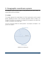
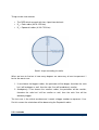
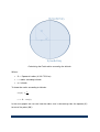
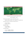
Javier Carrasco Reyes
Advisors:
Ing. Zbyněk
ěk Bureš, Ph.D.
Prof. Ing. Václav Přenosil,
P
CSc.
Department of Information Technologies
Masaryk University
LOCALIZATION OF
ENTITIES AND
CONFIGURATION OF AN
ENVIRONMENT BY
WIRELESS TECHNOLOGY
TECHNOLOG
Contents
1. Introduction ................................................................................................................. 6
2. Geographic coordinate system .................................................................................... 7
2.1. Latitude ................................................................................................................. 7
2.2. Longitude .............................................................................................................. 8
2.3. Map with parallels and meridians .......................................................................... 9
2.4. Coordinate representation..................................................................................... 9
2.4.1. Degrees minute seconds .............................................................................. 10
2.4.2. Decimal degrees ........................................................................................... 10
3. Requirements ............................................................................................................ 12
3.1. Functional requirements...................................................................................... 12
3.2. Non-functional requirements ............................................................................... 12
3.3. Technical requirements ....................................................................................... 13
3.3.1. Waterproof .................................................................................................... 13
3.3.2. Wireless ........................................................................................................ 14
3.3.2.1. Triangular from vertex mesh topology ................................................ 14
3.3.2.2. Triangular from base .......................................................................... 15
3.3.3. Buoy nodes self power supplied and energetically efficient .......................... 15
4. Material for learning and developing ......................................................................... 17
4.1. Developing material ............................................................................................ 17
4.1.1. Protoboard .................................................................................................... 17
4.1.2. Oscilloscope ................................................................................................. 18
4.2. GPS .................................................................................................................... 18
4.2.1. NMEA messages .......................................................................................... 19
Page 2
4.2.1.1. NMEA GPS messages .......................................................................... 19
4.2.1.2. NMEA PMTK message ......................................................................... 20
4.2.3. Adafruit Ultimate GPS Breakout v3 ............................................................... 22
4.3. PIC microcontrollers ............................................................................................ 22
4.3.1. Programming PIC ......................................................................................... 22
4.3.2. Learning about PIC ....................................................................................... 23
4.3.2.1. Introducing in PIC - PIC12F675 ............................................................. 23
4.3.2.1. Using UART and GPS - PIC12F1840 .................................................... 25
4.3.3. The definitely microcontroller for the project - PIC18F24K22........................ 29
4.4. IQRF ................................................................................................................... 30
4.4.1. Programming IQRF - CK-USB-04A .............................................................. 31
4.4.2. Learning about IQRF .................................................................................... 33
4.4.2.1. Using self power supplied nodes - DK-EVAL-04A ................................. 33
4.4.3. TR-52DA ....................................................................................................... 34
5. Low power consumption............................................................................................ 36
5.1. Techniques to reduce the power consumption.................................................... 36
5.2. Reducing the GPRMC message ......................................................................... 36
5.2.1. Latitude ......................................................................................................... 37
5.2.2. Longitude ...................................................................................................... 40
5.2.3. Conclusions .................................................................................................. 46
5.3. Sleep when there is nothing to do ....................................................................... 48
6. Scenario .................................................................................................................... 49
7. Specification .............................................................................................................. 52
7.1. IQRF mesh.......................................................................................................... 52
7.1.1. DFM protocol ................................................................................................ 52
Page 3
7.1.2. Coordinator ................................................................................................... 53
7.1.3. Buoy (node) .................................................................................................. 53
7.2. PIC ...................................................................................................................... 53
7.3. IQRF riders ......................................................................................................... 54
7.3.1. Coordinator ................................................................................................... 54
7.3.2. Nodes ........................................................................................................... 54
7.4. Messages protocol .............................................................................................. 54
7.4.1. Command byte ............................................................................................. 54
7.4.1.1. Set ......................................................................................................... 55
7.4.1.2. Get ......................................................................................................... 55
7.4.1.3. Mesh management ................................................................................ 55
7.4.1.4. Reserved ............................................................................................... 55
7.4.2. Buoy address byte ........................................................................................ 56
7.4.3. Data byte(s) .................................................................................................. 56
7.4.4. Commands list and their data ....................................................................... 56
7.4.4.1. LEDs getter ............................................................................................ 56
7.4.4.2. Switch OFF the LEDs ............................................................................ 57
7.4.4.3. Switch ON the LEDs .............................................................................. 57
7.4.4.4. Make the LEDs blink .............................................................................. 57
7.4.4.5. Set the duty of the LED.......................................................................... 57
7.4.4.6. Manage GPS ......................................................................................... 57
7.4.4.7. Get battery status .................................................................................. 57
7.4.5. Set/get commands summary ........................................................................ 58
8. Implementation .......................................................................................................... 59
8.1. Hardware ............................................................................................................ 59
Page 4
8.2. Software .............................................................................................................. 60
8.2.1. Working environment .................................................................................... 60
8.2.2. PIC ................................................................................................................ 60
8.2.2.1. MPLAB IDE ........................................................................................... 60
8.2.2.2. C Compiler............................................................................................. 61
8.2.2.3. ASIX UP ................................................................................................ 61
8.2.3. IQRF IDE ...................................................................................................... 62
8.3. Code IQRF .......................................................................................................... 63
8.3.1. Coordinator ................................................................................................... 63
8.3.2. Node ............................................................................................................. 64
8.3.3. Repeaters ..................................................................................................... 64
8.4. Code PIC ............................................................................................................ 64
9. Results ...................................................................................................................... 65
9.1. How it works ........................................................................................................ 65
10. Glossary .................................................................................................................. 67
11. Bibliography ............................................................................................................ 69
Page 5
1. Introduction
The implemented system consists in controlling Jetsurf races. The track is
delimited by buoys that are floating in the water, and consequently not in a fix
position.
Every buoy has a PIC microcontroller connected a GPS to know its exact
position, 2 IQRF modules to allow the communication with the rest of the system
and a battery to supply electric power the electronic components. This system
must have to take into account the low voltage as one the most important criteria,
for this purpose the sent messages will be reduce in order to use the less power
consumption possible.
As it is said, for the communication part every buoy has 2 IQRF modules: one is
used to get the position of the drivers if there are close to the buoy and the other
one works in the mesh. For the mesh, every buoy is considered a node and them
all work together in order to send the packages to the coordinator. In this way,
the coordinator can set and get information about all the buoys and about the
riders.
The coordinator can send commands in broadcast or unicast mode. These
commands can get information about the GPS (status and data), get information
about the battery and switch on/off the LEDs.
Page 6
2. Geographic coordinate system
The coordinate system can place a point in every position over the Earth surface. It is
composed by latitude and longitude.
2.1. Latitude
The latitude represents the angle between the Earth equator plane and the wanted
position regarding the Earth’s centre and which hemisphere (North or South). The
latitude 0º corresponds to the equator, the latitude 90º N corresponds to the North Pole
and 90º S corresponds to the South Pole.
The lines of constant latitude are called “parallels”, for example, the Equator is the
parallel with latitude 0º.
Latitude for a certain point
Page 7
Where:
•
A: Certain point in the Earth
•
C: Earth's centre
•
α: Latitude
2.2. Longitude
First of all, we must know what a meridian is: a line completely perpendicular to all the
parallels from North Pole to South Pole. The meridian through Greenwich (England) is
the prime meridian.
Longitude represents the angle between prime meridian and the wanted position
regarding the Earth’s centre and which part (East or West). The longitude 0º
corresponds to the meridian pole and the latitude 180º corresponds with the back part of
the prime meridian.
Latitude for a certain point
Page 8
Where:
•
A: Certain point in the Earth
•
C: Earth's centre
•
α: Longitude
2.3. Map with parallels and meridians
It is interesting to realize what latitude corresponds to the real world, because the kinds
of race that this system would not be held for example in the poles because of the cold
temperatures. We will see later how the latitude and does it affect to the system.
World map with latitudes and longitudes
[Source: Wikipedia23]
2.4. Coordinate representation
The coordinate representation use to be in the order: latitude, longitude. There are
many notations to express it, but we will focus in the more common used that contains
Page 9
the one we will work with. Those notations are degree-minute-seconds and decimal
degrees. We will use the coordinates of the city Brno (Czech Republic) as example.
2.4.1. Degrees minute seconds
The coordinates in degrees-minute-seconds system are expressed in this way:
49° 12′ 0″ N, 16° 37′ 0″ E
Like in the time system, every degree has 60 minutes, and every minute has 60
seconds.
To transform from the degrees-minutes-seconds to decimal degrees is that simple as:
= +
+
60
3600
2.4.2. Decimal degrees
The coordinates in degrees-minute-seconds system are expressed in this way:
49.2000º N, 16.6167º E
But, it could be represented like positive and negative coordinates:
•
Latitude:
o Positive → North
o Negative→ South
•
Longitude:
o Positive → East
o Negative→ West
Therefore, the example in this type of notation would be:
+49.2000º, +16.6167º
Page 10
To transform from the decimal degrees to degrees-minutes-seconds is that simple as:
= = 60 · ( = 3600 · ( − − )
−
)
60
Page 11
3. Requirements
Before starting to work, we need to know all the requirements of the system in order to
made a system that satisfies what is actually wanted. For doing this we detail all the
requirements ordered in functional, non-functional and technical.
3.1. Functional requirements
•
Create a mesh
o Bond node
o Unbond node
•
Send messages to the buoys
o Unicast + Broadcast
o Send orders
Switch on/off the LEDs and set its duty
Make sleep the nodes
Set GPS commands
o Get information
Get LEDs status
Get GPS data
Get battery status
Get riders position
3.2. Non-functional requirements
•
Documentation: The full specification is in this document.
•
Efficiency (resource consumption): The buoys require batteries and the PCB
have to take into account the power consumption.
•
Modifiability: The system has several layers, keeping the specification protocol it
is possible modify it.
Page 12
•
Extensibility: The system allows to add futures implementations, there are
reserved commands.
•
Reliability: The mesh network have repeaters which add redundant links in order
to make the system reliable.
•
Fault tolerance: The mesh network is reliable and allow the failure of some
nodes.
•
Network topology: The mesh topology has to be as tree. The reasons are the
reliability and is detailed in the point 3.3.2.
•
Response time: The system needs real-time data.
•
Scalability: The system allows from 1 to 239 nodes, more than enough to cover a
regular race.
3.3. Technical requirements
The environment will be hard because it will be the water. This point makes that
obviously the system must be waterproof.
3.3.1. Waterproof
The hardware consists in electronic must be covered and closed to prevent that the
water provoke a short-circuit.
Page 13
3.3.2. Wireless
We cannot use cables in the water because, as it is said in the previous point, the
system works in the water. For this reason it is better to work using wireless technology.
There are 2 kinds of networks: centralized or distributed. As we want to cover 1 km2,
even in the water without walls disturbing the connection is too much distance and we
would need big antennas and big batteries to supply them. Thus the best option is to
implement a mesh where the nodes create a structure with redundancy which provide
the system with reliability. All the nodes have to know how to redirect every packet to
make it get its destination that can be another node or the coordinator.
There are 2 topologies to implement the network: triangular from vertex and triangular
from base.
3.3.2.1. Triangular from vertex mesh topology
Triangular from vertex mesh topology
If the mesh has a topology like this and the critical node falls, then the full mesh would
be disabled.
Page 14
3.3.2.2. Triangular from base
Triangular from base mesh topology
In the other hand, if the mesh topology follows this criteria and one node falls, the rest of
the mesh is not affected at all. The package which were sent by a route through the
fallen node have other options to get their destination.
There are the same number of nodes but there are more path redundancy that make
the system more reliable.
3.3.3. Buoy nodes self power supplied and energetically efficient
The fact of every node is connected to the other by wireless technology make that every
must be self power supplied by its own battery. This batteries can't be very big because
of its weight (it could make the buoy sink). This forces to make the nodes energetically
efficient using techniques like making sleep what is not being used (a part, like the GPS,
or the whole buoy). Another important point to make the system more energetically
Page 15
efficient is trying to send less amount of bytes needed. For this reason all the packages
will work in binary instead of characters. There are some other techniques to reduce
some message that will be explained later.
Page 16
4. Material for learning and developing
Before learning about a complex microcontroller it is recommendable to approach the
technology learning with a simple one and going step by step from that to a complex
one.
4.1. Developing material
Before making the Printed Circuit Board is necessary to test the different devices
connected each other. For doing this we will use a Protoboard. In addition, the
connection by cables allows the fact of connecting an oscilloscope and see what if
something is being transmitted (and its times).
4.1.1. Protoboard
Protoboard is a board that gives to the user the possibility of design and change the
circuit easily. This is very interesting for the developing process, but it is interesting for
the process of learning as well. The chosen is this:
Protoboard E-CALL EIC-104
Page 17
The groups 1, 4, 5 and 8 have 2 columns each one and this columns are connected
(vertically) from the first row to the last. Every column is independent.
The groups 2, 3, 6 and 7 have 63 rows each one and this rows are connected
(horizontally). Every group has 5 rows and are independent of the other groups (for
instance: the first row is of the group 2 is not connected with the first row of the group 3.
4.1.2. Oscilloscope
An oscilloscope is an instrument to measure varying signals. In our case we will use it to
detect when the outputs are enabled or disables (for example, switching on and off a
LED) and when something is transmitted.
Oscilloscope Tektronix TDS 2012B
4.2. GPS
A GPS (Global Positioning System) is basically a device that gives the position over the
Earth's surface. The information is given in the coordinate system detailed in the point 2
(latitude and longitude).
Page 18
The GPS device we will work with is: "Adafruit Ultimate GPS Breakout - 66 channel
w/10 Hz updates - Version 3". It is able to give the information in several types of GPS
NMEA messages. It can be configured by PMTK NMEA commands messages.
4.2.1. NMEA messages
All the specification for all the NMEA GPS and NMEA PMTK messages has the same
pattern:
$CODE,DATA1,...,DATAN*CC
Where:
•
$ = Start mark of the message
•
CODE = Protocol code
•
DATA1,...,DATAN = Data of each protocol (comma-separated)
•
* = End mark for the message
•
CC = Mandatory checksum
4.2.1.1. NMEA GPS messages
All the NMEA GPS messages has the following pattern:
$GPXXX, DATA1,...,DATAN* CC
Where:
•
$ = Start mark of the message
•
GPXXX = Protocol code
•
DATA1,...,DATAN = Data of each protocol (comma-separated)
•
* = End mark for the message
•
CC = Mandatory checksum
The one we choose is our case is GPRMC. This message is by definition:
Recommended minimum specific GPS/Transit data. We will use this because, as we
said, one of the most important points is trying to reduce the power consumption
sending as less characters as possible.
Page 19
Using the same example than in the point 2, the city of Brno using GPRMC message
would be:
$GPRMC,225446,A,49.2000,N,16.6167,E,000.5,054.7,191194,020.3,E*6C
Where:
•
$ = Start mark of the message
•
GPRMC = GPRMC protocol code
•
103648 = Time of fix: 10:36:48 UTC
•
A = Indicates if the device is ready (A) or warming (V)
•
49.2000,N = Latitude 49.2000 degrees North
•
16.6167,W = Longitude 16.6167 degrees East
•
000.5 = Speed over ground (in knots)
•
054.7 = True course
•
150514 = Date of fix: 15 May 2014
•
020.3,E = Magnetic variation: 20.3 degrees East
•
* = End mark for the message
•
68 = Mandatory checksum
4.2.1.2. NMEA PMTK message
All the NMEA PMTK messages has the following pattern:
$PMTKXXX,VALUE*CC
Where:
•
$ = Start mark of the message
•
PMTK = Protocol code
•
XXX = Command code
•
VALUE = New value to set
•
* = End mark for end of the message
•
YY = Mandatory checksum
Page 20
For example, to set the baud rate, looking for in the NMEA specification we find that the
command PMTK_SET_NMEA_BAUDRATE corresponds with the code 251:
$PMTK251,38400*27
Where:
•
$ = Start mark of the message
•
PMTK = Protocol code
•
251 = Command code
•
38400 = New baud rate value to set
•
* = End mark for end of the message
•
27 = Mandatory checksum
Other example very useful related with the power consumption is to make the GPS
enter in standby mode, the command is PMTK_CMD_STANDBY_MODE and its code is
161:
$PMTK161,0*28
Where:
•
$ = Start mark of the message
•
PMTK = Protocol code
•
161 = Command code
•
0 = New value (sleep mode)
•
* = End mark for end of the message
•
28 = Mandatory checksum
Page 21
4.2.3. Adafruit Ultimate GPS Breakout v3
This is the chosen GPS device:
Adafruit Ultimate GPS Breakout - 66 channel w/10 Hz updates - Version 3
[Source: Adafruit's website11]
It provide the GPS information in all the NMEA GPS messages formats and it uses
UART (detailed in the point 4.3.2.1). It update frequency is from 1Hz to 10 Hz. Its power
consumption is very low, only 20mA, which makes this GPS device very suitable for this
project.
4.3. PIC microcontrollers
PIC is a kind of microcontrollers made by Microchip Technology Inc. They are used in a
lot of embedded systems.
4.3.1. Programming PIC
For programming and testing the codes developed for PIC will be used the Asix Presto
connected to the pins.
Page 22
ASIX PRESTO
[Source: ASIX's website6]
4.3.2. Learning about PIC
For learning we will focus in the family 12F that is one of the simplest family of PICs in
order to get the first approaching.
The learning process consists in doing miniprojects with very simple codes but it is
necessary to keep in mind that some register must to have a certain value, otherwise it
will not work even using the right code and everything is rightly connected.
4.3.2.1. Introducing in PIC - PIC12F675
This microcontroller PIC12F675 is one of the simplest in its own family. It has only 8
pins.
Page 23
Picture of the PIC12F675
[Source: Microchip's website1]
PIC12F675 pin diagram
[Source: PIC12F629/675 Data Sheet2]
This microcontroller is very simple and has 2 pins for power supply (VDD and VSS) and
the rest can be configured as input or output but the pin 4 that only can be configured as
input.
The first miniproject consists in make the LEDs blink alternatively the red and green
LEDs, its behaviour is cyclically:
1. Red ON, Green OFF
2. Red OFF, Green ON
Page 24
Circuit for the first miniproject working with PIC12F675
4.3.2.1. Using UART and GPS - PIC12F1840
This microcontroller is very similar to the previous one but it has an UART module.
Picture of the PIC12F1840
Page 25
[Source: Microchip's website1]
PIC12F1840 pin diagram
[Source: PIC12(L)F1840 Data Sheet3]
UART (Universal Asynchronous Receiver/Transmitter) is a basic module that allows
asynchronous communication. For the correct working in a communication both
modules has to work at the same bit rate. This is controlled by the register UxBRG
which controls the Baud-rate generator.
Simplified diagram of UART module
[Source: MikroElectronika's website9]
2 microcontrollers like this are used in order to send data from the one microcontroller to
the other one.
Page 26
Again, a simple miniproject to work with this microcontroller and UART bidirectional
communication with this scheme:
Draft circuit diagram for the miniproject working with PIC12F1840 using UART
The first microcontroller will roll as master and has to send the command messages
cyclically every second to the second one that roll as slave. The messages are the
following:
1. $LRON* → Switch on the red LED
2. $LGON* → Switch on the green LED
3. $LROFF* → Switch on the red LED
4. $LGOFF* → Switch on the green LED
The slave hast to obey switching on/off the led red/green according to the message
received and send an acknowledgment to the master:
•
$ACK_R* → Acknowledgment for red LED commands
•
$ACK_G* → Acknowledgment for green LED commands
Page 27
Once this miniproject is done, the next consists in master sending GPRMC to Slave
every second. Slave has to parse and store the information in its memory and then
switch the red or green LED according if the gotten information is valid, in other word, if
the GPMRC has an A or V in its validation data byte.
When it is done, then the next step is trying with the real GPS device (the one detailed
in the point 4.2.3).
Then what happened is that the LED blinked 4 times every second. Analysing with the
oscilloscope the result was this:
Analysing the signals of the miniproject circuit:
data sent by the GPS (yellow) and the LED behaviour (blue)
Page 28
Thanks to the oscilloscope was easy to realize that is like
like the message was sent like 4
times. This is because the GPS by default had configured to send the information in 4
kind of NMEA
EA GPS messages and the code only took into account the start and end
marks.
The solution was, first filtering the message detecting
detecting the GPRMC code, and then,
configuring the GPS to send only the information in GPRMC format.
4.3.3. The definitely microcontroller for the project - PIC18F24K22
And finally the PIC18F24K22 that belongs to 18F family, which is more complex than
12F but is not very hard to adapt the code we have from the code for 12F family. This
microcontroller has 16 pins, 2 UART modules and SPI interface.
Picture of the PIC18F24K22
[Source: Microchip's website1]
Page 29
PIC18F24K22 pin diagram
[Source: PIC18(L)F2X/4XK22 Data Sheet4]
With 2 UART modules we are able to connect to each buoy 2 modules IQRF (detailed in
the point 4.4) and the GPS device.
4.4. IQRF
IQRF is a wireless technology packet-oriented for low speed and low power
consumption made by Microrisc s.r.o. It works via radio frequency in low bands. It can
work either point-to-point networks and complex mesh networks. The meshes use
IQMESH protocol and IQRF provides many facilities to create a meshes in a simple
way.
This technology is very interesting for uses like telemetry and controlling as it is our
case.
Page 30
IQRF devices
[Source: IQRF's website14]
These devices are detailed later, but we need to know at least what is for each one of
this devices. The IQRF modules is actually the "Smart transceiver" (in this case TR5DA). It can be programmed using the device CK-USB-04A. The device DK-EVAL-04A
cannot program the smart transceiver but has a battery and is very useful for testing.
4.4.1. Programming IQRF - CK-USB-04A
The device CK-USB-04A does not have battery and only works connected to the
computer through a cable microUSB ↔ USB.
CK-USB-04A
[Source: IQRF's website14]
Page 31
CK-USB-04A pin diagram
[Source: CK-USB-04A User guide19]
From the software IQRF IDE we can program the device and see what is being sending
through the SPI interface. Programming the Smart receiver is very easier to resend
these message via wireless (and the same for receiving wireless messages and
forwarding them via SPI to watch what is being received). Some IQRF examples are
codes about working in this way. CK-USB-04A allows debugging as well.
It has 2 buttons: SW1 is a programmable button and SW2 is reset.
The XC3 port is the microUSB and the ports of XC1 are the pins for making connections
(similar to PIC pins).
Page 32
4.4.2. Learning about IQRF
Every IQRF device kernel is actually a PIC microcontroller with built-in operating system
which makes easier and faster the process of learning how to program it.
IQRF has many examples in its website for beginners and a quick start guide. This and
what has been learned of PIC is enough to start programming IQRF simple point-topoint networks with only 1 transmitter and 1 receiver.
IQRF has an UART module and SPI interface which allows the connection with the
microcontroller we chose.
4.4.2.1. Using self power supplied nodes - DK-EVAL-04A
DK-EVAL-04A
[Source: IQRF's website14]
Page 33
DK-EVAL-04A pin diagram
[Source: DK-EVAL-04A User guide20]
This device is very similar to the previous one (CK-USB-04A) but it has a battery and a
jumper (JP1) for switching it ON/OFF. Its XC3 port is only for charging (it cannot
program smart transceivers).
4.4.3. TR-52DA
TR-52DA
[Source: IQRF website14]
Page 34
TR-52DA block diagram
[Source: TR-52D Data Sheet21]
This is the most important part of the IQRF systems. Is what is programmed and, in our case, it
can be programmed as coordinator or node. It has a temperature sensor, a battery sensor, an
RF antenna and 2 LEDs: red and green, which is very useful for developing.
Page 35
5. Low power consumption
As we said, the low power consumption is one of the most important points of the
project.
5.1. Techniques to reduce the power consumption
The most intuitive way of reducing power consumption is switching off part or all the
modules connected to batteries in order to make it decrease. The 3 devices we have in
every buoy (PIC, IQRF and GPS) have standby mode.
Another way is trying to reducing the wireless connections because they use to spend
so much power. If we add the fact that every message has to be resent through the
mesh nodes, this makes that the nodes closer to the coordinator will work almost all the
time while the race is being held. Thus sending as less bytes as possible is one of the
priorities to reduce power consumption.
According to Amdahl's law, to get the maximum improvement in the whole system
improving a part of it. In our case, we have to focus in what is occupying the most
common message sent, and it is the coordinates (buoys and riders position), so our aim
is to reduce the GPRMC message.
5.2. Reducing the GPRMC message
We need to cover the geopositioning of some objects in a region with size 1000 x 1000
meters and try to send as less amount of characters as possible. For this reason we
need to know which part of the GPRMC message will be transmitted and which will not.
The objectives are to remove the non-necessary information and calculate how less is
needed to represent the wanted area. In the first approach the calculations will be done
in decimal to simplify the concept and then transformed and adapted to binary.
This system will work just over the sea. This fact makes the calculations more accurate
because experimental the radius will be very close to the real.
Page 36
Things to take into account:
•
The GPS which we work with has 4 precision decimals
•
Rp = Polar radius (6378.1370 km)
•
Re = Equatorial radius (6,356.7523 km)
Earth's shape according its radius
What we have to find out is how many degrees are necessary at least to represent 1
km for the worst case.
1. If we choose the biggest radius, the perimeter will be bigger, therefore the ratio
km/º will be bigger as well, then the ratio º/km will be obviously smaller.
2. Analogously, if we choose the smallest radius, the perimeter will be smaller,
therefore the ratio km/º will be smaller as well, then the ratio º/km will be
obviously bigger.
The last case is the critical one because it needs a bigger number to represent 1 km.
For this reason the calculation will be done using the Equatorial radius.
5.2.1. Latitude
Page 37
The longitude is constant for all the latitudes of the Earth as we can see in the next
image:
km/º ratio according the longitude
It makes the calculations very simple:
R = Equatorial radius (6,356.7523 km)
1 = 6,356.7523 2 · 2 · 3 = 39,940.6527 km
67,789.:;<= >?
6:9º
= 110.9463 kmBº
This means that every degree of longitude represents 110.9463 km over the Earth
surface. With only the decimal part it is possible to represent this distance (from 0.0000º
to 0.9999º we cover exactly 1º or 110.9463 km). Therefore we will need only some
digits of the decimal part to represent 1 km.
Page 38
To get how many degrees we need to cover 1 km is as simple as calculate the inverse:
1
110.9463 kmBº
= 0.0090 ºBkm
We know that we always will have fixed number of decimals: 4, because our GPS that
we are working with gives the information in the format XX.XXXXº. To avoid decimals
we will multiply by 10,000 (to simplify this process will be called “normalize degrees”
from now on and the unit will be called "normalized degrees [nº]").
10,000 º
= 90 nºBkm
0.0090 ºBkm ·
1º
Then in chars it is only necessary 2 chars to represent 1 km.
Now is time to convert the information we have to binary. The normalization makes this
process simpler because we can work with positive integers.
90D9 nºBkm = 1011010< nºBkm
We need only 7 bits to represent 1 km in the longitude. In total, with 7 bits:
2= nº = 128 nº
128 º ·
Dº
D9.999 Fº
0.0128º ·
= 0.0128º
DD9.78:6 GH
Dº
= 1.42 km
As we just saw, with 7 bits it is possible to represent until 1,42 km for longitudes.
Page 39
5.2.2. Longitude
As we just have seen, the radio km/º in the longitude is constant, in other words, no
matter which latitude are we, 1º of longitude always will be 110.9463 km.
Nevertheless, the ratio “km/º” in the longitude changes according to the latitude:
km/º ratio according the latitude
For this reason, we need to know from which latitude (until the poles) the ratio º/km
becomes 1 (1 º = 1km).
For the calculations we have to assume that Earth is a perfect sphere (as it is said
before, it will be used the equatorial radius).
Page 40
Calculating the Earth radius according the latitude
Where:
•
Re = Equatorial radius (6,356.7523 km)
•
r = radius according latitude
•
α = latitude
To know the radius according to latitude:
(I) =
JK
= JK ⋅ (I)
In the next graphic we can see how the radius size is decreasing from the equator (0º)
to one of the poles (90º).
Page 41
Earth's perimeter according the latitude
First of all, we have to find out the latitude where the ratio “km/º” reaches the value 1. If
1º = 1 km and the Earth has 360º, then logically:
360º DGH
Dº
= 360 2
When the Earth perimeter decreases until 360 km, in that point 1º = 1 km. Then we
need the radius (rc) of the Earth when its perimeter
perimeter measures 360 km:
360 2 = 2 ⋅ 3 M
=
M
360 2
2⋅3
Replacing in the equation we had:
(I) =
M
JK
Page 42
360 2
(I) = 2 ⋅ 3
JK
(I) =
(
360 2
2 ⋅ N JK
360 2
360 2
) = (
) = 89,4836º
2 ⋅ N JK
2 ⋅ N 6,356.7523 2
The latitude 89,4836º corresponds to the poles and any race will be held there because
of the cold temperatures.
Taking into account that with 1º (0º - 0.9999º) we can represent 1 km until 89,4836º,
then the next step is to find out how many chars we could send as minimum. The
applied technique consists in see how much decimetres (to avoid decimals) we can
represent according how many chars are sent and which would be the maximum
latitude that can be represented for each radius (multiplied and divided by powers of 10,
because every char can represents from 0 to 9).
As we saw in the previous section in the calculations of the longitude, the technique to
avoid decimals will be similar, but in this case we will work with decimetres (dm).
Page 43
This is the result table:
dm that can be represented according the number
of available chars (and its maximum latitude)
Maximum latitude according the number of available chars
The minimum we need to cover is 1 km = 10,000 dm. The green cells
cell means that it can
be represented and red cannot.
can . In this case the best choice would be to send 3 chars
because 84.8287º is more than enough. Sending 2 chars would be insufficient because
Page 44
this would means that the system only would work between 25,6665º N and 25,6665º S
and it is a very strong restriction (it only would work more or less between the tropics).
But to optimize even more we will work in binary, so the same methodology is repeated
to represent the maximum dm according the number of bits sent.
This is the result table:
dm that can be represented according the number
of available bits (and its maximum latitude)
Page 45
Maximum latitude according the number of available bits
5.2.3. Conclusions
First of all, working in bits we can reduce the numbers significantly and the only thing
we have to assume is multiply by 10,000 to avoid decimals (and then divide by 10,000
when the data will be treated).
To represent the latitude number we need only 7 bits, and to represent North or South
we would need another bit (N→0, S→1).
We
e can assume that all the races will be held at least in the latitudes between 0º and
76.3329º (N and S), therefore we need as a minimum 9 bits. To represent East or West
we would need another bit (E→0,
(
W→1).
The fact of send or not the North/South and East/West bits could be optional, but if a
race is held just in the equator or in the prime meridian, then the system would not work
because there would be same value for 2 different points (for example: 0.0001 N and
0.001 S, and analogously 0.0001 E and 0.0001 W) and this system must be prepared
for all the realistic latitudes and longitudes where a race could
could be held.
Page 46
Zone where the system works (green) and where not (red)
[Source: Wikipedia23] + edited
Taking the same example, Brno had this NMEA GPS message:
$GPRMC,225446,A,49.2000,N,16.6167,E,000.5,054.7,191194,020.3,E*6C
Assuming that the data is valid and not warming (character A):
•
Latitude: 49.200010,N
•
Longitude: 16.616710,E
Multiplied by 10,000:
•
Latitude: 49200010,N
•
Longitude: 16661710,E
Transformed to binary:
•
Latitude: 11110000001111000002, 0
•
Longitude: 1010001010110110012, 0
Page 47
And taking only 7 bits for latitude (+ 1 for North/South hemisphere) and 9 bits for
longitude (+ 1 for East-West hemisphere):
•
Latitude: 11000002, 0
•
Longitude: 0110110012, 0
So with this format system we need only:
(7 + 1) + (9 + 1) = 18 O
P18 O 1 OQ
R = 3 OQ
8 O
Only 3 bytes with 6 free bits to add some extra information (for example, if the data is
valid or the GPS is warming with 1 bit (A→1, V→0).
We reduced from 66 characters (66 bytes) to only 3 bytes. It is a very important
reduction and it allows to reduce critically the power consumption. In addition, this also
improves the speed of the system because the messages are send (and resend by
every node) very much faster.
5.3. Sleep when there is nothing to do
As it is said before, switch off modules connected to the batteries reduce as well the
power consumption. For doing this we have to see how to do it for every device:
Device
Adafruit GPS
PIC18F24K22
IQRF → TR
IQRF → RF IC
Make it sleep
Sending to it the command
"$PMTK161,0*28" via UART
By code: OSCCON.IDLEN=0
By code: iqrfSleep()
By code: setRFsleep ()
Wake it up
Sending to it any byte via UART
By code: OSCCON.IDLEN=1
Power OFF/ON, watchdog timeout
or on the C5 pin change
By code: setRFready()
Page 48
6. Scenario
The scenario of the races consists in buoys floating in the water in an 1000 x 1000
meters area as a maximum.
Scenario diagram
Every buoy have a PCB with a PIC, 2 IQRF modules working in 2 frequencies (1 for the
mesh where every buoy is a node and another to get the closer riders).
Page 49
Buoy devices diagram
The coordinator consists in a pc in one of the sides of the race area connected to a 2
IQRF modules: one for the mesh and another one for the riders.
Coordinator diagram
Page 50
In all of the side of the coordinator there are many repeater which are very similar to the
buoys but without GPS, and their only task is to resend the messages. They are
redundant and its use is just to make the mesh more reliable.
Repeater diagram
Page 51
7. Specification
Following the criteria of sending as less data as possible, the commands are bit-level
defined but trying to has an easy way of interpreting what kind of command is.
7.1. IQRF mesh
With all the buoys interconnected we get the IQRF mesh. The mesh is responsible of
the synchronization.
7.1.1. DFM protocol
The chosen protocol is DFM (Discovered Full Mesh). It allows up to 240 devices and
original random placement of the nodes. The way to work is the next:
1. Bond all the nodes
2. Run Discovery
•
It makes a routing backbone divided in zones according the minimum
number of hops
3. If the topology changes, run Discovery again
DFM protocol graphic
[Source: IQRF OS User's Guide17]
Page 52
In our case, once the buoys are set in their places they will stay more or less in the
same place, so the topology of the mesh will not change.
7.1.2. Coordinator
Its tasks are (mainly):
●
●
●
●
Manage the mesh
Send messages Unicast + Broadcast
Send orders and request data to/from the buoys
Receive data from the riders
7.1.3. Buoy (node)
Its tasks are (mainly):
●
●
●
●
●
Set its own address (bond) and unbond
Set power-down (standby)
Get (send) information about the battery status
Forward messages to PIC from the coordinator
Forward messages from PIC to the coordinator
7.2. PIC
The microcontroller is the kernel of the buoy. Its tasks are (mainly):
●
●
●
●
LEDs:
○ ON
○ OFF
○ Blink
○ Duty (0% - 100%)
GET
○ Data and status of the buoy's GPS
Configure GPS
Send riders' data
If data from the riders is received, this data is sent through the IQRF mesh synced according
which driver is the data from. This is only as support to the IQRF network, because in some
points of the race a rider can be very far from the coordinator.
Page 53
7.3. IQRF riders
IQRF devices set in the Jetsurfs provide the data about their position (and maybe an
extra telemetry information) using IQRF in another frequency.
7.3.1. Coordinator
Every 200 ms, get the information of each one of 5 riders (what implies that every IQRF
rider has 40 ms to send its information).
7.3.2. Nodes
The nodes of every rider and synchronized and calculates (and send) its information
during its "window time". For synchronization the parsing of the GPS message is used
(the time 0 is considered when PIC reads the GPS code GPRMC).
7.4. Messages protocol
First of all, some key characters are defined for interpreting the commands:
• N: Does not matter, either 0 or 1
• V: Value (to set)
• X: Defined later
The structure of the commands is always:
CMD ADR [PAR]
Where:
• CMD: Command (1 byte)
• ADR: Destination address (1 byte)
• PAR: Parameters [only for setters and if it is needed] (1 or several bytes)
And the return policy is 1 or several bits. The coordinator adds "OK" or "ERR" in the
firsts characters to know if the command have been correctly executed, and if it is "OK"
then information about the sender.
7.4.1. Command byte
What is wanted to do is defined by only one byte:
Page 54
X7X6 X5X4X3X2X1X0
Where:
•
X7X6: Command group (set/get/mesh)
•
X5X4X3X2X1X0: Specific command of the specified group
7.4.1.1. Set
The set commands have the following pattern:
00 XXXXXX
7.4.1.2. Get
The set commands have the following pattern:
01 XXXXXX
Get is only allowed for unicast.
7.4.1.3. Mesh management
The mesh management commands have the following pattern:
10 XXXXXX
And the available commands are:
•
X7X6 X5X4X3X2X1X0 = 10 000000: Bond
•
X7X6 X5X4X3X2X1X0 = 10 000001: Unbond
•
X7X6 X5X4X3X2X1X0 = 10 000010: Clear all the bondings
•
X7X6 X5X4X3X2X1X0 = 10 000011: Run "Discovery"
7.4.1.4. Reserved
There is a space for future implementations following this pattern:
11 XXXXXX
Page 55
7.4.2. Buoy address byte
The whole second byte sent is to specify the destination address:
X7X6X5X4X3X2X1X0
The address can be:
● 0: autobonding (only used for bonding)
● 1-239: unicast
● 255: broadcast
7.4.3. Data byte(s)
The commands that need extra information are sent after the address in one or several
bytes.
7.4.4. Commands list and their data
According to which command is sent, there will be answer or not, and the data
information that every command needs will be different.
The return policy is different for every command, but basically is the requested
information.
7.4.4.1. LEDs getter
The getter is the same for all the commands of the LED control:
•
X5X4X3X2X1X0 = 0000NN
o Get: The information about how is the LED (ON or OFF and the duty)
Returns 1 byte: X7 X6X5X4X3X2X1X0
•
X7: Status of the LEDs (0→ OFF, 1 → ON)
•
X6X5X4X3X2X1X0: Intensity (percent between 0 and 100)
Page 56
7.4.4.2. Switch OFF the LEDs
• Command X5X4X3X2X1X0 = 000000
o Set: Switch OFF the LEDs
7.4.4.3. Switch ON the LEDs
• Command X5X4X3X2X1X0 = 000001
o Set: Switch ON the LED
7.4.4.4. Make the LEDs blink
• Command X5X4X3X2X1X0 = 000010
o Set: Make the LED blinks
7.4.4.5. Set the duty of the LED
●
●
Command X5X4X3X2X1X0 = 000011
○ Set: Set the duty of the LED
Parameter: X7X6X5X4X3X2X1X0 = YYYYYYYY
○ Where YYYYYYY = % of duty to be set (from 0 to 100)
If it is greater to 100, the duty will be set to 100%
7.4.4.6. Manage GPS
The getter gives information about the current position of the buoy
•
X5X4X3X2X1X0 = 000100
o Get: The information of the buoy position
Returns: 3 bytes
o Set: Send command to the GPS
Several bytes in format NMEA PMTK
7.4.4.7. Get battery status
The getter gives information about the battery status:
•
X5X4X3X2X1X0 = 000101
o Get: The information about the battery status:
Returns: 1 byte
•
Percent about battery status (0% - 100%)
Page 57
7.4.5. Set/get commands summary
Command
Get
Set
Parameters
0000
Get status of the LED
Switch OFF the LEDs
0001
Get status of the LED
Switch ON the LEDs
0010
Get status of the LED
Make blink the LEDs
0011
Get status of the LED
Set the duty of the LEDs
Duty of the LED
0100
Get GPS information
Set GPS command
Command for the GPS
0101
Get Battery information
---
0111
---
Make buoy sleep
Page 58
8.. Implementation
The implementation of the system consists in uses this system in PCBs (Printed Circuit
Boards).
8.1. Hardware
This is the PIC microcontroller scheme inside of the PCB with all the connections.
PCB circuit scheme
This PCB is ready to be programmed and become a buoy of the system. With several
buoy we can finally generate the wanted mesh to control the Jetsurf races.
Page 59
8.2. Software
The software used in this project is specific for every device because the code is in a
very low level.
8.2.1. Working environment
The used operating system has been Windows 7 because majority of the software for
programming this devices are made for windows.
8.2.2. PIC
Programming PIC requires some software application: MPLAB to compile (and debug)
the code, a C Compiler and Asix UP to upload the binaries to the microcontroller.
8.2.2.1. MPLAB IDE
Microchip provide its own IDE for working with their microcontrollers called MPLAB IDE.
Is up to the user use another compiler, MPLAB IDE allows the user to choose another
one compiling from the same application. It provides a debugger even with simulated
UART.
Working with MPLAB IDE
Page 60
8.2.2.2. C Compiler
For the learning PICs of the family 12F was used the compiler B Knudsen Data (BNKD
from now on) CC5X. Nevertheless, for the PIC used in the buoy of the family 18F was
used the compiler BNKD CC8E.
8.2.2.3. ASIX UP
ASIX UP is an application that uses the ASIX PRESTO device to program PIC
microcontrollers. It allows to configure some parameters from its interface.
ASIX UP
Page 61
8.2.3. IQRF IDE
IQRF provides an IDE for programming and debug their devices.
Working with IQRF IDE
Debugging is not simulated, what means that is possible to analyse real scenarios. This
interfaces is very intuitive and useful, it can send and receive messages through SPI to
a IQRF device connected via microUSB.
To program the code the chosen editor was Notepad++ which is very friendly for IQRF
IDE. If an error is found during the compilation, just clicking in the line in IQRF you are
redirected to the file and line in Notepad++.
Page 62
Working with Notepad++
8.3. Code IQRF
The code of the IQRF is mainly related with the communication.
8.3.1. Coordinator
The coordinator basically treat and analyses the information. If there are wrong
commands (for example, make a get in broadcast) it just shows and error and does not
send anything in order to avoid send invalid commands. If the command is valid, then it
is send to the mesh.
Page 63
8.3.2. Node
The node receive orders and execute them. If the command is something that the own
IQRF module can do (for example, check the battery status or something related with
the mesh level) it is just done. If the node is not its task, then the command is forward to
the PIC microcontroller.
8.3.3. Repeaters
Repeaters are just a dumb version of the nodes and their only task is just to resend
forward the messages to the rest of the mesh.
8.4. Code PIC
The PIC microcontroller has to obey the orders received by the IQRF module and obey
them, and answer if it is needed. In addition, It has to store and update the information
of the GPS every time is gotten. If an information of any rider is gotten, then it has to
send it through the mesh according the fixed criteria.
Page 64
9. Results
9.1. How it works
We have one coordinator and many nodes of the network. We will assume that all the
devices are already programmed and the coordinator is connected to the computer. The
first step is bonding all the nodes to create a non-structured mesh. To do this we will
use the command bond with the address 000 in order to assign addresses sequentially
(autobonding).
The bonding string will be:
•
Command: 1000 00002 = 8016 = 12810
•
Address:
0000 00002 = 0016 = 00010
So, in the IQRF IDE we could send (both are valid and the same):
or:
It is easier to transform from binary to hexadecimal, so we will work in hexadecimal from
now on.
When the command is sent, then the LED of the coordinator will start to blink. While this
time, we have to press the button of the node which we want to bond. If everything is
done correctly we will see:
Page 65
Those lines means:
1. Welcome message
2. Autobond
3. Bond correct. Bond address = #1, node id = $409F
If an error happens, then we would see:
In this way all the nodes (and repeaters) must be bonded to make all of them part of the
mesh. Once the mesh is done, it is time to place every buoy in their place and run the
"discovery" command in order to make the topology:
•
Command: 10 0000112 = 8316 = 13110
It is done. The system is created and working. To send the rest of commands would be
in the same way.
If we press the IQRF's button during 2 seconds it will sleep. If this button is pressed
during 5 seconds, it will unbond.
Page 66
10. Glossary
Baud rate: unit used for symbol (symbols per second) or modulation rate (pulses
per second. In our case, we work with digital systems, so: 1 S = 1 OB Jetsurf: is a high-tech motorized surf-board made by MSR Engines. It can reach
speeds about 50 km/h.
normalized degree [nº]: corresponds to the degrees which represents the latitude
and longitude multiplied by 10,000 in order to avoid decimals. In this way, the
information is sent in binary as a positive integer.
PIC microcontroller: Peripheral Interface Controller. It is a small computer on a
single integrated chip made by Microchip Technology Inc
GPS: (Global Positioning System) Is basically a device that gives the position over
the Earth's surface.
IQRF module: Intelligent Radio Frequency. A programmable radio frequency
transceiver with UART and SPI interfaces.
PCB (Printed Circuit Board): Board with the circuit printed on itself. It is used as
base for physically supporting and wiring surface-mounted and socketed
components.
NMEA: National Marine Electronics Association. A organization which develops
electrical and data specifications for marine electronics.
PMTK NMEA: Packet MediaTek/ETEK. Standard message protocol to configure
some GPS devices.
GPS NMEA: Standard message protocol of GPS notation.
GPRMC: Recommended minimum specific GPS/Transit data. One of the GPS
MNEA messages protocol.
Page 67
UART: Universal Asynchronous Receiver/Transmitter. Basic module that allows
asynchronous communication. It has its own protocol.
SPI interface: Serial Peripheral Interface. It is a bus that allows synchronous serial
communication interface. Is commonly used for short distance communication,
primarily in embedded systems.
IDE: Integrated development environment. It is a software application for developing
(programming, debugging and compiling) source code that provides comprehensive
facilities to the user.
Page 68
11. Bibliography
[1]
Microchip Technology Inc. - Website
[http://www.microchip.com]
[2]
Microchip Technology Inc. - PIC12F629/675 Data Sheet
[3]
Microchip Technology Inc. - PIC12(L)F1840 Data Sheet
[4]
Microchip Technology Inc. - PIC18(L)F2X/4XK22 Data Sheet
[5]
MPLAB® IDE - Quick start guide
[6]
ASIX s.r.o. - Website
[http://www.asix.net]
[7]
B Knudsen Data - CC5X User's Manual
[8]
B Knudsen Data - CC8E User's Manual
[9]
MikroElectronika - Website
[http://www.mikroe.com]
[10]
MikroElectronika - Website
[http://www.mikroe.com]
[11]
Adafruit® - Website
[http://www.adafruit.com]
[12]
Adafruit® - Adafruit Ultimate GPS Guide
[13]
GlobalTop Technology Inc. - PMTK command packet (Rev. A08)
[14]
Microrisc s.r.o. - IQRF Website
[http://www.iqrf.org]
Page 69
[15]
Microrisc s.r.o. - IQRF Quick Start Guide
[16]
Microrisc s.r.o. - IQRF OS User's Manual (Version 3.04D for TR-5xD)
[17]
Microrisc s.r.o. - IQRF OS User's Guide (Version 3.04D for TR-5xD)
[18]
Microrisc s.r.o. - IQRF OS Reference Guide (Version 3.04D for TR-5xD)
[19]
Microrisc s.r.o. - CK-USB-04 IQRF Programmer and Debugger User's Guide (Firmware v1.00)
[20]
Microrisc s.r.o. - DK-EVAL-04A IQRF development kit - User's Guide
[21]
Microrisc s.r.o. - TR-52D Data Sheet
[22]
Microrisc s.r.o. - SPI Implementation in IQRF TR modules
[23]
Wikimedia Foundation, Inc - Wikipedia Website
[http://www.wikipedia.org]
Page 70