1
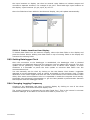
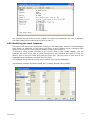
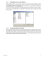
Campbell Based Multi-Channel Data Logger User Manual Man158 2.1.1. 06/08/2014 Final David Farnham Chris Rasmussen Chris Rasmussen Manual No. Revision Date Status Originator Checked Authorised for Issue User Manual 1 Contents Section 1 : Foreword ....................................................................................................... 3 Section 2 : Introduction .................................................................................................. 4 2.01 2.02 General description .............................................................................................. 4 Overview of operation ........................................................................................... 4 Section 3 : Installation of logger ..................................................................................... 5 Section 4 : Installation of software ................................................................................. 6 4.01 4.01.1 4.01.2 4.02 4.03 LoggerNet Installation .......................................................................................... 6 CD-ROM Installation ............................................................................................. 6 Upgrade Notes ..................................................................................................... 6 Copy Logger Programs from Soil Floppy disc ............................................................ 6 Configure LoggerNet ............................................................................................. 6 Section 5 : Operation of logger ....................................................................................... 7 5.01 Programming the Datalogger ................................................................................. 8 5.01.1 Sending Program to Datalogger ............................................................................. 8 5.02 Data Displays ...................................................................................................... 9 5.02.1 Numeric Display Screen ........................................................................................ 9 5.02.1.1 Adding Locations to Display ................................................................................ 9 5.02.1.2 Delete Locations from Display ........................................................................... 10 5.03 Setting Datalogger Clock ..................................................................................... 10 5.04 Changing Logging Frequency ............................................................................... 10 5.05 Retrieve Data .................................................................................................... 11 5.05.1 Collect Now/ Stop Collection ................................................................................ 11 5.05.2 Data Format ...................................................................................................... 11 Section 6 : 6.01 6.02 Configuring the System ............................................................................... 12 Modifying the datalogger Program ........................................................................ 12 Modifying the input locations ............................................................................... 13 Section 7 : Getting Help for LoggerNet Applications ...................................................... 14 APPENDICES ................................................................................................................... 15 A. A.1 A.1.1 A.1.2 A.2 A.2.1 A.2.2 A.2.2.1 A.2.2.2 A.2.2.3 A.2.2.4 A.2.3 A.2.4 A.2.5 A.2.6 A.3 A.3.1 A.3.2 A.4 User Manual LoggerNet Set-Up ............................................................................................ 16 Setting Up a Datalogger Network ......................................................................... 16 Adding Devices to the Network ............................................................................ 17 Renaming Network Devices ................................................................................. 17 Device Configuration Settings .............................................................................. 18 Serial Port ......................................................................................................... 18 Datalogger ........................................................................................................ 18 Hardware Tab................................................................................................... 19 Schedule Tab ................................................................................................... 19 Final Storage Area 1 and 2 (Array-based dataloggers only) .................................... 20 Clock Check/Set Tab ......................................................................................... 21 MD9 Base.......................................................................................................... 21 MD9 Remote...................................................................................................... 21 PhoneBase ........................................................................................................ 22 PhoneRemote .................................................................................................... 22 Setting Up Scheduled Data Collection ................................................................... 22 Data Collection Scheduling Considerations ............................................................ 22 Setting Up Scheduled Data Collection ................................................................... 23 Retrieving Datalogger Program ............................................................................ 23 2 Section 1 : Foreword Soil Instruments multi-channel logger, as with all our readout equipment, has been designed to operate consistently in a construction site environment and is therefore relatively robust. However, it is essential that the equipment covered by this manual is both operated and maintained by competent and suitably qualified personnel. They must READ AND UNDERSTAND the procedures outlined in this manual before attempting the installation or operation of the equipment on site. Itmsoil Ltd will not accept for repair under guarantee, instruments that have been neglected or mishandled in any way. User Manual 3 Section 2 : Introduction 2.01 General description The data logging system is based around a Campbell Scientific CR800 or CR1000, and a number of peripheral devices. These include various types of interface multiplexers and either a power supply and small backup battery or a larger replaceable re-chargeable battery. It will also include some form of serial communication interface which will again vary depending upon the specification. All the above will be mounted in an IP66 enclosure. Although the loggers can be supplied in many variants to suit specific requirements the basic operation procedure of all units is the same. 2.02 Overview of operation This section of the manual aims to provide the user with a general understanding of how to operate the data logger. More detailed explanations will be found later in the manual. The logger is controlled using a PC. The program LoggerNet is required for this. This is used to communicate with the logger. Once the logger is installed and the sensors are connected, connect the computer to the logger via either the RS232 port or a modem and then run the LoggerNet program. Using LoggerNet send the supplied datalogger program to the logger. The logger is now running the program that was downloaded and will continue to run without the computer connected. To download stored data form the logger reconnect the computer and run LoggerNet. This has a download facility which allows the user to download data from the logger and store it on the computer in a comma delineated ASCII file. User Manual 4 Section 3 : Installation of logger The logger must be securely fastened to a wall or similar using the four brackets and bolts provided. Care should be taken when selecting the mounting position to ensure that enough room is left under the cabinet to allow for access of the transducer connection cables. If the logger is a mains unit connect the power supply to the three way connector mounted inside the logger enclosure. This is clearly marked “Mains Input” and also indicates which are the live, neutral and earth connections. The sensors to be monitored can now be connected. The exact connection of the sensors will vary depending upon the type of sensor to be used. However since all loggers are built to meet the customers requirements all the multiplexers will be clearly labelled with their appropriate channel number and connection details. Once all the sensors are connected the logger is now ready for use. User Manual 5 Section 4 : Installation of software The software comprises of two parts: Communication Software – LoggerNet Data logger program 4.01 LoggerNet Installation 4.01.1 CD-ROM Installation The following instructions assume that drive D: is a CD-ROM drive on the computer from which the software is being installed. If the drive letter is different, substitute the appropriate drive letter. Put the installation CD in the CD-ROM drive. The install application should come up automatically. If so skip to step 3. If the install does not start, then from the Windows Start menu, select Start | Run. Type D:\Disk1\Setup.exe in the Open field or use the Browse button to access the CD-ROM drive and select the set-up executable in the Disk1 folder. This activates the LoggerNet Installation Utility. Follow the prompts on the screen to complete the installation. Items are added to your computer’s Start menu under Programs | LoggerNet that start the Toolbar and some other selected utilities. If the default directories are used, LoggerNet executable files and help files are placed in the C:\Program Files\CampbellSci\LoggerNet directory. The directory C:\CampbellSci\LoggerNet is a working directory and contains the user’s programs and data files, along with files maintained by LoggerNet such as the binary data cache and configuration files. 4.01.2 Upgrade Notes If you are upgrading from an installation of Campbell PC208W version 3.0 or greater, you may want to convert your current network description from PC208W format to the LoggerNet format. Please refer to the full LoggerNet Manual for details. 4.02 Copy Logger Programs from Soil Floppy disc Insert the Soil datalogger program disc in the PC. Copy the contents of the disc into the working directory C:\CampbellSci\LoggerNet. 4.03 Configure LoggerNet LoggerNet once installed will need configuring for the computer and communication method being used. For full details see Appendix A. User Manual 6 Section 5 : Operation of logger Throughout this manual the CR800 is specified, the operations apply equally to the CR1000 data logger. Start LoggerNet; double click the icon. You can also go to the start menu of the computer and under Programs | LoggerNet select LoggerNet. This will bring up the Toolbar, as shown below, and start the server. Select the connect icon and select the logger from the station list on the left hand side. If none are shown then LoggerNet has not been configured, configure the system first (see Appendix A) then retry. When you click on the Connect button the animated graphic will indicate the connection state. It will show that LoggerNet is trying to establish the connection; the two connectors join together when the connection is made. You can also connect to the datalogger by double clicking on the datalogger name or selecting Connect from the File menu. User Manual 7 Once the connection to the datalogger is established, the connect button will display the Disconnect option, and the logger clock will be displayed on the right hand side (see below). The datalogger clock is checked continuously and displayed along with the computer clock as updates are receive. The first time the logger is used it is necessary to program the logger. The CR10X has a battery back-up which retains the logger program and clock so once programmed the program will remain even if power is removed. 5.01 Programming the Datalogger The Program section on the Connect screen is used to send (or retrieve) datalogger programs from dataloggers in the network. The logging program will be sent with the datalogger on a separate disc. The program will be set up for your system, however certain parameters may require changing (see section 4.02.2). Associate the Program. To send a program first associate the program with the logger. Select Edit | Associate program, and using the file browser select the program provided, the program will be in the folder ‘C:\Campbellsci\LoggerNet’. The program will have the extension DLD. 5.01.1 Sending Program to Datalogger To send a program click on the Send button. A standard file select dialog box will come up so you can choose the file to send. The Files of Type selector at the bottom of the dialog filters the displayed files showing only Edlog files (*.dld). After selecting the datalogger program provided a file warning will appear to remind you that data may be lost when the new program is sent. If there is any data in the datalogger that has not been collected, click Cancel to stop the program send, and collect the needed data. If OK is selected at the warning, the progress bar will come up with the program transfer progress. Once the program has been sent, the text changes to Compiling Program. When the datalogger finishes compiling the program the progress box will close. Once the logger is programmed it will read all enabled tables and then default to its normal reading interval (see section 5.03). User Manual 8 5.02 Data Displays There are three Numeric Display screens and three Graphical Display screens. Each screen is launched as a separate window that can be moved or resized as needed. The display screens are not minimised if the Connect screen is minimized but they can be minimized independently. 5.02.1 Numeric Display Screen Data values collected from the datalogger can be displayed in numerical format on the Numeric Display. Up to three Numerical Display screens can be active. The settings and selected data values are retained as part of the display settings even when the display or Connect screens are closed. The settings for each datalogger are saved independently so a different datalogger will have different settings. Clicking on one of the three numbered boxes next to the Numerical display area will bring up a Numerical Display screen. An example of one of these screens is shown below. If a Numerical Display screen is already active but hidden behind other windows, clicking on its number will bring it to the front. 5.02.1.1 Adding Locations to Display When first opened the Numeric Display is initially blank; the fields to be displayed must be selected. Press the Add button to bring up the Available Fields dialog box that lists the data fields for the available datalogger tables or final storage arrays. Selecting a table name or final storage array ID will bring up a list of data fields in the right hand window. Select the fields to add by clicking on the data field names. Multiple data fields can be selected by holding down the Shift or Ctrl key while clicking additional names. An entire table or array can be selected by clicking on the table name. The selected data fields can be added to the display either by clicking on the Paste button to enter them on the display starting at the selected cell, or dragging the selected fields to the display cells. Up to sixty data fields can be displayed simultaneously. The Available Fields dialog can be kept in front of other windows by clicking the Stay on Top checkbox. For array-based dataloggers that have an associated datalogger program, the final storage labels and input locations names are available to select and add to the display. If the datalogger doesn’t have an associated file, the input locations can still be displayed by clicking on the Select Input Locations button at the bottom of the screen. The numbers of User Manual 9 the input locations to display can then be entered using dashes to indicate ranges and commas to separate numbers. For example 2-4,6,14-17 would add eight input locations to the display: input locations 2,3,4,6,14,15,16, and 17. Once the fields have been added to the Numeric Display, they will update automatically. 5.02.1.2 Delete Locations from Display To delete data fields from the Numeric Display, select the data fields on the display and press the Delete button. Adding new data fields on top of existing fields in the display will overwrite the existing fields. 5.03 Setting Datalogger Clock Once the connection to the datalogger is established, the datalogger clock is checked continuously and displayed along with the computer clock as updates are received. The clock update can be paused by clicking the checkbox next to Pause Clock Update. In some situations it is desirable to pause the clock update to minimize data traffic over the communications link. You can manually set the clock by clicking on the Set Station Clock button. LoggerNet attempts to set the datalogger clock as closely as possible to the computer clock. A slight difference in the clocks might exist after the clock is set because of the communications time delay. Over some communication links it is impossible to match the computer clock exactly. LoggerNet uses advanced compensation to get the best possible synchronization between the computer and the datalogger clocks. 5.04 Changing Logging Frequency Connect to the datalogger and open a numeric display by clicking on one of the three numbered boxes next to the Numerical display area. The reading frequency is indicated by the label ‘Read_Intv’. This is the interval in minutes between readings. If this label is not shown then add it ( see 4.05.1.1). User Manual 10 The value shown is the interval in minutes between readings. The above example shows a logging frequency of 6 hours (360 minutes). If a datalogger is to read the sensors connected every hour this would be set to 60, valid inputs are 1 (1 minute) to 1440 (1 day). To change the value double click on the current value, this will highlight the value blue (with a yellow background) type the new value and press the enter key. The new value will now be shown. This method of changing a locations value can be used to change the values of the user settable parameters. NOTE The values can only be changed when connected to the datalogger. 5.05 Retrieve Data The Data Collection section of the Connect screen allows you to control some aspects of collecting data from the datalogger. You can force a scheduled collection to occur or initiate a custom data collection. This is also where you have access to view and set ports and flags. 5.05.1 Collect Now/ Stop Collection The Collect Now function is the equivalent of doing a scheduled data collection for the datalogger without waiting for the scheduled time. Clicking on the Collect Now button will initiate a call to the datalogger and any available data will be collected and stored as specified on the Set-up screen. Once you have started data collection with Collect Now, you can stop it by clicking on the Stop button or the Cancel button on the animated screen. This might be necessary if you started a data collection that is bringing in more data than you really wanted, especially over a slow communications link. 5.05.2 Data Format Data stored on the datalogger is normally raw data and will require processing on a computer. The data can be processed using Itmsoil I-Site software or imported into a spreadsheet program. The data file created is an ASCII file which has comma delimiters. Example: 161,2004,233.0,1200,4.3442,4.8684,3.9739,6.5825,5.3266,12.3,22.4 161,2004,233.0,1300,4.3442,4.8675,3.9739,6.5825,5.3262,12.3,22.3 161,2004,233.0,1400,4.3442,4.8681,3.9739,6.5825,5.3265,12.2,22.4 The columns in the above example contain the following: Logger ID, Year, Day of Year, Time, Sensor1, Sensor2, Sensor3, Sensor4, Sensor5, Battery, Temperature The format for each logger will depend on the individual system configuration. User Manual 11 Section 6 : Configuring the System There are two methods of modifying the configuration of the datalogger, namely changing the program or modifying input locations. 6.01 Modifying the datalogger Program THIS OPTION SHOULD ONLY BE USED BY COMPETENT PERSONS Start LoggerNet double click the icon that was placed on your desktop. You can also go to the start menu of the computer and under Programs | LoggerNet select LoggerNet. This will bring up the Toolbar, as shown below, and start the server. Select the Edlog icon. This will open the program editing software. Select File | Open and select the program provided with the system. In the following Example the program is called ‘XY TABLE V3.0.dld’. When the file opens it is shown as below. User Manual 12 Any changes are not saved until the program is saved and compiled by the user, if mistakes are made close the file without saving and re-open it. 6.02 Modifying the input locations This option will change the parameters currently in the datalogger, however if the datalogger loses power on powering up the values will return to their default values. Changing input locations is carried out in the numeric display screens (see section 5). To change a value, double left click on the current value in the numeric display. This will highlight the value blue, with a yellow background, this indicates the value is ready for editing, type in the new value and press the enter key. The new value is now sent to the datalogger and the display will show the new value. This method can be used to change any locations value on the datalogger. The following example shows the Read_Intv (reading interval) being edited. User Manual 13 Section 7 : Getting Help for LoggerNet Applications Each screen has an on-line help system. On-line help can be accessed by pressing the F1 key or by selecting Help from the application's menu. User Manual 14 APPENDICES User Manual 15 A. LoggerNet Set-Up The Set-up Screen provides a way to create and maintain a network of dataloggers. The datalogger network map shows all of the devices and communications links to reach the datalogger stations. The settings for all of the devices are displayed and can be modified on the configuration tabs. Start LoggerNet double click the icon that was placed on your desktop. You can also go to the start menu of the computer and under Programs | LoggerNet select LoggerNet. This will bring up the Toolbar, as shown below, and start the server. A.1 Setting Up a Datalogger Network The Set-up Screen is used to configure your datalogger network, define the communications link that exists between the computer and the datalogger, and set up the data collection schedule. The following are viable datalogger communications methods for the LoggerNet software: Direct Connect – Simple serial communications typically on demand and close to the computer, or where devices such as an SC32A, short haul modems or RF400 spread spectrum radios are used in a configuration that requires no dialling or addressing to appear “ transparent” . Phone Modem – Connection from a phone modem at the computer to a datalogger attached to a remote phone modem. Cell phone communication is also supported. Multi-drop Networked Direct Connect – Direct connection over dedicated cables. Clicking the Set-up button on the LoggerNet toolbar will bring up the Set-up Screen. The screen is divided into two parts: the device map (left side of the screen) and the set up tabs (right side of the screen). User Manual 16 A.1.1 Adding Devices to the Network Begin adding devices to the device map in the order that they appear in your communications link. Let's assume that your server computer is connected to the datalogger via a telephone modem. You would first add a ComPort, then the telephone modem, the remote phone modem, and the datalogger. To add a ComPort to the network map either right click in the blank area of the network map, click on the Add Root button, or choose Edit | Add Root. Once the ComPort is in place you can click on the Add button or choose Edit | Add from the menu to bring up the Add Device window. A.1.2 Renaming Network Devices The names of all of the devices can be changed as desired. Rename a device by selecting the device and either clicking again with the left mouse button on the selected device, clicking the Rename Device button, or going to the menu item Edit | Rename. The name of the selected device will change to a text edit box and the new device name can be entered. Valid names consist of letters, numbers and the underscore (_). The device name must be unique in the network and the first character must be a letter. User Manual 17 A.2 Device Configuration Settings When you highlight any device on the network shown on the left side of the Set-up Screen, configuration tabs appear on the right side with the relevant settings. These settings are different for different devices and are described in detail below. A.2.1 Serial Port The serial port has only a Hardware tab to configure. Communications Enabled - Before communications can take place, all devices in the communications chain must be enabled. The default setting for this check box is Enabled. Call-back Enabled - Enabling call-back tells LoggerNet to watch for a call-back from the datalogger on this port. If there is a phone modem attached it will be set to accept incoming calls. ComPort Connection - This field designates the communications port through which you will be connecting to the datalogger. Select the arrow to the right of the field with a mouse to display a list containing Com 1 through Com 12. Extra Response Time - If extra response time is needed, it is typically set to 1 or 2 seconds. A.2.2 Datalogger The above figure shows a CR800 called ‘XYTable’ connected directly to ComPort 1, and another CR800 connected via a modem to the computers modem which is on ComPort 3. User Manual 18 A.2.2.1 Hardware Tab Communications Enabled - Before communication can take place, all devices in the chain must be enabled. When this box is selected, the datalogger is enabled for communication. Maximum Time On-line - A time limit can be set for the length of time LoggerNet will stay connected to the datalogger on any scheduled call. Maximum Packet Size - Data is transferred in "chunks" called packets. For most devices the default value is 2048 byes. Extra Response Time - In this field, specify the additional time that LoggerNet should delay before breaking the communications link if there is no response from the datalogger. Set to 5 seconds. Additional time may be needed in instances where the communications link is noisy or network traffic is heavy. Maximum Baud Rate - Select the arrow to the right of this field to choose a maximum baud rate for communication with this datalogger. Set to 9600. Security Code - A datalogger can have a security code to restrict access to the datalogger. Call-back ID - The call-back ID is sent by the datalogger to identify itself when contacting the host computer. A.2.2.2 Schedule Tab The Schedule tab defines when LoggerNet will automatically check the datalogger for new data. Scheduled Collection Enabled - This check box activates the data collection schedule defined on this tab. No data will be automatically collected if the schedule is disabled. Apply to Other Stations - This button allows the schedule set-up for this datalogger to be copied to other stations in the network. Clicking the button brings up a window that lists all of the dataloggers in the network. You can select one or more dataloggers and then press OK to use the entered schedule. To select more than one datalogger, hold down the Ctrl key while clicking on the dataloggers to select. Base Date - The base date field is used to define the first date for scheduled data retrieval. If the date entered in this field has already passed, a data collection attempt will be made when the schedule is enabled and applied. Base Time - This field is used to define the first time for scheduled data retrieval. As with the Base Date field, if the time has already passed, a data collection attempt will be made when communication when the schedule is enabled and applied. This setting is also used with the Collection Interval to determine the time data collection will be done. NOTE Unlike PC208W, entering a zero for any of the intervals below will cause LoggerNet to try and collect as fast as possible. Collection Interval - This is the interval at which the datalogger will be checked for new data. If this interval is set at 1 hour, new data will be collected from the datalogger every hour. Example: If the Base Date and Time are 1/1/99, 12:15 p.m., with an interval of one hour, data collection attempts will be made at 15 minutes past the hour, each hour. User Manual 19 Primary Retry Interval - If a data collection attempt is made but fails, you can specify an interval on which another attempt will be made. This primary retry interval starts at the time of failure, not on the original calling time and interval. “ Failures” may be caused by busy phone lines, noisy RF environments, low batteries, damaged hardware, etc. Number of Primary Retries - The number entered into this field is the number of times the server will attempt to contact the datalogger on the Primary Retry Interval. If all the collection attempts fail, then the server will commence calling on the Secondary Retry Interval if it is enabled. Secondary Retry Interval - If the secondary retry interval box is checked, the specified interval is a calling interval that will be followed if all Primary Retries fail. Data collection attempts will continue on the Secondary Interval until a data collection attempt is successful, at which time, all retry statistics are reset. The Secondary Retry Interval is based on the initial date and time settings, not the time of the last failure. If the box is not checked the collection schedule will return to the normal collection schedule and continue through just normal and primary collection schedules until communications are restored. Typical use is to set the Primary Retries fairly close together, and the Secondary Retry at a longer interval. For instance, if you are calling on an hourly basis, the Primary Retries might be set to three tries, spaced five minutes apart. The Secondary Interval then might be set at 2 hours. Collect Ports and Flags - If this box is checked, the current state of the ports and flags is collected and stored in LoggerNet’s internal data cache. This allows functions such as the numeric display and view ports and flags to get updated data with scheduled data collection. A.2.2.3 Final Storage Area 1 and 2 (Array-based dataloggers only) When the datalogger program stores data, the data arrays are stored in a final storage area. Some dataloggers, such as the CR10X, have two final storage areas while others, such as the 21X, have only one. This tab is used to define the output filename and location, the data file format and other output options for the data stored in the final storage area. Enabled for Collection - The specified final storage area will be included in the collected data if this box is checked. Output File Name - This is the name and directory path for the output file where the final storage data will be saved after being collected from the datalogger. Use Default File Name - checking this box will set the collected data file name to the default value, which consists of the name of the station and number of the final storage area. File Output Option - This option allows you to choose whether new data collected from the station is appended to the data file, overwrites the old data in the data file, or is not stored to a data file. The default option is to append to the data file so the old data is not lost. User Manual Output Format - ASCII, Comma separated writes data to the file in ASCII text format one record per line with commas between the data values. This file can be opened in LoggerNet View, a text editor, or brought into a spreadsheet application. Collect Mode - The collect mode allows you to choose how much data to collect when getting data from the datalogger. Data Logged Since Last Call - When LoggerNet calls the datalogger to collect data, it will try to get all of the data stored by the datalogger since the previous call. If this is the first call to a datalogger there might be a lot of historical data stored. Most Recently Logged Arrays - This option is used when you are most interested in only the most recently stored data. When this option is selected you can specify how 20 many arrays back from the most recent array should be included when data is collected from the datalogger. A.2.2.4 Clock Check/Set Tab Automated Clock Check Enabled - Enable this to compare the datalogger’s clock to the server PC’s clock based on the schedule defined by the other parameters on this tab. If the datalogger's time differs from the server's time by more than a specified amount, the datalogger's clock will be set to the server’s time. Time Zone Offset - A value can be entered into this field to set an offset for the datalogger's clock from the server's clock. Positive values set the logger clock as if it were in a more eastern time zone. This may be useful if the server and the datalogger are in different time zones. Initial Date - The initial date field is used to define the date on which the first clock check will occur. If the date entered in this field has already passed, the datalogger's clock will be checked at the next scheduled data collection. Initial Time - This field is used to define the time at which the first clock check will occur. As with the Initial Date field, if the time has already passed, the clock will be checked at the next scheduled data collection. Interval - The interval at which a clock check should be performed is specified in the Interval field. If this interval is set at 24 hours, the datalogger's clock will be checked daily, based on the initial date and time. Allowed Clock Deviation - The Allowed Clock Deviation field is used to specify the number of seconds the datalogger's clock can differ from the server's before the server resets the datalogger's clock. NOTE A.2.3 The Allowed Clock Deviation setting will prevent a manual clock set from being carried out if the difference between the datalogger's and server's clocks is less than the specified deviation. MD9 Base The MD9 base modem has only a Hardware tab. NOTE LoggerNet assumes an MD9 base modem address of 255. Therefore, the MD9 base modem must have the hardware switch ID set to 255 for communication to work. Communications Enabled - Before communications can take place, all devices in the chain must have the Communications Enabled box checked. When this box is selected, communication to the MD9 base is enabled. A.2.4 MD9 Remote The MD9 remote is the MD9 modem device that is connected to the datalogger at the field site. It has a Hardware tab only. Communications Enabled - Before communications can take place, all devices in the chain must have the Communications Enabled box checked. When this box is selected, communications to the MD9 modem are enabled. Address - The hardware for each MD9 modem is configured for a certain address using internal hardware switches. This address acts as an identification for the device in an MD9 network. Each MD9 modem in the network must have a unique address; this number is entered in the Address field. User Manual 21 A.2.5 PhoneBase The PhoneBase is a telephone modem connected to one of the server's ComPorts to provide access to other devices in the datalogger network. The telephone modem has only the Hardware tab. This device must be properly installed and configured in the operating system to use one of the computer’s ComPorts before it can be used by LoggerNet. Communications Enabled - Before communications can take place, all devices in the chain must have the Communications Enabled box checked. When this box is selected, communications to the phone modem are enabled. Modem Type - Use the drop down list box to select the type of modem that is attached to the server computer's communications port. In most instances, the <default modem> should work. Edit Modem Database - The modem connected to the server computer may not be listed in the database, or the user may desire to change the modem configurations. When the Edit Modem Database button is selected, the reset and initialisation strings for the selected modem are displayed. You can change these settings or add a custom modem to the list. If you change the settings for one of the standard modems you will have to save it to a new name to use it. The only modems that can be deleted from the list are modems that have been added by the user. Extra Response Time - In this field, specify the additional time that the LoggerNet server should delay before breaking the communications link if there is no response from the phone modem. Additional time may be needed in instances where the communications link is noisy or network traffic is heavy. NOTE A.2.6 LoggerNet waits a certain amount of time for a response from each device in a communications path. The extra response times defined for the communications link are cumulative. Therefore, the amount of time spent waiting for a device to respond is the sum of all Extra Response Times defined, plus the default response time for each device in the link. Add the minimum time necessary since very long response times can delay other scheduled events while waiting for a device that is not responding. PhoneRemote The Hardware tab of the remote phone modem is used to set up the dialling string for the remote device attached to it. The hardware tab has the following controls: Communications Enabled - Before communication can take place, all devices in the chain must have the Communications Enabled box checked. When this box is selected, communication to the remote phone modem is enabled. Phone Number/Delay Field - This field is used to enter the telephone numbers or dialling strings for the remote modem. To add a number to the list simply click on the <add phone number> field and type in the number. Spaces, dashes and parentheses are usually ignored by the modem. To remove or change a number, highlight the number and delete or click on the number and use backspace. A.3 Setting Up Scheduled Data Collection A.3.1 User Manual Data Collection Scheduling Considerations 22 As the data is collected from the dataloggers it is placed in data files according to the settings specified for that station. The data is also kept in data storage areas by LoggerNet for use by the display screens such as the Numeric Display and Graph screens. For data to be collected it has to be selected for collection on the Data File or Final Storage tab in the Set-up screen for each datalogger (Section 3.02.2). If the tables or final storage are not selected for collection, no data will be stored or displayed on the display screens. A.3.2 Setting Up Scheduled Data Collection The data to be collected and the output file locations and format are specified on the datalogger's Data File or Final Storage tab (Section 3.02.2.3). The Schedule tab (refer to Section 3.02.2.2) is used to define the interval on which the LoggerNet server will check the datalogger for new data. If new data exists, it will be stored in the data files and the LoggerNet internal storage, which is accessible to the Numeric Display and Graph. To set up a data collection schedule for a datalogger, first ensure that your device map has been configured with all of the devices listed as they actually exist. Next, determine which final storage areas should be collected from the datalogger each time a data collection attempt is made. You should check the directory path and the data file options to make sure the files are where you want them and in the right format. The data collection schedule should be set up next. Set the initial date and time to when you would like the first data collection attempt to occur and set the interval at which subsequent data collection attempts should occur. Make sure that communications are enabled for all devices in the communications path, and that scheduled collection is enabled. If the initial date and time is set to a time that has already passed, data collection will normally begin immediately. A.4 Retrieving Datalogger Program The program running in the datalogger can be retrieved and saved to a file by connecting to the datalogger and clicking on the Retrieve button. You will be prompted for a name and directory to store the retrieved file. Bell Lane, Uckfield, East Sussex t: +44 (0) 1825 765044 e: [email protected] TN22 1QL United Kingdom f: +44 (0) 1825 744398 w: www.itmsoil.com Soil Instruments Ltd. Registered in England. Number: 07960087. Registered Office: 5th Floor, 24 Old Bond Street, London, W1S 4AW User Manual 23