1
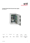
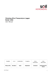
Pneumatic Piezometer User Manual Man014 3.0.2 13/03/2013 Chris Spalton Chris Rasmussen Chris Rasmussen Manual No. Revision Date Originator Checked Authorised for Issue User Manual 1 Contents Section 1 : Introduction ............................................................................................................... 3 Section 2 : General Information ................................................................................................... 4 Section 3 : Installation Techniques .............................................................................................. 5 3.01 3.02 3.03 3.04 Borehole Installation with Sand Cell ................................................................................. 5 Push-In Installation ....................................................................................................... 7 Up-Hole Installation ....................................................................................................... 8 Trenching of Tubing ....................................................................................................... 8 Section 4 : Reading Technique ................................................................................................... 10 4.01 4.02 4.03 4.04 Section 5 : 5.01 5.02 5.03 5.04 User Manual Principle of Operation of Pneumatic Transducers .............................................................. Use of the Gauge Push-Button Pneumatic Readout Unit .................................................... Use of the Gauge Two-Valve Pneumatic Readout Unit ...................................................... Use of the Digital Push-Button Pneumatic Readout Unit .................................................... 10 10 10 11 Reading Technique ................................................................................................... 12 Principle of Operation of Pneumatic Transducers .............................................................. Use of the Gauge Push-Button Pneumatic Readout Unit .................................................... Use of the Gauge Two-Valve Pneumatic Readout Unit ...................................................... Use of the Digital Push-Button Pneumatic Readout Unit .................................................... 12 12 12 13 2 Section 1 : Introduction This manual describes the techniques required for the three main types of pneumatic piezometer installation: borehole with sand cell push-in (shallow soil foundations, shallow boreholes, fill) up-hole (small diameter percussive-drilled holes) The operating principle and method of use of the three types of pneumatic readout unit (gauge push-button, gauge two-valve, digital push-button) are briefly discussed, for additional information refer to the respective users manuals. It is essential that the equipment covered by this manual should be installed and operated by competent and suitably qualified personnel. These techniques are intended to serve as a general guide and will vary to suit particular site conditions. User Manual 3 Section 2 : General Information The pneumatic piezometer consists of a porous tip installed and sealed at the measuring horizon, either in a borehole or by pushing to shallow depths in soft soil. Twin armoured plastic tubes connect the tip to the remote reading point. The tip transducer essentially consists of two independent compartments within a rigid housing separated by a flexible diaphragm valve. In the “sensing” compartment pore water pressure is transmitted through the pores of the porous filter and acts on the dividing diaphragm, which is supported on the “reading” side by a flat bulkhead that forms part of the pneumatic section of the instrument. Two small diameter holes extend from the rear face of the diaphragm to associated couplings and thence via plastic tubing to the reading point. Readings are taken using a pneumatic readout unit. High pressure gas is supplied by the unit via the plastic tubing to the diaphragm valve within the cell transducer. When the supply pressure is sufficient to balance the liquid pressure on the reverse side of the diaphragm, the diaphragm deflects and opens to allow flow via the return tube to a detector within the readout unit, where the balance pressure is read directly either by a Bourdon Gauge or digital electrical transducer. The piezometer tip can be fitted with one of two types of porous filter: low (resistance to) air entry and high (resistance to) air entry. The pneumatic piezometer is mechanically simple, inexpensive, reliable and robust. It avoids many of the problems associated with electrical instrumentation. Elevation differences between the installed tip and the reading point are of no direct significance; readings are of the pressure at the tip and no further arithmetic reductions are necessary. The system is capable of operating over relatively long lengths of connecting tubing although the reading cycle becomes progressively slower as the distance increases. Installations are possible in horizontal and upward vertical boreholes. The instrument is designed to operate in saturated soils but will record short term negative pressures when fitted with a high air entry filter. However, because there is no facility for de-airing of the tip, this diaphragm type of piezometer is unsuitable for measuring long term negative pressures in partially saturated soils. The small volume change resulting from the diaphragm deflection during the reading process can influence measurements when the tip is installed within a highly impermeable material. User Manual 4 Section 3 : Installation Techniques The installation procedures outlined in this text are intended as a general guide and flexibility in the interpretation of them is required to suit particular local site conditions. With reference to Fig.1, the three main types of installation are: borehole sand cell push-in (shallow soil foundations, shallow boreholes, fill) up-hole (small diameter percussive-drilled holes) Each is described separately below. 3.01 Borehole Installation with Sand Cell The pneumatic twin tubing is cut to size and identified with bands of adhesive tape wrapped at intervals along its length, the colour of which is unique to a particular instrument. The twin tubing is connected to the compression fittings on the pneumatic transducer and pressure tested using the pneumatic readout. At least twenty four hours prior to installation the porous filter is removed from the piezometer tip and immersed in clean water. The borehole is normally formed in soils using shell and auger techniques and in rocks with rotary water flush drilling. Air flush and consequent entrapment of air in the ground is undesirable and should be avoided. If casing is required it must be withdrawn to keep pace with the installing operation. Immediately prior to installation the porous filter is refitted to the piezometer tip underwater to exclude all air. Coarse, clean sand filter material is placed through water to the proposed base of the tip, the tip is lowered down the borehole and further sand filter added through water to give the required sand cell length. A plug to prevent entry of liquid grout into the sand cell is usually placed in the form of balls of stiff bentonite or bentonite pellets dropped through water and tamped into place if necessary. Backfilling is completed to ground level with an impervious grout, usually a bentonite-cement mix placed through a tremie pipe which is positioned above the bentonite plug and withdrawn as grouting proceeds. The twin tubing can be connected to a terminal panel within an instrument house, a terminal duct or individual quick-release couplings. a. Confirm with the Engineer the required installed depth of the piezometer tip, length of sand cell around the tip and length of bentonite plug seal above the sand cell. The installed depth of tip is usually taken to be from ground level to the centre of the porous filter and therefore, when specifying required borehole depth, allowance must be made for this and for the length of sand cell about the tip. Calculate twin tubing length required for the proposed trench route and borehole depth. Agree and record the master colour code system to provide identification for each piezometer. Specify borehole diameter of 75-150mm. b. For a minimum of 24 hours immediately prior to installation the porous filter must be immersed in water to remove all entrapped air. Unscrew the piezometer nose piece from the central support stem and carefully remove the porous filter and washers. Immerse the porous filter in clean water. Unscrew the support stem. c. Cut twin tubing to length: installed length +5% (minimum). Working to the master colour code, individually identify the instrument with bands of respective colour of adhesive tape at 3m intervals. For positive identification at the tubing ends colour code at 1m intervals over the final 3m. NOTE: When the piezometer is to be installed down a cased borehole it is recommended that the length of twin tubing initially connected to the piezometer tip is kept to a minimum (borehole depth User Manual 5 +3m) to facilitate casing removal. Straight couplings at ground level are used to connect to the remaining twin tubing at a later date. d. With reference to Fig.2, connect the twin tubing to the piezometer tip as follows. Unscrew and remove the tube cap. Loosen the gland nut. Take one end of the twin tubing and carefully remove the outer polythene sheathing to expose the two tubes within (one black tube, one white tube) over 25mm. Ensure the tube ends are square then push through the gland nut and tube cap. Connect the tubes each to one brass compression fitting ensuring that both tubes are inserted to full depth. Push the tube cap over the twin tubing and screw tightly onto the piezometer tip then tighten the gland nut, ensuring throughout that the twin tubing does not rotate. Take the other (ground level) end of the twin tubing and carefully remove the outer polythene sheathing to expose the two tubes within (one black tube, one white tube) over approximately 100mm. Ensure the tube ends are square then connect them together via a single straight coupling, with both tubes inserted to full depth. e. Pressure test the pneumatic circuit using the pneumatic readout unit. Connect the flylead via quickrelease couplings at the readout unit and straight couplings at the twin tubing, between the readout unit and the piezometer tip. Submerge the piezometer tip in water and follow the reading procedure described in 3. Any leaks will be obvious and are normally a result of incorrectly assembled compression fittings: nuts not tightened sufficiently or cross-threaded, poor bond between olive and tube etc. It is particularly important that there are no leaks within the piezometer tip, which will be inaccessible after installation. Disconnect the readout unit from the piezometer tip at the straight couplings. Connect the piezometer twin tubes together via the single straight coupling to prevent ingress of dirt, etc. As an optional additional check, the piezometer can be tested by lowering to various depths in a waterfilled test borehole and comparing indicated reading with actual depth. f. After borehole completion, ensure total depth is as specified, normally using a weighted measuring tape. For piezometer installation generally it is important that no fine slurry material is present in the borehole to contaminate and block the sand cell and porous filter. If present, clear out the borehole using the drill shell immediately before installing the piezometer. If slurry continues to enter the borehole, fill with clean water so that the water pressure exceeds whatever pressure is causing the inflow. Determine precise depth to bottom of drill casing. g. Using a measuring tape, mark the twin tubing with a double band of coloured adhesive tape (that does not clash with any instrument colour code) corresponding to ground level for the required installation depth (from the centre of the porous filter). h. If clean water is not already in the borehole, fill with water at least over the length of the sand cell and bentonite plug. Pour coarse, clean filter sand through the water to the proposed base of the piezometer tip and allow settling. i. Refit the porous filter with washers, support stem and nose piece to the piezometer tip. The procedure is the reverse of that described in 2.1b and is performed with all parts submerged in clean water to avoid the inclusion of any air. It is important that all air is eliminated and special care should be taken to ensure that the void between the diaphragm valve and the threaded hole that accepts the support stem is entirely water-filled. Leave the assembled instrument completely submerged until immediately required for installation. j. Remove the immersed piezometer tip from the water and immediately lower down the borehole until the previously marked double band on the twin tubing is at ground level. k. Slowly pour coarse, clean filter sand through the water until the sand cell is of the required length. Depths are taken using the weighted measuring tape. Allow sufficient time for the sand to settle before taking the depth measurement. If necessary tamp sand. l. Take a reading as described in 2.1e to ensure that there are no leaks in the pneumatic circuit and that the instrument is sensibly indicating the known head of water within the borehole. User Manual 6 m. Withdraw the drill casing until its bottom is approximately 0.3m below the top of the sand cell. n. Slowly pour bentonite pellets through water until the plug seal is of the required length. If necessary tamp pellets. Take care not to block the drill casing as the bentonite plug is formed. Bentonite balls can be used if pellets are not available. o. Backfill the borehole to ground level with an impervious grout, generally a bentonite-cement mix. Place the grout by tremie pipe to above the bentonite plug and withdraw the tremie pipe as grouting proceeds. p. Withdraw all drill casing. It will be necessary to lead the twin tubing through the casing and drive cap as each length of casing is removed. 3.02 Push-In Installation The procedure detailed below is for push-in installation at the bottom of a borehole in soft soil. Installations in shallow trenches and fill are not discussed directly but are just a simpler version of this method, with the piezometer tip placed within a specially formed hole in the parent material. The pneumatic twin tubing is cut to size, colour coded, connected to the piezometer tip and pressure tested and the porous filter immersed in clean water as described in 2.1. For shallow borehole installations in soft soil the borehole is normally formed using shell and auger techniques. After assembly underwater, the piezometer tip is lowered to the bottom of the borehole and pushed into the soil to the required depth using a placing adaptor and rods, which are then disconnected from the tip and removed from the borehole. A bentonite plug and liquid grout are used to backfill the borehole to ground level, as discussed in 2.1. The twin tubing can be connected to a terminal panel within an instrument house, a terminal duct or individual quick-release couplings. a. Confirm with the Engineer the required installation depth of the piezometer tip and length of bentonite plug. The installed depth of tip is usually taken to be from ground level to the centre of the porous filter and therefore, when specifying required borehole depth, allowance must be made for this and for the depth the tip must be pushed beyond the borehole bottom. Calculate twin tubing length required for the proposed trench route and installation depth. Agree and record the master colour code system to provide identification for each piezometer. Specify borehole diameter of 75-150mmm. b. As described in 2.1 b-g. c. If clean water is not already in the borehole, fill with water at least over the length of the bentonite plug. d. As described in 2.1 i. e. Collect sufficient 3m lengths of placing rods for the required installation depth. Connect the placing adaptor to the bottom placing rod and tighten. The placing adaptor and receiving hole in the piezometer tip are fitted with left-hand threads. By turning in an anti-clockwise direction screw the placing adaptor and attached rod into the tip, ensuring that the tip remains underwater throughout. Leave the assembled instrument completely submerged until immediately required for installation. f. Remove the piezometer tip from the water and quickly lower down the borehole, attaching additional threaded placing rods as necessary, until the bottom is reached. Hold the twin tubing taut and push the piezometer, via the rods, into the soil until the previously marked double band on the twin tubing is at ground level. Unscrew the placing adaptor from the cell by rotating the placing rods in a clockwise direction and remove from the borehole. g. As described in 2.1 l. User Manual 7 h. As described in 2.1 n-p. 3.03 Up-Hole Installation The pneumatic twin tubing is cut to size, colour coded, connected to the piezometer tip and pressure tested and the porous filter immersed in clean water as described in 2.1. The borehole is normally formed by rotary water flush drilling, air flush and consequent entrapment of air is undesirable and should be avoided. Immediately prior to installation the porous filter is refitted to the piezometer tip underwater to exclude all air. A sponge rubber collar is fitted around the twin pneumatic tubing above the tip and serves two purposes: provides sufficient friction to retain the tip against gravity in the borehole prevents backfill liquid grout from fouling the porous filter The piezometer assembly is pushed to the end of the borehole using removable placing rods and the borehole grouted through a sealing plate at the rock face, with grout and air vent pipes. The twin tubing can be connected to a terminal panel within an instrument house, a terminal duct or individual quick-release couplings. a. Confirm with the Engineer the required installed position of the piezometer tip. The installed position is usually taken to be from the rock face to the centre of the porous filter and therefore when specifying required borehole depth, due allowance must be made. Calculate twin pneumatic tubing length required for tubing route and borehole depth. Specify borehole diameter (minimum 45mm), inclination and depth. b. As described in 2.1 b-e. c. Make up the Neoprene closed cell sponge rubber collar to suit the borehole diameter such that sufficient friction is generated to retain the piezometer tip against gravity within the borehole. The collar length must be sufficient to provide a grout-tight seal. Fit the collar over the twin tubing above the piezometer tip. d. As described in 2.1 i. e. Remove the piezometer tip from the water and push using placing rods to the end of the borehole. Remove the placing rods. Place the grout/air vent pipe just behind the sponge rubber collar. f. Take a reading as described in 2.1 e to ensure that there are no leaks in the pneumatic circuit. g. Make up a sealing plate to fix to the rock face at the borehole entrance. Provide grout-proof glands in the plate to suit the twin tubing and grout and air vent tubes. Pass all tubes through their respective glands and fix the plate rigidly to the rock face. Tighten all glands. h. Pump grout up the grout tube and continue until grout returns through the air vent tube. Seal both the grout and air vent tubes and allow grout to set. 3.04 Trenching of Tubing The pneumatic twin tubing is installed within a trench from the piezometer tip installation point to the terminal location. Any in-line straight couplings must be pressure tested and the tubing locally formed into a large diameter loop before backfilling. The purpose of the loop is to ensure that any future ground movement will decrease the loop diameter before exerting any tension on the couplings. The trench cross-sectional User Manual 8 dimensions will be dependent upon such factors as the number of instruments involved and the type of parent material through which the trench will be excavated. Each particular site situation should be individually considered in these terms but with the common denominator that effective protection of the buried tubing is essential. a. Excavate the trench from the piezometer tip installation point to the terminal location and ensure that the trench invert is relatively smooth. If necessary, survey line and level for record purposes. b. Place a layer of stone-free material in the trench to a depth to provide adequate tubing protection and compact with a pedestrian roller or similar. c. Place the twin tubing onto the compacted stone-free material and snake; the degree of snaking will be dependent upon the magnitude of expected ground movement. (Where the tubing crosses the interface between two dissimilar types of parent fill material, across which differential settlement is expected, it is particularly important that the degree of snaking is locally increased or the tubing looped). Carefully place a layer of stone-free material above the twin tubing to such a depth as to provide adequate tubing protection, and compact. d. Backfill the trench with parent material and compact with a pedestrian roller or similar. User Manual 9 Section 4 : Reading Technique 4.01 Principle of Operation of Pneumatic Transducers Fig.4 illustrates the reading procedure. Air or nitrogen is supplied to the reading side of a diaphragm from a pressurised cylinder and regulator. When this applied pressure is significant to balance the static pressure of fluid (water or mercury) on the reverse (sensing) side of the diaphragm, the diaphragm deflects and opens to allow gas to flow along the return line to a detector at the reading point. The gas supply is then terminated and excess pressure bled off. The static fluid pressure forces the diaphragm back against the gas ports, trapping the equal and balancing gas pressure in the pressure line. This is read directly at the monitoring point by a gauge or via an electrical transducer to a digital display. A hydraulic readout unit is used for high pressures. Each pneumatic readout unit is designed for use with all Soil Instruments incorporating the pneumatic transducer described above. An internal high pressure reservoir cylinder provides the gas pressure necessary for the reading process. Quick release couplings connect the unit to the terminal panels. 4.02 Use of the Gauge Push-Button Pneumatic Readout Unit a. Check cylinder pressure gauge to ensure that sufficient nitrogen is available. b. Ensure that the quick release couplings are free of dust and dirt. Connect the flylead, via the quick release couplings, between the readout unit and terminal panel. c. Turn valve to the apply pressure position. d. Push reset button. After a short delay (depending on the length of installed tubing) the return flow indicator will show green, the button will automatically reset and the pressure indicated on the readout gauge will drop to a value equal to the transducer pressure. e. Gently tap the face of the gauge and note reading. f. Turn valve to exhaust position. g. Disconnect the flylead from the terminal panel and readout unit. 4.03 Use of the Gauge Two-Valve Pneumatic Readout Unit a. As described in 3.2 a. b. Ensure valve A (green) and valve B (orange) are both in the off position. c. As described in 3.2 b. d. Turn valve A to the apply pressure position. After a short delay (depending on the length of installed tubing) the return flow indicator will show green. Turn valve A to off position. e. Turn valve B to the exhaust position. The return flow indicator will return to black and the pressure indicated on the readout gauge will drop to a value equal to the transducer pressure. f. Gently tap the face of the gauge and note reading. User Manual 10 g. Turn valve A to the exhaust position. h. Disconnect the flylead from the terminal panel and readout unit. 4.04 Use of the Digital Push-Button Pneumatic Readout Unit a. As described in 3.2 a. and b. b. With the on/off switch in the battery check position ensure that the indicated reading is greater than 11.5V. Allow two minutes for the electronic circuit to stabilise. c. Turn apply pressure/exhaust rotary valve to the exhaust position. d. Set required measuring range. e. Using the zero control set digital display to 000. Lock zero control. f. Turn apply pressure/exhaust rotary valve to the apply pressure position. Push reset button to start reading cycle. g. Repeat readings may be taken by pressing the rest button as required. h. Turn apply pressure/exhaust valve to the exhaust position. Switch readout unit off. i. Disconnect the flylead from the terminal panel and readout unit. User Manual 11 Section 5 : Reading Technique 5.01 Principle of Operation of Pneumatic Transducers Fig.4 illustrates the reading procedure. Air or nitrogen is supplied to the reading side of a diaphragm from a pressurised cylinder and regulator. When this applied pressure is significant to balance the static pressure of fluid (water or mercury) on the reverse (sensing) side of the diaphragm, the diaphragm deflects and opens to allow gas to flow along the return line to a detector at the reading point. The gas supply is then terminated and excess pressure bled off. The static fluid pressure forces the diaphragm back against the gas ports, trapping the equal and balancing gas pressure in the pressure line. This is read directly at the monitoring point by a gauge or via an electrical transducer to a digital display. A hydraulic readout unit is used for high pressures. Each pneumatic readout unit is designed for use with all Soil Instruments incorporating the pneumatic transducer described above. An internal high pressure reservoir cylinder provides the gas pressure necessary for the reading process. Quick release couplings connect the unit to the terminal panels. 5.02 Use of the Gauge Push-Button Pneumatic Readout Unit a. Check cylinder pressure gauge to ensure that sufficient nitrogen is available. b. Ensure that the quick release couplings are free of dust and dirt. Connect the flylead, via the quick release couplings, between the readout unit and terminal panel. c. Turn valve to the apply pressure position. d. Push reset button. After a short delay (depending on the length of installed tubing) the return flow indicator will show green, the button will automatically reset and the pressure indicated on the readout gauge will drop to a value equal to the transducer pressure. e. Gently tap the face of the gauge and note reading. f. Turn valve to exhaust position. g. Disconnect the flylead from the terminal panel and readout unit. 5.03 Use of the Gauge Two-Valve Pneumatic Readout Unit a. As described in 3.2 a. b. Ensure valve A (green) and valve B (orange) are both in the off position. c. As described in 3.2 b. d. Turn valve A to the apply pressure position. After a short delay (depending on the length of installed tubing) the return flow indicator will show green. Turn valve A to off position. e. Turn valve B to the exhaust position. The return flow indicator will return to black and the pressure indicated on the readout gauge will drop to a value equal to the transducer pressure. f. Gently tap the face of the gauge and note reading. User Manual 12 g. Turn valve A to the exhaust position. h. Disconnect the flylead from the terminal panel and readout unit. 5.04 Use of the Digital Push-Button Pneumatic Readout Unit a. As described in 3.2 a. and b. b. With the on/off switch in the battery check position ensure that the indicated reading is greater than 11.5V. Allow two minutes for the electronic circuit to stabilise. c. Turn apply pressure/exhaust rotary valve to the exhaust position. d. Set required measuring range. e. Using the zero control set digital display to 000. Lock zero control. f. Turn apply pressure/exhaust rotary valve to the apply pressure position. Push reset button to start reading cycle. g. Repeat readings may be taken by pressing the rest button as required. h. Turn apply pressure/exhaust valve to the exhaust position. Switch readout unit off. i. Disconnect the flylead from the terminal panel and readout unit. Bell Lane, Uckfield, East Sussex t: +44 (0) 1825 765044 e: [email protected] TN22 1QL United Kingdom f: +44 (0) 1825 744398 w: www.itmsoil.com Soil Instruments Ltd. Registered in England. Number: 07960087. Registered Office: 5th Floor, 24 Old Bond Street, London, W1S 4AW User Manual 13 Transducer O live Nut Tube Clamp Body G land Nut O live M ale Quick Release Coupling Fem ale Q uick Release Coupling 25m m Figure 1: Connection of Twin Tubes to Pneumatic Transducer User Manual 14 1 2 3 4 5 Top Manifold Twin Tube From Pneumatic Transducer Set Regulator Supply pressure to Cover Maximum Range of Readout Unit Flyleads to Leadout 1 2 3 4 5 Bottom Manifold Valve B Valve A 10.0 D 12.5 A RE EC SE I NC RE A S E 7.5 Readout Gauge 5.0 15.0 2.5 Nitrogen Cylinder Permanently Connected For Long Term Readings 17.5 0 20.0 3/16" Nylon Tube Portable Readout Figure 2: Pneumatic Piezometer Terminal Board User Manual 15 Gas Pressure Applied Return Flow Indicated Gas Pressure Measured Diaphragm Hydraulic fluid pressure acting on diaphragm Applied gas pressure exceeds pressure in the hydraulic fluid. The diaphragm is forced open. Gas supply shut off. Excess gas pressure is bled off. Hydraulic fluid pressure forces back diaphragm against gas ports. The equal and balancing pressure is trapped in the pressure line and measured. Figure 3: Principle Operation of Pneumatic Transducer User Manual 16