1
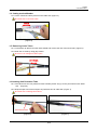
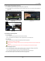
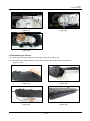
VSOF-CS201A
ODP Aerial Closure for Fiber Optic Cable
User Manual Rev.1
CS201A
User Manual Rev.1
1. Direction
1.1 Getting Started
1.1.1 Confirm the cable structure and the fiber type before starting the work. Different types of fibers
cannot be spliced together.
1.1.2 Seal the splicing part perfectly to minimize cable damages by moisture. Do not apply any impact to
the splicing part.
1.1.3 Keep the working place free from moisture or dust. Do not give any impact on the cables. Do not
bend or twist cables.
1.1.4 During the sheath stripping and the closure assembly procedures, use permitted tools according to
an approved fiber optic splicing standard in your region.
1.2. Marking a Cutting Point
1.2.1 Mark a sheath removing point on the cable with a piece of tape at a 700mm point from right and left
the Closure Installation point. (Figure-1)
1.2.2 Divide messager wire and cable from marking point by cutter (Figure-2)
700mm
[Figure-1]
[Figure-2]
1.3. Sheath Removing
1.3.1 Remove the cable sheath from the marked point using a sheath stripper. (Figure-3)
Be sure not to damage the fiber optics.
30mm
[Figure-3]
[Figure-3-1]
2/10
CS201A
User Manual Rev.1
1.4. Cutting tension Member
1.4.1 Cut the T/M at the 70mm point from the cable end. (Figure-4)
Be careful not to cut loose tubes.
70mm
[Figure-4]
1.5. Removing Loose Tubes
1.5.1 Leave about 40~60mm from the cable sheath end remove the rest of the loose tube. (Figure-5)
1.5.2 Clean the cut area by using jelly cleaner.
Be sure not to damage the fiber optics.
40~60mm
[Figure-5]
1.6 Inserting Unit Protection Tube
1.6.1 Insert fibers into the unit protection tubes carefully all the way up to the point where loose tubes
end.
(Figure-6)
1.6.2 Wrap the tape around the end point of protection tube at cable side. (Figure-7)
Be careful not to damage inner fibers.
Unit Protection Tube
[Figure-6]
[Figure-7]
3/10
CS201A
User Manual Rev.1
1.7 Fixing Cable sheath and Tension Member
1.7.1 Apply the grease in the middle of sheath gasket of the closure. (Figure-8)
[Figure-8]
1.7.1 Put the T/M supporter cover on the T/M and tighten them together. (Figure-9)
[Figure-9]
[Figure-9-1]
1.8 Fixing Sheath Holder & Messnger Wire Cover
1.8.1 Apply the high vacuum grease on the upper sheath gasket. (Figure-10)
1.8.2 Fix the cable sheath holder, main gasket holder and messenger wire cover by using a screwdriver.
(Figure-11, 12, 13)
[Figure-10]
[Figure-11]
[Figure-12]
[Figure-13]
4/10
CS201A
User Manual Rev.1
1.9 Arranging & Fixing Protection Tube
1.9.1 Attach the protection tube using a cable tie and cut the cable tie (Figure-14, 15, 16)
1.9.2 Arrange a fiber optic unit considering the bending radius. (Figure-17)
[Figure-14]
[Figure-15]
[Figure-16]
[Figure-17]
1.10 Connecting the pigtail
1.10.1 Connect the pigtail on the module.(Figure-18, 19)
1.10.2 Arrange fiber optic units considering the bending radius. (Figure-20)
1.10.3 Put units into the hole on the other side. (Figure-21)
[Figure-18]
[Figure-19]
[Figure-20]
[Figure-21]
5/10
CS201A
User Manual Rev.1
1.11 Arranging & Fixing Pigtail (Tray Part)
1.11.1 Arrange the pigtail considering the bending radius. (Figure-22)
1.11.2 Insert pigtail into the sprial protection tubes carefully all the way up to the point where pigtail end.
(Figure-23)
1.11.3 Attach the pigtail protection tube using a cable tie and cut the cable tie (Figure-24)
[Figure-22]
[Figure-23]
[Figure-24]
1.12. Splicing and Storing Fibers
1.12.1. Preparation
1.12.1.1. Clean the working desk and check the fibers carefully.
1.12.1.2. Cut each fiber end carefully to make a perpendicular cut to the fiber axis
1.12.2. Splicing
1.12.2.1. Splice fibers in accordance with splicing method to approved.
Be careful not to twist or bend fibers.
There should be no damage or flaw on the cut area and keep the fibers from dust to minimize the
data loss.
If there is any problems with the splice, then cut the splicing point and splice them again.
1.12.3. Arranging the splices
1.12.3.1. After the splice, insert the splice protection sleeve in each slit accordingly. (Figure-25)
1.12.3.2. Coil surplus fibers in the tray in a figure 8 shape.(Figure-26)
1.12.3.3. After the arrangement, apply the O-ring into the slit and close the tray lid.
1.12.4. Record each splice on the index card on the lid. (Figure-27)
6/10
CS201A
User Manual Rev.1
[Figure-25]
[Figure-26]
[Figure-27]
1.13 Connecting Drop cable connector
1.13.1 Fix Drop Cable by Drop Cable holer. (Figure-28, 29 )
1.13.2 Fix Drop Cable holder. (Figure-30, 31 )
1.13.2 Insert Drop cable gasket. (Figure-32)
1.13.3 After work completion, Fix Drop cable at the main cable by cable tie. (Figure-36)
[Figure-28]
[Figure-29]
[Figure-30]
[Figure-31]
7/10
CS201A
User Manual Rev.1
Using the hole
[Figure-32]
[Figure-33]
1.14 Preparing Distribution Cables
1.14.1 Do the step from 1.2 to 1.7. One different thing is a cutting point of a sheath is 120cm point from the
cable cut end. (Figure-34)
[Figure-34]
1.15 Inserting Distribution Cables
1.15.1 drill a hole in the 2 port gasket by the screw drive (Figure-35)
1.15.2 Apply the high vacuum grease inside drilled hole
1.15.2 Insert the distribution cable into the 2 port gasket. (Figure-36, 37)
[Figure-35]
[Figure-36]
[Figure-37]
8/10
CS201A
User Manual Rev.1
1.16 Fixing Tension Member of Distribution Cables
1.16.1 Put the T/M supporter cover on the T/M and tighten them together by using screw driver.
(Figure-38, 39)
[Figure-38]
[Figure-39]
1.17 Fixing 2 port Sheath Holder
1.17.1 In case of 8~9mm Cable, apply sheath fixing gasket. (Figure-40)
1.17.2 Fixing from bolt middle of 2port sheath holder
(Figure-41)
[Figure-40]
[Figure-41]
1.18 Arranging Protection Tube and Fiber
1.18.1 Arrange the protection tubes using the cable guide saddle under the tray. (Figure-42)
1.18.2 Arrange the protection tubes considering the bending radius. Insert the protection tubes into the
inlet on the tray and fix by using cable ties. (Figure-43, 44)
1.18.3 Coil surplus fibers in the tray in a figure 8 shape. (figure-45)
1.18.4 Record each splice on the index card on the lid. (figure-46)
[Figure-42]
[Figure-43]
9/10
CS201A
User Manual Rev.1
[Figure-44]
[Figure-45]
[Figure-46]
1.19 Assembling the Closure
1.19.1 Push front of Handle until there is a sound such as clack. (Figure-47)
1.19.2 In case of drop cable moved the other side,use Drop Cable guide at main body bottom
(Figure-49, 50)
[Figure-47]
[Figure-48]
[Figure-49]
[Figure-50]
10/10