1
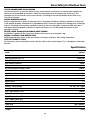
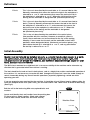
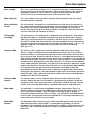
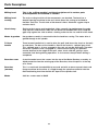
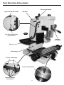
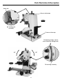
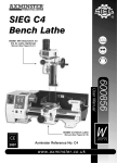
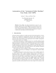
Code 505103
XN2 Super
Tilt Head Mill Drill
Index of Contents
Page No
Index of Contents
01
Declaration of Conformity
02
What’s Included
03
General Instructions for 230V Machines
04
Basic Safety for Machine Tools
05-06
Specifications
06
Definitions
07
Initial Assembly
07
Parts Description
08-09
Parts Illustration & Description
10-11-12
Operating Instructions
13-14-15
Collet Chuck Assembly (Optional)
16-17
Maintenance
17-18-19
Troubleshooting
20-21
Parts Breakdown Part 1,2,3
22-23-24
Parts List
25-26-27-28-29
Notes
30
symbols below advise that you follow the correct safety procedures when
Warning The
using this machine.
Fully read manual
and safety instructions
before use
Eye protection
should be worn
Ear protection
should be worn
01
Foot protection
should be worn
Declaration of Conformity
Copied from CE Certificate
The undersigned,
authorised
by Shanghai SIEG Machinery Co., Ltd.
No.555 Caofeng Rd. South to No.17 Bridge of
Caoan Rd. Shanghai, P.R. China
declares that this product:
MILLING MACHINE
XN2
manufactured by Shanghai SIEG Machinery Co. is
in compliance with the following standards or
standardisation documents in accordance with
Council Directives
EN 61029-2-5: 2002
EN 61029-1:2000+A11:2003+A12:2003
EN 55014-1:1993+A1:97+A2:99
EN 55014-2:1997
EN 61000-3-2:2000
EN 61000-3-3:1995/+A1:2001
02
What’s Included
Model Number
1 No.
1 No.
1 No.
1 No.
1 No.
1 No.
1 No.
1 No.
2 No.
1 No.
1 No.
1 No.
1 No.
A
B
C
D
E
F
G
H
I
XN2
SIEG Super X2 Mill with (1-13mm Chuck & B16 Taper)
Chuck Key
Tommy Bar
Morse Taper Drift
Oil Can
8 x 10mm Double End Spanner
12 x 14mm Double End Spanner
3,4,5,6mm Hex Keys
‘T’ Slot Keepers
Position Key
Spare Fuse
Guarantee Card
Instruction Manual
E
D
F
B
A
I
G
C
H
!
Please read the Instruction Manual prior to using your new machine; as well as
the installation procedure, there are daily and periodic maintenance recommendations
to help you keep your machine on top line and prolong its life. Keep this Instruction
Manual readily accessible for any others who may also be required to use the machine.
Having unpacked your machine and its accessories, please check the contents against the equipment
list "What’s Included", if there are any discrepancies, please contact Axminster Tool Centre using the
procedures laid down in the catalogue. Please dispose of the packaging responsibly, much of the
material is bio-degradable. The machine and its accessories will arrive coated with heavy corrosion
preventative grease. This will need to be cleaned from the machine, its components and accessories
prior to it being set up and commissioned. Use coal oil, paraffin or a proprietary degreaser to remove
the barrier grease. Be warned, it will stain if you splash it on clothing etc., wear overalls, coverall et al.,
rubber gloves are also a good idea, as is eye protection if your cleaning process tends to be a little bit
enthusiastic. After cleaning, lightly coat the exposed metal surfaces of the machine with a thin layer of
light machine oil. N.B If you used paraffin/kerosene make sure you apply this thin film sooner rather than
later.
03
General Instructions for 230V Machines
Good Working Practices/Safety
The following suggestions will enable you to observe good working practices, keep yourself and fellow workers safe
and maintain your tools and equipment in good working order.
!
WARNING!!
KEEP TOOLS AND EQUIPMENT OUT
OF THE REACH OF YOUNG CHILDREN
Mains Powered Tools
Primary Precautions
These machines are supplied with a moulded 13 Amp. plug and 3 core power cable. Before using the machine
inspect the cable and the plug to make sure that neither are damaged. If any damage is visible have the damaged
item inspected/repaired by a suitably qualified person. If it is necessary to replace the plug, it is preferable to use an
‘unbreakable’ type that will resist damage on site. Only use a 13 Amp plug, and make sure the cable clamp is
tightened securely. Fuse as required. If extension leads are to be used, carry out the same safety checks on them,
and ensure that they are correctly rated to safely supply the current that is required for your machine.
Work Place/Environment
The machine is not designed for sub-aqua operation, do not use when or where it is liable to get wet. If the machine
is to be used outside and it starts to rain, stop work and move it inside. If machine has got wet; dry it off as soon as
possible, with a cloth or paper towel. Do not use 230V a.c. powered machines anywhere within a site area that is
flooded or puddled, and do not trail extension cables across wet areas. Keep the machine clean; it will enable you
to more easily see any damage that may have occurred. Clean the machine with a damp soapy cloth if needs be, do
not use any solvents or cleaners, as these may cause damage to any plastic parts or to the electrical components.
Keep the work area as uncluttered as is practical, this includes personnel as well as material.
!
(Under no circumstances should CHILDREN be allowed in work areas)
It is good practice to leave the machine unplugged until work is about to commence, also make sure to unplug the
machine when it is not in use, or unattended. Always disconnect by pulling on the plug body and not the cable.
Once you are ready to commence work, remove any tools used in the setting operations (if any) and place safely
out of the way. Re-connect the machine.
Carry out a final check e.g. check the cutting tool, drill bit, saw blade etc., is securely tightened in the machine,
check you have the correct speed and function set, check that the power cable will not ‘snag’ etc.
Make sure you are comfortable before you start work, balanced, not reaching etc.
If the work you are carrying out is liable to generate flying grit, dust or chips, wear the appropriate safety clothing,
goggles, gloves, masks etc., If the work operation appears to be excessively noisy, wear ear-defenders. If you wear
your hair in a long style, wearing a cap, safety helmet, hairnet, even a sweatband, will minimise the possibility of your
hair being caught up in the rotating parts of the machine, likewise, consideration should be given to the removal of
rings and wristwatches, if these are liable to be a ‘snag’ hazard. Consideration should also be given to non-slip
footwear, etc.
DO NOT work with cutting or boring tools of any description if you are tired, your attention is wandering or you are
being subjected to distraction. A deep cut, a lost fingertip or worse; is not worth it!
DO NOT use this machine within the designated safety areas of flammable liquid stores or in areas where there may
be volatile gases. There are very expensive, very specialised machines for working in these areas, THIS IS NOT
ONE OF THEM.
Check that cutters, drills, blades etc., are the correct type and size, are undamaged and are kept clean and sharp,
this will maintain their operating performance and lessen the loading on the machine. Above all, OBSERVE…. make
sure you know what is happening around you, and USE YOUR COMMON SENSE.
04
Basic Safety for Machine Tools
KNOW YOUR MACHINE TOOL
Read and understand the owner's manual and labels affixed to the tool. Learn its application and limitations as well as
specific potential hazards peculiar to the tool.
KEEP GUARDS IN PLACE
Keep all guards in place. They are there for your protection and do not interfere with the correct operation of your
machine.
REMOVE ADJUSTING KEYS AND WRENCHES
Form the habit of checking to see that keys and adjusting wrenches are removed from the machine
before turning it on.
KEEP WORK AREA CLEAN
Cluttered areas and benches invite accidents. Floors must not be slippery due to liquids or dust. Make sure you clean
up any waste materials on completion of work.
AVOID DANGEROUS ENVIRONMENTS
Do not use power tools in damp or wet locations or expose them to rain. Keep work area well lit. Provide adequate
space surrounding the work area.
KEEP CHILDREN AWAY FROM WORK AREA UNLESS UNDER CLOSE SUPERVISION
All visitors should be kept a safe distance from work area. Children are naturally curious; therefore ensure they are
closely supervised when they are near the work area.
MAKE WORKSHOP TAMPER PROOF
Many machines have lockable switches that can be secured with a small padlock or have a removable key. Please
make use of them to prevent unauthorised operation of your machines.
DO NOT FORCE TOOL
It will do the job better and safer at the rate for which it was designed. Develop a patient approach to the work, you will
get better results in the finished product.
WEAR PROPER CLOTHING
Do not wear loose clothing, gloves, neckties or jewellery that can catch in moving parts of machinery. Non-slip footwear
with steel toecaps is recommended. Wear protective hair covering to contain long hair. Roll up long sleeves to above
the elbow.
SECURE WORK
Where applicable use clamps or a vice to hold work. This leaves both hands free to operate the tool correctly and thus
produces better results.
DIRECTION OF FEED
Feed work into a blade or cutter against the direction of rotation of the blade or cutter only. This will reduce the
danger of kick back which is a serious hazard. Similarly, when using a lathe, feed the cutting edge of the tool against
the direction of rotation!
USE SAFETY GOGGLES AND FACE PROTECTION
Wear safety goggles (complying to relevant standards) at all times. Normal spectacles only have impact resistant
lenses and are NOT sufficient. Also use face or dust masks if the cutting operation is dusty (connection of machine to
a dust extractor is preferred). Always wear ear defenders for cutting, sawing, planing or routing operations. Your
hearing can be permanently damaged if exposed to high noise levels for long periods of time.
DO NOT OVERREACH
Keep proper footing and balance at all times.
MAINTAIN TOOL WITH CARE
Keep tools sharp and clean at all times for the best and safest performance. Follow the manufacturer's instructions for
lubricating and sharpening and also for changing accessories.
DISCONNECT POWER FROM THE TOOL
Before servicing or when changing accessories always disconnect the power supply to avoid accidental starting.
AVOID ACCIDENTAL START UP
Although most machines are now equipped with NVR switches, develop the habit of making sure the switch is in the
"OFF" position before connecting the machine to the power supply.
05
Basic Safety for Machine Tools
USE RECOMMENDED ACCESSORIES
Consult the owner's manual for details of any manufacturer's accessories or contact your supplier for
details of recommended accessories. Follow the instructions that accompany the accessory. The
improper use of accessories may cause hazards. The fitting of non-recommended accessories may
also cause hazards.
CHECK DAMAGED PARTS
Before using the tool, a guard or other part that is damaged should be carefully checked to ensure that
it will operate properly and perform its intended function. Check for alignment of moving parts, breakage
of parts, mounting and any other conditions that may affect its operation. A guard or other part that is
damaged should be properly repaired or replaced. A parts list is to be found at the back of your
operator's manual.
NEVER LEAVE A MACHINE RUNNING UNATTENDED
ALWAYS turn power off. Do not leave machine until it comes to a complete stop.
DRUGS, ALCOHOL AND MEDICATION
NEVER operate tools whilst under the influence of drugs, alcohol or after taking medication.
USE THE CORRECT TOOL
Do not force a tool or attachment to do a job for which it was not designed. This is dangerous workshop
practice.
Specification
Code
505103
Power
230V 50Hz 500W
Drilling Capacity (ST 37)
13mm/M8
Face Milling Capacity
30mm
End Milling Capacity
16mm
Throat
160mm
Distance between Spindle/Table
320mm
Thread Pitch of Lead Screw
2mm
Lead Screw Diameter
M14
Spindle Taper
MT-2 / M10
Spindle Speed (Variable)
50-2500rpm
Speed Ratio
1:2
Spindle Stroke
60mm
Column Tilting Range
45˚Left / 30˚ Right
Max. Table Stroke x-axis
250mm
Max. Table Stroke y-axis
160mm
Max. Table Stroke k-axis
300mm
Max. Tapping Size (HT200)
M8
Max. Tapping Size (45)
M6
Max. Milling Diameter
ø30mm
Table Size
130 x 500mm
Overall Size: (LxWxH)
610 x 610 x 780mm
Weight
127kg
06
Definitions
‘X’ Axis.
This is the axis described by the work table as it is moved side to side.
Normally, movement that moves the tool to the right in the workpiece is
referred to as +ve ‘X’, and movement that moves the tool to the left in
the workpiece is referred to as –ve ‘X’. Where the initial position of the
tooling and the worktable is designated 0,0. (Horizontal plane only).
‘Y’ Axis.
This is the axis described by the work table as it is moved from front to
back. (Traverse) Normally movement that moves the tool to the front in
the workpiece is referred to as-ve ‘Y’, and movement that moves the
tool to the rear in the workpiece is referred to as+ve ‘Y’. Where the
initial position of the tooling and the worktable is designated
0,0.(Horizontal plane only).
‘Z’ Axis
This is the axis described by the worktable in the vertical plane.
(Not possible with this machine). However, to establish a point in
space, the co-ordinates can be transferred to the ‘tip’ of the tooling,
whereby, if we assume that the tool and the worktable in their initial
positions, where designated 0,0,0, (Horizontal and vertical planes) any
point above the tool tip is referred to as +ve ‘Z’, and any point below
the tool tip is referred to as -ve ‘Z’
Initial Assembly
Ideally, your mill should be installed close to a correctly rated power supply, in a warm
dry environment, well ventilated and illuminated by bright clear natural light, with
adequate access all around the machine, and sufficient adjacent storage space for your
tools, accessories and material.
The Mill is best mounted on a rigid bed; this is to ensure stability of the machine and to attenuate any
vibration that is generated when the machine is running.
The bed should be flat and set level in both planes, and at a height that enables comfortable operation of
the machine. It is not necessary to anchor the bed through to the floor, but it must be stable enough to
remain immovable during any normal forceful operations (especially tightening) carried out whilst
operating your mill.
If you are preparing your own bed for the machine, it should be at least 552mm long by 390mm wide; (to
cover the footprint of the base (506 x 352), you will need to drill 4 No. 10mm holes to allow for bolt fixing.
(See Fig A)
Fig A
Locate and identify the 3 rod handles from the packing box.
Fit these to the 3 wheel handles, (Work table control,
traverse feed control, head raise and lower control.)
506mm
Bolt the mill to the bed using M10 nuts,caphead bolts and
washers.
Machine Base
10mm Hole
352mm
07
Parts Description
Base casting
This is the stand for the milling m/c. It is a square casting with a seated flange to
the rear, which mounts the main tool post. There are four holes to each corner to
be bolted to a bench or stand. There is a dovetail slide machined to the front
service of the base, to mount the traverse slide of the work table.
Main tool post
This is the column of the mill, with a dovetail slide machined on the front which
the milling head is mounted.
Rise & fall drive
screw
The rise and fall is anchored in a machined housing at the top of the tool post. It
has a wheel with a graduated ring (thimble), so the movement of the slide can be
measured. The wheel is connected to a rod shaft that enable the screw to be
turned, allowing the head to move up and down. Turning the handle clockwise will
raise the head and anti-clockwise to lower it.
Tilt housing
assembly
The tilt housing is a turntable which is integrated in the milling head. Mounted on
top of the tool post is a threaded locking pin that locks the head at 90˚ degrees
(See fig 3), turning the 10mm nut (clockwise) will drive the pin up thus unlocking
the head. On either side of the head there are two rounded nuts that clamp the tilt
assembly in position. Loosening the nuts will allow the head to pivot + 45˚ or - 45˚
degrees, using the scale and pointer on the right hand side of tilt housing.
(See figs 1 & 7)
Traverse slide
The traverse slide casting mounts onto the dovetail slide of the base casting.
There is a gybe strip fitted to the left side dovetail to maintain the fit. In the front
face of the slide is a machined housing which mounts and anchors the drive shaft
for the traverse feed. Under the slide (on the base) is a threaded dog mounted in a
fixed position, through which the traverse drive shaft is threaded so as to enable the
slide to be driven back and forth. The top of the traverse slide has a female dovetail
machined into it, perpendicular to the lower dovetail. This marries with the dovetail
on the underside of the worktable. The front face of the dovetail is fitted with a gybe
strip to maintain the fit. The top of the slide also has a fixed threaded dog mounted
to it, through which the drive shaft of the worktable is threaded to allow the
worktable to be driven from side to side. In between the grubscrews and locknuts
of the gybe strip adjustor is M4 caphead bolt handles that can be driven forward to
clamp the gybe strips against the dovetails to enable the traverse and longitudinal
movements to be locked in position.
Traverse slide
control
The traverse slide is driven using the wheel and rod handle at the front of the
machine. Behind the boss of the handle is a graduated ring (thimble) so that the
movement of the slide can be measured. The thimble is held to the drive shaft by
friction, and can be pre-positioned to a predetermined start or stop dimension.
Work table
The worktable is a machined casting 500mm long by 130mm wide. There is a
dovetail section machined in the underside to mate with the traverse slide. There
are 4 x 16mm open ended ‘T’ slots machined in the table along its length, to
facilitate the fixing of machine vices or clamps. The worktable is mounted onto the
traverse slide. The right end face of the worktable has a housing machined in it to
mount and anchor the drive shaft assembly.
Work table
control
The Worktable slide is driven using the wheel and rod handle at each end of the
table. Behind the boss of the handle is a graduated ring (thimble) so that the
movement of the worktable can be measured. The thimble is held to the drive shaft
by friction, and can be pre-positioned to establish a predetermined start or stop
dimension.
08
Parts Description
Milling head
This is the ‘milling machine’ and the descriptions of its various parts
and components are detailed as follows:-
Milling head
casting
The main casting to which all the components are attached. The head has a
dovetail housing machined at the rear, which allows the casting to be fitted to
the Main Tool Post. The left side of the dovetail slide is fitted with a gybe strip to
maintain the fit.
Head clamp
Similar to the traverse and longitudinal slides, centrally located between the gybe
strip adjusters and locknuts there are two M4 bristol handled bolts that clamp the
gybe strip against the slide to effect a locking action for the rise and fall of the head.
Motor & gearbox
the gearbox assembly is mounted inside the head box casting. The motor drive is
geared through to the spindle.
Tri-lever
handle
Three levered handle that is used to drive the quill (and hence the chuck or the tool)
up and down. The boss of the handle is fitted to the end of a ‘splinted’ gear shaft.
This ‘splinted’ gear is, in turn, engaged in the rack cut into the quill body. The other
end of the ‘splinted’ shaft is engaged in a contra-wound spring, this provides
counter balance to the weight of the quill, arbor, chuck and drill, giving a more
controlled ‘feel' during drilling operations. It also retracts the quill when drilling is
completed.
Draw bar cover
A steel threaded cover that screws into the top of the Motor Gearbox assembly, to
afford protection from the rotating top of the draw bar, when the quill is at the top
of its travel.
Draw bar
(unseen)
This is a metal rod, threaded M10 at one end and with an 8mm squared shank and
flange machined on the other. It is fitted through the spindle mandrel to hold the
fitted tool/tooling hard into the No2 MT taper of the spindle shaft.
Motor
230V d.c. motor rated at 500W.
09
Parts Illustration & Description
Tilt housing
Draw bar
Typ. 3 Spindle
automatic return
button
Scale
Tri-lever feed
handle
Fine feed
control knob
(see page 14)
D.R.O control
(see page 13)
Fine feed
clutch knob
Guard
Pointer
Fig 1
Control panel
(see page 12)
Work table
Chuck
Machine base
‘T’ Slot
Drip cover
Traverse slide
control handle
Work table drive handle
Positive stop plate
Typ. 2 Adjustable stop
Gibs strip adjusters
Worktable thimble
10
Longitudinal feed clamp
Parts Illustration & Description
Rise and fall handle
Typ.2 Rise and fall clamps
Typ. 6 Rise and fall gib
strip adjusters
Tool post
Fig 2
Spindle
lock handle
Tool tray
Main tool post
Traverse slide clamps
Traverse slide thimble
Traverse slide gib
strip adjusters
11
Parts Illustration & Description
10mm nut
Rise & fall thimble
Fig 3
90˚ Locking pin
assembly
Traverse slide stop
Tilt housing clamps, two on
each side of the milling head.
-45˚
+45˚
Fig 4
Tilt housing assembly
12
Operating Instructions
Control Panel
1. Make sure the correct fuse is in the fuse box and the power switch is off. Unlock the emergency stop
button, connect the machine to mains and switch on. The power light on the control panel will come on.
2. When the machine is on, press the (start) button, the motor starts up. Press the button (
increase the speed, while pressing (
forward rotation, while (
) will decrease the speed. Press the (
) to
) to control the
) controls the backward rotation. Pressing the (TAPPING) button, will slow
down the spindle’s rotation to 0-500rpm, as above, and the word TAPPING will appear on the controls
display. The switches on the handles control the spindles rotation, forward and reverse. Pressing the
(STOP) button, will stop the machine.
Note: The circuit boards on the machine has an overload protection function. If the material you are
drilling or milling is over excessive volume, it will cause the machine to automatically stop and will
display an error message on the LCD, on the control panel.
Remove the material from the machine, reset the machine by switching the power switch on/off and
continue with operation.
5
1
9
6
11
2
7
Parts Identification
1. Power Light
2. Fuse
3
3. Emergency Stop Button
4. Control Panel
5. LCD Display
6. Power Switch
13
7. Speed increase Button
8. Speed Decrease Button
9. Forward Rotation Button
10. Backward Rotation Button
8
11. Tapping Button
12. Start Button
4
10
13. Stop Button
13
12
Operating Instructions
D.R.O. Control
Digital Read Out (DRO) (Fig 5)
For normal drilling operations press the ON/OFF switch first, and then press the “ZERO” button. Press
“mm/in” button to select metric or imperial readings. These two buttons can be effected regardless of the
down feed handle position, then you can start drilling. The readings on the display can be amended at
any time by pressing “plus” or “minus” buttons.
When displaying error (e.g. no readings or flashing) it means the batteries are low and need replacing.
Push against the arrow showing in (Figs 5a & 5b) to open the battery cover, withdraw the battery for
replacement. The voltage of the Zinc button batteries is 1.2 volts. After replacement, re-fit the cover.
Fig 5
Min/in
Digital display
Press “mm/in” button to
select metric or imperial
readings.
Plus & Minus
On/Off
The readings on the display
can be amended at any
time by pressing “plus” or
“minus” buttons.
For normal drilling operations
press the ON/OFF switch first,
and then press the
“ZERO” button.
Fig 5b
Fig 5a
Removing battery cover
1.2 volt zinc button battery
14
Operating Instructions
Engaging the fine feed control
1) Turn the fine feed clutch knob clockwise until it becomes tight (DO NOT OVERTIGHTEN), thus
engaging the fine feed control mechanism (See fig 6).
2) Turn the fine feed control knob to lower or raise the spindle in gradual movements (See fig 7).
3) To disengage the fine feed control turn the clutch knob anti-clockwise until it is loose.
Fine feed control knob
Engage
Fig 6
Disengage
Turn the clutch knob clockwise to engage
the fine feed control,turning the knob
anti-clockwise will disengage it.
Fine feed clutch knob
Fig 7
Turn the fine feed control knob to lower or
raise the spindle in slow succession
15
Collet Chuck Assembly (Optional)
The chuck can be removed and replaced with an optional collet chuck for milling operations. Please
follow the instruction below for chuck removal.
!
DISCONNECT THE MACHINE FROM THE MAINS SUPPLY
1) Unscrew the draw bar cover and safely put to one side (See fig 8). Turn the spindle lock handle
clockwise to lock the spindle. (See page 11)
Blind pocket
Draw bar cover
Arbor
Hex key recess
Fig 8
Tommy
bar
Spindle
Fig 9
2) Open the chuck guard, locate a 8mm hex key and the tommy bar. Insert the tommy bar into the blind
pocket’s recess in the spindle (See fig 9), insert the 8mm hex key into the top of the arbor, as shown in
figs 8 & 10.
3) While holding the tommy bar rotate the hex key anticlockwise (one turn) until part of the arbor is
showing (See fig 10)
Arbor
Fig 10
Hex key
Brass/wood hammer
Fig 11
Fig 12
13mm
chuck
B16 taper
4) Remove the hex key and tommy bar, support the chuck with one hand and using a brass or wooden
hammer strike the arbor to release the chuck taper from the spindle taper. Unscrew the chuck from the
arbor and remove. (See figs 11 & 12)
16
Collet Chuck Assembly (Optional)
Fig 13
4) Insert the collet chuck into the spindle taper and screw it onto the
arbor shaft. Hold the collet chuck, using an adjustable or ‘C’ spanner
(See fig 13). Insert the 8mm hex key into the recess on top of the
arbor as shown in figs 8 & 10, while holding the chuck tighten the
arbor (DO NOT OVERTIGHTEN)
5) Replace the draw bar cover, release the spindle lock handle,
reconnect the mill to the mains and continue with the operation.
Collet chuck
“C” or adjustable Spanner
Maintenance
Oiling Points
Fig 14
Oil
OIL
17
Maintenance
Worktable and Traverse feed adjustment
The worktable and the traverse feed are both mounted over dovetail sections. In order to
maintain the ‘tightness’ of the fit; between the sloping surface of the component and its mating
surface a gybe strip has been inserted. (At the front of the worktable, and to the left hand side
of the traverse feed).
To adjust the gybe strips, use a 8mm spanner and a flat ended screwdriver, release the lock nuts
and screw the gybe strip grubscrews clockwise to compensate for any slackness or anti-clockwise
to loosen the movement. Check, using the feed handles, that worktable and the traverse feed moves
smoothly, If not, repeat the adjustments until the movement is smooth and tight over the whole of
the travel. (See figs 15 & 16)
8mm spanner
Fig 16
Gybe strip
Fig 15
Screwdriver
Milling Head adjustment
The Milling Head is mounted over a dovetail section. In order to maintain the ‘tightness’ of the fit;
between the sloping surface of the component and its mating surface, on the left hand side, a gybe
strip has been inserted. To adjust the gybe strips, use the supplied 8mm spanner, release the lock nuts
and screw the gybe strip grubscrews clockwise to compensate for any slackness or anti-clockwise to
loosen the movement. Check, using the rise and fall drive feed handle, that the head moves smoothly,
If not, repeat the adjustments until the movement is smooth and tight over the whole of the travel.
(See fig 17)
Rise & fall
handle
Mill head
gybe strip
adjusters
Fig 17
18
Maintenance
Your Mill is a precision tool. In order to maintain this precision and prolong its useful life, it is
advised that you follow the recommended daily and periodic maintenance tables printed below.
Daily and Periodic Maintenance
Daily
1. Carry out a visual inspection. Repair any damage immediately. Minor damage to the beds
should be taken out with an oilstone.
2. Move the worktable and the traverse feed back and forth by hand, check that the movement
is smooth.
3. Spread a light film of oil over the worktable and the traverse slide bed.
4. Oil the end bearings of the drive shafts. Squirt oil onto the slide faces of mating components.
Exercise the components to ensure the oil is spread over both visible and obscure surfaces.
Daily after-use
1. Clean all swarf and chips away from the machine bed, slide surfaces, and the tool post.
2. Exercise the slides and ensure no swarf etc., is lodged in the drive shaft tunnels.
If you have been using a coolant make sure the machine is thoroughly dried off.
3. Check the tool, ensure it is usable the next time, if not re-sharpen or replace the tool tip.
4. Lightly oil spray all the machine beds and surfaces.
5. Clean and lightly oil any tools you may have been using (drill chucks, spanners,
chuck keys etc), and put them away.
6. Switch off the power supply. Disconnect the plug.
7. Cover the machine over with a dust cloth.
Weekly
1. Move the traverse slide fully back to give access to the tunnel, blow out to make sure all swarf
is cleared away and heavily spray oil the tunnel, exercise the slide to work the oil into the drive
thread and to lubricate the dog.
2. Spray oil the slide and the worktable bed, exercise the worktable to spread the oil to all
surfaces, both hidden and visible.
3. Spray oil the underside of the machine onto the drive screws, exercise to ensure the oil is
coating all components.
4. Clean and spray oil the rise and fall drive screw, exercise to ensure all parts are coated.
5. Check the movement of the worktable, the traverse slide and the head, check they
are smooth and ‘tight’, if necessary reset the gybe strips until the movements are smooth and
tight.
6. Wipe the quill outer sleeve clean and lightly oil, exercise the quill to spread the oil in
the sleeve bushes.
Monthly
a) Give the motor a good ‘blow through’ to remove any dust, dirt etc.
b) Check all the interlocks function correctly.
Accessories
There are numerous accessories for the machine listed in the Axminster catalogue.
19
Troubleshooting
20
Troubleshooting
21
Parts Breakdown Part 1
22
Parts Breakdown Part 2
23
Parts Breakdown Part 3
24
Parts List
25
Parts List
26
Parts List
27
Parts List
28
Parts List
29
Notes
30
Please dispose of packaging for the product in a responsible manner. It is suitable for recycling.
Help to protect the environment, take the packaging to the local recycling centre and place into the
appropriate recycling bin.
Only for EU countries
Do not dispose of electric tools together with household waste material. In observance of European
Directive 2002/96/EC on waste electrical and electronic equipment and its implementation in
accordance with national law, electric tools that have reached the end of their life must be collected
separately and returned to an environmentally compatible recycling facility.
Axminster Tool Centre,
Unit 10 Weycroft Avenue, Axminster, Devon EX13 5PH
axminster.co.uk