1
Parts Description
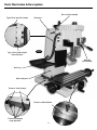
Milling head
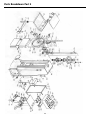
This is the ‘milling machine’ and the descriptions of its various parts
and components are detailed as follows:-
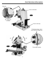
Milling head
casting
The main casting to which all the components are attached. The head has a
dovetail housing machined at the rear, which allows the casting to be fitted to
the Main Tool Post. The left side of the dovetail slide is fitted with a gybe strip to
maintain the fit.
Head clamp
Similar to the traverse and longitudinal slides, centrally located between the gybe
strip adjusters and locknuts there are two M4 bristol handled bolts that clamp the
gybe strip against the slide to effect a locking action for the rise and fall of the head.
Motor & gearbox
the gearbox assembly is mounted inside the head box casting. The motor drive is
geared through to the spindle.
Tri-lever
handle
Three levered handle that is used to drive the quill (and hence the chuck or the tool)
up and down. The boss of the handle is fitted to the end of a ‘splinted’ gear shaft.
This ‘splinted’ gear is, in turn, engaged in the rack cut into the quill body. The other
end of the ‘splinted’ shaft is engaged in a contra-wound spring, this provides
counter balance to the weight of the quill, arbor, chuck and drill, giving a more
controlled ‘feel' during drilling operations. It also retracts the quill when drilling is
completed.
Draw bar cover
A steel threaded cover that screws into the top of the Motor Gearbox assembly, to
afford protection from the rotating top of the draw bar, when the quill is at the top
of its travel.
Draw bar
(unseen)
This is a metal rod, threaded M10 at one end and with an 8mm squared shank and
flange machined on the other. It is fitted through the spindle mandrel to hold the
fitted tool/tooling hard into the No2 MT taper of the spindle shaft.
Motor
230V d.c. motor rated at 500W.
09