1
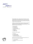
TM
Converter
USER MANUAL
The Response ConverterTM network interface allows you to convert 192 DMX512 signals
to AMX192 or 192 AMX192 signals to DMX512. The compact interface box features an
optically isolated DMX512 link and a 100 hertz output update rate. This manual provides
information on all Response Converter controls, connectors and indicators.
7
8
23
901
6
99 0 11
5
7788
➒
4
78
❽
3
23
456
➎ ➏ ❼
2
78
2233
1
901
PUSH
❹
456
➊
❷
❸
❹
➎
➏
❼
❽
➒
❿
❸
5
44 5 66
DMX512 Input
DMX512 Output
AMX192 Output
AMX192 Input
Reset switch
Indicator LEDs
DMX512 termination switch
Adjustment pots
DIP switches
Number switches
AC power cable
❷
PUSH
➊
➓
11
11
To use Response Converter, follow these steps:
1. Plug power cable into a 120 VAC outlet.
2. For DMX512 to AMX192 operation, set DIP switch 3 down and switch 4 up. If optical
isolation is desired, set DIP switch 1 up. For AMX192 to DMX512 operation, set DIP
switch 1 down, switch 3 up and switch 4 up.
3. Press Reset.
4. Insert input and output cables into appropriate connectors.
5. Set number switches to starting dimmer output number (see page 2).
6. If Response Converter is the last device in a DMX512 data link, set DMX512
terminator switch On (right). In AMX192 to DMX512 mode, leave terminator switch Off
(left).
7. See following pages for adjustment pot settings and additional information on switch
functions and settings.
Note: When data flow is interrupted, all outputs fade to zero percent after three minutes.
Entering starting analog dimmer address
0
0
1
The rotary number switches allow you to set the control signal number for the first
output dimmer. The remaining 191 analog outputs are consecutively numbered from
that number.
Set the rotary number switches to a starting number between 001 and 512 for
DMX512 to AMX192 operation. For AMX192 to DMX512 operation, enter a starting
number between 001 and 192. The Response Converter reads numbers over the output
quantity limit as a starting address of 1. You do not have to press Reset when
resetting the starting address, unless you are also ending a diagnostic test.
Performing diagnostic tests
Six diagnostic tests are provided on the Response Converter. The first two digits
entered on the number switches specify the type of test; the third digit determines the
rate at which it runs. To run a test, follow these steps:
1. Enter the two-digit test number on the left and center rotary number switches. See
below for test numbers and descriptions.
2. Enter a rate number on the right number switch.
For each test, the third digit determines the rate at which the test runs. When the
third digit is set at 0, the test pauses; when the third digit is set at 1, test runs at
its minimum rate; at 9 it runs at its maximum rate.
3. Press Reset to start test.
4. To stop test, enter a three-digit starting dimmer number from 001to 192 on the
number switches, and press Reset.
9
1
0
Chase
The Chase test flashes each of the 192 dimmers to full intensity in a chase sequence.
Set first two number switches to 91.
9
2
0
Fade All
The Fade All test simultaneously fades all dimmers to full intensity, and then back
down to zero intensity. Set first two number switches to 92.
9
3
0
Fade Chase
The Fade Chase test fades each of the 192 dimmers to full intensity, and then back to
zero intensity in a chase sequence. Set first two number switches to 93.
9
4
0
9
5
0
9
6
Page 2 • Response Converter User Manual
0
Selected Output to Full
The Selected Output to Full test sets a selected dimmer output to full intensity and
holds it there. Set first two number switches to 94, and press Reset. Then enter
dimmer number from 001 to 192.
All to Percent
The All to Percent test sets all dimmer outputs to an intensity percentage you
specify and holds them there. Set first two numbers to 95, and press Reset. Then enter
any three-digit percentage between 000 and 100 on the number switches.
All to DMX512 Level
The All to DMX512 Level test sets all dimmer outputs to an intensity level you set
and holds them there. DMX512 level changes the output scale from 0-100 (percent
output intensity) to 0-255 (DMX512 data format). Set the first two numbers to 96, and
press Reset. Then enter a DMX512 intensity level between 000 and 255 on the
number switches.
DMX512 pinout
1 - Common
2 - Data (-)
3 - Data (+)
4 - No connection
5 - No connection
AMX192 pinout
1 - Common
2 - Clock (+)
3 - Analog levels
4 - Clock (-)
DMX512 connectors
1
Response Converter has two 5-pin XLR connectors, a male connector for DMX512
input and a female connector for DMX512 output.
Output
Input
AMX192 connectors
1
1
Response Converter has two 4-pin XLR connectors, a female connector for AMX192
input and a male connector for AMX192 output.
Input
Output
Reset switch
1
Pressing the Reset switch forces the microprocessor to reread DIP switch and number
switch settings.
You must press Reset to activate DIP switch setting changes and to start and stop
diagnostic tests. You do not have to press Reset when you change the starting dimmer
number (unless you are also ending a diagnostic test).
Indicator LEDs
Top LED continuous
Receiving valid data
Top LED blinking
Receiving invalid or no data
Bottom LED continuous Receiving power
Data
Power
DMX512 termination switch
Off
On
Set the termination switch On (right) if the Response Converter is the last device in a
DMX512 data stream. If you are sending a DMX512 data stream to another interface
or dimming device, set the termination switch Off (left). For AMX192 to DMX512
operation, set terminator switch Off (left).
Potentiometers
Max Max
AMX AMX
in
out
The Response Converter has two potentiometers, one adjusts maximum AMX192
input levels, and one adjusts maximum AMX192 output levels.
AMX192 maximum output level
The left pot adjusts the maximum AMX192 output level. Turn pot clockwise to
increase maximum output level, or counterclockwise to decrease it. When shipped
from the factory, maximum AMX192 output level is set at 5 volts.
AMX192 maximum input level
The right pot adjusts the maximum AMX192 input level. Turn pot clockwise to
increase maximum input level, or counterclockwise to decrease it. When shipped from
the factory, maximum AMX192 input level is set at 5 volts.
Response Converter User Manual • Page 3
DIP switch settings
1
2
3
4
5
6
7
8
DIP switch settings determine DMX512 or AMX192 operation mode and enable and
disable optical isolation. See below for DIP switch settings; set all unused DIP
switches in the down position.
Operation mode
Set DIP switches 3 and 4 according to chart below to select DMX512 or AMX192
operation.
Switch 3
Down
Up
DMX512 to AMX192 operation
AMX192 to DMX512 operation
Switch 4
Up
Up
3 4
Enable/disable optical isolation
Optical isolation creates a physical break between the Response Converter and a
DMX512 link to help prevent accidental high voltage potentials from damaging other
equipment on the DMX512 link. Optical isolation must be disabled for AMX192 to
DMX512 operation. See chart for DIP switch settings to enable and disable optical
isolation.
Optical isolation enabled (DMX512 to AMX192)
Optical isolation disabled (AMX192 to DMX512)
Switch 1
Up
Down
1
AC power
The Response Converter has an operating range of 90 to 140 volts with optimal
performance at 110 volts. It has an internal type GMA-1/2 fuse. Disconnect power
before replacing fuse.
Specifications
Dimensions
Weight
Processing speed
2.25"H x 6"W x 7"D
3 pounds
100 hertz
Electronic Theatre Controls, Inc.
3030 Laura Lane
Middleton, WI 53562
608/831-4116 FAX 608/836-1736
Page 4 • Response Converter User Manual
Copyright 1991-95 Electronic Theatre Controls, Inc.
Specifications subject to change. Revised 2-91.