1
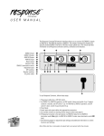
96 OUT
User Manual
96 OUT
The Response 96 Out interface allows you to convert 96 DMX512, AMX192, D192, or K96
dimmer signals to analog signals. This manual provides information on all Response 96 Out
controls, connectors and indicators.
❶
...............
...............
...............
...............
❷
❸
❼
...............
...............
3
❶
❷
❸
❹
❺
❻
❼
❽
➒
❿
0
Analog outputs
Number switches
DMX512 termination switch
Indicator LEDs
Reset switch
Fuse
Power switch
Power connector
DMX512/AMX192/D192/K96 Input
DMX512/AMX192/D192/K96 Pass Thru
❹
❽
❺
➒
❻
❿
To use Response 96 OUT, follow these steps:
1. Remove cover, and set DIP switches to select desired operation mode (see page 4).
2. Return cover to Response 96 OUT housing.
3. Plug power cable into the power connector and a 120 VAC outlet, and turn power switch
On.
4. Insert input cable input into the connector. If necessary, insert output cable into the Pass
Thru connector.
5. Insert 36-pin analog dimmer cables in analog output connectors.
6. Set number switches to select starting analog dimmer output number (see page 2).
7. If Response 96 OUT is the last device in a DMX512, D192 or K96 data link, set DMX512
termination switch On (right). In AMX192 mode, leave DMX512 termination switch Off
(left).
8. Press [Reset] after all options are adjusted to desired settings.
See following pages for filter and potentiometer settings and additional information on
switch functions and settings.
Note: When data flow is interrupted, all outputs fade to zero percent after approximately four
minutes.
Caution: AC is exposed when cover is removed.
Response 96 Out User Manual • Page 3
Entering starting analog dimmer number
For
starting
Enter output
01
02
03
04
05
06
07
08
09
10
11
12
13
14
15
16
17
18
19
20
21
22
23
24
25
26
27
28
29
30
1
7
13
19
25
31
37
43
49
55
61
67
73
79
85
91
97
103
109
115
121
127
133
139
145
151
157
163
169
175
Enter
For
starting
output
31
32
33
34
35
36
37
38
39
40
41
42
43
44
45
46
47
48
49
50
51
52
53
54
55
56
57
58
59
60
181
187
193
199
205
211
217
223
229
235
241
247
253
259
265
271
277
283
289
295
301
307
313
319
325
331
337
343
349
355
Enter
For
starting
output
61
62
63
64
65
66
67
68
69
70
71
72
73
74
75
76
77
78
79
80
81
82
83
84
85
86
361
367
373
379
385
391
397
403
409
415
421
427
433
439
445
451
457
463
469
475
481
487
493
499
505
511
The rotary number switches allow you to set the dimmer number for the first analog
output. The remaining 95 analog outputs are consecutively numbered from the number
you enter.
Refer to the accompanying chart to determine number switch setting for the desired
starting analog output number. You must press [Reset] after entering a new address
setting.
Performing diagnostic tests
Five diagnostic tests are provided on the Response 96 Out; each is described below.
To run a test, follow these steps:
1. Enter the two-digit test number on the rotary number switches. See below for test
numbers and descriptions.
2. Press [Reset] to start test.
3. Adjust the rate at which the test runs by setting the right number switch between 0
and 9. Test pauses when switch is set to 0; test runs at its maximum rate when
switch is set to 1, and at its minimum rate when switch is set to 9.
4. To stop test, enter a valid two-digit starting dimmer number (01- 86) on the number
switches, and press Reset.
Chase
2
9
The Chase test flashes each of the 96 analog dimmers to full intensity in a chase
sequence. Set number switches to 92.
Fade All
3
9
The Fade All test simultaneously fades all analog dimmers to full intensity, and then
back down to zero intensity. Set number switches to 93.
Fade Chase
4
9
The Fade Chase test fades each of the 96 analog dimmers to full intensity, and then
back to zero intensity, in a chase sequence. Set number switches to 94.
Selected Output to Full
5
9
The Selected Output to Full test sets a selected analog dimmer output to full
intensity and holds it there. Set number switches to 95, and press [Reset]. Then enter
analog dimmer number (01- 96).
All to Percent
6
9
Page 4 • Response 96 Out User Manual
The All to Percent test sets all analog dimmer outputs to an intensity percentage you
specify and holds them there. Set number switches to 96, and press [Reset]. Then
enter a percentage between 00 and 99 on the number switches.
Input connectors
1
Response 96 Out has two 5-pin XLR connectors, a male connector for input and a
female connector for pass through. The Pass Thru port allows you to pass the control
signal through the Response 96 Out to other interface or dimming equipment.
Pass Thru
Input
1
DMX512/D192/K96 connector pinout
1 - Common
2 - Data (–)
3 - Data (+)
4 - No connection
5 - Pass through
AMX192 connector pinout
1 - Common
2 - Clock (+)
3 - Clock (–)
4 - Analog multiplex
5 - Pass through
Reset switch
Pressing the [Reset] switch forces the microprocessor to reread DIP switch and
number switch settings.
You must press [Reset] to activate DIP switch setting changes and to start and stop
diagnostic tests.
Indicator LEDs
–15V
+15V
+5V
Data
Status
–15V LED continuous
+15V LED continuous
+5V LED continuous
Data LED continuous
Data LED blinking
Indicates
–15 volts power present
+15 volts power present
+5 volts power present
Valid data
No data
DMX512 termination switch
Off
On
If the Response 96 Out is the last device in a DMX512, D192 or K96 data stream, set
the DMX512 termination switch On (right) . If you are sending a digital data stream to
another interface or dimming device, set the DMX512 termination switch Off (left). For
AMX192 operation, set DMX512 termination switch Off (left).
Response 96 Out User Manual • Page 5
Potentiometers
The Response 96 Out has three potentiometers, two analog output pots, and an
AMX192 input pot. Pots are located on the circuit board inside the Response 96 Out.
Caution: AC is exposed when cover is removed.
AMX192 maximum input level (P1)
Pot P1 adjusts the maximum AMX192 input level. Voltage meter readings are required
to accurately adjust levels. Turn pot clockwise to decrease the maximum AMX192
input level, or counterclockwise to increase the maximum AMX192 input level. When
shipped from the factory, maximum AMX192 input level is set to 5 volts.
Maximum analog output level (P2)
Pot P2 adjusts the maximum analog output level from 0 to 12 volts. Voltage meter
readings are required to accurately adjust the output levels. When shipped from the
factory, maximum analog output level is set to 10 volts. Turn pot clockwise to increase
maximum analog output level or counterclockwise to decrease the maximum analog
output level.
P1
P3
P2
Minimum analog output level (P3)
Pot P3 adjusts the minimum analog output level from 0 to 300 millivolts. Voltage
meter readings are required to accurately adjust the output levels. When shipped from
the factory, minimum analog output level is set to 0 volts. Turn pot clockwise to
increase minimum analog output level or counterclockwise to decrease the minimum
analog output level. Note that minimum analog output setting (P3) affects the
maximum analog output setting (P2). Check both settings if you change either of them.
DIP switch settings
DIP switch settings determine operation mode and select analog output filters. See
below for DIP switch settings; set all unused DIP switches in the open position. DIP
switches are located on the circuit board inside the Response 96 Out.
Caution: AC is exposed when cover is removed.
Operation mode
Set DIP switches 1 and 2 according to chart below to select operation mode. System
is configured for DMX512 input when shipped from factory.
1
2
3
4
5
6
7
8
12
OPEN
DMX512 operation
AMX192 operation
D192 operation
K96 operation
Switch 1
Open
Open
Closed
Closed
Switch 2
Open
Closed
Open
Closed
Analog output filters
Output filters moderate fluctuating input signals. Filters slow lamp response to control
adjustments; therefore, experiment with filters to determine the minimum filter
needed. Set DIP switches 7 and 8 as shown below to select filter. System is configured with no filter when shipped from the factory.
78
No filter
Small filter
Medium filter
Large filter
Page 6 • Response 96 Out User Manual
Switch 7
Open
Closed
Open
Closed
Switch 8
Open
Open
Closed
Closed
Analog connectors
19
36
...............
...............
1
18
Three analog Centronics-type connectors each output 32 analog signals. Each analog
output can drive 10ma, with a maximum output of 250ma for the entire board. The
minimum voltage can be adjusted from 0 to 300 millivolts. The maximum voltage can
be adjusted from 0 to 12 volts. See the section on potentiometers for adjustment
information.
Analog pinouts
Connector 1
Pins 1-32 - Dimmers 1-32
Connector 2
Pins 1-32 - Dimmers 33-64
Connector 3
Pins 1-32 - Dimmers 65-96
All Connectors
Pins 33-34 - Not connected
Pins 35-36 - Common
Optical isolation
The Response 96 Out features an optical isolation device. Optical isolation creates a
physical break between the Response 96 Out and the DMX512 data link to help
prevent accidental high-voltage potentials applied to the analog outputs from
damaging other equipment on the DMX512 line.
If you are using the Response 96 Out in AMX192 operation mode (see page 6) you
must configure the circuit board to bypass the optical isolation feature.
A
AMX192 input
All other protocols
To bypass optical isolation for AMX192 operation, position jumper over both pins
at location A on circuit board (near 96-pin DIN connector).
To enable optical isolation for DMX512, D192 or K96 operation, position jumper
over only one pin at location A on circuit board.
AC power
The Response 96 Out has an operating range of 90 to 140 volts AC, 50/60 hertz with
nominal voltage at 115 volts. It has an external AGC-1 (one amp) fuse. Disconnect
power before replacing fuse. Consult factory on 240 VAC operation.
Specifications
Dimensions
Weight
Processing speed
2.1"H x 9"W x 16.75"D (portable)
1.75"H x 19"W x 15"D (rack mount)
7.75 pounds (portable)
12 pounds (rack mount)
50 hertz
Caution: AC is exposed when cover is removed.
Response 96 Out User Manual • Page 7
Electronic Theatre Controls
North America 3030 Laura Lane • Middleton, Wisconsin 53562 • USA • Tel: (+1) 608 831 4116 • Fax: (+1) 608 836 1736
Europe 5 Victoria Industrial Estate • Victoria Road • London W3 6UU • Tel: (+44) 181 896 1000 • Fax: (+44) 181 896 2000
Asia Room 1619-20 • 16/F Metro Centre II • 21 Lam Hing Street • Kowloon Bay • Hong Kong • Tel: (+852) 2799 1220 • Fax: (+852) 2799 9325
World Wide Web http://www.etcconnect.com • Email [email protected]
Copyright 1990-96. Specifications subject to change. 1086M1003. Revised 10/96