1
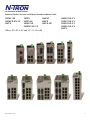
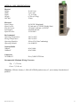
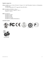
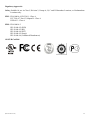
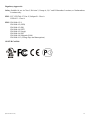
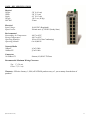
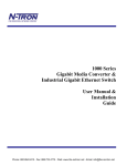
100 Series Media Converter & Industrial Ethernet Switches User Manual & Installation Guide (Revised 2011-04-15) 1 Industrial Media Converter and Ethernet Switch Installation Guide 102MC-XX 102MCE-XX-YY 104TX 105TX 105TX-SL 105FX-XX 105FXE-XX-YY 106FX2 108TX 108TX-HV 110FX2-XX-YY 111FX3-XX-YY 112FX4-XX-YY 114FX6-XX-YY 116TX Where: XX=ST or SC and YY= 15, 40 or 80 (Revised 2011-04-15) 2 Copyright, © N-TRON Corp., 2011 820 S. University Blvd., Suite 4E Mobile, AL USA 36609 All rights reserved. Reproduction, adaptation, or translation without prior written permission from N-TRON Corp. is prohibited, except as allowed under copyright laws. Ethernet is a registered trademark of Xerox Corporation. All other product names, company names, logos or other designations mentioned herein are trademarks of their respective owners. The information contained in this document is subject to change without notice. N-TRON Corp. makes no warranty of any kind with regard to this material, including, but not limited to, the implied warranties of merchantability or fitness for a particular purpose. In no event shall N-TRON Corp. be liable for any incidental, special, indirect or consequential damages whatsoever included but not limited to lost profits arising out of errors or omissions in this manual or the information contained herein. Contact Information N-TRON Corp. 820 South University Blvd. Suite 4E Mobile, AL 36609 TEL: (251) 342-2164 FAX: (251) 342-6353 Website: www.n-tron.com Email: [email protected] (Revised 2011-04-15) 3 GENERAL SAFETY WARNINGS WARNING: Do not operate the equipment in the presence of flammable gasses or fumes. Operating electrical equipment in such an environment constitutes a definite safety hazard. WARNING: If the equipment is used in the manner not specified by N-TRON Corp., the protection provided by the equipment may be impaired. WARNING: Do not perform any services on the unit unless qualified to do so. Do not substitute unauthorized parts or make unauthorized modifications to the unit. WARNING: hazard. Do not operate the unit with the end plates removed, as this could create a shock or fire WARNING: Properly ground the unit before connecting anything else to the unit. Units not properly grounded may result in a safety risk and could be hazardous and may void the warranty. See the grounding technique section of this user manual for proper ways to ground the unit. WARNING: Do not operate the equipment in a manner not specified by this manual. ENVIRONMENTAL SAFETY WARNINGS WARNING: Disconnect the power and allow to cool 5 minutes before touching. ELECTRICAL SAFETY WARNINGS WARNING: Disconnect the power cable before removing the end plates. WARNING: Do not operate the unit with the end plates removed. WARNING: Do not work on equipment or cables during periods of lightning activity. WARNING: Do not perform any services on the unit unless qualified to do so. WARNING: Observe proper DC Voltage polarity when installing power input cables. Reversing voltage polarity can cause permanent damage to the unit and void the warranty. (Revised 2011-04-15) 4 HAZARDOUS LOCATION INSTALLATION REQUIREMENTS 1. This equipment is suitable for use in Class I, Div 2, Groups A, B, C, and D hazardous locations, or unclassified or non-hazardous locations only. 2. WARNING: Explosion Hazard - Substitution of any component may impair suitability for Class I, Division 2. 3. WARNING: Explosion hazard, do not disconnect while the circuit is live or unless the area is known to be non-hazardous and to be free of ignitable concentrations. 4. WARNING: Explosion Hazard - Do not remove or replace the device unless power has been switched off or the area is known to be non-hazardous. 5. For 102MC, 105FX, 106FX and 108TX: Use 60/75ºC rated copper wire, (0.22Nm) 2 inch-lbs. tightening torque for field installed connectors. For 104TX, 105TX and 105TX-SL: Use 95°C rated copper wire, (0.22Nm) 2 inch-lbs. tightening torque for field installed conductors. For the 116TX: Use 105°C rated copper wire (0.22Nm) 2 inch-lbs. tightening torque for field installed conductors. 6. WARNING: Install only in accordance with Local & National Codes of Authorities Having Jurisdiction. 7. Class I, Div 2 Installations require that power connections must be current-limited at the power source with an in-line fuse rated at 0.5A. 8. Class I, Div 2 installations require that all devices connected to this product must be UL listed for the area in which it is installed. 9. All circuits must have a common disconnect and be connected to the same pole of the disconnect. 10. Limited Operating Voltage: 12-30V for Class I, Div 2 installations. 11. WARNING: For Sealed Relay Device a. Exposure to some chemicals may degrade the sealing properties of materials used in the sealed relay device. b. Recommendation: It is recommended to inspect the sealed relay device periodically and to check for any degradation of the materials and to replace the complete product, not the sealed device, if any degradation is found. (Revised 2011-04-15) 5 100 Series Industrial Ethernet Switches The 100 Series Unmanaged Industrial Ethernet Switches support high speed layer 2 switching between ports. This series of switches are housed in a ruggedized aluminum enclosure, and provide Category-5 compliant 10/100-BaseT connections for high performance network design, and hub/repeater upgrades. All fiber products utilize the IEEE compliant SC or ST duplex connectors for fiber optic communications. All 10/100Base-TX ports utilize the RJ45 shielded connectors. The 102MC/MCE is a two-port unmanaged media converter that converts 10/100BaseTX copper to 100BaseFX full duplex fiber. The 104TX, 105TX and 108TX are affordable and share a small footprint. Each switch is capable of auto negotiating 10/100 Mb and half/full duplex communications. The five-port 105TX-SL offers the same functionality and is distinguished by its ultra-slim enclosure. The 105FX/FXE has 4 ports similar to the 104TX, plus additional multimode fiber optic up-link port(s), capable of 2 Kilometers of 100 Mb communications for the FX models, and up to 80 Kilometers for the FXE models without the use of repeaters. The 106FX2/FXE2 has 4 10/100BaseTX RJ-45 auto sensing ports and 2 100BaseFX ports with ST or SC connectors, capable of 2 Kilometers of 100 Mb communications for the FX models, and up to 80 Kilometers for the FXE models without the use of repeaters. The 110FX2/FXE2 has 8 10/100BaseTX RJ-45 auto sensing ports and 2 100BaseFX ports with ST or SC connectors, capable of 2 Kilometers of 100 Mb communications for the FX models, and up to 80 Kilometers for the FXE models without the use of repeaters. The 111FX3/FXE3 has 8 10/100BaseTX RJ-45 auto sensing ports and 3 100BaseFX ports with ST or SC connectors, capable of 2 Kilometers of 100 Mb communications for the FX models, and up to 80 Kilometers for the FXE models without the use of repeaters. The 112FX4/FXE4 has 8 10/100BaseTX RJ-45 auto sensing ports and 4 100BaseFX ports with ST or SC connectors, capable of 2 Kilometers of 100 Mb communications for the FX models, and up to 80 Kilometers for the FXE models without the use of repeaters. The 114FX6/FXE6 has 8 10/100BaseTX RJ-45 auto sensing ports and 6 100BaseFX ports with ST or SC connectors, capable of 2 Kilometers of 100 Mb communications for the FX models, and up to 80 Kilometers for the FXE models without the use of repeaters. The 116TX has 16 10/100BaseTX RJ-45 auto sensing. Each port is capable of auto negotiating 10/100 Mb and half/full duplex communications. Key Features Full IEEE 802.3 & 100Base-FX Compliance Extended Environmental Specifications Support for Full/Half Duplex Operation LED Link/Activity Status Indication Autonegotiation, Autosensing Speed, Duplex, and Flow Control Up to 3.2 Gb/s Maximum Throughput Industry Standard 35mm DIN Rail Mounted Enclosure (Revised 2011-04-15) 6 PACKAGE CONTENTS Please make sure the package contains the following items: 1. 2. 100 Series Media Converter or Ethernet Switch Instruction Sheet Contact your carrier if any items are damaged. UNPACKING Remove all the equipment from the packaging, and store the packaging in a safe place. File any damage claims with the carrier. CLEANING Clean only with a damp cloth. INSTALLATION Read the following warning before beginning the installation: WARNING Never install or work on electrical equipment or cabling during periods of lightning activity. Never connect or disconnect power when hazardous gasses are present. LASER SAFETY (MCE and FXE models only -40 and -80) CAUTION: CLASS 1 LASER PRODUCT. Do not stare into the laser! (Revised 2011-04-15) 7 DIN-Rail Mounting Install the unit in a standard DIN rail. Recess the unit to allow at least 2” of horizontal clearance for CAT5e cable bend radius. To install the plastic clip units to 35mm industrial DIN rail, place the top edge of the included mounting bracket on the back of the unit against the DIN rail at a 15° angle as shown. Rotate the bottom of the unit to the back (away from you) until it snaps into place. To remove the plastic clip units from the 35mm industrial DIN rail, place a flat head screwdriver into the release clip found at the bottom of the unit, and apply downward force on the clip until it disengages from the bottom of the unit from the DIN rail. Rotate the bottom of the unit towards you and up at an approximate 15° upward angle to completely remove the unit. To install the metal clip units to 35mm industrial DIN rail, place the top edge of the included mounting bracket on the back of the unit against the DIN rail at a 15° angle as shown. Rotate the bottom of the unit to the back (away from you) until it snaps into place. To remove the metal clip units from the 35mm industrial DIN rail, pull forward on the unit until it disengages from the bottom of the DIN rail. Rotate the bottom of the unit towards you and up at an approximate 15° upward angle to completely remove the unit. (Revised 2011-04-15) 8 URMK 1000-PM Most N-Tron™ products are designed to be mounted on industry standard 35mm DIN rail. However, DIN rail mounting may not be suitable for all applications. Our Universal Rack Mount Kit (P/N: URMK) may be used to mount the 100 Series enclosures to standard 19" racks, and our Panel Mount Assembly (P/N: 1000-PM) may be used to mount the metal clip versions of the 100 Series enclosures to a panel or any other flat surface. NOTE: the 1000-PM will only work with the factory installed –MDR metal clip options and it is not acceptable for the 116TX units. (Revised 2011-04-15) 9 FRONT PANEL From Top to Bottom: SPD LNK/ACT RJ45 Ports Speed LED Link/Activity LED Auto sensing 10/100BaseT Connection Green LED lights when Power is connected NOTE: The top LED indicates Link/Activity (LNK/ACT), and the lower LED indicates Speed (SPD) status. (Revised 2011-03-14) 10 LED’s: The table below describes the operating modes: LED LNK/ACT Color Description ON Power is Applied. OFF Power is OFF. ON Link established, no Activity on cable. BLINKING Link established, Activity on cable OFF No link activity on cable. ON LINK is 100Mbps. OFF Link is 10Mbs. SPD APPLYING POWER • 102MC, 104TX, 105TX, 105FX, 106FX2, 108TX, and 116TX Power Connector (Top View) (Revised 2011-03-14) 11 • 110FX2, 111FX3, 112FX4, and 114FX6 Power Connector (Top View) (must be powered by Class 2 source only) Unscrew & Remove the DC Voltage Input Plug from the top header. Install the DC Power Cables into the Plug (observing polarity on unit). Plug the Voltage Input Plug back into the top header. Tightening torque for the terminal block power plug is 0.22 Nm/0.162 Pound Foot. All LED’s will flash ON Momentarily. Verify the Power LED stays ON (GREEN). Note: Either V1 or V2 can be connected to power for minimal operation. For redundant power operation, V1 and V2 plugs must be connected to separate DC Voltage sources. Use wire sizes of 16-28 gauge. The power cord should be limited to less than 10 meters in order to ensure optimum performance. Recommended 24V DC Power Supplies, similar to: 100-240VAC: N-Tron NTPS-24-1.3, DC 24V/1.3 • 105TX-SL (Top View) Unscrew & Remove the DC Voltage Input Plug from the top header. Install the DC Power Cables into the Plug (observing polarity on unit). Plug the Voltage Input Plug back into the top header. Tightening torque for the terminal block power plug is 0.5 Nm/0.368 Pound Foot. (Revised 2011-03-14) 12 All LEDs will flash ON Momentarily. Verify the Power LED stays ON (GREEN). Note: Either V1 or V2 can be connected to power for minimal operation. For redundant power operation, V1 and V2 plugs must be connected to separate DC Voltage sources. Use wire sizes of 12-28 gauge. The power cord should be limited to less than 10 meters in order to ensure optimum performance. Recommended 24V DC Power Supplies, similar to: 100-240VAC: N-Tron NTPS-24-1.3, DC 24V/1.3A N-TRON SWITCH GROUNDING TECHNIQUES FOR 100 SERIES 102MC, 104TX, 105TX, 105FX, 106FX2 and 108TX The grounding philosophy of any control system is an integral part of the design. N-Tron switches are designed to be grounded, but the user has been given the flexibility to float the switch when required. The best noise immunity and emissions (i.e. CE) are obtained when the N-Tron switch chassis is connected to earth ground via a drain wire. Some N-Tron switches have metal din-rail brackets that can ground the switch if the din-rail is grounded. In some cases, N-Tron switches with metal brackets can be supplied with optional plastic brackets if isolation is required. Users may run a drain wire & lug from the screw provided on the back face of the enclosure. In the event the provided grounding screw has been lost, care should be taken to limit the penetration of the outer skin by less than 1/4". Failure to do so may cause irreversible damage to the internal components of the switch. Note: Ensure the power supply is grounded properly before applying power to the grounded switch. This may be verified by using a voltmeter to determine that there is no voltage difference between the power supply’s negative output terminal and the chassis grounding point of the switch. 110FX2, 111FX3, 112FX4, 114FX6 and 116TX As an alternative grounding method, both V- legs of the power input connector are connected to chassis internally on the PCB. Connecting a drain wire to earth ground from one of the V- terminal plugs as shown here will ground the switch and the chassis. The power leads from the power source should be limited to 3 meters or less in length. If the use of shielded cables is required, it is generally recommended to only connect the shield at one end to prevent ground loops and interfere with low level signals (i.e. thermocouples, RTD, etc.). Cat5e cables manufactured to EIA-568A or 568B specifications are required for use with N-Tron Switches. (Revised 2011-03-14) DRAIN WIRE WITH LUG CONNECTING SWITCH CHASSIS TO KNOWN GOOD GROUNDING POINT 13 105TX-SL METALLIC DIN-RAIL CLIP DRAIN WIRE WITH LUG CONNECTING SWITCH CHASSIS TO KNOWN GOOD GROUNDING POINT. DRAIN WIRE WITH LUG CONNECTING SWITCH CHASSIS TO KNOWN GOOD GROUNDING POINT. In the event all Cat5e patch cable distances are small (i.e. All Ethernet devices are located the same local cabinet and/or referenced to the same earth ground), it is permissible to use fully shielded cables terminated to chassis ground at both ends in systems void of low level analog signals. RJ45 CONNECTOR CRIMP SPECIFICATIONS Please reference the illustration for your Cat5 cable specifications. (Revised 2011-03-14) 14 CONNECTING THE UNIT For FX/FXE units, remove the dust cap from the fiber optic connectors and connect the fiber optic cables. The TX port (located on the bottom connector) on the FX/FXE models should be connected to the RX port of the far end station. The RX port (located on the top connector) on the FX/FXE versions should be connected to the TX port of the far end station. For 10Base-T ports, plug a Category 3 (or greater) twisted pair cable into the RJ45 connector. For 100Base-T ports, plug a Category 5 (or greater) twisted pair cable into the RJ45 connector. Connect the other end to the far end station. Verify that the LNK LED’s are ON once the connection has been completed. To connect any other port to another Switch or Repeater, use a standard Cat5 straight through or crossover cable. Warning: Creating a port to port connection on the same switch (i.e. loop) is an illegal operation and will create a broadcast storm which will crash the network! TROUBLESHOOTING 1. Make sure the (Power LED) is ON. 2. Make sure you are supplying sufficient current for the version chosen. Note: The Inrush current will exceed the steady state current by ~ 2X. 3. Verify that Link LED’s are ON for connected ports. 4. Verify cabling used between stations. 5. Verify that cabling is Category 3 or greater for 10Mbit Operation. SUPPORT Contact N-Tron Corporation at: TEL: 251-342-2164 FAX: 251-342-6353 www.n-tron.com [email protected] (Revised 2011-03-14) 15 FCC STATEMENT This product complies with Part 15 of the FCC-A Rules. Operation is subject to the following conditions: (1) This device may not cause harmful Interference (2) This device must accept any interference received, including interference that may cause undesired operation. NOTE: This equipment has been tested and found to comply with the limits for a Class A digital device, pursuant to Part 15 of the FCC Rules. These limits are designed to provide reasonable protection against harmful interference in a residential installation. This equipment generates, uses, and can radiate radio frequency energy and, if not installed and used in accordance with the instructions, may cause harmful interference to radio communications. Operation of this device in a residential area is likely to cause harmful interference in which case the user will be required to correct the interference at his/her own expense. INDUSTRY CANADA This Class A digital apparatus meets all requirements of the Canadian Interference Causing Equipment Regulations. Operation is subject to the following two conditions; (1) this device may not cause harmful interference, and (2) this device must accept any interference received, including interference that may cause undesired operation. Cet appareillage numérique de la classe A répond à toutes les exigences de l'interférence canadienne causant des règlements d'équipement. L'opération est sujette aux deux conditions suivantes: (1) ce dispositif peut ne pas causer l'interférence nocive, et (2) ce dispositif doit accepter n'importe quelle interférence reçue, y compris l'interférence qui peut causer l'opération peu désirée. (Revised 2011-03-14) 16 102MC/MCE - KEY SPECIFICATIONS Physical Height: Width: Depth: Weight: DIN Rail 2.87” (7.28 cm) 1.49” (3.78 cm) 3.53” (8.96 cm) 0.5 lbs. (0.22 kg) 35 mm Electrical Input Voltage: Input Current: Inrush Current: Input Ripple: Input Wire Size: 10-30 VDC (Regulated) 140mA max. @ 24VDC (Steady State) 8.5 Amp/0.7 ms max. @ 24VDC Less than 100 mV 16-28 AWG Environmental Operating Temperature: Storage Temperature: Operating Humidity: Operating Altitude: -40°C to 80°C -40°C to 85°C 10% to 95% (Non Condensing) 0 to 10,000 ft. Network Media 10BaseT: 100BaseT: 100BaseFX: > Cat-3 Cable > Cat-5 Cable Multimode: 50-62.5/125µm Fiber Singlemode: 7-10/125µm Fiber Fiber Transceiver Characteristics Fiber Length: 2km* 15km** 40km** TX Power Min -19dBm -15dBm -5dBm 80km** -5dBm RX Sensitivity Max: -31dBm -31dBm -34dBm -34dBm Wavelength: 1310nm 1310nm 1310nm *=Multimode ** =Singlemode 1550nm Connectors 10/100BaseTX: 100BaseFX: RJ45 UTP Port SC or ST Duplex Port Recommended Minimum Wiring Clearance: Top: 1 " (2.54 cm) Front: 4 " (10.16 cm) Warranty: Effective January 1, 2008, all N-TRON products carry a 3 year warranty from the date of purchase. (Revised 2011-03-14) 17 Regulatory Approvals: Safety: Suitable for use in Class I, Division 2, Groups A, B, C and D Hazardous Locations, or Nonhazardous Locations only. EMI: EN61000-6-4, EN55011 - Class A FCC Title 47, Part 15, Subpart B - Class A ICES-003 – Class A EMS: EN61000-6-2 EN61000-4-2 (ESD) EN61000-4-3 (RS) EN61000-4-4 (EFT) EN61000-4-5 (Surge) EN61000-4-6 (Conducted Disturbances) GOST-R Certified. (Revised 2011-03-14) 18 104TX/105TX - KEY SPECIFICATIONS Physical Height: Width: Depth: Weight: DIN Rail 2.87” (7.28 cm) 1.49” (3.78 cm) 3.53” (8.96 cm) 0.6 lbs. (0.27 kg) 35 mm Electrical Input Voltage: Input Current: Inrush Current: Input Ripple: Input Wire Size: 10-30 VDC (Regulated) 215 mA max. @ 24VDC (Steady State) 7.8 Amp/0.7ms max. @ 24VDC Less than 100 mV 16-28 AWG Environmental Operating Temperature: Storage Temperature: Operating Humidity: Operating Altitude: -40°C to 80°C -40°C to 85°C 10% to 95% (Non Condensing) 0 to 10,000 ft. Network Media 10BaseT: 100BaseT: > Cat-3 Cable > Cat-5 Cable Connectors 10/100BaseT: RJ45 UTP Ports Recommended Minimum Wiring Clearance: Top: 1 " (2.54 cm) Front: 2 " (5.08 cm) Warranty: Effective January 1, 2008, all N-TRON products carry a 3 year warranty from the date of purchase. (Revised 2011-03-14) 19 Regulatory Approvals: Safety: Suitable for use in Class I, Division 2, Groups A, B, C and D Hazardous Locations, or Nonhazardous Locations only. EMI: EN61000-6-4, EN55011 - Class A FCC Title 47, Part 15, Subpart B - Class A ICES-003 – Class A EMS: EN61000-6-2 EN61000-4-2 (ESD) EN61000-4-3 (RS) EN61000-4-4 (EFT) EN61000-4-5 (Surge) EN61000-4-6 (Conducted Disturbances) GOST-R Certified. (Revised 2011-03-14) 20 105TX-SL - KEY SPECIFICATIONS Physical Height: Width: Depth: Weight: DIN Rail 4″ (10.2 cm) 1″ (2.6 cm) 3.7″ (9.2 cm) 0.7 lbs. (0.32 kg) 35 mm Electrical Input Voltage: Input Current: Inrush Current: Input Ripple: Input Wire Size: 10-30 VDC (Regulated) 215 mA max. @ 24VDC (Steady State) 3.0 Amp/1.0 ms max. @ 24VDC Less than 100 mV 12-24 AWG Environmental Operating Temperature: Storage Temperature: Operating Humidity: Operating Altitude: -40°C to 85°C -40°C to 85°C 10% to 95% (Non Condensing) 0 to 10,000 ft. Network Media 10BaseT: 100BaseT: Connectors 10/100BaseT: ≥Cat3 Cable ≥Cat5 Cable Five (5) RJ45 UTP Ports Recommended Minimum Wiring Clearance: Top: 1" (2.54 cm) Front: 2" (5.08 cm) Warranty: Effective January 1, 2008, all N-TRON products carry a 3 year warranty from the date of purchase. (Revised 2011-03-14) 21 Regulatory Approvals: Safety: Suitable for use in Class I, Division 2, Groups A, B, C and D Hazardous Locations, or Nonhazardous Locations only. EMI: ANSI C63.4 FCC Title 47, Part 15, Subpart B - Class A ICES-003 – Class A EMC: EN61000-6-4 – Class A (Emissions) EN55024 (Immunity) EN61000-4-2 (ESD) EN61000-4-3 (RS) EN61000-4-4 (EFT) EN61000-4-5 (SURGE) EN61000-4-6 (RF) EN61000-4-8 (PFMF) EN61000-4-11 (VDI) GOST-R Certified. (Revised 2011-03-14) 22 106FX/FX2 - KEY SPECIFICATIONS Physical Height: Width: Depth: Weight: DIN Rail 3.83” (9.73 cm) 1.50” (3.81 cm) 4.80” (12.2 cm) 0.6 lbs. (0.27 kg) 35 mm Electrical Input Voltage: Input Current: Inrush Current: 10-30 VDC (Regulated) 270 mA max. @ 24VDC (Steady State) 8.0 Amp/0.7 ms max. @ 24VDC Environmental Operating Temperature: Storage Temperature: Operating Humidity: Operating Altitude: -40°C to 70°C -40°C to 85°C 10% to 95% (Non Condensing) 0 to 10,000 ft. Network Media 10BaseT: 100BaseTX: 100BaseFX: Multimode: Singlemode: Connectors 10/100BaseTX 100BaseFX > Cat-3 Cable > Cat-5 Cable 50-62.5/125µm 7-10/125µm Four (4) RJ-45 TX Ports Two (2) ST or SC Duplex Ports Recommended Minimum Wiring Clearance: Top: 1 " (2.54 cm) Front: 4 " (10.16 cm) Warranty: Effective January 1, 2008, all N-TRON products carry a 3 year warranty from the date of purchase. (Revised 2011-03-14) 23 Regulatory Approvals: Safety: Suitable for use in Class I, Division 2, Groups A, B, C and D Hazardous Locations, or Nonhazardous Locations only. EMI: IEC61000-6-2, EN55011 - Class A FCC Title 47, Part 15, Subpart B - Class A ICES-003 – Class A EMS: EN61000-6-2 EN61000-4-2 (ESD) EN61000-4-3 (RS) EN61000-4-4 (EFT) EN61000-4-5 (Surge) EN61000-4-6 (Conducted Disturbances) EN61000-4-11 (Voltage Dips and Interruptions) GOST-R Certified. (Revised 2011-03-14) 24 108TX - KEY SPECIFICATIONS Physical Height: Width: Depth: Weight: DIN Rail 3.5” (8.89 cm) 1.49” (3.78 cm) 3.53” (8.96 cm) 0.7 lbs. (0.31 kg) 35 mm Electrical Input Voltage: -HV option: Input Current: Inrush Current: Input Ripple: Input Wire Size: 10-30 VDC (Regulated) 10-60 VDC (Regulated) 250 mA max. @ 24VDC (Steady State) 8.1 Amp/0.7 ms max. @ 24VDC Less than 100 mV 16-28 AWG Environmental Operating Temperature: Storage Temperature: Operating Humidity: Operating Altitude: -40°C to 70°C -40°C to 85°C 10% to 95% (Non Condensing) 0 to 10,000 ft. Network Media 10BaseT: 100BaseT: > Cat-3 Cable > Cat-5 Cable Connectors 10/100BaseT: Eight (8) RJ45 UTP Ports Recommended Minimum Wiring Clearance: Top: 1 " (2.54 cm) Front: 2 " (5.08 cm) Warranty: Effective January 1, 2008, all N-TRON products carry a 3 year warranty from the date of purchase. (Revised 2011-03-14) 25 Regulatory Approvals: Safety: Suitable for use in Class I, Division 2, Groups A, B, C and D Hazardous Locations, or Nonhazardous Locations only. The high voltage model is TÜV approved GS per EN 60950-1. EMI: EN61000-6-4, EN55011 - Class A FCC Title 47, Part 15, Subpart B - Class A ICES-003 – Class A EMS: EN61000-6-2 EN61000-4-2 (ESD) EN61000-4-3 (RS) EN61000-4-4 (EFT) EN61000-4-5 (Surge) EN61000-4-6 (Conducted Disturbances) GOST-R Certified. HV Model Only (Revised 2011-03-14) 26 105FX - KEY SPECIFICATIONS Physical Height: Width: Depth: Weight: DIN Rail 3.83” (9.72 cm) 1.49” (3.78 cm) 3.53” (8.96 cm) 0.6 lbs. (0.27 kg) 35 mm Electrical Input Voltage: Input Current: Inrush Current: Input Ripple: Input Wire Size: 10-30 VDC (Regulated) 270mA max. @ 24VDC (Steady State) 8.0 Amp/0.7 ms max. @ 24VDC Less than 100 mV 16-28 AWG Environmental Operating Temperature: Storage Temperature: Operating Humidity: Operating Altitude: -40°C to 70°C -40°C to 85°C 10% to 95% (Non Condensing) 0 to 10,000 ft. Network Media 10BaseT: 100BaseT: 100BaseFX: > Cat-3 Cable > Cat-5 Cable Multimode: 50-62.5/125µm Fiber Singlemode: 7-10/125µm Fiber Fiber Transceiver Characteristics Fiber Length: 2km* 15km** 40km** TX Power Min -19dBm -15dBm -5dBm 80km** -5dBm RX Sensitivity Max: -31dBm -31dBm -34dBm -34dBm Wavelength: 1310nm 1310nm 1310nm *=Multimode ** =Singlemode 1550nm Connectors 10/100BaseTX: 100BaseFX: RJ45 UTP Port SC or ST Duplex Port Recommended Minimum Wiring Clearance: Top: 1 " (2.54 cm) Front: 4 " (10.16 cm) Warranty: Effective January 1, 2008, all N-TRON products carry a 3 year warranty from the date of purchase. (Revised 2011-03-14) 27 Regulatory Approvals: Safety: Suitable for use in Class I, Division 2, Groups A, B, C and D Hazardous Locations, or Nonhazardous Locations only. EMI: EN 61000-6-4, EN 55011 - Class A FCC Title 47, Part 15, Subpart B - Class A ICES-003 – Class A EMS: EN 61000-6-2 IEC 61000-4-2 (ESD) IEC 61000-4-3 (RS) IEC 61000-4-4 (EFT) IEC 61000-4-5 (Surge) IEC 61000-4-6 (Conducted Disturbances) GOST-R Certified. (Revised 2011-03-14) 28 110FX2 - KEY SPECIFICATIONS Physical Height: Width: Depth: Weight: DIN Rail 4.3” (10.8 cm) 2.4” (6.1 cm) 4.6” (11.5 cm) 1 lbs. 5 oz (0.60 kg) 35 mm Electrical Input Voltage: Input Current: 10-49 VDC (Regulated) 355 mA max. @ 24VDC (Steady State) Environmental Surrounding Air Temperature: Storage Temperature: Operating Humidity: Operating Altitude: -40°C to 80°C -40°C to 85°C 10% to 95% (Non Condensing) 0 to 10,000 ft. Network Media 10BaseT: 100BaseTX: 100BaseFX: Multimode: Singlemode: Connectors 10/100BaseTX 100BaseFX > Cat-3 Cable > Cat-5 Cable 50-62.5/125µm 7-10/125µm Eight (8) RJ-45 TX Ports Two (2) ST or SC Duplex Ports Recommended Minimum Wiring Clearance: Top: 1 " (2.54 cm) Front: 4 " (10.16 cm) Warranty: Effective January 1, 2008, all N-TRON products carry a 3 year warranty from the date of purchase. (Revised 2011-03-14) 29 Regulatory Approvals: Safety: Suitable for use in Class I, Division 2, Groups A, B, C and D Hazardous Locations, or Nonhazardous Locations only. EMI: FCC CFR Title 47, Part 15, Subpart B - Class A ICES-003 – Class A EMC: EN61000-6-2/4 EN61000-4-2 (ESD) EN61000-4-3 (RS) EN61000-4-4 (EFT) EN61000-4-5 (Surge) EN61000-4-6 (RF) EN61000-4-8 (Magnetic Field) EN61000-4-11 (Voltage Dips and Interruptions) GOST-R Certified. (Revised 2011-03-14) 30 111FX3 - KEY SPECIFICATIONS Physical Height: Width: Depth: Weight: DIN Rail 4.3” (10.8 cm) 2.4” (6.1 cm) 4.6” (11.5 cm) 1 lbs. 5 oz (0.60 kg) 35 mm Electrical Input Voltage: Input Current: 10-49 VDC (Regulated) 410 mA max. @ 24VDC (Steady State) Environmental Surrounding Air Temperature: Storage Temperature: Operating Humidity: Operating Altitude: -40°C to 80°C -40°C to 85°C 10% to 95% (Non Condensing) 0 to 10,000 ft. Network Media 10BaseT: 100BaseTX: 100BaseFX: Multimode: Singlemode: Connectors 10/100BaseTX 100BaseFX > Cat-3 Cable > Cat-5 Cable 50-62.5/125µm 7-10/125µm Eight (8) RJ-45 TX Ports Two (2) ST or SC Duplex Ports Recommended Minimum Wiring Clearance: Top: 1 " (2.54 cm) Front: 4 " (10.16 cm) Warranty: Effective January 1, 2008, all N-TRON products carry a 3 year warranty from the date of purchase. (Revised 2011-03-14) 31 Regulatory Approvals: Safety: Suitable for use in Class I, Division 2, Groups A, B, C and D Hazardous Locations, or Nonhazardous Locations only. EMI: FCC CFR Title 47, Part 15, Subpart B - Class A ICES-003 – Class A EMC: EN61000-6-2/4 EN61000-4-2 (ESD) EN61000-4-3 (RS) EN61000-4-4 (EFT) EN61000-4-5 (Surge) EN61000-4-6 (RF) EN61000-4-8 (Magnetic Field) EN61000-4-11 (Voltage Dips and Interruptions) GOST-R Certified. (Revised 2011-03-14) 32 112FX4 - KEY SPECIFICATIONS Physical Height: Width: Depth: Weight: DIN Rail 4.3” (10.8 cm) 3.1” (7.9 cm) 4.6” (11.5 cm) 1 lbs. 9 oz (0.70 kg) 35 mm Electrical Input Voltage: Input Current: 10-49 VDC (Regulated) 455 mA max. @ 24VDC (Steady State) Environmental Surrounding Air Temperature: Storage Temperature: Operating Humidity: Operating Altitude: -40°C to 80°C -40°C to 85°C 10% to 95% (Non Condensing) 0 to 10,000 ft. Network Media 10BaseT: 100BaseTX: 100BaseFX: Multimode: Singlemode: Connectors 10/100BaseTX 100BaseFX > Cat-3 Cable > Cat-5 Cable 50-62.5/125µm 7-10/125µm Eight (8) RJ-45 TX Ports Four (4) ST or SC Duplex Ports Recommended Minimum Wiring Clearance: Top: 1 " (2.54 cm) Front: 4 " (10.16 cm) Warranty: Effective January 1, 2008, all N-TRON products carry a 3 year warranty from the date of purchase. (Revised 2011-03-14) 33 Regulatory Approvals: Safety: Suitable for use in Class I, Division 2, Groups A, B, C and D Hazardous Locations, or Nonhazardous Locations only. EMI: FCC CFR Title 47, Part 15, Subpart B - Class A ICES-003 – Class A EMC: EN61000-6-2/4 EN61000-4-2 (ESD) EN61000-4-3 (RS) EN61000-4-4 (EFT) EN61000-4-5 (Surge) EN61000-4-6 (RF) EN61000-4-8 (Magnetic Field) EN61000-4-11 (Voltage Dips and Interruptions) GOST-R Certified. (Revised 2011-03-14) 34 114FX6 - KEY SPECIFICATIONS Physical Height: Width: Depth: Weight: DIN Rail 4.3” (10.8 cm) 3.1” (7.9 cm) 4.6” (11.5 cm) 1 lbs. 10 oz (0.73 kg) 35 mm Electrical Input Voltage: Input Current: 10-49 VDC (Regulated) 545 mA max. @ 24VDC (Steady State) Environmental Surrounding Air Temperature: Storage Temperature: Operating Humidity: Operating Altitude: -40°C to 80°C -40°C to 85°C 10% to 95% (Non Condensing) 0 to 10,000 ft. Network Media 10BaseT: 100BaseTX: 100BaseFX: Multimode: Singlemode: Connectors 10/100BaseTX 100BaseFX > Cat-3 Cable > Cat-5 Cable 50-62.5/125µm 7-10/125µm Eight (8) RJ-45 TX Ports Four (4) ST or SC Duplex Ports Recommended Minimum Wiring Clearance: Top: 1 " (2.54 cm) Front: 4 " (10.16 cm) Warranty: Effective January 1, 2008, all N-TRON products carry a 3 year warranty from the date of purchase. (Revised 2011-03-14) 35 Regulatory Approvals: Safety: Suitable for use in Class I, Division 2, Groups A, B, C and D Hazardous Locations, or Nonhazardous Locations only. EMI: FCC CFR Title 47, Part 15, Subpart B - Class A ICES-003 – Class A EMC: EN61000-6-2/4 EN61000-4-2 (ESD) EN61000-4-3 (RS) EN61000-4-4 (EFT) EN61000-4-5 (Surge) EN61000-4-6 (RF) EN61000-4-8 (Magnetic Field) EN61000-4-11 (Voltage Dips and Interruptions) GOST-R Certified. (Revised 2011-03-14) 36 116TX - KEY SPECIFICATIONS Physical Height: Width: Depth: Weight: DIN Rail 5.8″ (14.6 cm) 2.0″ (5.1 cm) 4.1″ (10.3 cm) 1 lb. 1 oz (.48 kg) 35 mm Electrical Input Voltage: Input Current: 10-49 VDC (Regulated) 300 mA max. @ 24VDC (Steady State) Environmental Surrounding Air Temperature: Storage Temperature: Operating Humidity: Operating Altitude: -40°C to 85°C -40°C to 85°C 10% to 95% (Non Condensing) 0 to 10,000 ft. Network Media 10BaseT: 100BaseTX: ≥Cat3 Cable ≥Cat5 Cable Connectors 10/100BaseTX Sixteen (16) RJ-45 TX Ports Recommended Minimum Wiring Clearance: Top: 1" (2.6 cm) Front: 2" (5.1 cm) Warranty: Effective January 1, 2008, all N-TRON products carry a 3 year warranty from the date of purchase. (Revised 2011-03-14) 37 Regulatory Approvals: Safety: Suitable for use in Class I, Division 2, Groups A, B, C and D Hazardous Locations, or Nonhazardous Locations only. EMI: ANSI C63.4 FCC CFR Title 47, Part 15, Subpart B - Class A ICES-003 – Class A EMC: EN61000-6-4 – Class A (Emissions) EN 55024 (Immunity) EN61000-4-2 (ESD) EN61000-4-3 (RS) EN61000-4-4 (EFT) EN61000-4-5 (Surge) EN61000-4-6 (RF) EN61000-4-8 (PFMF) EN61000-4-11 (VDI) GOST-R Certified. (Revised 2011-03-14) 38 N-TRON Limited Warranty N-TRON, Corp. warrants to the end user that this hardware product will be free from defects in workmanship and materials, under normal use and service, for the applicable warranty period from the date of purchase from N-TRON or its authorized reseller. If a product does not operate as warranted during the applicable warranty period, N-TRON shall, at its option and expense, repair the defective product or part, deliver to customer an equivalent product or part to replace the defective item, or refund to customer the purchase price paid for the defective product. All products that are replaced will become the property of N-TRON. Replacement products may be new or reconditioned. Any replaced or repaired product or part has a ninety (90) day warranty or the remainder of the initial warranty period, whichever is longer. N-TRON shall not be responsible for any custom software or firmware, configuration information, or memory data of customer contained in, stored on, or integrated with any products returned to N-TRON pursuant to any warranty. OBTAINING WARRANTY SERVICE: Customer must contact N-TRON within the applicable warranty period to obtain warranty service authorization. Dated proof of purchase from N-TRON or its authorized reseller may be required. Products returned to N-TRON must be preauthorized by N-TRON with a Return Material Authorization (RMA) number marked on the outside of the package, and sent prepaid and packaged appropriately for safe shipment. Responsibility for loss or damage does not transfer to N-TRON until the returned item is received by N-TRON. The repaired or replaced item will be shipped to the customer, at N-TRON’s expense, not later than thirty (30) days after N-TRON receives the product. N-TRON shall not be responsible for any software, firmware, information, or memory date of customer contained in, stored on, or integrated with any products returned to N-TRON for repair, whether under warranty or not. ADVANCE REPLACEMENT OPTION: Upon registration, this product qualifies for advance replacement. A replacement product will be shipped within three (3) days after verification by N-TRON that the product is considered defective. The shipment of advance replacement products is subject to local legal requirements and may not be available in all locations. When an advance replacement is provided and customer fails to return the original product to N-TRON within fifteen (15) days after shipment of the replacement, N-TRON will charge customer for the replacement product, at list price. WARRANTIES EXCLUSIVE: IF AN N-TRON PRODUCT DOES NOT OPERATE AS WARRANTED ABOVE, CUSTOMER'S SOLE REMEDY FOR BREACH OF THAT WARRANTY SHALL BE REPAIR, REPLACEMENT, OR REFUND OF THE PURCHASE PRICE PAID, AT N-TRON'S OPTION. TO THE FULL EXTENT ALLOWED BY LAW, THE FOREGOING WARRANTIES AND REMEDIES ARE EXCLUSIVE AND ARE IN LIEU OF ALL OTHER WARRANTIES, TERMS, OR CONDITIONS, EXPRESS OR IMPLIED, EITHER IN FACT OR BY OPERATION OF LAW, STATUTORY OR OTHERWISE, INCLUDING WARRANTIES, TERMS, OR CONDITIONS OF MERCHANTABILITY, FITNESS FOR A PARTICULAR PURPOSE, SATISFACTORY QUALITY, CORRESPONDENCE WITH DESCRIPTION, AND NON-INFRINGEMENT, ALL OF WHICH ARE EXPRESSLY DISCLAIMED. N-TRON NEITHER ASSUMES NOR AUTHORIZES ANY OTHER PERSON TO ASSUME FOR IT ANY OTHER LIABILITY IN CONNECTION WITH THE SALE, INSTALLATION, MAINTENANCE OR USE OF ITS PRODUCTS. N-TRON SHALL NOT BE LIABLE UNDER THIS WARRANTY IF ITS TESTING AND EXAMINATION DISCLOSE THAT THE ALLEGED DEFECT OR MALFUNCTION IN THE PRODUCT DOES NOT EXIST OR WAS CAUSED BY CUSTOMER'S OR ANY THIRD PERSON'S MISUSE, NEGLECT, IMPROPER INSTALLATION OR TESTING, UNAUTHORIZED ATTEMPTS TO OPEN, REPAIR OR MODIFY THE PRODUCT, OR ANY OTHER CAUSE BEYOND THE RANGE OF THE INTENDED USE, OR BY ACCIDENT, FIRE, LIGHTNING, POWER CUTS OR OUTAGES, OTHER HAZARDS, OR ACTS OF GOD. LIMITATION OF LIABILITY: TO THE FULL EXTENT ALLOWED BY LAW, N-TRON ALSO EXCLUDES FOR ITSELF AND ITS SUPPLIERS ANY LIABILITY, WHETHER BASED IN CONTRACT OR TORT (INCLUDING NEGLIGENCE), FOR INCIDENTAL, CONSEQUENTIAL, INDIRECT, SPECIAL, OR PUNITIVE DAMAGES OF ANY KIND, OR FOR LOSS OF REVENUE OR PROFITS, LOSS OF BUSINESS, LOSS OF INFORMATION OR DATA, OR OTHER FINANCIAL LOSS ARISING OUT OF OR IN CONNECTION WITH THE SALE, INSTALLATION, MAINTENANCE, USE, PERFORMANCE, FAILURE, OR INTERRUPTION OF ITS PRODUCTS, EVEN IF N-TRON OR ITS AUTHORIZED RESELLER HAS BEEN ADVISED OF THE POSSIBILITY OF SUCH DAMAGES, AND LIMITS ITS LIABILITY TO REPAIR, REPLACEMENT, OR REFUND OF THE PURCHASE PRICE PAID, AT N-TRON'S OPTION. THIS DISCLAIMER OF LIABILITY FOR DAMAGES WILL NOT BE AFFECTED IF ANY REMEDY PROVIDED HEREIN SHALL FAIL OF ITS ESSENTIAL PURPOSE. DISCLAIMER: Some countries, states, or provinces do not allow the exclusion or limitation of implied warranties or the limitation of incidental or consequential damages for certain products supplied to consumers or the limitation of liability for personal injury, so the above limitations and exclusions may be limited in their application to you. When the implied warranties are not allowed to be excluded in their entirety, they will be limited to the duration of the applicable written warranty. This warranty gives you specific legal rights which may vary depending on local law. GOVERNING LAW: This Limited Warranty shall be governed by the laws of the State of Delaware, U.S.A. (Revised 2011-03-14) 39