1
Si30 - 701_A
Pocket
Manual
Service Diagnosis
,
http://splitoff.ru/tehn-doc.html
,
,
.
VRV Series
Applicable Models ................................................... 2
1. Symptom-based Troubleshooting ................... 12
2. Troubleshooting by Remote Controller ........... 18
2.1 The INSPECTION / TEST Button .....................18
2.2 Self-diagnosis by Wired Remote Controller ......19
2.3 Self-diagnosis by
Wireless Remote Controller ..............................22
2.4 Error Codes and Description ............................24
2.5 Error Codes - Sub Codes ..................................35
3. Troubleshooting by Indication on
the Remote Controller ..................................... 46
3.1 A0 External Protection Device
Abnormality .......................................................46
3.2 A1 PCB Abnormality ..........................................48
3.3 A3 Drain Level Control System (S1L)
Abnormality .......................................................49
3.4 A6 Fan Motor (M1F) Lock, Overload .................52
3.5 A6 Indoor Unit Fan Motor Abnormality ..............55
3.6 A6 Overload/Overcurrent/
Lock of Indoor Unit Fan Motor ..........................57
3.7 A7 Swing Flap Motor (M1S) Abnormality ..........63
3.8 A8 Power Supply Voltage Abnormality ..............66
3.9 A9 Electronic Expansion Valve Coil Abnormality /
Dust Clogging ...................................................68
3.10 AF Drain Level above Limit ................................71
3.11 AJ Capacity Determination Device
Abnormality .......................................................73
3.12 C1 Transmission Error
(between Indoor unit PCB and Fan PCB) .........75
3.13 C4 Thermistor for Liquid Pipe Abnormality ........78
3.14 C5 Thermistor for Gas Pipe Abnormality ...........80
3.15 C6 Combination Abnormality
(between Indoor unit PCB and Fan PCB) .........82
3.16 C9 Thermistor for Suction Air Abnormality ........84
i
: http://splitoff.ru/tehn-doc.html
VRV Series
3.17 CA Thermistor for Discharge Air
Abnormality ....................................................... 86
3.18 CC Humidity Sensor System Abnormality .......... 88
3.19 CJ Room Temperature Thermistor in
Remote Controller Abnormality ........................ 90
3.20 E1 PCB Abnormality .......................................... 92
3.21 E2 Earth Leakage by
Leak Detection PCB Assy ................................ 94
3.22 E3 Actuation of High Pressure Sensor .............. 97
3.23 E3 Abnormal Discharge Pressure ..................... 99
3.24 E4 Actuation of Low Pressure Sensor ............. 102
3.25 E4 Abnormal Suction Pressure ....................... 104
3.26 E5 Inverter Compressor Motor Lock ................ 107
3.27 E6 STD Compressor Motor Overcurrent/
Lock ................................................................ 115
3.28 E7 Outdoor Unit Fan Motor Abnormality ......... 117
3.29 E9 Electronic Expansion Valve Coil
Abnormality ..................................................... 130
3.30 F3 Abnormal Discharge Pipe
Temperature ................................................... 136
3.31 F6 Refrigerant Overcharged ............................ 143
3.32 H3 High Pressure Switch System
Abnormality ..................................................... 148
3.33 H7 Outdoor Unit Fan Motor Signal
Abnormality ..................................................... 150
3.34 H9 Outdoor Air Thermistor Abnormality ........... 155
3.35 HJ Water System Error .................................... 159
3.36 J1 High Pressure Sensor Abnormality ............ 162
3.37 J2 Current Sensor Abnormality ....................... 165
3.38 J3 Discharge Pipe Thermistor Abnormality ..... 168
3.39 J4 Heat Exchanger Gas Pipe Thermistor
Abnormality ..................................................... 170
3.40 J5 Suction Pipe Thermistor Abnormality ......... 172
3.41 J6 Outdoor Unit Heat Exchanger
Thermistor Abnormality .................................. 174
3.42 J7 Liquid Pipe Thermistor Abnormality ........... 176
3.43 J8 Thermistor System Abnormality ................. 178
3.44 J9 Subcooling Heat Exchanger Gas Pipe
Thermistor Abnormality .................................. 180
3.45 JA High Pressure Sensor Abnormality ............ 182
ii
: http://splitoff.ru/tehn-doc.html
VRV Series
3.46 JA Discharge Pipe Pressure Sensor
Abnormality .....................................................185
3.47 JC Low Pressure Sensor Abnormality .............188
3.48 JC Suction Pipe Pressure Sensor
Abnormality .....................................................191
3.49 L1 Inverter PCB Abnormality ...........................194
3.50 L4 Inverter Radiation Fin Temperature Rise
Abnormality .....................................................202
3.51 L5 Momentary Overcurrent of
Inverter Compressor .......................................207
3.52 L8 Momentary Overcurrent of
Inverter Compressor .......................................213
3.53 L9 Inverter Compressor Startup Failure ..........219
3.54 LC Transmission Error between Inverter and
Control PCB ....................................................226
3.55 P1 Inverter Over-Ripple Protection ..................234
3.56 P4 Inverter Radiation Fin Thermistor
Abnormality .....................................................239
3.57 PJ Field Setting Abnormality after
Replacing Main PCB or Combination of
PCB Abnormality ............................................243
3.58 U0 Refrigerant Shortage Alert .........................250
3.59 U1 Reverse Phase, Open Phase .....................259
3.60 U2 Power Supply Insufficient or
Instantaneous Error ........................................261
3.61 U3 Check Operation is not Executed ...............283
3.62 U4 Transmission Error between
Indoor Units and Outdoor Units ......................285
3.63 U5 Transmission Error between
Remote Controller and Indoor Unit .................298
3.64 U7 Transmission Error
(Across Outdoor Units) ...................................300
3.65 U8 Transmission Error between Main and
Sub Remote Controllers .................................314
3.66 U9 Transmission Error between Indoor and
Outdoor Units in the Same System ................316
3.67 UA Improper Combination of Indoor and
Outdoor Units, Indoor Units and
Remote Controller ..........................................321
iii
: http://splitoff.ru/tehn-doc.html
VRV Series
3.68 UC Address Duplication of
Centralized Remote Controller ....................... 335
3.69 UE Transmission Error between
Centralized Remote Controller and
Indoor Unit ...................................................... 336
3.70 UF System is not Set yet ................................. 341
3.71 UH System Abnormality,
Refrigerant System Address Undefined ......... 343
iv
: http://splitoff.ru/tehn-doc.html
VRV Series
Applicable Model Series
Refrigerant
Type
Product
Series
Reference
Page
VRVII
2
VRVII-S
3
R-22
Air Cooled
Inverter
M(A)
VRVII
Water
Cooled
R-410A
Air Cooled
VRVII-S
5
VRV-WII
6
VRVIII
7
VRVIII-Q
VRVIII-S
Water
Cooled
4
VRV-WIII
Inverter
P(A)
9
10
11
1
: http://splitoff.ru/tehn-doc.html
20P
20M
20M
FXD-PVE
FXD-PVET
FXD-MVE
FXD-MVET
RXY
RX
Heat Pump
Cooling Only
Type
Outdoor Units
FXN
Concealed Floor Standing Type
FXH
Ceiling Suspended Type
FXL
FXM
Ceiling Mounted Duct Type
Floor Standing Type
FXYB
Ceiling Mounted Built-in Type (Rear Suction)
FXA
FXS
Ceiling Mounted Built-in Type
Wall Mounted Type
FXYD
Ceiling Mounted Low Silhouette Duct Type
Slim Ceiling Mounted Duct Type
20P
FXK
Ceiling Mounted Cassette Corner Type
30M(A)
8M(A)
30M(A)
5M(A)
28M(A)
8M(A)
25L
25L
25L
-
-
25K
25L
25KA
25M
25M
25P
25P
25L
25L
25L
28M(A)
5M(A)
20L
20L
20L
-
-
20K
20L
20KA
-
-
FXF
Ceiling Mounted Cassette Type (Multi Flow)
20L
FXC
Ceiling Mounted Cassette Type (Double Flow)
Type
Indoor Units
2
: http://splitoff.ru/tehn-doc.html
32M(A)
10M(A)
32M(A)
10M(A)
32L
32L
32L
32L
-
32K
32L
32KA
32M
32M
32P
32P
32L
32L
32L
34M(A)
12M(A)
34M(A)
12M(A)
40L
40L
40L
-
40L
40K
40L
40KA
40M
40M
-
-
40L
40L
40L
50M
63M
63L
63L
63L
63L
63L
63K
63L
63KA
-
-
-
-
80L
80K
80L
-
-
-
-
-
-
80L
80L
36M(A)
36M(A)
14M(A)
38M(A)
16M(A)
38M(A)
16M(A)
40M(A)
18M(A)
40M(A)
18M(A)
Model Name
14M(A)
50L
50L
50L
-
50L
50K
50L
50KA
63M
-
-
63L
63L
63L
Model Name
50M
-
-
-
50L
50L
42M(A)
20M(A)
42M(A)
20M(A)
-
-
-
100L
100L
100K
100L
-
-
-
-
-
-
100L
-
44M(A)
22M(A)
44M(A)
22M(A)
-
-
-
-
125L
125K
125L
-
-
-
-
-
-
125L
125L
46M(A)
24M(A)
46M(A)
24M(A)
200L
-
-
-
-
-
-
-
-
-
-
48M(A)
26M(A)
48M(A)
26M(A)
250L
-
-
-
-
-
-
-
-
-
-
Y1
Y1(E)
YL(E)
TL(E)
Symbol
VE
V1
VE
Symbol
VRV Series
Applicable Models
1. R-22
1-1. VRVII M(A) Series
FXF
FXK
FXD
FXYD
FXS
FXYB
FXM
FXH
FXA
FXL
FXN
Ceiling Mounted Cassette Type (Multi Flow)
Ceiling Mounted Cassette Corner Type
Slim Ceiling Mounted Duct Type
Ceiling Mounted Low Silhouette Duct Type
Ceiling Mounted Built-in Type
Ceiling Mounted Built-in Type (Rear Suction)
Ceiling Mounted Duct Type
Ceiling Suspended Type
Wall Mounted Type
Floor Standing Type
Concealed Floor Standing Type
RXYM
RXM
Heat Pump
Cooling Only
Type
Outdoor Units
FXC
Type
Ceiling Mounted Cassette Type (Double Flow)
Indoor Units
25L
25L
25L
-
-
25K
25L
25KA
25M
25L
25L
25L
4M
4M
5M
5M
Model Name
20L
20L
20L
-
-
20K
20L
20KA
20M
-
-
20L
6M
6M
32L
32L
32L
32L
-
32K
32L
32KA
32M
32L
32L
32L
40KA
50KA
50L
50L
50L
-
50L
50K
50L
VMT
VM
Symbol
40L
40L
40L
-
40L
40K
40L
50M
-
50L
50L
63L
63L
63L
63L
63L
63K
63L
63KA
63M
63L
63L
63L
Model Name
40M
40L
40L
40L
-
-
-
-
80L
80K
80L
-
-
-
80L
80L
-
-
-
100L
100L
100K
100L
-
-
-
100L
-
-
-
-
-
125L
125K
125L
-
-
-
125L
125L
VE
V1
VE
Symbol
VRV Series
1-2. VRVII-S M Series
: http://splitoff.ru/tehn-doc.html
3
RXYQ
RXQ
REYQ
Cooling Only
Heat Recovery
FXCQ
FXFQ
FXKQ
FXDQ-PVE
FXDQ-PVET
FXDQ-NAVE
FXDQ-NVET
FXSQ
FXMQ
FXHQ
FXAQ
FXLQ
FXNQ
FXUQ
BEVQ
Heat Pump
Type
Outdoor Units
Ceiling Mounted Built-in Type
Ceiling Mounted Duct Type
Ceiling Suspended Type
Wall Mounted Type
Floor Standing Type
Concealed Floor Standing Type
Ceiling Suspended Cassette Type
Connection Unit
Slim Ceiling Mounted Duct Type
Type
Ceiling Mounted Cassette Type (Double Flow)
Ceiling Mounted Cassette Type (Multi Flow)
Ceiling Mounted Cassette Corner Type
Indoor Units
8MA
30MA
8MA
30MA
10M
32M
28MA
5MA
28MA
8M
30M
25M
25M
25MA
25P
25P
25NA
25N
25M
25MA
25MA
25MA
-
5MA
20M
20P
20P
20NA
20N
20M
20MA
20MA
20MA
-
10MA
32MA
12M
34M
32MA
10MA
32M
32M
32MA
32P
32P
32NA
32N
32M
32MA
32MA
32MA
32MA
-
12MA
34MA
14M
36M
34MA
12MA
40M
40M
40MA
40NA
40N
40M
40MA
40MA
40MA
40MA
-
14MA
36MA
16M
38M
36MA
14MA
16MA
38MA
18M
40M
38MA
16MA
18MA
40MA
20M
42M
40MA
18MA
Model Name
Model Name
50M
63M
80M
50M
63M
80M
63MA 50NA 63NA 50N
63N
50M
63M
80M
50MA 63MA 80MA
63MA 50MA 63MA 50MA 63MA 50MA 63MA 71MA
71MA
20MA
42MA
22M
44M
42MA
20MA
100M
100M
100MA
100MA
100MA
100MA
22MA
44MA
24M
46M
44MA
22MA
125M
125M
125M
125MA
125MA
125MA
24MA
46MA
26M
48M
46MA
24MA
200MA
-
26MA
48MA
28M
48MA
26MA
250MA
-
4
: http://splitoff.ru/tehn-doc.html
Y1B
Y1
Y1(E)
YL(E)
TL(E)
Symbol
V1
VE
VE
Symbol
VRV Series
2. R-410A
2-1. VRVII M(A) Series
FXKQ
FXDQ
FXSQ
FXMQ
FXHQ
FXAQ
FXLQ
FXNQ
Ceiling Mounted Casette Corner Type
Slim Ceiling Mounted Built-in Type (L.S.P)
Ceiling Mounted Built-in Type (M.S.P)
Ceiling Mounted Duct Type
Ceiling Suspended Type
Wall Mounted Type
Floor Standing Type
Concealed Floor Standing Type
Heat Pump
RXYMQ
FXFQ
Ceiling Mounted Cassette Type (Multi Flow)
Type
FXZQ
Ceiling Mounted Cassette Type (Multi Flow) 600X600
Outdoor Units
FXCQ
Type
Ceiling Mounted Cassette Type (Double Flow)
Indoor Units
4M
25M
25M
25M
-
-
25M
25N
25M
25M
25M
25M
32M
32M
32M
32M
-
32M
32N
32M
32M
32M
32M
5M
6M
Model Name
20M
20M
20M
-
-
20M
20N
-
-
20M
20M
50M
50M
50M
-
50M
50M
50N
-
50M
50M
V4A
Symbol
40M
40M
40M
-
40M
40M
40N
40M
40M
40M
50M
63M
63M
63M
63M
63M
63M
63N
63M
63M
-
63M
Model Name
40M
-
-
-
-
80M
80M
-
-
80M
-
80M
-
-
-
100M
100M
100M
-
-
100M
-
-
-
-
-
-
125M
125M
-
-
125M
-
125M
VE
Symbol
VRV Series
2-2. VRVII-S M Series
: http://splitoff.ru/tehn-doc.html
5
FXLQ
FXNQ
FXUQ
BEVQ
Floor Standing Type
Concealed Floor Standing Type
Ceiling Suspended Cassette Type
Connection Unit
6
: http://splitoff.ru/tehn-doc.html
Heat Pump
RWEYQ
FXAQ
Wall Mounted Type
Type
FXHQ
Outside Units
FXMQ
Ceiling Suspended Type
FXDQ-NVET
Ceiling Mounted Duct Type
20N
FXDQ-NAVE
-
-
25MA
25MA
25MA
-
-
25M
25N
25NA
25P
25P
25MA
25M
25M
-
-
32MA
32MA
32MA
32MA
-
32M
32N
32NA
32P
32P
32MA
32M
32M
20M
30M
Model Name
10M
-
-
20MA
20MA
20MA
-
-
20M
20NA
FXDQ-PVET
FXSQ
20P
20P
FXDQ-PVE
Ceiling Mounted Built-in Type
Slim Ceiling Mounted Duct Type
FXKQ
Ceiling Mounted Cassette Corner Type
-
-
FXFQ
Ceiling Mounted Cassette Type (Multi Flow)
20M
FXCQ
Type
Ceiling Mounted Cassette Type (Double Flow)
Indoor Units
-
-
50M
-
-
50MA
50MA
50MA
-
50MA
50M
50N
50NA
-
-
-
Y1
YL
TL
-
-
63MA
63MA
63MA
63MA
63MA
63M
63N
63NA
-
-
63MA
63M
63M
71MA
71MA
-
-
-
-
80MA
80M
-
-
-
-
-
80M
80M
Model Name
50M
Symbol
40MA
40MA
40MA
-
40MA
40M
40N
40NA
-
-
40MA
40M
40M
100MA
100MA
-
-
-
100MA
100MA
100M
-
-
-
-
-
100M
-
125MA
125MA
-
-
-
-
125MA
125M
-
-
-
-
-
125M
125M
-
-
-
-
-
-
200MA
-
-
-
-
-
-
-
-
-
-
-
-
-
-
250MA
-
-
-
-
-
-
-
-
VE
V1
VE
Symbol
VRV Series
2-3. VRV-WII M Series
Ceiling Mounted Built-in Type
Ceiling Mounted Duct Type
(Middle and High Static Pressure)
Ceiling Mounted Duct Type
Ceiling Suspended Type
Wall Mounted Type
Floor Standing Type
Concealed Floor Standing Type
Ceiling Suspended Cassette Type
Connection Unit
Slim Ceiling Mounted Duct Type
Type
Ceiling Mounted Cassette Type (Round Flow)
Ceiling Mounted Cassette Type (Compact Multi Flow)
Ceiling Mounted Cassette Type (Double Flow)
Ceiling Mounted Cassette Corner Type
Indoor Units
20M
20M
20PB
20PB
20M
20P
20MA
20MA
20MA
-
FXFQ
FXZQ
FXCQ
FXKQ
FXDQ-PBVE
FXDQ-PBVET
FXDQ-NBVE
FXDQ-NBVET
FXSQ
FXMQ
FXMQ
FXHQ
FXAQ
FXLQ
FXNQ
FXUQ
BEVQ
25MA
25MA
25MA
-
25P
25P
25M
25M
25MA
25PB
25PB
25M
32MA
32MA
32MA
32MA
-
32P
32P
32M
32M
32MA
32PB
32PB
32M
40MA
40MA
40MA
-
40P
40P
40M
40M
40MA
40NB
40NB
40M
50MA
50MA
50MA
-
50P
50P
50M
50M
50NB
50NB
50M
63MA
63MA
63MA
63MA
-
63P
71MA
71MA
80P
Model Name
63P
80P
63M
80M
63MA 63NB 63NB 63M
80M
100MA
100MA
100MA
100P
100P
100MA
125MA
125MA
125P
125P
125M
125M
-
140P
-
200MA
-
-
-
250MA
-
-
-
V1
VE
VE
Symbol
VRV Series
2-4. VRVIII P(A) Series
: http://splitoff.ru/tehn-doc.html
7
RXYQ
RXYQ
REYQ
Heat Pump
Cooling Only
Heat Recovery
Type
Outdoor Units
30P
52P
8P(A)
28P
50P
5P(A)
34P
12P
12P
10P
32P
8P
30P
36P
14P
54P(A)
50P(A) 52P(A)
34P
32P(A) 34P(A)
28P(A) 30P(A)
10P(A) 12P(A)
54P
32P
54P(A)
10P
8P
5P
32P(A) 34P(A)
28P(A) 30P(A)
50P(A) 52P(A)
10P(A) 12P(A)
8P(A)
5P(A)
38P
16P
36P(A)
14P(A)
36P
14P
36P(A)
40P
18P
40P
18P
42P
20P
38P(A) 40P(A)
16P(A) 18P(A)
38P
16P
38P(A) 40P(A)
16P(A) 18P(A)
Model Name
14P(A)
44P
22P
44P
22P
46P
24P
42P(A) 44P(A)
20P(A) 22P(A)
42P
20P
42P(A) 44P(A)
20P(A) 22P(A)
48P
26P
46P(A)
24P(A)
46P
24P
46P(A)
24P(A)
28P
48P(A)
26P(A)
48P
26P
48P(A)
26P(A)
Y1
Y1
TL(E)
Y1(E)
YL(E)
Symbol
VRV Series
B
8
: http://splitoff.ru/tehn-doc.html
VRV Series
2-5. VRVIII-Q P Series
Outdoor Units
Type
For Replacement
Use
Model Name
RQYQ
Symbol
8P
10P
12P
14P
16P
18P
20P
22P
24P
26P
28P
30P
32P
34P
36P
38P
40P
42P
44P
46P
Y1
48P
9
: http://splitoff.ru/tehn-doc.html
FXDQ-PVE
FXHQ
FXAQ
FXLQ
FXNQ
FXUQ
BEVQ
Ceiling Suspended Type
Wall Mounted Type
Floor Standing Type
Concealed Floor Standing Type
Ceiling Suspended Cassette Type
Connection Unit
RXYMA
RXMQ
Heat Pump
Cooling Only
Type
Outdoor Units
FXMQ
Ceiling Mounted Duct Type
FXDQ-NVET
-
-
25MA
25MA
25MA
-
-
25M
25N
25NA
25P
25P
25MA
25M
25M
10
: http://splitoff.ru/tehn-doc.html
4P
4P
5P
5P
Model Name
-
-
20MA
20MA
20MA
-
-
20M
20N
FXDQ-NAVE
FXSQ
20P
20NA
FXDQ-PVET
Ceiling Mounted Built-in Type
Slim Ceiling Mounted Duct Type
20P
FXKQ
Ceiling Mounted Cassette Corner Type
-
FXFQ
Ceiling Mounted Cassette Type (Multi Flow)
20M
FXCQ
Type
Ceiling Mounted Cassette Type (Double Flow)
Indoor Units
6P
6P
-
-
32MA
32MA
32MA
32MA
-
32M
32N
32NA
32P
32P
32MA
32M
32M
40M
-
-
50M
-
-
50MA
50MA
50MA
-
50MA
50M
50N
50NA
-
-
-
VE
Symbol
40MA
40MA
40MA
-
40MA
40M
40N
40NA
-
-
40MA
50M
-
-
63MA
63MA
63MA
63MA
63MA
63M
63N
63NA
-
-
63MA
63M
63M
Model Name
40M
71MA
71MA
-
-
-
-
80MA
80M
-
-
-
-
-
80M
80M
100MA
100MA
-
-
-
100MA
100MA
100M
-
-
-
-
-
100M
-
125MA
125MA
-
-
-
-
125MA
125M
-
-
-
-
-
125M
125M
VE
V1
VE
Symbol
VRV Series
2-6. VRVIII-S P Series
Heat Pump
Heat Recovery
Type
Outside Units
Ceiling Mounted Duct Type
(Middle and High Static Pressure)
Ceiling Mounted Duct Type
Ceiling Suspended Type
Wall Mounted Type
Floor Standing Type
Concealed Floor Standing Type
Ceiling Suspended Cassette Type
Connection Unit
Slim Ceiling Mounted Duct Type
Type
Ceiling Mounted Cassette Type (Round Flow)
Ceiling Mounted Cassette Type (Compact Multi Flow)
Ceiling Mounted Cassette Type (Double Flow)
Ceiling Mounted Cassette Corner Type
Indoor Units
RWEYQ
8P
24P
-
20P
20MA
20MA
20MA
-
FXMQ
FXHQ
FXAQ
FXLQ
FXNQ
FXUQ
BEVQ
25MA
25MA
25MA
-
25P
25P
25M
25M
25MA
25PB
25PB
-
32MA
32MA
32MA
32MA
-
32P
32P
32M
32M
32MA
32PB
32PB
-
Model Name
10P
16P
26P
28P
10P
-
20M
20M
20PB
20PB
-
FXMQ
FXFQ
FXZQ
FXCQ
FXKQ
FXDQ-PBVE
FXDQ-PBVET
FXDQ-NBVE
FXDQ-NBVET
18P
30P
30P
40MA
40MA
40MA
-
40P
40P
40M
40M
40MA
40NB
40NB
20P
20P
-
50MA
50MA
50MA
-
50P
50P
50M
50M
50NB
50NB
71MA
71MA
80P
YL, TL
Y1
Symbol
63MA
63MA
63MA
63MA
-
63P
Model Name
63P
80P
63M
80M
63MA 63NB 63NB -
100MA
100MA
100MA
100P
100P
-
125MA
125MA
125P
125P
125M
-
-
140P
-
200MA
-
-
-
250MA
-
-
-
-
V1
VE
VE
Symbol
VRV Series
2-7. VRV-WIII
: http://splitoff.ru/tehn-doc.html
11
Symptom-based Troubleshooting
1. Symptom-based
Troubleshooting
Symptom
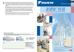
1 The system does not start
operation at all.
Supposed Cause Countermeasure
Blowout of
Turn OFF the power
fuse(s)
supply and then
replace the fuse(s).
Cutout of
• If the knob of any
breaker(s)
breaker is in its
OFF position,
turn ON the
power supply.
• If the knob of any
circuit breaker is
in its tripped
position, do not
turn ON the
power supply.
ON
Knob
Tripped
OFF
Circuit breaker
Power failure
Blocked air inlet or outlet
of indoor or outdoor unit
Clogged air
filter(s)
Blocked air inlet or outlet
3 The system does not cool or
of indoor or outdoor unit
heat air well.
Clogged air filter(s)
Enclosed outdoor unit(s)
Improper set
temperature
Airflow rate set to
"LOW"
Improper direction
of air diffusion
Open window(s) or door(s)
[In cooling] Direct sunlight
received
[In cooling] Too many persons
staying in a room
[In cooling] Too many heat sources
(e.g. OA equipment)
located in a room
2 The system starts operation but
makes an immediate stop.
After the power
failure is reset,
restart the system.
Remove
obstacle(s).
Clean the air
filter(s).
Remove
obstacle(s).
Clean the air filter(s).
Remove the enclosure.
Set the temperature to
a proper degree.
Set it to a proper
airflow rate.
Set it to a proper
direction.
Shut it tightly.
Hang curtains or
shades on windows.
The model must
be selected to
match the air
conditioning load.
12
: http://splitoff.ru/tehn-doc.html
Symptom-based Troubleshooting
Symptom
4 The system The system stops
does not
and immediately
operate.
restarts operation.
Pressing the
TEMP ADJUST
button immediately
resets the system.
Supposed Cause
If the OPERATION
lamp on the remote
controller turns ON,
the system will be
normal. These
symptoms indicate
that the system is
controlled so as not to
put unreasonable
loads on the system.
The remote
The system is
controller displays
controlled with
"UNDER
centralized
CENTRALIZED
controller. Blinking
CONTROL", which display indicates that
blinks for a period of the system cannot
several seconds
be operated using
when the
the remote
OPERATION button controller.
is depressed.
The system stops The system is in
immediately after
preparation mode
turning ON the
of micro computer
power supply.
operation.
5 The system The remote
The system stops
makes
controller
due to an
intermittent
displays error
interruption in
stops.
communication
codes "U4" and
between units
"U5", and the
caused by electrical
system stops but
noises coming from
restarts after a
equipment other
lapse of several
than air
minutes.
conditioners.
This remote
6 COOL-HEAT The remote
controller displays controller has no
selection is
"UNDER
option to select
disabled.
CENTRALIZED
cooling operation.
CONTROL".
COOL-HEAT
The remote
controller displays selection is made
using the COOL"UNDER
HEAT selection
CENTRALIZED
CONTROL", and remote controller.
the COOL-HEAT
selection remote
controller is
provided.
Countermeasure
Normal operation.
The system will
automatically
start operation
after a lapse of 5
minutes.
Operate the
system using the
COOL/HEAT
centralized
remote controller.
Wait for a period
of approximately
1 minute.
Remove causes
of electrical
noises.
If these causes
are removed, the
system will
automatically
restart operation.
Use a remote
controller with
option to select
cooling operation.
Use the COOLHEAT selection
remote controller
to select cool or
heat.
13
: http://splitoff.ru/tehn-doc.html
Symptom-based Troubleshooting
Symptom
7 The system
This symptom
conducts fan occurs
operation but immediately after
not cooling or turning ON the
power supply.
heating
operation.
8 The airflow
Even pressing the
rate is not
AIRFLOW RATE
reproduced SET button
according to makes no
the setting.
changes in the
airflow rate.
9 The airflow
direction is
not
reproduced
according to
the setting.
The airflow
direction is not
corresponding to
that displayed on
the remote
controller.
The flap does not
swing.
Supposed Cause
The system is in
preparation mode
of operation.
Countermeasure
Wait for a period
of approximately
10 minutes.
In heating operation, Normal operation.
when the room
temperature reaches
the set degree, the
outdoor unit will stop
while the indoor unit
is brought to fan LL
operation so that no
one gets cold air.
Furthermore, if fan
operation mode is
selected when other
indoor unit is in
heating operation,
the system will be
brought to fan LL
operation.
(The fan LL
operation is also
enabled while in oil
return mode in
cooling operation.)
Automatic control Normal operation.
14
: http://splitoff.ru/tehn-doc.html
Symptom-based Troubleshooting
Symptom
10 A white mist <Indoor unit>
comes out
In cooling
from the
operation, the
system.
ambient humidity
is high.
(This indoor unit
is installed in a
place with much
oil or dust.)
<Indoor unit>
Immediately after
cooling operation
stopping, the
ambient
temperature and
humidity are low.
<Indoor and
outdoor units>
After the
completion of
defrosting
operation, the
system is
switched to
heating
operation.
Supposed Cause Countermeasure
Uneven
Clean the inside
temperature
of the indoor unit.
distribution due to
heavy stain of the
inside of the
indoor unit
Hot gas
Normal operation.
(refrigerant) flown
in the indoor unit
results to be
vapor from the
unit.
Defrosted
moisture turns to
be vapor and
comes out from
the units.
Normal operation.
15
: http://splitoff.ru/tehn-doc.html
Symptom-based Troubleshooting
Symptom
11 The system <Indoor unit>
produces
Immediately after
sounds.
turning ON the
power supply, indoor
unit produces
"ringing" sounds.
<Indoor and
outdoor units>
"Hissing" sounds are
continuously
produced while in
cooling or defrosting
operation.
<Indoor and
outdoor units>
"Hissing" sounds are
produced
immediately after the
startup or stop of the
system, or the
startup or stop of
defrosting operation.
<Indoor unit>
Faint sounds are
continuously
produced while in
cooling operation
or after stopping
the operation.
<Indoor unit>
"Creaking" sounds
are produced
while in heating
operation or after
stopping the
operation.
<Indoor unit>
Sounds like
"trickling" or the
like are produced
from indoor units
in the stopped
state.
Supposed Cause
These are
operating sounds
of the electronic
expansion valve
of the indoor unit.
Countermeasure
Normal operation.
This sound
becomes low
after a lapse of
approximately 1
minute.
These sounds are Normal operation.
produced from gas
(refrigerant)
flowing
respectively
through the indoor
and outdoor units.
These sounds
Normal operation.
are produced
when the gas
(refrigerant) stops
or changes
flowing.
These sounds
are produced
from the drain
discharge device
in operation.
Normal operation.
These sounds
Normal operation.
are produced
from resin parts
expanding and
contracting with
temperature
changes.
On VRV systems, Normal operation.
these sounds are
produced when
other indoor units
in operation. The
reason is that the
system runs in
order to prevent
oil or refrigerant
from dwelling.
<Outdoor unit>
The reason is that Normal operation.
Pitch of operating the compressor
sounds changes. changes the
operating
frequency.
16
: http://splitoff.ru/tehn-doc.html
Symptom-based Troubleshooting
Symptom
12 Dust comes Dust comes out
out from the from the system
system.
when it restarts
after the stop for
an extended
period of time.
13 Odors come In operation
out from the
system.
Supposed Cause Countermeasure
Dust, which has Normal operation.
deposited on the
inside of indoor
unit, is blown out
from the system.
Odors of room,
cigarettes or else
adsorbed to the
inside of indoor
unit are blown out.
14 Outdoor unit In operation
The reason is that
fan does not
fan revolutions
rotate.
are controlled to
put the operation
to the optimum
state.
15 LCD display Immediately after The reason is that
the system is
"88" appears turning ON the
power supply
checking to be
on the
sure the remote
remote
controller is
controller.
normal.
16 The outdoor
unit
compressor
or the
outdoor unit
fan does not
stop.
17 The outdoor
gets hot.
After stopping
operation
While stopping
operation
18 Hot air
Hot air is felt
comes out
while the system
from the
stops.
system even
though it
stops.
19 The system The system is in
does not cool dry operation.
air well.
The inside of the
indoor unit should
be cleaned.
Normal operation.
Normal operation.
This code is
displayed for a
period of
approximately 1
minute at
maximum.
It stops in order to Normal operation.
prevent oil or
It stops after a
refrigerant from
lapse of
dwelling.
approximately 5
to 10 minutes.
The reason is that
the compressor is
warmed up to
provide smooth
startup of the
system.
On VRV systems,
small quantity of
refrigerant is fed to
indoor units in the
stopped state when
other indoor units
are in operation.
The reason is that
the dry operation
serves not to
reduce the room
temperature
where possible.
Normal operation.
Normal operation.
Change the
system to cooling
operation.
17
: http://splitoff.ru/tehn-doc.html
Troubleshooting by Remote Controller
2. Troubleshooting by Remote
Controller
2.1 The INSPECTION / TEST
Button
The following modes can be selected by using the
[Inspection/Test Operation] button on the remote control.
Service data can be obtained.
• Error code history
• Temperature data of various sections
Service settings can be made.
• Forced fan ON
• Airflow direction/Airflow rate setting
Indoor unit settings
can be made
• Filter sign time
Depress
• Airflow direction
Inspection/Test Operation
• Others
Field
setting
mode
button for more than 4
seconds.
Depress
Inspection/Test Operation
button for more than 4
seconds.
Press
Inspection/Test Operation
button once.
Service
mode
Press
Inspection/Test Operation
button once.
Normal
mode
Press
Inspection/Test Operation
button once.
Or after 30 minutes
After 10 seconds
Inspection
mode
Press
Inspection/Test Operation
button once.
Following codes can
be checked.
• Error codes
• Indoor model code
• Outdoor model code
Test
operation
mode
Thermostat is forcibly
turned ON.
18
: http://splitoff.ru/tehn-doc.html
Troubleshooting by Remote Controller
2.2
Self-diagnosis by Wired
Remote Controller
2.2.1 Wired Remote Controller —
BRC1D61
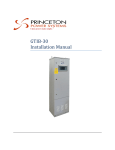
If operation stops due to error, the remote controller’s
operation LED blinks, and error code is displayed. (Even
if stop operation is carried out, error contents are
displayed when the inspection mode is entered.) The
error code enables you to tell what kind of error caused
operation to stop. Refer to P.24 for error code and error
contents.
Operation LED
ON/OFF
button
Display of indoor
unit for which an
error has been
detected
Inspection
display
Error code
Inspection/Test
button
Note:
1. Pressing the INSPECTION/TEST button will blink the
check indication.
2. While in service mode, holding down the ON/OFF
button for a period of 5 seconds or more will clear the
error history indication shown above. In this case, on
the codes display, the error code will blink twice and
then change to “00” (= Normal), the Unit No. will
change to “0”, and the operation mode will
automatically switch from service mode to normal
mode (displaying the set temperature).
19
: http://splitoff.ru/tehn-doc.html
Troubleshooting by Remote Controller
2.2.2 Wired Remote Controller —
BRC1E61
The following will be displayed on the screen when an
error (or a warning) occurs during operation.
Check the error code and take the corrective action
specified for the particular model.
Screen
Operation lamp
(1)Checking an error or warning
Operation
Status
Display
The operation lamp
(green) starts to blink.
The message "Error:
Abnormal The system
Press Menu button"
shutdown stops operating.
will appear and blink at
the bottom of the
screen.
Warning
The system
continues its
operation.
The operation lamp
(green) remains on.
The message
"Warning: Press Menu
button" will appear and
blink at the bottom of
the screen.
20
: http://splitoff.ru/tehn-doc.html
Troubleshooting by Remote Controller
(2)Taking corrective action
· Press the Menu/Enter button to check the error code.
· Take the corrective action specific to the model.
Error code
Applicable
model names
21
: http://splitoff.ru/tehn-doc.html
Troubleshooting by Remote Controller
2.3
Self-diagnosis by Wireless
Remote Controller
If unit stops due to an error, the operation indicating LED
on the signal receiving part of indoor unit flashes.
The error code can be determined by following the
procedure described below. (The error code is displayed
when an operation error has occurred. In normal
condition, the error code of the last problem is displayed.)
1
Press the INSPECTION/TEST button to select “inspection”. The
equipment enters the inspection mode. The “Unit” indication is
displayed and the Unit No. display shows flashing “0” indication.
2
Set the Unit No.
Press the UP or DOWN button and change the Unit No.
display until the buzzer (∗1) is generated from the indoor unit.
∗1 Number of beeps
3 short beeps : Conduct all of the following operations.
1 short beep : Conduct steps 3 and 4.
Continue the operation in step 4
until a buzzer remains ON. The
continuous buzzer indicates that
the error code is confirmed.
Continuous beep : No abnormality.
3
Press the MODE selector button.
The left “0” (upper digit) indication of the error code flashes.
4
Error code upper digit diagnosis
Press the UP or DOWN button and change the error code upper
digit until the error code matching buzzer (∗2) is generated.
The upper digit of the code changes as shown below
when the UP and DOWN buttons are pressed.
0 A CEH FJ LPU987 654
"UP" button
"DOWN" button
∗2 Number of beeps
Continuous beep : Both upper and lower digits
matched. (Error code confirmed)
2 short beeps : Upper digit matched.
1 short beep : Lower digit matched.
5
Press the MODE selector button.
The right “0” (lower digit) indication of the error code flashes.
6
Error code lower digit diagnosis
Press the UP or DOWN button and change the error code lower digit
until the continuous error code matching buzzer (∗2) is generated.
The lower digit of the code changes as shown below
when the UP and DOWN buttons are pressed.
0 1 234 567 89 AH CJ E F
"UP" button
"DOWN" button
22
: http://splitoff.ru/tehn-doc.html
Troubleshooting by Remote Controller
Normal status
Enters inspection mode from
normal status when the INSPECTION/
TEST button is pressed.
1 Press INSPECTION/TEST button.
If no button is pressed
for 1 minute, equipment
returns to normal status.
3
Press
MODE
selector
button.
When MODE selector
button is pressed or
no button is pressed
for 1 minute, equipment
returns to normal status.
If no button is pressed
for 1 minute, equipment
returns to normal status.
5 Press MODE selector button.
23
: http://splitoff.ru/tehn-doc.html
Error
FXM40- FXM200/
Reference
FXH FXA FXL FXN
Error Contents
FXC FXF FXK FXD FXYD FXS FXYB
Code
125L
250L
Page
A0 External Protection Device
h
h
h
h
h
h
h
h
h
h
h
h
h
46
Abnormality
A1 PCB Abnormality
h
h
h
h
h
h
h
h
h
h
h
h
h
48
A3 Drain Level Control
h
h
h
h
h
h
h
h
49
System (S1L) Abnormality
A6 Fan Motor (M1F) Lock,
h
h
h
52
Overload
A6 Indoor Unit Fan Motor
h
55
Abnormality
A6 Overload / Overcurrent /
Lock of Indoor Unit Fan
h
57
Motor
A6 Overload / Overcurrent /
Lock of Indoor Unit Fan
h
61
Motor
A7 Swing Flap Motor (M1S)
h
h
h
h
h
63
Abnormality
A9 Electronic Expansion
h
h
h
h
h
h
h
h
h
h
h
h
h
68
Valve Coil Abnormality
Troubleshooting by Remote Controller
2.4
Error Codes and Description
2.4.1 Indoor Unit
R-22
∗ For the model names, refer to P.2~11.
24
: http://splitoff.ru/tehn-doc.html
Error
FXM40- FXM200/
Reference
Error Contents
FXC FXF FXK FXD FXYD FXS FXYB
FXH FXA FXL FXN
Code
125L
250L
Page
AF Drain Level above Limit
h
h
h
h
h
h
71
AJ Capacity Determination
h
h
h
h
h
h
h
h
h
h
h
h
h
73
Device Abnormality
C4 Thermistor for Liquid Pipe
h
h
h
h
h
h
h
h
h
h
h
h
h
78
Abnormality
C5 Thermistor for Gas Pipe
h
h
h
h
h
h
h
h
h
h
h
h
h
80
Abnormality
C9 Thermistor for Suction Air
h
h
h
h
h
h
h
h
h
h
h
h
h
84
Abnormality
CA Thermistor for Discharge
h
h
h
h
h
h
h
h
h
h
h
h
h
86
Air Abnormality
CJ Room Temperature
Thermistor in Remote
h
h
h
h
h
h
h
h
h
h
h
h
h
90
Controller Abnormality
Troubleshooting by Remote Controller
∗ For the model names, refer to P.2~11.
: http://splitoff.ru/tehn-doc.html
25
h
h
h
h
A9
h
Electronic Expansion
Valve Coil Abnormality
h
h
Power Supply Voltage
Abnormality
A8
h
h
h
Swing Flap Motor (M1S)
Abnormality
h
h
A7
h
h
h
h
Overload / Overcurrent /
Lock of Indoor Unit Fan
Motor
h
h
h
A6
h
h
h
h
Overload / Overcurrent /
Lock of Indoor Unit Fan
Motor
h
h
h
h
A6
A3
h
h
Indoor Unit Fan Motor
Abnormality
Drain Level Control
System (S1L) Abnormality
h
A6
PCB Abnormality
A1
h
A6
External Protection Device
Abnormality
A0
h
h
h
h
h
h
h
h
h
h
h
h
h
h
h
h
h
h
h
h
h
h
h
h
h
FXCQ FXZQ FXFQ FXKQ FXDQ FXSQ FXMQ-P FXMQ-MA FXHQ FXAQ FXLQ FXNQ FXUQ
Fan Motor (M1F) Lock,
Overload
Error Contents
Error
Code
68
66
63
61
57
55
52
49
48
46
Reference
Page
Troubleshooting by Remote Controller
R-410A
∗ For the model names, refer to P.2~11.
26
: http://splitoff.ru/tehn-doc.html
Thermistor for Liquid Pipe
Abnormality
h
CJ
h
Room Temperature
Thermistor in Remote
Controller Abnormality
h
h
Humidity Sensor System
Abnormality
h
CC
h
h
h
h
h
h
h
h
h
h
h
h
h
h
h
h
h
h
h
h
h
C9
h
h
h
h
h
h
h
h
h
Thermistor for Discharge
CA
Air Abnormality
h
h
h
h
Thermistor for Suction Air
Abnormality
h
h
h
h
h
h
h
h
h
Combination Abnormality
C6 (between Indoor unit PCB
and Fan PCB)
Thermistor for Gas Pipe
C5
Abnormality
C4
h
h
Capacity Determination
Device Abnormality
Transmission Abnormality
C1 (between Indoor unit PCB
and Fan PCB)
h
Drain Level above Limit
h
h
h
h
h
h
h
h
h
h
h
h
h
h
h
h
h
h
h
h
h
h
h
h
h
h
h
h
h
h
h
h
h
h
h
h
h
h
h
FXCQ FXZQ FXFQ FXKQ FXDQ FXSQ FXMQ-P FXMQ-MA FXHQ FXAQ FXLQ FXNQ FXUQ
AJ
Error Contents
AF
Error
Code
90
88
86
84
82
80
78
75
73
71
Reference
Page
Troubleshooting by Remote Controller
∗ For the model names, refer to P.2~11.
: http://splitoff.ru/tehn-doc.html
27
28
: http://splitoff.ru/tehn-doc.html
Abnormal Discharge Pipe Temperature
F3 Abnormal Discharge Pipe Temperature
Electronic Expansion Valve Coil Abnormality
E9 Electronic Expansion Valve Coil Abnormality
Outdoor Unit Fan Motor Abnormality
Outdoor Unit Fan Motor Abnormality
Outdoor Unit Fan Motor Abnormality
E7 Outdoor Unit Fan Motor Abnormality
E6 STD Compressor Motor Overcurrent/Lock
Inverter Compressor Motor Lock
Inverter Compressor Motor Lock
h
h
h
h
E5 Inverter Compressor Motor Lock
Abnormal Suction Pressure
h
h
E4 Actuation of Low Pressure Sensor
Abnormal Discharge Pressure
E3 Actuation of High Pressure Sensor
h
M(A)
h
h
h
h
h
h
M
VRVII-S
R-22
Series VRVII
E2 Earth Leakage by Leak Detection PCB Assy
E1 PCB Abnormality
Error Contents
Refrigerant
h
h
h
h
h
h
h
M(A)
VRVII
R-410A
h
h
h
h
h
h
h
h
h
P(A)
h
h
h
h
h
h
h
M
h
h
h
h
h
h
h
P
h
h
h
h
h
h
M
h
h
h
h
h
h
h
P
h
h
h
h
h
h
h
h
h
P
VRVIII VRV-WII VRV-WIII VRVII-S VRVIII-S VRVIII-Q
139
136
133
130
127
125
121
117
115
112
109
107
104
102
99
97
94
92
Reference
Page
Troubleshooting by Remote Controller
2.4.2 Outdoor Unit
h
h
h
h
h
M
h
h
P
h
P
h
: http://splitoff.ru/tehn-doc.html
h
h
h
h
h
h
J7 Liquid Pipe Thermistor Abnormality
h
h
J6 Outdoor Unit Heat Exchanger Thermistor Abnormality
h
h
h
h
h
h
h
h
h
J5 Suction Pipe Thermistor Abnormality
h
J4 Heat Exchanger Gas Pipe Thermistor Abnormality
J3 Discharge Pipe Thermistor Abnormality
Current Sensor Abnormality
h
h
h
h
h
h
h
h
h
h
h
h
h
h
h
h
h
h
J2 Current Sensor Abnormality
h
h
h
h
h
h
h
h
P
J1 High Pressure Sensor Abnormality
HJ Water system Error
Outdoor Air Thermistor Abnormality
H9 Outdoor Air Thermistor Abnormality
Outdoor Unit Fan Motor Signal Abnormality
h
h
M
h
h
h
P(A)
H7 Outdoor Unit Fan Motor Signal Abnormality
h
h
M(A)
R-410A
VRVIII VRV-WII VRV-WIII VRVII-S VRVIII-S VRVIII-Q
h
h
h
M
VRVII
H3 High Pressure Switch System Abnormality
Refrigerant Overcharged
Refrigerant Overcharged
F6 Refrigerant Overcharged
h
M(A)
VRVII-S
R-22
Series VRVII
F3 Abnormal Discharge Pipe Temperature
Error Contents
Refrigerant
176
174
172
170
168
167
165
162
159
157
155
153
150
148
147
145
143
141
Reference
Page
Troubleshooting by Remote Controller
29
Momentary Overcurrent of Inverter Compressor
L8 Momentary Overcurrent of Inverter Compressor
Momentary Overcurrent of Inverter Compressor
L5 Momentary Overcurrent of Inverter Compressor
Inverter Radiation Fin Temperature
Rise Abnormality
L4 Inverter Radiation Fin Temperature
Rise Abnormality
Inverter PCB Abnormality
Inverter PCB Abnormality
L1 Inverter PCB Abnormality
Suction Pipe Pressure Sensor Abnormality
JC Low Pressure Sensor Abnormality
Discharge Pipe Pressure Sensor Abnormality
JA High Pressure Sensor Abnormality
h
h
h
h
h
h
h
h
h
h
h
h
h
h
h
h
h
h
h
h
h
h
h
h
P(A)
h
h
h
h
h
h
M
h
h
h
h
h
h
P
h
h
h
h
h
h
M
h
h
h
h
h
h
P
P
h
h
h
h
h
h
h
M(A)
R-410A
VRVIII VRV-WII VRV-WIII VRVII-S VRVIII-S VRVIII-Q
J9 Subcooling Heat Exchanger Gas Pipe Thermistor Abnormality
M
VRVII
h
M(A)
VRVII-S
R-22
Series VRVII
J8 Thermistor System Abnormality
Error Contents
Refrigerant
216
213
210
207
205
202
200
197
194
191
188
185
182
180
178
Reference
Page
Troubleshooting by Remote Controller
30
: http://splitoff.ru/tehn-doc.html
Field Setting Abnormality after
Replacing Main PCB or
Combination of PCB Abnormality
PJ Field Setting Abnormality after
Replacing Main PCB or
Combination of PCB Abnormality
Inverter Radiation Fin Thermistor Abnormality
P4 Inverter Radiation Fin Thermistor Abnormality
Inverter Over-Ripple Protection
P1 Inverter Over-Ripple Protection
Transmission Error between
Inverter and Control PCB
Transmission Error between
Inverter and Control PCB
LC Transmission Error between
Inverter and Control PCB
Inverter Compressor Startup Failure
h
h
h
h
M(A)
h
h
h
M
VRVII-S
R-22
Series VRVII
L9 Inverter Compressor Startup Failure
Error Contents
Refrigerant
h
h
h
h
M(A)
VRVII
R-410A
h
h
h
h
h
P(A)
h
h
h
h
M
h
h
h
h
P
h
h
h
M
h
h
h
h
P
h
h
h
h
h
P
VRVIII VRV-WII VRV-WIII VRVII-S VRVIII-S VRVIII-Q
245
243
241
239
237
234
231
229
226
223
219
Reference
Page
Troubleshooting by Remote Controller
: http://splitoff.ru/tehn-doc.html
31
32
: http://splitoff.ru/tehn-doc.html
Power Supply Insufficient or
Instantaneous Error
Power Supply Insufficient or
Instantaneous Error
Power Supply Insufficient or
Instantaneous Error
Power Supply Insufficient or
Instantaneous Error
h
h
U1 Reverse Phase, Open Phase
U2 Power Supply Insufficient or
Instantaneous Error
h
Refrigerant Shortage Alert
Refrigerant Shortage Alert
U0 Refrigerant Shortage Alert
Field Setting Abnormality after
Replacing Main PCB or
Combination of PCB Abnormality
h
M(A)
h
h
M
VRVII-S
R-22
Series VRVII
PJ Field Setting Abnormality after
Replacing Main PCB or
Combination of PCB Abnormality
Error Contents
Refrigerant
h
h
h
h
M(A)
VRVII
R-410A
h
h
h
P(A)
h
h
h
M
h
h
h
P
h
h
M
h
h
P
h
h
h
P
VRVIII VRV-WII VRV-WIII VRVII-S VRVIII-S VRVIII-Q
277
272
269
266
261
259
256
253
250
249
247
Reference
Page
Troubleshooting by Remote Controller
Transmission Error between Indoor
and Outdoor Units in the Same
System
U9 Transmission Error between Indoor and
Outdoor Units in the Same System
U8 Transmission Error between Main
and Sub Remote Controllers
Transmission Error (Across Outdoor Units)
h
h
h
h
U5 Transmission Error between
Remote Controller and Indoor Unit
U7 Transmission Error (Across Outdoor Units)
h
Transmission Error between Indoor
Units and Outdoor Units
Transmission Error between Indoor
Units and Outdoor Units
U4 Transmission Error between Indoor
Units and Outdoor Units
h
h
h
h
h
h
h
M
U3 Check Operation is not Executed
M(A)
VRVII-S
R-22
Series VRVII
U2 Power Supply Insufficient or
Instantaneous Error
Error Contents
Refrigerant
h
h
h
h
h
h
M(A)
VRVII
R-410A
h
h
h
h
h
h
P(A)
h
h
h
h
h
h
M
h
h
h
h
h
h
P
h
h
h
h
h
h
M
h
h
h
h
h
P
h
h
h
h
h
h
P
VRVIII VRV-WII VRV-WIII VRVII-S VRVIII-S VRVIII-Q
318
316
314
311
300
298
294
289
285
283
280
Reference
Page
Troubleshooting by Remote Controller
: http://splitoff.ru/tehn-doc.html
33
h
h
h
UE Transmission Error between
Centralized Controller and Indoor Unit
UF System is not Set yet
h
UC Address Duplication of Centralized
Controller
UH System Abnormality, Refrigerant
System Address Undefined
h
Improper Combination of Indoor and Outdoor
Units, Indoor Units and Remote Controller
Improper Combination of Indoor and Outdoor
Units, Indoor Units and Remote Controller
M(A)
h
h
h
h
h
M
VRVII-S
R-22
Series VRVII
UA Improper Combination of Indoor and Outdoor
Units, Indoor Units and Remote Controller
Error Contents
Refrigerant
h
h
h
h
h
M(A)
VRVII
R-410A
h
h
h
h
h
P(A)
h
h
h
h
h
M
h
h
h
h
h
P
h
h
h
h
h
M
h
h
h
h
h
P
h
h
h
h
h
P
VRVIII VRV-WII VRV-WIII VRVII-S VRVIII-S VRVIII-Q
343
341
336
335
332
325
321
Reference
Page
Troubleshooting by Remote Controller
34
: http://splitoff.ru/tehn-doc.html
Troubleshooting by Remote Controller
2.5
Error Codes - Sub Codes
If an error code like the one shown below is displayed
when the navigation remote controller (BRC1E61 or 71)
is in use, make a detailed diagnosis or a diagnosis of the
relevant unit referring to the attached list of detailed error
codes.
2.5.1 Indoor Unit
Error
code
Troubleshooting
Description of error
Description of diagnosis
A6 - 01
Fan motor locked
A locked fan motor current has
been detected.
Turn the fan by hand to check for
the connection of connectors.
A6 - 10
Fan overcurrent error
A fan motor overcurrent has
been detected.
Check for the connection of the
connector between the fan motor
and the PCB for the fan. If the
connection is normal, replace the
fan motor. If this still cannot solve
the error, replace the PCB for the
fan.
A6 - 11
Fan position detection error
An error in the detection of
position of the fan motor. Check
for the connection of the
connector between the fan motor
and the PCB for the fan. If the
connection is normal, replace the
fan motor. If this still cannot solve
the error, replace the PCB for the
fan.
A8 - 01
Power supply voltage error
Check for the input voltage of the
fan motor.
A9 - 01
Electronic expansion valve
error
There is an error in the
expansion valve coil or a
connector disconnected.
A9 - 02
Refrigerant leakage
detection error
Refrigerant leaks even if the
electronic expansion valve is
closed.
Replace the electronic expansion
valve.
35
: http://splitoff.ru/tehn-doc.html
Troubleshooting by Remote Controller
Error
code
Troubleshooting
Description of error
AH - 03 Transmission error (between
the self-cleaning decoration
panel and the indoor unit)
[when the self-cleaning
decoration panel is mounted]
Description of diagnosis
Check for the connection of the
harness connector between the
panel PCB and the indoor unit
PCB.
AH - 04 Dust detection sensor error
Check for the connections of the
[when the self-cleaning
connector X12A on the panel
decoration panel is mounted] PCB and the connectors X18A
and X19A on the sensor PCB.
AH - 05 Dust collection sign error
Check for clogging with dust at
[when the self-cleaning
the dust collection port as well as
decoration panel is mounted] in the brush unit, S-shaped pipe,
and dust box. Furthermore,
check for any stains of the light
receiving and emitting parts of
the infrared unit.
AH - 06 Air filter rotation error
Check for anything getting in the
way of rotating the filter (e.g. the
[when the self-cleaning
decoration panel is mounted] filter comes off or the drive gear
is clogged with foreign matters).
AH - 07 Damper rotation error
The damper does not rotate
[when the self-cleaning
normally. Check for any foreign
decoration panel is mounted] matters around the damper and
for the operation of the gear and
limit switch.
AH - 08 Filter self-cleaning operation
error
[when the self-cleaning
decoration panel is mounted]
The unit has not yet completed
the filter self-cleaning operation
even after the lapse of specified
period of time. Check for any
external noise, etc.
AH - 09 Filter self-cleaning operation
start disabled error
[when the self-cleaning
decoration panel is mounted]
The unit has been put into a state
in which the filter self-cleaning
operation is disabled. Check the
unit for the operating conditions.
AJ - 01
Capacity setting error
There is an error in the capacity
setting of the indoor unit PCB.
AJ - 02
Electronic expansion valve
setting error
There is a fault in the setting of
the gear type electronic
expansion valve/direct acting
type electronic expansion valve.
C1 - 01
Transmission error (between
indoor unit PCB and the PCB
for the fan)
Check for the conditions of
transmission between the indoor
unit PCB and the PCB for the
fan.
36
: http://splitoff.ru/tehn-doc.html
Troubleshooting by Remote Controller
Error
code
Troubleshooting
Description of error
Description of diagnosis
C6 - 01
Faulty combination of indoor
unit PCB and the PCB for the
fan
A combination of indoor unit PCB
and the PCB for the fan is faulty.
Check whether the capacity
setting adaptor is correct and the
type of the PCB for the fan is
correct.
U4 - 01
Indoor-Outdoor transmission
error
Refer to the “U4” flow chart.
UA - 13 Refrigerant type error
The type of refrigerant used for
the indoor unit is different from
that used for the outdoor unit.
UA - 15 Not applicable for selfAn outdoor unit is not applicable
cleaning decoration panel
for the self-cleaning decoration
[when the self-cleaning
panel is connected.
decoration panel is mounted]
37
: http://splitoff.ru/tehn-doc.html
Troubleshooting by Remote Controller
2.5.2 Outdoor Unit
Error
code
Troubleshooting
Description of error
E3 - 01
E3 - 02
High pressure switch
activated (Master)
E3 - 03
E3 - 04
High pressure switch
activated (Slave 1)
E3 - 05
E3 - 06
High pressure switch
activated (Slave 2)
E3 - 07
High pressure switch
activated (Batch)
E4 - 01
Low pressure error (Master)
E4 - 02
Low pressure error (Slave 1)
E4 - 03
Low pressure error (Slave 2)
E5 - 01
INV. compressor lock
(Master)
E5 - 02
E5 - 03
Description of diagnosis
Refer to the “E3” flow chart of
each manual and make a
diagnosis of the relevant unit
based on the Error code shown
to the left.
Refer to the “E4” flow chart of
each manual and make a
diagnosis of the relevant unit
based on the Error code shown
to the left.
Refer to the “E5” flow chart of
each manual and make a
INV. compressor lock (Slave 1) diagnosis of the relevant unit
based on the Error code shown
INV. compressor lock (Slave 2) to the left.
E6 - 01
STD compressor 1 OC
activated (Master)
E6 - 02
STD compressor 2 OC
activated (Master)
E6 - 03
STD compressor 1 OC
activated (Slave 1)
E6 - 04
STD compressor 2 OC
activated (Slave 1)
E6 - 05
STD compressor 1 OC
activated (Slave 2)
E6 - 06
STD compressor 2 OC
activated (Slave 2)
Refer to the “E6” flow chart of
each manual and make a
diagnosis of the relevant
compressor of the relevant unit
based on the Error code shown
to the left.
38
: http://splitoff.ru/tehn-doc.html
Troubleshooting by Remote Controller
Error
code
E7 - 01
Troubleshooting
Description of error
Description of diagnosis
Fan motor 1 lock (Master)
E7 - 02
Fan motor 2 lock (Master)
E7 - 05
Fan motor 1 instantaneous
overcurrent (Master)
E7 - 06
Fan motor 2 instantaneous
overcurrent (Master)
E7 - 09
Fan motor 1 IPM error
(Master)
E7 - 10
Fan motor 2 IPM error
(Master)
E7 - 13
Fan motor 1 lock (Slave 1)
E7 - 14
Fan motor 2 lock (Slave 1)
E7 - 17
Fan motor 1 instantaneous
overcurrent (Slave 1)
E7 - 18
Fan motor 2 instantaneous
overcurrent (Slave 1)
E7 - 21
Fan motor 1 IPM error (Slave 1)
E7 - 22
Fan motor 2 IPM error (Slave 1)
E7 - 25
Fan motor 1 lock (Slave 2)
E7 - 26
Fan motor 2 lock (Slave 2)
E7 - 29
Fan motor 1 instantaneous
overcurrent (Slave 2)
E7 - 30
Fan motor 2 instantaneous
overcurrent (Slave 2)
E7 - 33
Fan motor 1 IPM error (Slave 2)
E7 - 34
Fan motor 2 IPM error (Slave 2)
E9 - 01
Electronic expansion valve 1 coil error (Master)
E9 - 04
Electronic expansion valve 2 coil error (Master)
E9 - 05
Electronic expansion valve 1 coil error (Slave 1)
E9 - 07
Electronic expansion valve 2 coil error (Slave 1)
E9 - 08
Electronic expansion valve 1 coil error (Slave 2)
E9 - 10
Electronic expansion valve 2 coil error (Slave 2)
F3 - 01
Discharge pipe temperature
error (Master)
F3 - 03
Discharge pipe temperature
error (Slave 1)
F3 - 05
Discharge pipe temperature
error (Slave 2)
Refer to the following to make a
diagnosis of the fan motor of the
relevant unit.
{ For fan motor lock, refer to
E7-01, -02, -13, -14, -25,
and -26.
{ For instantaneous
overcurrent, refer to E7-05,
-06, -17, -18, -29, and -30.
{ For IPM error, refer to E7-09,
-10, -21, -22, -33, and -34.
Refer to the “E9” flow chart of
each manual and make a
diagnosis of the relevant
electronic expansion valve of the
relevant unit based on the Error
code shown to the left.
Refer to the “F3” flow chart of
each manual and make a
diagnosis of the relevant unit
based on the Error code shown
to the left.
39
: http://splitoff.ru/tehn-doc.html
Troubleshooting by Remote Controller
Error
code
Troubleshooting
Description of error
Description of diagnosis
F6 - 02
Excess refrigerant charge
error
Excess refrigerant charge was
detected during test run.
F6 - 03
Excess refrigerant charge
warning
Excess refrigerant charge was
detected during operation other
than test run.
H7 - 01
Fan motor 1 signal error
(Master)
H7 - 02
Fan motor 2 signal error
(Master)
H7 - 05
Fan motor 1 signal error
(Slave 1)
Refer to the “H7” flow chart of
each manual and make a
diagnosis of the relevant unit
based on the Error code shown
to the left.
H7 - 06
Fan motor 2 signal error
(Slave 1)
H7 - 09
Fan motor 1 signal error
(Slave 2)
H7 - 10
Fan motor 2 signal error
(Slave 2)
H9 - 01
Faulty outdoor air thermistor
(Master)
H9 - 02
Faulty outdoor air thermistor
(Slave 1)
H9 - 03
Faulty outdoor air thermistor
(Slave 2)
J2 - 01
Faulty current sensor
(Master: STD compressor 1)
J2 - 02
Faulty current sensor
(Master: STD compressor 2)
J2 - 03
Faulty current sensor (Slave
1: STD compressor 1)
J2 - 04
Faulty current sensor (Slave
1: STD compressor 2)
J2 - 05
Faulty current sensor (Slave
2: STD compressor 1)
J2 - 06
Faulty current sensor (Slave
2: STD compressor 2)
J2 - 07
Current sensor error
(System)
Refer to the “H9” flow chart of
each manual and make a
diagnosis of the relevant unit
based on the Error code shown
to the left.
Refer to the “J2” flow chart of
each manual and make a
diagnosis of the relevant
compressor of the relevant unit
based on the Error code shown
to the left.
40
: http://splitoff.ru/tehn-doc.html
Troubleshooting by Remote Controller
Error
code
Troubleshooting
Description of error
J3 - 01
Faulty discharge pipe
thermistor 1 (Master: INV.
compressor)
J3 - 02
Faulty discharge pipe
thermistor 2 (Master: STD
compressor 1)
J3 - 03
Faulty discharge pipe
thermistor 3 (Master: STD
compressor 2)
J3 - 04
Faulty discharge pipe
thermistor 1 (Slave 1: INV.
compressor)
J3 - 05
Faulty discharge pipe
thermistor 2 (Slave 1: STD
compressor 1)
J3 - 06
Faulty discharge pipe
thermistor 3 (Slave 1: STD
compressor 2)
J3 - 07
Faulty discharge pipe
thermistor 1 (Slave 2: INV.
compressor)
J3 - 08
Faulty discharge pipe
thermistor 2 (Slave 2: STD
compressor 1)
J3 - 09
Faulty discharge pipe
thermistor 3 (Slave 2: STD
compressor 2)
J5 - 01
Faulty suction pipe
thermistor (Master)
J5 - 02
Faulty accumulator inlet
thermistor (Master)
J5 - 03
Faulty suction pipe
thermistor (Slave 1)
J5 - 04
Faulty accumulator inlet
thermistor (Slave 1)
J5 - 05
Faulty suction pipe
thermistor (Slave 2)
J5 - 06
Faulty accumulator inlet
thermistor (Slave 2)
Description of diagnosis
Refer to the “J3” flow chart of
each manual and make a
diagnosis of the relevant
compressor of the relevant unit
based on the Error code shown
to the left.
Refer to the “J5” flow chart of
each manual and make a
diagnosis of the relevant
thermistor of the relevant unit
based on the Error code shown
to the left.
41
: http://splitoff.ru/tehn-doc.html
Troubleshooting by Remote Controller
Error
code
Troubleshooting
Description of error
J6 - 01
Faulty heat exchanger
thermistor (Master)
J6 - 02
Faulty heat exchanger
thermistor (Slave 1)
J6 - 03
Faulty heat exchanger
thermistor (Slave 2)
J7 - 01
Faulty liquid pipe thermistor
(Master)
J7 - 02
Faulty liquid pipe thermistor
(Slave 1)
J7 - 03
Faulty liquid pipe thermistor
(Slave 2)
J9 - 01
Faulty subcooling heat
exchanger outlet thermistor
(Master)
J9 - 02
Faulty subcooling heat
exchanger outlet thermistor
(Slave 1)
J9 - 03
Faulty subcooling heat
exchanger outlet thermistor
(Slave 2)
JA - 01
Faulty high pressure sensor
(Master)
JA - 02
Faulty high pressure sensor
(Slave 1)
JA - 03
Faulty high pressure sensor
(Slave 2)
JC - 01
Faulty low pressure sensor
(Master)
JC - 02
Faulty low pressure sensor
(Slave 1)
JC - 03
Faulty low pressure sensor
(Slave 2)
L1 - 01
Instantaneous overcurrent
(Master: Inverter PCB)
L1 - 02
Current sensor error (Master:
Inverter PCB)
L1 - 03
Current offset error (Master:
Inverter PCB)
Description of diagnosis
Refer to the “J6” flow chart of
each manual and make a
diagnosis of the relevant
thermistor based on the Error
code shown to the left.
Refer to the “J7” flow chart of
each manual and make a
diagnosis of the relevant
thermistor based on the Error
code shown to the left.
Refer to the “J9” flow chart of
each manual and make a
diagnosis of the relevant
thermistor based on the Error
code shown to the left.
Refer to the “JA” flow chart of
each manual and make a
diagnosis of the relevant sensor
based on the Error code shown
to the left.
Refer to the “JC” flow chart of
each manual and make a
diagnosis of the relevant sensor
based on the Error code shown
to the left.
The inverter PCB may be faulty.
Refer to the “L1” flow chart of
each manual and make a
diagnosis of the relevant unit
based on the Error code shown
to the left.
42
: http://splitoff.ru/tehn-doc.html
Troubleshooting by Remote Controller
Error
code
Troubleshooting
Description of error
Description of diagnosis
L1 - 04
IGBT error (Master: Inverter
PCB)
The inverter PCB may be faulty
or a PCB other than the specified
one is mounted. Refer to the “L1”
flow chart of each manual and
make a diagnosis of the relevant
unit based on the Error code
shown to the left.
L1 - 07
Instantaneous overcurrent
(Slave 1: Inverter PCB)
L1 - 08
Current sensor error (Slave
1: Inverter PCB)
L1 - 09
Current offset error (Slave 1:
Inverter PCB)
The inverter PCB may be faulty.
Refer to the “L1” flow chart of
each manual and make a
diagnosis of the relevant unit
based on the Error code shown
to the left.
L1 - 10
IGBT error (Slave 1: Inverter
PCB)
The inverter PCB may be faulty
or a PCB other than the specified
one is mounted.
Refer to the “L1” flow chart of
each manual and make a
diagnosis of the relevant unit
based on the Error code shown
to the left.
L1 - 12
Instantaneous overcurrent
(Slave 2: Inverter PCB)
L1 - 13
Current sensor error (Slave
2: Inverter PCB)
L1 - 14
Current offset error (Slave 2:
Inverter PCB)
The inverter PCB may be faulty.
Refer to the “L1” flow chart of
each manual and make a
diagnosis of the relevant unit
based on the Error code shown
to the left.
L1 - 15
IGBT error (Slave 2: Inverter
PCB)
The inverter PCB may be faulty
or a PCB other than the specified
one is mounted.
Refer to the “L1” flow chart of
each manual and make a
diagnosis of the relevant unit
based on the Error code shown
to the left.
L4 - 01
Radiation fin temperature
rise (Master: Inverter PCB)
L4 - 02
Radiation fin temperature
rise (Slave 1: Inverter PCB)
L4 - 03
Radiation fin temperature
rise (Slave 2: Inverter PCB)
Refer to the “L4” flow chart of
each manual and make a
diagnosis of the relevant unit
based on the Error code shown
to the left.
L5 - 03
Current offset error (Master)
L5 - 05
Current offset error (Slave 1)
L5 - 07
Current offset error (Slave 2)
Refer to the “L5” flow chart of each
manual and make a diagnosis of
the relevant unit based on the
Error code shown to the left.
43
: http://splitoff.ru/tehn-doc.html
Troubleshooting by Remote Controller
Error
code
Troubleshooting
Description of error
L8 - 03
INV. compressor
instantaneous overcurrent
error (Master)
L8 - 06
INV. compressor
instantaneous overcurrent
error (Slave 1)
L8 - 07
INV. compressor
instantaneous overcurrent
error (Slave 2)
L9 - 01
INV. compressor startup
failure (Master)
L9 - 05
INV. compressor startup
failure (Slave 1)
L9 - 06
INV. compressor startup
failure (Slave 2)
LC - 01
Transmission error [between
INV. PCB and main PCB]
(Master)
LC - 06
Transmission error [between
INV. PCB and main PCB]
(Slave 1)
LC - 08
Transmission error [between
INV. PCB and main PCB]
(Slave 2)
P1 - 01
Unbalanced power supply
voltage (Master)
P1 - 02
Unbalanced power supply
voltage (Slave 1)
P1 - 03
Unbalanced power supply
voltage (Slave 2)
PJ - 04
Faulty combination of INV.
PCB (Master)
PJ - 05
Faulty combination of INV.
PCB (Slave 1)
PJ - 06
Faulty combination of INV.
PCB (Slave 2)
U0 - 03
Gas shortage alarm
Description of diagnosis
Refer to the “L8” flow chart of
each manual and make a
diagnosis of the relevant
compressor of the relevant unit
based on the Error code shown
to the left.
Refer to the “L9” flow chart of
each manual and make a
diagnosis of the relevant
compressor of the relevant unit
based on the Error code shown
to the left.
Refer to the “LC1” flow chart of
each manual and make a
diagnosis of the relevant unit
based on the Error code shown
to the left.
Refer to the “P1” flow chart of
each manual and make a
diagnosis of the relevant unit
based on the Error code shown
to the left.
Refer to the “PJ” flow chart of
each manual and make a
diagnosis of the relevant unit
based on the Error code shown
to the left.
Refer to the “U0” flow chart.
44
: http://splitoff.ru/tehn-doc.html
Troubleshooting by Remote Controller
Error
code
Troubleshooting
Description of error
U1 - 01
Reverse phase/open phase
for power supply (Master)
U1 - 04
Reverse phase for power
supply [with power supply
turned ON] (Master)
U1 - 05
Reverse phase/open phase
for power supply (Slave 1)
U1 - 06
Reverse phase for power
supply [with power supply
turned ON] (Slave 1)
U1 - 07
Reverse phase/open phase
for power supply (Slave 2)
U1 - 08
Reverse phase for power
supply [with power supply
turned ON] (Slave 2)
Description of diagnosis
Refer to the “U1” flow chart of
each manual and make a
diagnosis of the relevant unit
based on the Error code shown
to the left.
45
: http://splitoff.ru/tehn-doc.html
Troubleshooting by Indication on the Remote Controller
3. Troubleshooting by
Indication on the Remote
Controller
3.1
A0 External Protection Device
Abnormality
Remote Controller Display
A0
Applicable Models
All indoor models
Method of Error Detection
Detect open or short circuit between external input
terminals in indoor unit.
Error Decision Conditions
When an open circuit occurs between external input
terminals with the remote controller set to "external ON/
OFF terminal".
Supposed Causes
Actuation of external protection device
Improper field setting
Defective indoor unit PCB
46
: http://splitoff.ru/tehn-doc.html
Troubleshooting by Indication on the Remote Controller
Troubleshooting
Caution
Be sure to turn off the power switch before
connecting or disconnecting connectors, or parts
may be damaged.
External
protection
device is connected
to terminals T1 and
T2 of the indoor
unit terminal
block.
YES
Actuation of
external
protection
device.
NO
Check the setting state of
the external ON/OFF
input by remote
controller.
ON/OFF
input from
outside (mode
No. 12, first code
No. 1) has been set
to external protection
device input (second
code No. 03) by
remote
controller.
NO
YES
Change the
second code No.
to "01" or "02".
Replace the
indoor unit PCB.
47
: http://splitoff.ru/tehn-doc.html
Troubleshooting by Indication on the Remote Controller
A1 PCB Abnormality
3.2
Remote Controller Display
A1
Applicable Models
All indoor models
Method of Error Detection
Check data from E²PROM.
Error Decision Conditions
When data could not be correctly received from the
E²PROM
E²PROM : Type of nonvolatile memory. Maintains
memory contents even when the power supply
is turned OFF.
Supposed Causes
Defective indoor unit PCB
External factor (Noise etc.)
Troubleshooting
Caution
Be sure to turn off the power switch before
connecting or disconnecting connectors, or parts
may be damaged.
Turn the power supply
OFF, then the power ON
again.
Does the
system return to
normal?
NO
YES
The indoor unit
PCB is normal.
External factor
other than error
(for example,
noise etc.).
Replace the
indoor unit PCB.
48
: http://splitoff.ru/tehn-doc.html
Troubleshooting by Indication on the Remote Controller
A3 Drain Level Control System
3.3
(S1L) Abnormality
Remote Controller Display
A3
Applicable Models
R-22: FXC, FXF, FXA, FXK, FXH (Option), FXM
(Option), FXYB
R-410A: FXFQ, FXZQ, FXDQ, FXMQ-P, FXHQ (Option),
FXAQ (Option)
Method of Error Detection
By float switch OFF detection
Error Decision Conditions
When rise of water level is not a condition and the float
switch goes OFF
Supposed Causes
Proper power supply is not provided
Defective float switch or short circuit connector
Defective drain pump
Drain clogging, upward slope, etc.
Defective indoor unit PCB
Loose connection of connector
49
: http://splitoff.ru/tehn-doc.html
Troubleshooting by Indication on the Remote Controller
Troubleshooting
Caution
Be sure to turn off the power switch before
connecting or disconnecting connectors, or parts
may be damaged.
Is power
supply 220~240V
provided?
NO
Provide
220~240V power
supply.
YES
The
float switch
is connected to
connector of the
indoor unit
PCB.
NO
YES
The
float
switch contact
is forming a short
circuit (continuity check
with connector
disconnected)
NO
A
short circuit
connector is
connected to
PCB.
YES
NO
YES
Becomes
normal when
connector of the indoor
unit PCB is short
circuited
NO
YES
Water builds
up in the drain
pan.
YES
Connect either a
short circuit
connector or float
switch and turn
ON again.
Defective indoor
unit PCB.
Loose the
connection of
connector.
NO
The float
switch functions
normally.
NO
Replace the float
switch.
YES
The
drain
pump is
connected to
connector terminals
of the indoor
unit PCB.
Modify the float
switch's
connection and
turn ON again.
NO
Connect the
drain pump and
turn ON again.
YES
A
50
: http://splitoff.ru/tehn-doc.html
Troubleshooting by Indication on the Remote Controller
A
The
drain pump
works when the
power supply is reset
for the indoor unit.
YES
Check the drain
piping for
clogging or
upward slope,
etc.
NO
The
voltage
of terminals
Y1 and Y2 or
connector is
220~240 V (within 5
minutes of resetting
the power
supply).
NO
Replace the
indoor unit PCB.
YES
Replace the
drain pump or
check for dirt,
etc.
51
: http://splitoff.ru/tehn-doc.html
Troubleshooting by Indication on the Remote Controller
3.4
A6 Fan Motor (M1F) Lock,
Overload
Remote Controller Display
A6
Applicable Models
R-22: FXA, FXF, FXH
R-410A: FXAQ, FXFQ, FXHQ
Method of Error Detection
Abnormal fan revolutions are detected by a signal output
from the fan motor.
Error Decision Conditions
When the fan revolutions do not increase
Supposed Causes
Broken wires, short circuits, and loose connections in
the fan motor harness
Defective fan motor
(Broken wires or defective insulation)
Abnormal signal output from the fan motor (defective
circuit)
Defective PCB
Instantaneous disturbance in the power supply voltage
Fan motor lock
(Due to motor or external causes)
The fan does not rotate due to foreign matters
blocking the fan.
Disconnection of the connector between the highpower PCB and the low-power PCB.
52
: http://splitoff.ru/tehn-doc.html
Troubleshooting by Indication on the Remote Controller
Troubleshooting
Caution
Be sure to turn off the power switch before
connecting or disconnecting connectors, or parts
may be damaged.
Turn OFF the power
supply, and then wait for a
period of 10 minutes.
Are there
any foreign matters
around the fan?
YES
Remove the
foreign matters.
NO
Is the
connector for
the fan motor
properly connected to
the indoor unit
PCB? (∗1)
NO
Properly connect
the connector.
YES
By
disconnecting
the connector for
the fan motor from the
indoor unit PCB, the
fan can be lightly
rotated by
hand.
NO
Replace the fan
motor.
YES
Disconnect the connector
from the fan motor, and
then make measurement
of resistance between
pins. (∗2)
Is the
resistance
between the pins
more than the
judgement
criteria?
YES
NO
Replace the fan
motor.
Replace the
indoor unit PCB.
53
: http://splitoff.ru/tehn-doc.html
Troubleshooting by Indication on the Remote Controller
Note:
∗1. If any junction connector is provided between the
connector on the indoor unit PCB and the fan motor,
also check whether or not the junction connector is
properly connected.
∗2. All resistance measuring points and judgement
criteria.
(Example)
FXA(Q)
1 White
FG
2 Orange
Vsp
3 Brown
Vcc
4 Blue
GND
5
—
6
—
7 Red
Vdc
FXF(Q)
1 2 3 4 5
— — FG Vsp Vcc
{ { { { {
{
Vdc
1
{
GND
2
{
—
3
Judgement Criteria
Measuring point
FG-GND
Vsp-GND
Vcc-GND
Vdc-GND
Criteria
1MΩ or more
100kΩ or more
100Ω or more
100kΩ or more
54
: http://splitoff.ru/tehn-doc.html
Troubleshooting by Indication on the Remote Controller
3.5
A6 Indoor Unit Fan Motor
Abnormality
Remote Controller Display
A6
Applicable Models
FXD(Q)
Method of Error Detection
This error is detected if there is no revolutions detection
signal output from the fan motor.
Error Decision Conditions
When no revolutions can be detected even at the
maximum output voltage to the fan
Supposed Causes
Defective indoor fan motor
Broken wires
Defective contact
55
: http://splitoff.ru/tehn-doc.html
Troubleshooting by Indication on the Remote Controller
Troubleshooting
Be sure to turn off the power switch before
connecting or disconnecting connectors, or parts
may be damaged.
Caution
Is the connector
securely
connected?
NO
YES
Is
the
power of
approx. 12VDC
supplied between
the Pins1 and 3 when
the connector is
disconnected and
the power
supply turns
ON?
YES
Properly connect
the connectors.
(At this time,
check for any
defective
connector
contact or broken
wires.)
Check the indoor
unit fan motor
and the wiring
circuits of the fan
motor.
NO
Replace the
indoor unit PCB.
56
: http://splitoff.ru/tehn-doc.html
Troubleshooting by Indication on the Remote Controller
3.6
A6 Overload/Overcurrent/Lock
of Indoor Unit Fan Motor
Remote Controller Display
A6
Applicable Models
R-22: FXM40~125L
R-410A: FXMQ50~140P
Method of Error Detection
Detection from the current flow on the fan PCB.
Detection from the RPM of the fan motor in operation.
Detection from the position signal of the fan motor.
Detection from the current flow on the fan PCB when the
fan motor starting operation.
Error Decision Conditions
An overcurrent flows.
The RPM is less than a certain level for 6 seconds.
A position error in the fan rotor continues for 5
seconds or more.
An overcurrent flow.
Supposed Causes
The clogging of a foreign matter
The disconnection of the fan motor connectors
The disconnection of the connectors between the
indoor unit PCB and fan PCB
Defective fan PCB
Defective fan motor
57
: http://splitoff.ru/tehn-doc.html
Troubleshooting by Indication on the Remote Controller
Troubleshooting
Caution
Be sure to turn off the power switch before
connecting or disconnecting connectors, or parts
may be damaged.
Turn OFF the power and
wait for 10 minutes.
There is a
foreign matter
around the fan.
YES
Remove the
foreign matter.
NO
The
fan motor
connectors of the
fan PCB are
disconnected.
YES
Connect
correctly.
NO
The
connectors
between the
indoor unit PCB and
the fan PCB are
disconnected.
YES
Connect
correctly.
NO
The
fuse on the
fan PCB is not in a
conduction state.
NO
Replace the fan
PCB.
YES
The
fan can be
moved lightly
by hand after the fan
motor connector of the
fan PCB is
removed.
NO
Replace the fan
motor.
YES
A
58
: http://splitoff.ru/tehn-doc.html
Troubleshooting by Indication on the Remote Controller
A
The
resistance
between the
power wire terminals
of the fan motor and
motor frame (meal
part) is 1 MΩ
or below.
YES
Replace the fan
motor.
NO
Remove the power wire
connector from the fan
motor and measure the
resistance between U
and V, V and W, and W
and U phases (*1).
The
resistors
among U, V, and
W are unbalanced or
short-circuited.
NO
Replace the fan
motor.
YES
Remove the signal
connector from the fan
motor and check the
resistance (∗2).
Between
VCC and GND
terminals, and
YES
between GND and HW,
HV, or HU terminals
are shortcircuited.
Replace the fan
motor.
NO
Turn ON the power.
B
59
: http://splitoff.ru/tehn-doc.html
Troubleshooting by Indication on the Remote Controller
B
The
HAP
lamp of the
indoor PCB
blinks and the HAP
lamp of the fan
PCB is OFF.
YES
Replace the fan
PCB.
NO
Replace the fan
motor.
Note:
∗1. Measurement of power wire connector.
Remove the connector from the fan PCB and
measure the resistance between the U and V, V and
W, and W and U phases of the motor connector (with
five core wire) and check that each phase are
balanced (within a permissible dispersion range of
±20%).
∗2. Measurement of signal wire connector.
Remove the connector and measure the resistance
between GND and VCC, HW, HV, or HU terminals of
the motor connector (with five core wire).
Connector power wire use
Connector signal wire use
5 Red
5 Gray
GND
4 Pink
Vcc
3 Orange
HW
2 Blue
HV
1 Yellow
HU
U
4
3 White
V
2
1 Black
W
60
: http://splitoff.ru/tehn-doc.html
Troubleshooting by Indication on the Remote Controller
Remote Controller Display
A6
Applicable Models
R-22: FXM200, 250L
R-410A: FXMQ-MA
Method of Error Detection
This error is detected by detecting that the individual
power supply for the fan turns OFF.
Error Decision Conditions
When it is not detected that the individual power supply
for the indoor unit fan turns ON while in operation.
Supposed Causes
Defective power supply for the indoor unit fan motor
Clogged drain piping
Actuation of the indoor unit safety device
Defective contact in the fan wiring circuit
61
: http://splitoff.ru/tehn-doc.html
Troubleshooting by Indication on the Remote Controller
Troubleshooting
Caution
Be sure to turn off the power switch before
connecting or disconnecting connectors, or parts
may be damaged.
Is the
power supply
cable of the indoor
unit fan properly
connected?
NO
Properly connect
the cable.
YES
Restart the fan motor.
Is the fan normally
running?
NO
YES
It is supposed
that the indoor
unit fan motor
stops running
due to overload,
overcurrent, or
lock.
Replace the
indoor unit PCB.
62
: http://splitoff.ru/tehn-doc.html
Troubleshooting by Indication on the Remote Controller
3.7
A7 Swing Flap Motor (M1S)
Abnormality
Remote Controller Display
A7
Applicable Models
R-22: FXC, FXA, FXF, FXH, FXK
R-410A: FXCQ, FXHQ, FXKQ, FXUQ
Method of Error Detection
Utilizes ON/OFF of the limit switch when the motor turns.
Error Decision Conditions
When ON/OFF of the micro-switch for positioning cannot
be reversed even though the swing flap motor is
energized for a specified amount of time (about 30
seconds).
∗ Error code is displayed but the system operates
continuously.
Supposed Causes
Defective swing motor
Defective connection cable (power supply and limit
switch)
Defective airflow direction adjusting flap-cam
Defective indoor unit PCB
63
: http://splitoff.ru/tehn-doc.html
Troubleshooting by Indication on the Remote Controller
Troubleshooting
Caution
Be sure to turn off the power switch before
connecting or disconnecting connectors, or parts
may be damaged.
Is power
supply 220~240V
provided?
NO
Provide
220~240V power
supply.
YES
Indoor
unit is a model
equipped with a swing
flap function
NO
Replace the
indoor unit PCB.
YES
The
swing motor
works when the
YES
power supply is turned
OFF and then
back ON.
The
connector is
NO
connected to the
indoor unit PCB.
NO
Connect the
connector and
turn ON again.
YES
The limit
switch functions
normally.
NO
Replace the
swing motor.
YES
The
relay cable is
short circuited or
disconnected.
After
turning
the swingflap ON and
then stopping
with the remote
controller, the voltage
of the indoor unit PCB is NO
220 ~ 240 VAC (60 Hz)
when turned ON
again (within 30
seconds of
turning ON
again).
YES
Replace the limit
switch relay
cable.
NO
Replace the
indoor unit PCB.
YES
A
64
: http://splitoff.ru/tehn-doc.html
Troubleshooting by Indication on the Remote Controller
A
The relay cable has
no continuity.
YES
Replace the
power supply
relay cable.
NO
When
the airflow
direction flapcam mechanism is
disconnected from the
swing motor, operation
is normal when
turned ON
again.
NO
Replace the
swing motor.
YES
Take the flapcam mechanism
apart,
reassemble and
turn ON again.
65
: http://splitoff.ru/tehn-doc.html
Troubleshooting by Indication on the Remote Controller
A8 Power Supply Voltage
3.8
Abnormality
Remote Controller Display
A8
Applicable Models
FXMQ20~140P
Method of Error Detection
Detect error checking the input voltage of fan motor.
Error Decision Conditions
When the input voltage of fan motor is 150V or less, or
386V or more.
Supposed Causes
Defective power supply voltage.
Defective connection on signal line.
Defective wiring.
Instantaneous blackout, others.
66
: http://splitoff.ru/tehn-doc.html
Troubleshooting by Indication on the Remote Controller
Troubleshooting
Caution
Be sure to turn off the power switch before
connecting or disconnecting connectors, or parts
may be damaged.
Check the condition of
the power supply.
Check if power supply
voltage is 220-240V
±10%.
Check if there is power
open phase or
defective wiring.
Check if power supply
voltage unbalance is
within 6V.
There are
problems on the
condition of power
supply described
above.
YES
Correct any fault.
NO
"A8" Reoccurrence
of error.
NO
YES
Check and
correct each
wiring.
It is possible to
have external
factor, such as
brownout and
instantaneous
blackout.
67
: http://splitoff.ru/tehn-doc.html
Troubleshooting by Indication on the Remote Controller
3.9
A9 Electronic Expansion Valve
Coil Abnormality / Dust
Clogging
Remote Controller Display
A9
Applicable Models
All indoor models
Method of Error Detection
Check the coil condition of electronic expansion valve by
using micro-computer.
Check the dust clogging condition of electronic
expansion valve main body by using micro-computer.
Error Decision Conditions
Pin input for electronic expansion valve coil is abnormal
when initializing micro-computer.
Either of the following conditions is seen/caused/ occurs
while the unit stops operation.
z Temperature of suction air – temperature of liquid pipe
of heat exchanger > 8°C.
z Temperature of liquid pipe of heat exchanger shows
fixed degrees or below.
Supposed Causes
Defective electronic expansion valve coil
Defective PCB indoor unit
Defective relay cables
68
: http://splitoff.ru/tehn-doc.html
Troubleshooting by Indication on the Remote Controller
Troubleshooting
Caution
Be sure to turn off the power switch before
connecting or disconnecting connectors, or parts
may be damaged.
When power
is supplied.
NO
YES
Electronic
expansion valve is
connected to indoor
unit PCB.
NO
Replace the
electronic
expansion valve
main body.
Shut the power
supply OFF after
connection and
then restart.
YES
Check (∗1) of
electronic expansion
valve coil indicates
normal.
NO
Replace the
electronic
expansion valve
coil.
YES
Relay
cables short
circuit or
disconnected.
NO
YES
Replace the
relay cables.
When restarting
the operation
after shutting the
power supply
OFF does not
work, replace the
indoor unit PCB.
69
: http://splitoff.ru/tehn-doc.html
Troubleshooting by Indication on the Remote Controller
Note:
∗1: How to check the electronic expansion valve coil
Remove the connector for electronic expansion valve
from PCB. Measure the resistance value between
pins and check the continuity to judge the condition.
1) White
White (1)
Red (5)
2) Yellow
φ1
φ3
M
3) Orange
Orange (3)
4) Blue
φ2
φ4
Yellow Brown Blue 5) Red
(2)
(6) (4)
6) Brown
The normal products will show the following conditions:
1 No continuity between (1) and (2)
2 Resistance value between (1) and (3) is approx. 300 Ω
3 Resistance value between (1) and (5) is approx. 150 Ω
4 Resistance value between (2) and (4) is approx. 300 Ω
5 Resistance value between (2) and (6) is approx. 150 Ω
70
: http://splitoff.ru/tehn-doc.html
Troubleshooting by Indication on the Remote Controller
3.10 AF Drain Level above Limit
Remote Controller Display
AF
Applicable Models
R-22: FXF, FXC, FXK, FXS, FXM, FXYB
R-410A: FXFQ, FXZQ, FXCQ, FXKQ, FXDQ, FXMQ,
FXHQ, FXUQ
Method of Error Detection
Water leakage is detected based on float switch ON/OFF
operation while the compressor is in non-operation.
Error Decision Conditions
When the float switch changes from ON to OFF while the
compressor is in non-operation.
∗ Error code is displayed but the system operates
continuously.
Supposed Causes
Humidifier unit (optional accessory) leaking
Defective drain piping (upward slope, etc.)
Defective indoor unit PCB
71
: http://splitoff.ru/tehn-doc.html
Troubleshooting by Indication on the Remote Controller
Troubleshooting
Caution
Be sure to turn off the power switch before
connecting or disconnecting connectors, or parts
may be damaged.
Field
drain piping
has a defect such as
upward sloping.
YES
Modify the drain
piping.
NO
A
humidifier
unit (optional
accessory) is installed
on the indoor
unit.
NO
YES
Check if the
humidifier unit is
leaking.
Defective indoor
unit PCB.
72
: http://splitoff.ru/tehn-doc.html
Troubleshooting by Indication on the Remote Controller
3.11 AJ Capacity Determination
Device Abnormality
Remote controller display
AJ
Applicable Models
All indoor models
Method of Error Detection
Capacity is determined according to resistance of the
capacity setting adaptor and the memory inside the IC
memory on the indoor unit PCB, and whether the value is
normal or abnormal is determined.
Error Decision Conditions
When the capacity code is not saved to the PCB, and the
capacity setting adaptor is not connected.
When a capacity that does not exist for that unit is set.
Supposed Causes
The capacity setting adaptor was not installed.
Defective indoor unit PCB
73
: http://splitoff.ru/tehn-doc.html
Troubleshooting by Indication on the Remote Controller
Troubleshooting
Caution
Be sure to turn off the power switch before
connecting or disconnecting connectors, or parts
may be damaged.
The
indoor unit
PCB was replaced
with a spare
PCB.
NO
Replace the
indoor unit PCB.
YES
The
capacity
setting adaptor
need to be installed
when replacing
the PCB.
NO
Replace the
indoor unit PCB.
YES
Install a capacity
setting adaptor.
74
: http://splitoff.ru/tehn-doc.html
Troubleshooting by Indication on the Remote Controller
3.12 C1 Transmission Error
(between Indoor unit PCB and
Fan PCB)
Remote Controller Display
C1
Applicable Models
FXMQ20~140P
Method of Error Detection
Check the condition of transmission between indoor unit
PCB and fan PCB using micro-computer.
Error Decision Conditions
When normal transmission is not carried out for certain
duration.
Supposed Causes
Defective connection of the connector between indoor
unit PCB and fan PCB
Defective indoor unit PCB
Defective fan PCB
External factor, such as instantaneous blackout
75
: http://splitoff.ru/tehn-doc.html
Troubleshooting by Indication on the Remote Controller
Troubleshooting
Caution
Be sure to turn off the power switch before
connecting or disconnecting connectors, or parts
may be damaged.
Is
the
connector
between indoor
unit PCB and fan PCB
accurately
connected? (∗1)
NO
Connect the
connector
accurately.
YES
Confirm the condition of
transmission on indoor
unit PCB using field
setting mode. (∗2)
Under
above
field setting mode,
second code No. is
"01".
NO
Replace the
indoor unit PCB.
YES
Connect the connector
and turn ON the power
again.
"C1"
Reoccurrence
of error.
NO
YES
Replace the fan
PCB.
Connect it and
continue the
operation (It is
possible to have
a cause, such as
instantaneous
blackout).
76
: http://splitoff.ru/tehn-doc.html
Troubleshooting by Indication on the Remote Controller
Note:
∗1. Pull out and insert the connector once and check it is
absolutely connected.
∗2. Method to check transmission part of indoor unit
PCB.
Turn OFF the power and remove the connector of
indoor unit PCB.
Short circuit the connector.
After turning ON the power, check below numbers
under field setting from remote controller.
(Confirmation: Second code No. at the condition
of first code No. 21 on mode No. 41)
↓
Determination
01: Normal
Other than 01: Transmission error on
indoor unit PCB
∗ After confirmation, turn OFF the power, take OFF
the short circuit and connect the connector back
to original condition.
77
: http://splitoff.ru/tehn-doc.html
Troubleshooting by Indication on the Remote Controller
3.13 C4 Thermistor for Liquid Pipe
Abnormality
Remote Controller Display
C4
Applicable Models
All indoor models
Method of Error Detection
Error detection is carried out by temperature detected by
liquid pipe thermistor.
Error Decision Conditions
When the liquid pipe thermistor becomes disconnected
or shorted while the unit is running
Supposed Causes
Defective thermistor for liquid pipe
Defective indoor unit PCB
78
: http://splitoff.ru/tehn-doc.html
Troubleshooting by Indication on the Remote Controller
Troubleshooting
Caution
Be sure to turn off the power switch before
connecting or disconnecting connectors, or parts
may be damaged.
Remove the thermistor
from the indoor unit PCB,
and then insert it again.
Is the thermistor
normal?
YES
Normal (The
error is caused
by defective
contact.)
NO
Remove the thermistor
from the indoor unit PCB,
and then make resistance
measurement of the
thermistor using a multiple
meter.
5 kΩ to 90 kΩ
CHECK 11
NO
Replace the
thermistor.
YES
Replace the
indoor unit PCB.
CHECK 11 Refer to P.369.
79
: http://splitoff.ru/tehn-doc.html
Troubleshooting by Indication on the Remote Controller
3.14 C5 Thermistor for Gas Pipe
Abnormality
Remote Controller Display
C5
Applicable Models
All indoor models
Method of Error Detection
Error detection is carried out by temperature detected by
gas pipe thermistor.
Error Decision Conditions
When the gas pipe thermistor becomes disconnected or
shorted while the unit is running
Supposed Causes
Defective thermistor for gas pipe
Defective indoor unit PCB
80
: http://splitoff.ru/tehn-doc.html
Troubleshooting by Indication on the Remote Controller
Troubleshooting
Caution
Be sure to turn off the power switch before
connecting or disconnecting connectors, or parts
may be damaged.
Remove the thermistor
from the indoor unit PCB,
and then insert it again.
Is the thermistor
normal?
YES
Normal (The
error is caused
by defective
contact.)
NO
Remove the thermistor
from the indoor unit PCB,
and then make resistance
measurement of the
thermistor using a multiple
meter.
5 kΩ to 90 kΩ
CHECK 11
NO
Replace the
thermistor.
YES
Replace the
indoor unit PCB.
CHECK 11 Refer to P.369.
81
: http://splitoff.ru/tehn-doc.html
Troubleshooting by Indication on the Remote Controller
3.15 C6 Combination Abnormality
(between Indoor unit PCB and
Fan PCB)
Remote Controller Display
C6
Applicable Models
FXMQ20~140P
Method of Error Detection
Check the condition of transmission with fan PCB using
indoor unit PCB.
Error Decision Conditions
When the communication data of fan PCB is determined
as incorrect
Supposed Causes
Defective fan PCB.
Defective connection of capacity setting adaptor
Field setting error.
82
: http://splitoff.ru/tehn-doc.html
Troubleshooting by Indication on the Remote Controller
Troubleshooting
Caution
Be sure to turn off the power switch before
connecting or disconnecting connectors, or
parts may be damaged.
Is the
type of fan PCB
correct?
NO
Replace it with
the correct fan
PCB.
YES
NO
Was
the
indoor unit PCB
replaced with a spare
PCB?
YES
Was
the correct
capacity setting
adaptor installed
when replacing it
with a spare
PCB?
NO
Install the correct
capacity setting
adaptor.
YES
After establishing
transmission for
indoor and
outdoor,
diagnose the
operation again.
83
: http://splitoff.ru/tehn-doc.html
Troubleshooting by Indication on the Remote Controller
3.16 C9 Thermistor for Suction Air
Abnormality
Remote Controller Display
C9
Applicable Models
All indoor models
Method of Error Detection
Error detection is carried out by temperature detected by
suction air thermistor.
Error Decision Conditions
When the suction air thermistor becomes disconnected
or shorted while the unit is running
Supposed Causes
Defective thermistor for suction air
Defective indoor unit PCB
84
: http://splitoff.ru/tehn-doc.html
Troubleshooting by Indication on the Remote Controller
Troubleshooting
Caution
Be sure to turn off the power switch before
connecting or disconnecting connectors, or parts
may be damaged.
Remove the thermistor
from the indoor unit PCB,
and then insert it again.
Is the thermistor
normal?
YES
Normal (The
error is caused
by defective
contact.)
NO
Remove the thermistor
from the indoor unit PCB,
and then make resistance
measurement of the
thermistor using a multiple
meter.
5 kΩ to 90 kΩ
CHECK 11
NO
Replace the
thermistor.
YES
Replace the
indoor unit PCB.
CHECK 11 Refer to P.369.
85
: http://splitoff.ru/tehn-doc.html
Troubleshooting by Indication on the Remote Controller
3.17 CA Thermistor for Discharge
Air Abnormality
Remote Controller Display
CA
Applicable Models
All indoor models
Method of Error Detection
Error detection is carried out by temperature detected by
discharge air temperature thermistor.
Error Decision Conditions
When the discharge air temperature thermistor becomes
disconnected or shorted while the unit is running.
Supposed Causes
Defective indoor unit thermistor for air outlet
Defective indoor unit PCB
86
: http://splitoff.ru/tehn-doc.html
Troubleshooting by Indication on the Remote Controller
Troubleshooting
Caution
Be sure to turn off the power switch before
connecting or disconnecting connectors, or parts
may be damaged.
Connector is
connected to the
indoor unit PCB.
NO
Connect the
thermistor and
turn ON again.
YES
Resistance
is normal when
measured after
disconnecting the
NO
thermistor from the indoor
unit PCB. (7.2kΩ ~
112kΩ)
CHECK 11
Replace the
thermistor.
YES
Replace the
indoor unit PCB.
CHECK 11 Refer to P.369.
87
: http://splitoff.ru/tehn-doc.html
Troubleshooting by Indication on the Remote Controller
3.18 CC Humidity Sensor System
Abnormality
Remote Controller Display
CC
Applicable Models
FXFQ
Method of Error Detection
Even if an error occurs, operation still continues.
Error is detected according to the moisture (output
voltage) detected by the moisture sensor.
Error Decision Conditions
When the moisture sensor is disconnected or short
circuited
Supposed Causes
Defective sensor
Disconnection
88
: http://splitoff.ru/tehn-doc.html
Troubleshooting by Indication on the Remote Controller
Troubleshooting
Caution
Be sure to turn off the power switch before
connecting or disconnecting connectors, or parts
may be damaged.
Remove the humidity
sensor from the indoor
unit PCB and insert it
again.
Does it function
normally?
YES
It is normal.
(Poor connector
contact)
NO
Delete the error code
history from the remote
controller. (∗1)
Is
"CC"
displayed on the
remote controller?
(∗2)
NO
YES
Replace the
humidity sensor
PCB (∗3).
It is believed that
external factors
(noise or else)
other than failure
caused the error.
Note:
∗1. To delete the history, the ON/OFF button of the
remote controller must be pressed and held for 5
seconds in the check mode.
∗2. To display the code, the Inspection/Test Operation
button of the remote controller must be pressed and
held in the normal mode.
∗3. If "CC" is displayed even after replacing the humidity
sensor PCB assy and taking the steps ∗1 and ∗2,
replace the indoor unit PCB assy.
89
: http://splitoff.ru/tehn-doc.html
Troubleshooting by Indication on the Remote Controller
3.19 CJ Room Temperature
Thermistor in Remote
Controller Abnormality
Remote Controller Display
CJ
Applicable Models
All indoor models
Method of Error Detection
Error detection is carried out by temperature detected by
room temperature thermistor in remote controller.
Error Decision Conditions
When the room temperature thermistor in remote
controller becomes disconnected or shorted while the
unit is running.
∗ Error code is displayed but the system operates
continuously.
Supposed Causes
Defective room temperature thermistor in remote
controller
Defective remote controller PCB
90
: http://splitoff.ru/tehn-doc.html
Troubleshooting by Indication on the Remote Controller
Troubleshooting
Caution
Be sure to turn off the power switch before
connecting or disconnecting connectors, or parts
may be damaged.
Clear the error code
history. (∗1) (While in
inspection mode, press
and hold the “ON/OFF”
button for a period of 4
seconds or more.)
Is "CJ"
displayed on the
remote controller?
NO
YES
Replace the
remote controller.
External factor
other than
equipment error.
(for example,
noise etc.)
Note:
∗1. How to delete “history of error codes”.
Press the ON/OFF button for 4 seconds and more
while the error code is displayed in the inspection
mode.
91
: http://splitoff.ru/tehn-doc.html
Troubleshooting by Indication on the Remote Controller
3.20 E1 PCB Abnormality
Remote Controller Display
E1
Applicable Models
All outdoor unit models
Method of Error Detection
Abnormality is detected under the communication
conditions in the hardware section between the indoor
unit and outdoor unit.
Error Decision Conditions
When the communication conditions in the hardware
section between the indoor unit and the outdoor unit are
not normal
Supposed Causes
Defective outdoor unit main PCB
Defective connection of inside/outside relay wires
92
: http://splitoff.ru/tehn-doc.html
Troubleshooting by Indication on the Remote Controller
Troubleshooting
Caution
Be sure to turn off the power switch before
connecting or disconnecting connectors, or parts
may be damaged.
Turn OFF the power once
and turn ON again.
Return to normal?
YES
External factor
other than error
(for example,
noise etc.).
YES
Connect the
inside/outside
relay wires
correctly.
NO
Check if
inside / outside
relay wires of outdoor
unit main PCB is
disconnected.
NO
Replace the
outdoor unit main
PCB.
93
: http://splitoff.ru/tehn-doc.html
Troubleshooting by Indication on the Remote Controller
3.21 E2 Earth Leakage by Leak
Detection PCB Assy
Remote Controller Display
E2
Applicable Models
VRV-WII, -WIII, III and III-Q Series
Method of Error Detection
Failure is to be detected by using leak detection PCB
assy.
Error Decision Conditions
Leakage is detected under the conditions outside of the
scope of high pressure switch operation.
Supposed Causes
Defective compressor
94
: http://splitoff.ru/tehn-doc.html
Troubleshooting by Indication on the Remote Controller
Troubleshooting
Caution
Be sure to turn off the power switch before
connecting or disconnecting connectors, or parts
may be damaged.
Turn OFF the power
supply, and then
disconnect compressor
lead wire.
Check
the compressor
for insulation using a
megger tester.
Insulation fault
Replace the
defective part.
Not fault
Check the
whole product for
insulation resistance
using a megger
tester.
Insulation fault
Replace the
defective part.
Not fault
Check the
connectors of the
high pressure switch
line for any
disconnection.
Disconnected
Securely connect
the connectors.
Connected
Check the
earth leakage
detection PCB for any
broken wire in it.
YES
Replace the
earth leakage
detection PCB.
No
Reinstall all wirings.
Turn ON the power supply.
A
95
: http://splitoff.ru/tehn-doc.html
Troubleshooting by Indication on the Remote Controller
A
Check
whether there
is continuity
No continuity (∗1)
between both connector
ends of the earth
leakage
detection
PCB.
Replace the
earth leakage
detection PCB.
Continuity
Check
whether there is
continuity between
both ends of high
pressure
switch.
No continuity
Replace the high
pressure switch.
Continuity
Normal
It is supposed that ground leakage occurs due to
temporary liquid back or accumulation of refrigerant.
This phenomenon can occur when power fails while in
operation or is cut off for an extended period of time.
Note:
∗1. It is normal that there is no continuity between both
ends of connector when the power supply turns OFF
and for a period of 9 seconds at maximum after the
power supply turns ON.
96
: http://splitoff.ru/tehn-doc.html
Troubleshooting by Indication on the Remote Controller
3.22 E3 Actuation of High Pressure
Sensor
Remote Controller Display
E3
Applicable Models
VRVII and II-S Series
Method of Error Detection
Abnormality is detected when the contact of the high
pressure protection switch opens.
Error Decision Conditions
Error is generated when the high pressure switch
activation count reaches the number specific to the
operation mode.
Supposed Causes
Actuation of outdoor unit high pressure switch
Defective high pressure switch
Defective outdoor unit PCB
Instantaneous power failure
Defective high pressure sensor
97
: http://splitoff.ru/tehn-doc.html
Troubleshooting by Indication on the Remote Controller
Troubleshooting
Caution
Be sure to turn off the power switch before
connecting or disconnecting connectors, or parts
may be damaged.
Are
the high
pressure switch
connectors connected
to the outdoor
main PCB
(∗1)
NO
Connect the
connector and
operate again.
YES
Contact
pressure switch
or pressure switch
is open.
YES
Actuation of high
pressure switch.
(∗1)
NO
Operation is
normal when turned
ON again by remote
controller.
NO
YES
There was an
instantaneous
power failure or
a past safety
device actuated.
Re-check the
refrigerant
system.
Replace the
outdoor unit
PCB.
Note:
∗1. Actuation of high pressure switch
• The outdoor unit PCB connector is disconnected.
• Is the outdoor unit heat exchanger dirty?
• Defective outdoor unit fan
• Is the refrigerant overcharged?
• Defective high pressure sensor
98
: http://splitoff.ru/tehn-doc.html
Troubleshooting by Indication on the Remote Controller
3.23 E3 Abnormal Discharge
Pressure
Remote Controller Display
E3
Applicable Models
VRV-WII, -WIII, III, III-S and III-Q Series
Method of Error Detection
Abnormality is detected when the contact of the high
pressure protection switch opens.
Error Decision Conditions
Error is generated when the high pressure switch
activation count reaches the number specific to the
operation mode.
Supposed Causes
Actuation of high pressure switch
Defective high pressure switch
Defective outdoor unit main PCB
Instantaneous power failure
Defective high pressure sensor
99
: http://splitoff.ru/tehn-doc.html
Troubleshooting by Indication on the Remote Controller
Troubleshooting
Caution
Be sure to turn off the power switch before
connecting or disconnecting connectors, or parts
may be damaged.
Check for the points shown below.
Is the stop valve open?
Is the high pressure switch connector properly
connected to the main PCB?
Is there continuity with the high pressure switch?
NO
Are the 3 points
above OK?
Rectify the
defective points,
if any.
YES
Mount a pressure gauge on the high pressure
service port.
Reset the operation using the remote controller,
and then restart the operation.
Does the
abnormal stop
"E3" recur?
NO
YES
Is the
high pressure
switch operating value
normal?
NO
Replace the high
pressure switch.
YES
Are the
characteristics of
the high pressure
sensor normal?
(∗1)
NO
Replace the high
pressure sensor.
YES
Service Checker
Connect the service checker to compare the “high
pressure” value checked with the Service Checker
and the actual measurement value by pressure
sensor (∗1).
A
100
: http://splitoff.ru/tehn-doc.html
Troubleshooting by Indication on the Remote Controller
A
Check
if the “high
pressure” value
and the actual
measurement value
by pressure
sensor are the
same.
NO
Replace the
outdoor unit main
PCB.
YES
· The high pressure sensor is normal, and the
pressure detected with the PCB is also normal.
· The high pressure has really become high.
CHECK 1 Remove the causes by which the high
pressure has become high.
Note:
∗1. Make a comparison between the voltage of the
pressure sensor and that read by the pressure gauge.
(As to the voltage of the pressure sensor, make
measurement of voltage at the connector, and then
convert it to pressure. CHECK 12 )
∗2: Make measurement of voltage of the pressure sensor.
+5V Connector for high
pressure sensor (Red)
(4)
Red
(3)
Black
(2)
Micro-computer
A/D input
(1)
High
pressure
sensor
White
Make measurement of DC voltage
between these wires.
CHECK 1 Refer to P.346.
CHECK 12 Refer to P.372.
101
: http://splitoff.ru/tehn-doc.html
Troubleshooting by Indication on the Remote Controller
3.24 E4 Actuation of Low Pressure
Sensor
Remote Controller Display
E4
Applicable Models
VRVII and II-S Series
Method of Error Detection
Error Decision Conditions
Error is generated when the low pressure is dropped
under specific pressure.
Supposed Causes
Abnormal drop of low pressure
Defective low pressure sensor
Defective outdoor unit PCB
Stop valve is not opened.
102
: http://splitoff.ru/tehn-doc.html
Troubleshooting by Indication on the Remote Controller
Troubleshooting
Be sure to turn off the power switch before
connecting or disconnecting connectors, or parts
may be damaged.
Caution
Is stop valve
opened?
NO
Open stop valve.
YES
Low
pressure at stop
due to error is
abnormal.
YES
Refrigerant
shortage,
refrigerant
system clogging,
wiring and piping
wrong
connection, stop
valve closed,
electronic
expansion valve
fully close error.
Replace the low
pressure sensor.
NO
Measure
the voltage
(VL) of connector
pin No. (2) - (3) of
outdoor unit PCB. (∗1)
Is the relationship
between low
voltage and VL
normal?
YES
NO
Replace the
outdoor unit
PCB.
Note:
∗1. Make measurement of voltage of the pressure sensor.
Connector for
low pressure
sensor (Blue)
+5V
Red
Black
GND
White
Micro-computer
A/D input
Low pressure sensor
Outdoor unit PCB
CHECK 12 Make measurement of DC voltage
between these wires.
CHECK 12 Refer to P.372.
103
: http://splitoff.ru/tehn-doc.html
Troubleshooting by Indication on the Remote Controller
3.25 E4 Abnormal Suction
Pressure
Remote Controller Display
E4
Applicable Models
VRV-WII, -WIII, III, III-S and III-Q Series
Method of Error Detection
Abnormality is detected by the pressure value with the
low pressure sensor.
Error Decision Conditions
Error is generated when the low pressure drops while the
compressor is in operation.
Supposed Causes
Abnormal drop of low pressure
Defective low pressure sensor
Defective outdoor unit PCB
Stop valve is not opened.
Clogged filter
104
: http://splitoff.ru/tehn-doc.html
Troubleshooting by Indication on the Remote Controller
Troubleshooting
Caution
Be sure to turn off the power switch before
connecting or disconnecting connectors, or parts
may be damaged.
Is
the stop valve
open?
NO
Open the stop
valve.
YES
Mount a pressure gauge on the low pressure
service port.
Reset the operation using the remote controller,
and then restart the operation.
Are the
characteristics
of the low pressure
sensor normal?
(∗1)
NO
Replace the low
pressure sensor.
YES
Service Checker
Connect the service checker to compare the “low
pressure” value checked with the Service Checker
and the actual measurement value by pressure
sensor (∗1).
Check if
the “low
pressure” value
and the actual
measurement value by
pressure sensor
are the same.
NO
Replace the
outdoor unit main
PCB.
YES
· The low pressure sensor is normal, and the
pressure detected with the PCB is also normal.
· The low pressure has really become low.
CHECK 2 Remove the causes by which the low
pressure has become low.
105
: http://splitoff.ru/tehn-doc.html
Troubleshooting by Indication on the Remote Controller
Note:
∗1. Make a comparison between the voltage of the
pressure sensor and that read by the pressure
gauge.
(As to the voltage of the pressure sensor, make
measurement of voltage at the connector, and then
convert it to pressure. CHECK 12 )
∗2. Make measurement of voltage of the pressure
sensor.
+5V
Connector for low pressure sensor
(Blue)
Micro-computer
A/D input
(4)
Red
(3)
Black
(2)
White
(1)
Make measurement of DC voltage
between these wires.
CHECK 2 Refer to P.348.
CHECK 12 Refer to P.372.
106
: http://splitoff.ru/tehn-doc.html
Low
pressure
sensor
Troubleshooting by Indication on the Remote Controller
3.26 E5 Inverter Compressor Motor
Lock
Remote Controller Display
E5
Applicable Models
VRVII and II-S Series
Method of Error Detection
Inverter PCB takes the position signal from UVWN line
connected between the inverter and compressor, and
detects the position signal pattern.
Error Decision Conditions
The position signal with 3 times cycle as imposed
frequency is detected when compressor motor operates
normally, but 2 times cycle when compressor motor
locks. When the position signal in 2 times cycle is
detected.
Supposed Causes
Compressor lock
High differential pressure
Incorrect UVWN wiring
Defective inverter PCB
Stop valve is not opened
107
: http://splitoff.ru/tehn-doc.html
Troubleshooting by Indication on the Remote Controller
Troubleshooting
Caution
Be sure to turn off the power switch before
connecting or disconnecting connectors, or parts
may be damaged.
Check the installation
conditions.
Is
the stop valve
open?
NO
Open the stop
valve.
YES
Is
the UVWN
wiring normal?
NO
Connect
correctly.
YES
Is high
differential pressure
starting?
YES
Remedy the
cause.
NO
Check
and see
whether
compressor is shortcircuited or
ground.
YES
Replace the
compressor.
NO
Are
inverter output
voltages the same for
3 phases?
NO
Replace the
outdoor unit
inverter PCB.
YES
Does low
or high
pressure vary even
instantaneously when
restarting
compressor?
NO
YES
Replace the
compressor.
108
: http://splitoff.ru/tehn-doc.html
Troubleshooting by Indication on the Remote Controller
Remote Controller Display
E5
Applicable Models
VRVIII, III-S and III-Q Series
Method of Error Detection
Inverter PCB takes the position signal from UVW line
connected between the inverter and compressor, and the
error is detected when any abnormality is observed in the
phase-current waveform.
Error Decision Conditions
This error will be output when the inverter compressor
motor does not start up even in forced startup mode.
Supposed Causes
Inverter compressor lock
High differential pressure
Incorrect UVW wiring
Defective inverter PCB
Stop valve is not opened.
109
: http://splitoff.ru/tehn-doc.html
Troubleshooting by Indication on the Remote Controller
Troubleshooting
Caution
Be sure to turn off the power switch before
connecting or disconnecting connectors, or parts
may be damaged.
Is the stop
valve open?
NO
YES
Are the
relay wires to the
compressor
correct?
NO
YES
Is the
connection of
UVW phase order
correct?
NO
YES
Power OFF
Is the
wiring the same
as in the wiring
diagram.
Local factor
Open the stop
valve.
Replace the
connecting wires
and then
securely connect
the connectors.
Ensure correct
connection.
W
U
NO
V
Ensure correct
connection.
YES
The
insulation
resistance of the
compressor is low
(not more than
100kΩ).
YES
Replace the
compressor.
NO
The
compressor coil
has disconnection
of wires.
YES
NO
Power ON
Restart the
compressor, and
then check whether or
not the error
recurs.
YES
A
NO
Conclude the
work
There is a
possibility of
defective
pressure
equalizing.
Check the
refrigerant
system.
110
: http://splitoff.ru/tehn-doc.html
Troubleshooting by Indication on the Remote Controller
A
Has the
compressor
started up at high
differential pressure
(∗1)?
YES
NO
Defective
pressure
equalizing
Check the
refrigerant
system.
Remove the connection
between the compressor
and inverter. Set the
power transistor check
mode ON using “Setting
mode (2)” of the outdoor
unit PCB.
Power ON
Measure the inverter
output voltage (*2).
Note: Measurement
should be made while the
frequency is stable.
Check
if the inverter
output voltage
between 3 phases is
within ± 5V.
NO
YES
Replace the
outdoor unit
inverter PCB.
Replace the
inverter
compressor.
Note:
∗1. Pressure difference between high pressure and low
pressure before starting.
∗2. The quality of power transistors/diode modules can
be judged by executing CHECK 4 .
CHECK 4 Refer to P.354.
111
: http://splitoff.ru/tehn-doc.html
Troubleshooting by Indication on the Remote Controller
Remote Controller Display
E5
Applicable Models
VRV-WII and -WIII Series
Method of Error Detection
Pick up the location signal using the inverter PCB from
the UVWN line connected between the inverter and the
compressor and detect location signal pattern.
Error Decision Conditions
In normal operation, location signal for a triple cycle of
frequency applied, while in locked operation, it is a
double cycle, and they are detected.
(Retry twice/60 minutes)
Supposed Causes
Inverter compressor lock
High differential pressure
Incorrect UVWN wire connection
Defective inverter PCB
Stop valve is not opened
112
: http://splitoff.ru/tehn-doc.html
Troubleshooting by Indication on the Remote Controller
Troubleshooting
Caution
Be sure to turn off the power switch before
connecting or disconnecting connectors, or parts
may be damaged.
Is
the stop valve
opened?
NO
Open the stop
valve.
YES
Is the
UVWN wire
connection
proper?
NO
Connect
properly.
YES
Is it a high
differential pressure
at the time of
startup? (∗1)
YES
NO
Eliminate the
causes.
The hot gas
bypass valve
may not be
opened.
Check it.
Restart operation after
resetting operation.
The
inverter
compressor operates
normally.
NO
Replace the
compressor.
YES
Disconnect the connection
between the compressor
and the inverter and turn
on power transistor check
mode setting using
“Setting Mode 2” on the
outside unit PCB.
Measure inverter output
voltage.
Note: Take measurements
while frequency is
stable.
A
113
: http://splitoff.ru/tehn-doc.html
Troubleshooting by Indication on the Remote Controller
A
Inverter
output voltage
among 3 phases is
within ±5V for TL
power supply and
±10V for YL
power
supply.
YES
NO
Replace the
inverter PCB.
Replace the
inverter
compressor.
Note:
∗1. Difference in pressure between high and low
pressures before startup
∗2. The quality of the power transistor diode module can
be assessed also by means of measurement of
resistance between terminals.
114
: http://splitoff.ru/tehn-doc.html
Troubleshooting by Indication on the Remote Controller
3.27 E6 STD Compressor Motor
Overcurrent/Lock
Remote Controller Display
E6
Applicable Models
VRVII, III and III-Q Series
Method of Error Detection
Detects the overcurrent with current sensor.
Error Decision Conditions
Error is decided when the detected current value
exceeds the below mentioned value for 2 seconds.
Supposed Causes
Stop valve is not opened
Obstacles at the air outlet
Improper power voltage
Defective magnetic switch
Defective compressor
Defective current sensor
115
: http://splitoff.ru/tehn-doc.html
Troubleshooting by Indication on the Remote Controller
Troubleshooting
Caution
Be sure to turn off the power switch before
connecting or disconnecting connectors, or parts
may be damaged.
Is
the stop valve
open?
NO
Open the stop
valve.
YES
Obstacle
exists around the air
outlet.
YES
Remove the
obstacle.
NO
Is
the power
supply voltage
normal?
NO
Correct the
power voltage.
YES
Is the
magnetic switch
normal?
NO
Replace the
magnetic switch.
YES
Check the wiring from power supply ~ current
sensor ~ MgS ~ compressor
Is above
wiring correct?
NO
Correct wiring.
YES
Is
current
sensor correct?
NO
Replace the
corresponding
current sensor.
YES
Replace the
compressor.
116
: http://splitoff.ru/tehn-doc.html
Troubleshooting by Indication on the Remote Controller
3.28 E7 Outdoor Unit Fan Motor
Abnormality
Remote Controller Display
E7
Applicable Models
VRVIII and III-Q Series
Method of Error Detection
Detect an error based on the current value in the inverter
PCB (as for motor 2, current value in the fan PCB).
Detect an error for the fan motor circuit based on the
number of rotation detected by hole IC during the fan
motor operation.
Error Decision Conditions
Overcurrent is detected for inverter PCB or fan
inverter PCB
In the condition of fan motor rotation, the number of
rotation is below the fixed number for more than 6
seconds.
Supposed Causes
Defective fan motor
Defect or connection error of the connectors/ harness
between the fan motor and PCB
The fan can not rotate due to any foreign substances
entangled.
Clear condition: Continue normal operation for 5
minutes
117
: http://splitoff.ru/tehn-doc.html
Troubleshooting by Indication on the Remote Controller
Troubleshooting
Caution
Be sure to turn off the power switch before
connecting or disconnecting connectors, or parts
may be damaged.
Check in the monitor mode
Check fan motor (fan motor 1 or 2) corresponding
to error code “E7” in the monitor mode of outdoor
unit PCB.
Turn the power supply OFF and wait for 10 minutes.
Check if
any foreign
substances around
the fan.
YES
Remove the
foreign
substances.
NO
Check the connection status of the connectors
{ Fan motor 1: relay connector or connectors of
compressor inverter PCB.
{ Fan motor 2: relay connector or connectors of
fan inverter PCB.
Check if
any connector is
disconnected.
YES
Insert the
connector.
NO
Check the color of relay connectors
{ Fan motor 1: Both power supply wire and signal
wire are all white.
{ Fan motor 2: Both power supply wire and signal
wire are red in the PCB side and white in the
motor side.
Relay
connectors
have any connection
error.
YES
Correct the
connection of the
relay connectors.
NO
A
118
: http://splitoff.ru/tehn-doc.html
Troubleshooting by Indication on the Remote Controller
A
No
continuity of
fuse on the fan
inverter PCB.
YES
Replace the fan
inverter PCB.
NO
Unable to
rotate the fan
manually with ease
when removing the
connector of the
fan motor.
YES
Replace the
corresponding
fan motor.
NO
Resistance
value between
the power supply
wire terminal of fan
motor and the motor
frame (metal) is
1MΩ and
below.
YES
Replace the
corresponding
fan motor.
NO
CHECK 16
Check fan motor
connector (power supply
wire)
The
resistance
value between
UVW phases of fan
motor is out of balance,
or short circuit
between UVW
phases.
YES
Replace the
corresponding
fan motor.
NO
B
119
: http://splitoff.ru/tehn-doc.html
Troubleshooting by Indication on the Remote Controller
B
CHECK 17
Check fan motor
connector (signal wire)
The
signal wire
short circuits
between Vcc and GND
and between UVW
and GND.
YES
Replace the
corresponding
fan motor.
NO
Put the power supply ON
to check the following
LED lamps.
1) HAP lamp on the
compressor PCB
2) HAP lamp on the fan
inverter PCB
HAP
lamp on the
fan inverter PCB
does not blink on the
condition, but the HAP
lamp on the
compressor PCB
is blinking.
YES
Replace the fan
inverter PCB.
NO
Replace the fan
motor 2.
CHECK 16 Refer to P.378.
CHECK 17 Refer to P.379.
120
: http://splitoff.ru/tehn-doc.html
Troubleshooting by Indication on the Remote Controller
Remote Controller Display
E7
Applicable Models
VRVIII-S Series
Method of Error Detection
Detect an error based on the current value in the inverter
PCB (as for motor 2, current value in the fan PCB).
Detect an error for the fan motor circuit based on the
number of rotation detected by hole IC during the fan
motor operation.
Error Decision Conditions
Overcurrent is detected for inverter PCB or fan
inverter PCB
In the condition of fan motor rotation, the number of
rotation is below the fixed number for more than 6
seconds.
Supposed Causes
Defective fan motor
Defect or connect ion error of the connectors/ harness
between the fan motor and PCB
The fan can not rotate due to any foreign substances
entangled.
Clear condition: Continue normal operation for 5
minutes
121
: http://splitoff.ru/tehn-doc.html
Troubleshooting by Indication on the Remote Controller
Troubleshooting
Caution
Be sure to turn off the power switch before
connecting or disconnecting connectors, or parts
may be damaged.
Check in the monitor mode
4HP ~ 6HP class models have 2 fans.
Check fan motor (fan motor 1 or 2) corresponding
to error code “E7” in the monitor mode of outdoor
unit PCB.
Cut the power supply OFF and wait for 10 minutes.
Check if
any foreign
substances around
the fan.
YES
Remove the
foreign
substances.
NO
Check the connection status of the connectors
{ Fan motor 1: Connector of PCB
{ Fan motor 2: Connector of PCB
Check if
any connector is
disconnected.
YES
Insert the
connector.
NO
Check the color of relay connectors
{ Fan motor 1: Both power supply wire and signal
wire are all white.
{ Fan motor 2: Both power supply wire and signal
wire are red in the PCB side and white in the
motor side.
Relay
connectors have
any connection
error.
YES
Correct the
connection of the
relay connectors.
NO
A
122
: http://splitoff.ru/tehn-doc.html
Troubleshooting by Indication on the Remote Controller
A
No
continuity of fuse on
main PCB.
YES
Replace the PCB.
NO
Unable to
rotate the fan
manually with ease
when removing the
connector of the
fan motor.
YES
Replace the
corresponding
fan motor.
NO
Resistance
value between
YES
the power supply wire
terminal of fan motor and
the motor frame
(metal) is 1MΩ
and below.
Replace the
corresponding
fan motor.
NO
CHECK 16
Check fan motor
connector (power supply
wire)
The
resistance
value between
UVW phases of fan
motor is out of balance,
or short circuit
between UVW
phases.
YES
Replace the
corresponding
fan motor.
NO
B
123
: http://splitoff.ru/tehn-doc.html
Troubleshooting by Indication on the Remote Controller
B
CHECK 17
Check fan motor
connector (signal wire)
The
signal wire
short circuits
between Vcc and
GND and between
UVW and
GND.
YES
Replace the
corresponding
fan motor.
NO
Replace the
PCB.
CHECK 16 Refer to P.378.
CHECK 17 Refer to P.379.
124
: http://splitoff.ru/tehn-doc.html
Troubleshooting by Indication on the Remote Controller
Remote Controller Display
E7
Applicable Models
VRVII-S Series
Method of Error Detection
Error of fan motor system is detected according to the fan
speed detected by hall IC when the fan motor runs.
Error Decision Conditions
When the fan runs with speed less than a specified
one for 14.5 seconds or more when the fan motor
running conditions are met
When error is generated 4 times, the system shuts
down.
Supposed Causes
Defective fan motor
The harness connector between fan motor and PCB is
left in disconnected, or defective connector
Fan does not run due to foreign matters tangled
Clearing condition: Operate for 5 minutes (normal)
125
: http://splitoff.ru/tehn-doc.html
Troubleshooting by Indication on the Remote Controller
Troubleshooting
Caution
Be sure to turn off the power switch before
connecting or disconnecting connectors, or parts
may be damaged.
Connector of
fan motor is
disconnected.
YES
Connect the
connector.
NO
Is there
any obstacle
around the fan?
YES
Remove the
obstacle.
NO
Can the
fan be turned
smoothly with
hand after disconnect
the connector of
fan motor?
NO
Replace the fan
motor of outdoor
unit.
YES
CHECK 16
Check on connector of
fan motor (Power
supply cable)
CHECK 17
Check on pulse input of
position signal of fan
inverter PCB
Is the pulse
inputted?
NO
Replace the fan
motor of outdoor
unit.
Replace the
outdoor unit
PCB.
YES
CHECK 16 Refer to P.378.
CHECK 17 Refer to P.379.
126
: http://splitoff.ru/tehn-doc.html
Troubleshooting by Indication on the Remote Controller
Remote Controller Display
E7
Applicable Models
VRVII Series
Method of Error Detection
Error of fan motor system is detected according to the fan
speed detected by hall IC when the fan motor runs.
Error Decision Conditions
When the fan runs with speed less than a specified
one for 15 seconds or more when the fan motor
running conditions are met
When connector detecting fan speed is disconnected
When error is generated 4 times, the system shuts
down.
Supposed Causes
Defective fan motor
The harness connector between fan motor and PCB is
left in disconnected, or defective connector
Fan does not run due to foreign matters tangled
Clearing condition: Operate for 5 minutes (normal)
127
: http://splitoff.ru/tehn-doc.html
Troubleshooting by Indication on the Remote Controller
Troubleshooting
Caution
Be sure to turn off the power switch before
connecting or disconnecting connectors, or parts
may be damaged.
Connector
of fan motor is
disconnected.
YES
Connect the
connector.
NO
Harness
connector
between
compressor inverter
PCB and fan inverter
PCB is
disconnected.
YES
Connect the
harness
connector.
NO
Is
there any
obstacle around the
fan?
YES
Remove the
obstacle.
NO
Can the fan
be turned
smoothly with hand
after disconnect the
connector of fan
motor?
NO
Replace the fan
motor of outdoor
unit.
YES
CHECK 17
Check on pulse input of
position signal of fan
inverter PCB
A
128
: http://splitoff.ru/tehn-doc.html
Troubleshooting by Indication on the Remote Controller
A
Is the
LED (HAP)
on fan inverter PCB
blinking?
NO
Replace the fan
inverter PCB.
YES
CHECK 16
Check on connector of
fan motor (Power supply
cable)
Are the
resistance
values between
phases of U, V, W
balanced? Is there any
short circuiting
between phases
of U, V, W?
NO
Replace the fan
motor of outdoor
unit.
YES
CHECK 17
Check on connector of fan
motor (Signal wire)
Is the
resistance
value between Vcc
and UVW, and GND
and UVW
balanced?
NO
Replace the fan
motor of outdoor
unit.
YES
Replace the fan
inverter PCB.
CHECK 16 Refer to P.378.
CHECK 17 Refer to P.379.
129
: http://splitoff.ru/tehn-doc.html
Troubleshooting by Indication on the Remote Controller
3.29 E9 Electronic Expansion Valve
Coil Abnormality
Remote Controller Display
E9
Applicable Models
VRVIII, III-S and III-Q Series
Method of Error Detection
Check disconnection of connector
To be detected based on continuity existence of
electronic expansion valve coil
Error Decision Conditions
No current is detected in the common (COM [+]) when
power supply is ON.
Supposed Causes
Disconnection of connectors for electronic expansion
valve
Defective electronic expansion valve coil
Defective outdoor unit main PCB
130
: http://splitoff.ru/tehn-doc.html
Troubleshooting by Indication on the Remote Controller
Troubleshooting
Caution
Be sure to turn off the power switch before
connecting or disconnecting connectors, or parts
may be damaged.
Turn power supply OFF,
and turn power supply ON
again.
Return to
normal?
YES
External factor
other than error
(for example,
noise etc.).
NO
Check the electronic expansion valve corresponding
to the error code “E9” in the monitor mode.
{ When Check 4 shows as follows:
→ Electronic expansion valve for
main use
{ When Check 4 shows as follows:
→ Electronic expansion valve for
subcooling
Master unit
{ Explanation of “
”
Slave unit 1
Slave unit 2
System
The
connector of
outdoor unit PCB for
electronic expansion
valve is
connected.
NO
Ensure correct
connection.
YES
The coil
resistance of
electronic expansion
valve is normal.
(∗1)
YES
NO
Replace the
electronic
expansion valve
coil.
Replace the
outdoor unit
PCB.
131
: http://splitoff.ru/tehn-doc.html
Troubleshooting by Indication on the Remote Controller
Note:
∗1. Make measurement of resistance between the
connector pins, and then make sure the resistance
falls in the range of 40 to 50Ω.
(Orange) 1
(Red) 2
(Yellow) 3
(Black) 4
5
Measuring points Judgement criteria
1-6
2-6
40~50Ω
3-6
4-6
COM[+] (Gray) 6
132
: http://splitoff.ru/tehn-doc.html
Troubleshooting by Indication on the Remote Controller
Remote Controller Display
E9
Applicable Models
VRVII, -WII, -WIII and II-S Series
Method of Error Detection
Check disconnection of connector
Check continuity of electronic expansion valve coil
Error Decision Conditions
Error is generated under no common power supply when
the power is ON.
Supposed Causes
Defective electronic expansion valve coil
Defective outside unit PCB
Defective connecting cable
133
: http://splitoff.ru/tehn-doc.html
Troubleshooting by Indication on the Remote Controller
Troubleshooting
Caution
Be sure to turn off the power switch before
connecting or disconnecting connectors, or parts
may be damaged.
Turn power supply OFF,
and turn power supply ON
again.
Return to
normal?
YES
NO
Electronic
expansion valve is
connected to outside
unit PCB.
NO
External factor
other than error
(for example,
noise etc.).
After connecting,
turn the power
OFF and then
back ON again.
YES
Normal
when coil check
(∗1) of the electronic
expansion valve is
checked.
NO
Replace the
electronic
expansion valve
coil.
YES
The
relay cable is
short-circuited or
disconnected.
NO
YES
Replace the relay
cable.
Replace the
outside unit PCB.
Note:
∗1. Coil check method for the electronic expansion valve
coil
Discount the electronic expansion valve from the
PCB and check the continuity between the connector
pins.
134
: http://splitoff.ru/tehn-doc.html
Troubleshooting by Indication on the Remote Controller
(Normal)
Pin No.
1. White
1. White
2. Yellow
3. Orange
4. Blue
5. Red
6. Brown
×
{
Approx.
300Ω
×
{
Approx.
150Ω
×
×
{
Approx.
300Ω
×
{
Approx.
150Ω
×
{
Approx.
150Ω
×
×
{
Approx.
150Ω
2. Yellow
3. Orange
4. Blue
5. Red
×
6. Brown
{:
Continuity
×: No continuity
(1) White
White (1)
Red (5)
Orange (3)
(2) Yellow
φ1
M
φ3
φ2
φ4
(3) Orange
(4) Blue
Yellow Brown Blue (5) Red
(2)
(6) (4)
(6) Brown
135
: http://splitoff.ru/tehn-doc.html
Troubleshooting by Indication on the Remote Controller
3.30 F3 Abnormal Discharge Pipe
Temperature
Remote Controller Display
F3
Applicable Models
VRVIII, III-S and III-Q Series
Method of Error Detection
Abnormality is detected according to the temperature
detected by the discharge pipe thermistor.
Error Decision Conditions
When the discharge pipe temperature rises to an
abnormally high level
When the discharge pipe temperature rises suddenly
Supposed Causes
Defective discharge pipe thermistor
Defective connection of discharge pipe thermistor
Defective outdoor unit PCB
136
: http://splitoff.ru/tehn-doc.html
Troubleshooting by Indication on the Remote Controller
Troubleshooting
Caution
Be sure to turn off the power switch before
connecting or disconnecting connectors, or parts
may be damaged.
Connect the service
checker.
Press reset and start
operation again.
Check
if discharge
pipe thermistor
property is normal.
(∗1)
NO
Replace the
discharge pipe
thermistor.
YES
Service Checker
Connect the service checker to compare the
temperature of discharge pipe by using service
checker with actual measurement value of
discharge pipe thermistor CHECK 11 .
Check if
temperature of
discharge pipe by
using service checker
is the same with actual
measurement value
of discharge pipe
thermistor.
NO
Replace the
outdoor unit main
PCB.
YES
· Discharge pipe thermistor is normal and the
temperature detection of the main PCB is also
normal.
· Actually the temperature of discharge pipe is high.
CHECK 3 Remove the factor of overheat
operation.
137
: http://splitoff.ru/tehn-doc.html
Troubleshooting by Indication on the Remote Controller
Note:
∗1. Compare the resistance value of discharge pipe
thermistor and the value based on the surface
thermometer.
CHECK 3 Refer to P.351.
CHECK 11 Refer to P.369.
138
: http://splitoff.ru/tehn-doc.html
Troubleshooting by Indication on the Remote Controller
Remote Controller Display
F3
Applicable Models
VRV-WII and -WIII Series
Method of Error Detection
Abnormality is detected according to the temperature
detected by the discharge pipe thermistor.
Error Decision Conditions
When the discharge pipe temperature rises to an
abnormally high level
When the discharge pipe temperature rises suddenly
Supposed Causes
Defective discharge pipe thermistor
Defective connection of discharge pipe thermistor
Defective outside unit PCB
139
: http://splitoff.ru/tehn-doc.html
Troubleshooting by Indication on the Remote Controller
Troubleshooting
Caution
Be sure to turn off the power switch before
connecting or disconnecting connectors, or parts
may be damaged.
Connect the Service
Checker.
Restart operation after
resetting operation.
Are
discharge
pipe thermistor
characteristics
normal?
(∗1)
NO
Replace the
discharge pipe
thermistor.
YES
Is PCB
detection temperature
normal?
(∗2)
NO
Replace the main
PCB.
YES
· The discharge pipe thermistor is normal and the
main PCB temperature detection is also normal.
· In fact, discharge pipe temperature is rising.
CHECK 3
Note:
∗1. Compare the resistance values of the discharge pipe
thermistor with measurements of a surface
thermometer.
(For temperature and resistance characteristics of a
thermistor, refer to P.371.)
∗2. Compare the discharge pipe temperature checked
by the Service
Checker with the resistance of the thermistor (refer to
∗1).
CHECK 3 Refer to P.351.
140
: http://splitoff.ru/tehn-doc.html
Troubleshooting by Indication on the Remote Controller
Remote Controller Display
F3
Applicable Models
VRVII and II-S Series
Method of Error Detection
Abnormality is detected according to the temperature
detected by the discharge pipe thermistor.
Error Decision Conditions
When the discharge pipe temperature rises to an
abnormally high level
When the discharge pipe temperature rises suddenly
Supposed Causes
Defective discharge pipe thermistor
Defective connection of discharge pipe thermistor
Defective outdoor unit PCB
141
: http://splitoff.ru/tehn-doc.html
Troubleshooting by Indication on the Remote Controller
Troubleshooting
Caution
Be sure to turn off the power switch before
connecting or disconnecting connectors, or parts
may be damaged.
Discharge pipe
temperature is 115˚C
or higher.
YES
Refrigerant
shortage,
compression
defect, etc.
Defective
refrigerant
system.
NO
Are the
characteristics of
the discharge pipe
thermistor normal?
CHECK 11
NO
Replace the
discharge pipe
thermistor.
YES
Replace the
outdoor unit
PCB.
CHECK 11 Refer to P.369.
142
: http://splitoff.ru/tehn-doc.html
Troubleshooting by Indication on the Remote Controller
3.31 F6 Refrigerant Overcharged
Remote Controller Display
F6
Applicable Models
VRVIII, III-S and III-Q Series
Method of Error Detection
Excessive charging of refrigerant is detected by using the
outdoor air temperature, heat exchanger deicer
temperature and liquid pipe temperature during check
operation.
Error Decision Conditions
When the amount of refrigerant, which is calculated by
using the outdoor air temperature, heat exchanging
deicer temperature and liquid pipe temperature during
check operation, exceeds the criteria.
Supposed Causes
Refrigerant overcharge
Disconnection of outdoor air thermistor
Disconnection of heat exchanger deicer thermistor
Defective liquid pipe thermistor
143
: http://splitoff.ru/tehn-doc.html
Troubleshooting by Indication on the Remote Controller
Troubleshooting
Caution
Be sure to turn off the power switch before
connecting or disconnecting connectors, or parts
may be damaged.
Check the mounting
condition of the outdoor
air thermistor, heat
exchanger deicer
thermistor and liquid
pipe thermistor in the
piping.
Are
the above
thermistor installed
on pipes
correctly?
NO
Install the
thermistor
correctly.
YES
Remove the outdoor air
thermistor, heat
exchanger deicer
thermistor and the liquid
pipe thermistor from the
outdoor unit PCB and
measure resistance with
a tester.
Is the
characteristic of
the above thermistor
normal?
CHECK 11
NO
Replace the
thermistor.
YES
Rectify the
overcharge of
refrigerant.
CHECK 11 Refer to P.369.
144
: http://splitoff.ru/tehn-doc.html
Troubleshooting by Indication on the Remote Controller
Remote Controller Display
F6
Applicable Models
VRV-WII and -WIII Series
Method of Error Detection
Detect excessive charging of refrigerant using suction
pipe temperature and subcooling heat exchanger outlet
temperature during check operation.
Error Decision Conditions
When the suction pipe temperature and the subcooling
heat exchanger outlet temperature during check
operation drop and become below the evaporation
temperature
Supposed Causes
Excessive refrigerant charging
Suction pipe thermistor removed
Subcooling heat exchanger outlet thermistor removed
145
: http://splitoff.ru/tehn-doc.html
Troubleshooting by Indication on the Remote Controller
Troubleshooting
Caution
Be sure to turn off the power switch before
connecting or disconnecting connectors, or parts
may be damaged.
Check the mounting
condition of the suction
pipe thermistor and the
subcooling heat
exchanger outlet
thermistor temperature
sensor mounted to
piping.
Is the
thermistor
mounted properly?
NO
Mount the
thermistor
properly before
operation.
YES
Remove the suction
pipe thermistor and the
subcooling heat
exchanger outlet
thermistor from the
outside unit PCB and
measure the resistance
with a tester.
Does it
function normally?
NO
Replace the
thermistor if it
functions
abnormally
before operation.
YES
Carry out check
operation again.
Does the
error code "F6"
repeat?
NO
Continue the
operation.
YES
• There is a possibility that there are other causes
of refrigerant overfilling.
CHECK 5
CHECK 5 Refer to P.357.
146
: http://splitoff.ru/tehn-doc.html
Troubleshooting by Indication on the Remote Controller
Remote Controller Display
F6
Applicable Models
VRVII Series
Method of Error Detection
Refrigerant overcharge is detected from suction pipe and
subcooling heat exchanger gas pipe temperature during
check operation.
Error Decision Conditions
When the suction pipe and subcooling heat exchanger
gas pipe temperature is lower than evaporating
temperature during check operation.
Supposed Causes
Refrigerant overcharge
Disconnection of the receiver gas pipe thermistor
Troubleshooting
Caution
Be sure to turn off the power switch before
connecting or disconnecting connectors, or parts
may be damaged.
Are the
suction pipe
and subcooling heat
exchanger gas pipe
thermistor installed
on pipes
correctly?
NO
Install the
thermistor
correctly.
YES
Is the
characteristic
of the suction pipe
and subcooling heat
exchanger gas pipe
thermistor
normal?
YES
NO
Replace the
thermistor.
Refrigerant
overcharged.
147
: http://splitoff.ru/tehn-doc.html
Troubleshooting by Indication on the Remote Controller
3.32 H3 High Pressure Switch
System Abnormality
Remote Controller Display
H3
Applicable Models
VRVIII-Q
Method of Error Detection
The protection device circuit checks continuity in the high
pressure switch.
Error Decision Conditions
When there is no continuity in the high pressure switch
during the compressor stops operating.
Supposed Causes
Defective high pressure switch
Broken of high pressure switch harness
Defective connection of high pressure switch
connector
Defective compressor
Defective outdoor unit PCB
Broken of lead wire
148
: http://splitoff.ru/tehn-doc.html
Troubleshooting by Indication on the Remote Controller
Troubleshooting
Caution
Be sure to turn off the power switch before
connecting or disconnecting connectors, or parts
may be damaged.
Is the
protection HPS
connector correctly
connected to the
outdoor unit
PCB?
NO
Connect it
correctly.
YES
Wait for 10 minutes after
unit stops, then check the
following.
Is there
continuity at the
control and protection
high pressure
switch?
NO
YES
Is there a
disconnection or
insulation failure at
the compressor
coil?
YES
NO
Is there
continuity at the lead
wire?
NO
Replace the high
pressure switch
where there is no
continuity.
∗ If normal, the
resistance will
be 10Ω or less.
Replace the
compressor.
∗ If there is a
compressor
error, there is
the possibility
that the INV.
PCB and
outdoor unit
PCB have been
damaged.
Check that
each of these
PCBs is
normal.
Replace the lead
wire.
YES
Replace the sub
PCB.
149
: http://splitoff.ru/tehn-doc.html
Troubleshooting by Indication on the Remote Controller
3.33 H7 Outdoor Unit Fan Motor
Signal Abnormality
Remote Controller Display
H7
Applicable Models
VRVIII and III-Q Series
Method of Error Detection
Detection of abnormal signal from fan motor.
Error Decision Conditions
In case of detection of abnormal signal at starting fan
motor.
Supposed Causes
Defective fan motor signal (circuit error)
Broken, short circuited or disconnection connector of
fan motor connection cable
Defective fan Inverter PCB
150
: http://splitoff.ru/tehn-doc.html
Troubleshooting by Indication on the Remote Controller
Troubleshooting
Caution
Be sure to turn off the power switch before
connecting or disconnecting connectors, or parts
may be damaged.
Check the fan motor corresponding to the error code “H7” in the
monitor mode.
When check 3 shows as follows:
→ Fan motor 1 (M1F)
When check 3 shows as follows:
→ Fan motor 2 (M2F)
Identify outdoor unit based on Check 4.
Explanation for “
”
Master unit
Slave unit 1
Slave unit 2
System
Turn the power supply
OFF.
Check if
signal wire
connector for the
corresponding fan
motor is
normal.
NO
Ensure correct
the connection.
YES
A
151
: http://splitoff.ru/tehn-doc.html
Troubleshooting by Indication on the Remote Controller
A
Check the connector of
the fan motor (∗1).
Check if the
resistance of the
fan motor lead wire
between Vcc and UVW
and between GND
and UVW are
balanced.
NO
Replace the fan
motor.
YES
Replace the
inverter PCB.
zFor fan motor
1: replace the
inverter PCB
zFor fan motor
2: replace the
fan inverter
PCB
Note:
∗1. Check procedure for fan motor connector
(1) Power OFF the fan motor.
(2) Remove the connector on the PCB to measure the
following resistance value.
Judgement criteria: resistance value between each
phase is within ±20%
Connector for signal wires.
X2A
5 Gray
GND
4 Pink
Vcc
3 Orange
W
2 Blue
V
1 Yellow
U
Measure the
resistance
between VccUVW and
GND-UVW.
152
: http://splitoff.ru/tehn-doc.html
Troubleshooting by Indication on the Remote Controller
Remote Controller Display
H7
Applicable Models
VRVII Series
Method of Error Detection
Detection of abnormal signal from fan motor.
Error Decision Conditions
In case of detection of abnormal signal at starting fan
motor.
Supposed Causes
Abnormal fan motor signal (circuit error)
Broken, short or disconnection connector of fan motor
connection cable
Defective fan Inverter PCB
153
: http://splitoff.ru/tehn-doc.html
Troubleshooting by Indication on the Remote Controller
Troubleshooting
Caution
Be sure to turn off the power switch before
connecting or disconnecting connectors, or parts
may be damaged.
Turn power OFF.
Is the
fan motor
connector
connected to PCB for
fan inverter
correctly?
NO
Connect
correctly.
YES
Check connector of fan
motor.
(∗1)
The
resistance
of fan motor read
wire connector pins
between Vcc-UVW
and GND-UVW
balanced?
NO
Replace the fan
motor.
YES
Replace the fan
inverter PCB.
∗1: Disconnect connector and measure the following
resistance.
5 Gray
GND
4 Pink
Vcc
3 Orange
W
2 Blue
V
1 Yellow
U
Measure the
resistance
between VccUVW and
GND-UVW.
154
: http://splitoff.ru/tehn-doc.html
Troubleshooting by Indication on the Remote Controller
3.34 H9 Outdoor Air Thermistor
Abnormality
Remote Controller Display
H9
Applicable Models
VRVIII, III-S and III-Q Series
Method of Error Detection
Error is detected from the temperature detected by the
outdoor air thermistor.
Error Decision Conditions
When the outdoor air thermistor has short circuit or open
circuit.
Supposed Causes
Defective thermistor connection
Defective thermistor for outdoor air
Defective outdoor unit PCB
155
: http://splitoff.ru/tehn-doc.html
Troubleshooting by Indication on the Remote Controller
Troubleshooting
Caution
Be sure to turn off the power switch before
connecting or disconnecting connectors, or parts
may be damaged.
Confirm which thermistor
is abnormal using outdoor
unit "monitor mode".
Connector is
connected to outdoor
unit PCB.
NO
Connect the
connector and
turn ON again.
YES
Resistance
is normal when
measured after
disconnecting the
thermistor from the
outdoor unit
PCB.
NO
Replace the
thermistor.
CHECK 11
YES
Replace the
outdoor unit
PCB.
CHECK 11 Refer to P.369.
156
: http://splitoff.ru/tehn-doc.html
Troubleshooting by Indication on the Remote Controller
Remote Controller Display
H9
Applicable Models
VRVII and II-S Series
Method of Error Detection
The abnormal detection is based on current detected by
current sensor.
Error Decision Conditions
When the outdoor air temperature sensor has short
circuit or open circuit.
Supposed Causes
Defective outdoor air thermistor
Defective outdoor unit PCB
157
: http://splitoff.ru/tehn-doc.html
Troubleshooting by Indication on the Remote Controller
Troubleshooting
Caution
Be sure to turn off the power switch before
connecting or disconnecting connectors, or parts
may be damaged.
Connector is
connected to outdoor
unit PCB.
NO
Connect the
connector and
turn ON again.
YES
Resistance
is normal when
measured after
disconnecting the
thermistor from the
outdoor unit PCB.
CHECK 11
NO
Replace the
thermistor.
YES
Replace the
outdoor unit
PCB.
The alarm indicator is displayed when the fan only is
being used also.
CHECK 11 Refer to P.369.
158
: http://splitoff.ru/tehn-doc.html
Troubleshooting by Indication on the Remote Controller
3.35 HJ Water System Error
Remote Controller Display
HJ
Applicable Models
VRV-WII and -WIII Series
Method of Error Detection
Detect abnormalities using the thermistor on the side
of the heat exchanger gas.
Detect turned OFF interlock circuit.
(When interlock setting is provided.)
Error Decision Conditions
When temperature on the heat exchanger gas side
drops remarkably with the smallest operation step of
the compressor
With interlock setting provided, when interlock circuit
is turned OFF.
Supposed Causes
Clogged water piping system
Insufficient heat exchanger water
Dirty heat exchanger
Disconnected connector
Defective thermistor on the heat exchanger gas side
Defective low pressure sensor
159
: http://splitoff.ru/tehn-doc.html
Troubleshooting by Indication on the Remote Controller
Troubleshooting
Caution
Be sure to turn off the power switch before
connecting or disconnecting connectors, or parts
may be damaged.
Clogged
water piping
system (mixing in of
foreign particles,
solenoid valve
for water
use)
YES
Remove the clog.
NO
Is the
amount of
water of heat
exchanger 50
l/minute or
more?
NO
Secure the
enough water.
YES
Is the heat
exchanger dirty?
YES
Clean the heat
exchanger.
NO
Is the
connection
between the
thermistor on the
heat exchanger gas side
and the low
pressure sensor
proper?
NO
Connect the
connector
properly.
YES
A
160
: http://splitoff.ru/tehn-doc.html
Troubleshooting by Indication on the Remote Controller
A
Are
characteristics
of the thermistor on
the heat exchanger gas
side and the low
pressure sensor
normal?
(∗1)
NO
Replace the
thermistor/sensor
if any of its
characteristics
are abnormal.
YES
Disconnect the
connection between the
compressor and the
inverter and turn ON the
power transistor check
mode setting using
“Setting Mode 2” on the
outside unit PCB.
Measure the output
voltage of the
inverter.(∗2)
Note: Take
measurements
while frequency is
stable.
The
output
voltage
among three
phases is within ±5V
for TL power supply
and ±10V for Y1,
YL power
supply.
NO
Replace the
inverter PCB.
YES
Replace the
outside unit main
PCB.
∗1: For thermistor/sensor characteristics, refer to P.369.
∗2: The quality of the power transistor diode module can
be assessed by means of measurement of
resistance between terminals (Refer to P.354).
161
: http://splitoff.ru/tehn-doc.html
Troubleshooting by Indication on the Remote Controller
3.36 J1 High Pressure Sensor
Abnormality
Remote Controller Display
J1
Applicable Models
VRVIII-Q Series
Method of Error Detection
Error is detected from the pressure measured with high
pressure sensor.
Error Decision Conditions
When the high pressure sensor is short-circuit or open
circuit.
Supposed Causes
Defective high pressure sensor
Connection of low pressure sensor with wrong
connection.
Defective outdoor unit PCB.
Defective connection of high pressure sensor
162
: http://splitoff.ru/tehn-doc.html
Troubleshooting by Indication on the Remote Controller
Troubleshooting
Caution
Be sure to turn off the power switch before
connecting or disconnecting connectors, or parts
may be damaged.
1. Set the high pressure
gauge.
2. Connect the checker
for VRV.
Are the
characteristics
of the high
pressure sensor
normal? (Make a
comparison between the
voltage
characteristics and
the gauge
pressure.)
NO
Replace the high
pressure sensor.
YES
If the
PCB
pressure
detection
normal? (Make a
comparison between
the checker pressure
data and the voltage
characteristics.)
NO
Replace the
outdoor unit sub
PCB.
YES
Reset the operation, and
then restart the outdoor
unit.
A
163
: http://splitoff.ru/tehn-doc.html
Troubleshooting by Indication on the Remote Controller
A
Are the
characteristics of
the high pressure
sensor
normal?
NO
Replace the high
pressure sensor.
YES
Replace the
outdoor unit sub
PCB.
164
: http://splitoff.ru/tehn-doc.html
Troubleshooting by Indication on the Remote Controller
3.37 J2 Current Sensor
Abnormality
Remote Controller Display
J2
Applicable Models
VRVIII and III-Q Series
Method of Error Detection
Error is detected according to the current value detected
by current sensor.
Error Decision Conditions
When the current value detected by current sensor
becomes 5A or lower, or 40A or more during standard
compressor operation.
Supposed Causes
Defective current sensor
Defective outdoor unit PCB
Defective compressor
165
: http://splitoff.ru/tehn-doc.html
Troubleshooting by Indication on the Remote Controller
Troubleshooting
Caution
Be sure to turn off the power switch before
connecting or disconnecting connectors, or parts
may be damaged.
Check the current sensor corresponding to the error code “J2” in the
monitor mode.
{ Check 4 shows as follows:
→ Current sensor for constant rate compressor 1
{ Check 4 shows as follows:
→ Current sensor for constant rate compressor 2
{ Explanation for “
”
Master unit
Slave unit 1
Slave unit 2
System
Is the
connector for
current sensor
connected to outdoor
unit PCB?
NO
Connect the
connector, and
operate the unit
again.
YES
Are
the current
sensors inversely
connected to 2 STD
compressors?
YES
NO
Applicable
compressor coil wire
is broken.
YES
Correct the
connections
between the
current sensors
and the STD
compressors.
Replace the
compressor.
NO
Is the
current
sensor mounted on
the T-phase and Rphase wire?
YES
NO
Mount the
current sensor
correctly, and
operate the unit
again.
Replace the
current sensor or
outdoor unit
PCB.
166
: http://splitoff.ru/tehn-doc.html
Troubleshooting by Indication on the Remote Controller
Remote Controller Display
J2
Applicable Models
VRVII Series
Method of Error Detection
Error is detected according to the current value detected
by current sensor.
Error Decision Conditions
When the current value detected by current sensor
becomes 5A or lower, or 40A or more during standard
compressor operation.
Supposed Causes
Defective current sensor
Defective outdoor unit PCB
Troubleshooting
Caution
Be sure to turn off the power switch before
connecting or disconnecting connectors, or parts
may be damaged.
Is the
connector for
current sensor
connected to outdoor
unit PCB?
NO
Connect the
connector, and
operate unit
again.
YES
Is the
current sensor
mounted on the Tphase wire?
YES
NO
Mount the
current sensor
correctly, and
operate unit
again.
Replace the
current sensor
and outdoor unit
PCB.
167
: http://splitoff.ru/tehn-doc.html
Troubleshooting by Indication on the Remote Controller
3.38 J3 Discharge Pipe Thermistor
Abnormality
Remote Controller Display
J3
Applicable Models
All outdoor unit series
Method of Error Detection
Error is detected from the temperature detected by
discharge pipe thermistor.
Error Decision Conditions
When a short circuit or an open circuit in the discharge
pipe thermistor is detected.
Supposed Causes
Defective thermistor for outdoor unit discharge pipe
Defective outdoor unit PCB
Defective thermistor connection
168
: http://splitoff.ru/tehn-doc.html
Troubleshooting by Indication on the Remote Controller
Troubleshooting
Caution
Be sure to turn off the power switch before
connecting or disconnecting connectors, or parts
may be damaged.
Confirm which discharge
pipe thermistor is
abnormal using outdoor
unit "monitor mode".
Connector
is connected to
outdoor unit PCB.
NO
Connect the
connector and
turn ON again.
YES
Resistance
is normal when
measured after
disconnecting the
thermistor from the
outdoor unit PCB.
CHECK 11
NO
Replace the
thermistor.
YES
Replace the
outdoor unit
PCB.
The alarm indicator is displayed when the fan is being
used also.
CHECK 11 Refer to P.369.
169
: http://splitoff.ru/tehn-doc.html
Troubleshooting by Indication on the Remote Controller
3.39 J4 Heat Exchanger Gas Pipe
Thermistor Abnormality
Remote Controller Display
J4
Applicable Models
VRV-WII and -WIII Series
Method of Error Detection
Error is detected according to the temperature detected
by heat exchanger gas pipe thermistor.
Error Decision Conditions
When the heat exchanger gas pipe thermistor is short
circuited or open.
Supposed Causes
Defective heat exchanger gas pipe thermistor
Defective outside unit PCB
170
: http://splitoff.ru/tehn-doc.html
Troubleshooting by Indication on the Remote Controller
Troubleshooting
Caution
Be sure to turn off the power switch before
connecting or disconnecting connectors, or parts
may be damaged.
Is the
connector
for heat
exchanger gas pipe
thermistor connected
to outside unit
PCB?
NO
Connect the
connector and
operate unit
again.
YES
Is the
resistance
measured after
removing the
thermistor from outside
unit PCB normal?
CHECK 11
NO
Replace the
thermistor.
YES
Replace the
outside unit PCB.
CHECK 11 Refer to P.369.
171
: http://splitoff.ru/tehn-doc.html
Troubleshooting by Indication on the Remote Controller
3.40 J5 Suction Pipe Thermistor
Abnormality
Remote Controller Display
J5
Applicable Models
All outdoor unit models
Method of Error Detection
Error is detected from the temperature detected by the
suction pipe thermistor.
Error Decision Conditions
When a short circuit or an open circuit in the suction pipe
thermistor is detected.
Supposed Causes
Defective thermistor for outdoor unit suction pipe
Defective outdoor unit PCB
Defective thermistor connection
172
: http://splitoff.ru/tehn-doc.html
Troubleshooting by Indication on the Remote Controller
Troubleshooting
Caution
Be sure to turn off the power switch before
connecting or disconnecting connectors, or parts
may be damaged.
Connector is
connected to outdoor
unit PCB.
NO
Connect the
connector and
turn ON again.
YES
Resistance
is normal when
measured after
disconnecting the
thermistor from the
outdoor unit
PCB.
CHECK 11
NO
Replace the
thermistor.
YES
Replace the
outdoor unit
PCB.
CHECK 11 Refer to P.369.
173
: http://splitoff.ru/tehn-doc.html
Troubleshooting by Indication on the Remote Controller
3.41 J6 Outdoor Unit Heat
Exchanger Thermistor
Abnormality
Remote Controller Display
J6
Applicable Models
VRVII, II-S, III, III-S and III-Q Series
Method of Error Detection
Error is detected from the temperature detected by the
outdoor unit heat exchanger thermistor.
Error Decision Conditions
When a short circuit or an open circuit in the heat
exchanger thermistor is detected.
Supposed Causes
Defective thermistor for outdoor unit coil
Defective outdoor unit PCB
Defective thermistor connection
174
: http://splitoff.ru/tehn-doc.html
Troubleshooting by Indication on the Remote Controller
Troubleshooting
Caution
Be sure to turn off the power switch before
connecting or disconnecting connectors, or parts
may be damaged.
Confirm which thermistor
is abnormal using outdoor
unit "monitor mode".
Connector is
connected to outdoor
unit PCB.
NO
Connect the
connector and
turn ON again.
YES
Resistance
is normal when
measured after
disconnecting the
thermistor from the
indoor unit PCB.
CHECK 11
NO
Replace the
thermistor.
YES
Replace the
outdoor unit
PCB.
CHECK 11 Refer to P.369.
175
: http://splitoff.ru/tehn-doc.html
Troubleshooting by Indication on the Remote Controller
3.42 J7 Liquid Pipe Thermistor
Abnormality
Remote Controller Display
J7
Applicable Models
VRVII, -WII, III, -WIII, III-S and III-Q Series
Method of Error Detection
Error is detected according to the temperature detected
by liquid pipe thermistor.
Error Decision Conditions
When the liquid pipe thermistor is short circuited or open
circuited.
Supposed Causes
Defective liquid pipe thermistor
Defective outdoor (outside) unit PCB
Defective thermistor connection
176
: http://splitoff.ru/tehn-doc.html
Troubleshooting by Indication on the Remote Controller
Troubleshooting
Caution
Be sure to turn off the power switch before
connecting or disconnecting connectors, or parts
may be damaged.
Confirm which thermistor
is abnormal using outdoor
unit "monitor mode".
Is the
connector for
liquid pipe
thermistor connected to
outdoor (outside)
unit PCB?
NO
Connect the
connector and
turn ON again.
YES
Is the
resistance
measured after
removing the
thermistor from outdoor
(outside) unit PCB
normal?
CHECK 11
NO
Replace the
thermistor.
YES
Replace the
outdoor (outside)
unit PCB.
CHECK 11 Refer to P.369.
177
: http://splitoff.ru/tehn-doc.html
Troubleshooting by Indication on the Remote Controller
3.43 J8 Thermistor System
Abnormality
Remote Controller Display
J8
Applicable Models
VRVIII-Q Series
Method of Error Detection
Error is detected according to the temperature detected
by each individual thermistor.
Error Decision Conditions
When thermistor is disconnected or short-circuited during
operation
Supposed Causes
Defective thermistor
Defective connection of connector
Defective outdoor unit PCB (control PCB)
178
: http://splitoff.ru/tehn-doc.html
Troubleshooting by Indication on the Remote Controller
Troubleshooting
Caution
Be sure to turn off the power switch before
connecting or disconnecting connectors, or parts
may be damaged.
Check connectors for
connection.
Normal?
NO
Connect
correctly.
YES
Remove thermistor from
outdoor unit PCB, then
measure the resistance
using a tester.
Normal?
YES
NO
Replace the
thermistor.
Replace the
outdoor unit
control PCB.
179
: http://splitoff.ru/tehn-doc.html
Troubleshooting by Indication on the Remote Controller
3.44 J9 Subcooling Heat
Exchanger Gas Pipe
Thermistor Abnormality
Remote Controller Display
J9
Applicable Models
All outdoor unit series
Method of Error Detection
Error is detected according to the temperature detected
by subcooling heat exchanger gas pipe thermistor.
Error Decision Conditions
When the subcooling heat exchanger gas pipe thermistor
is short circuited or open circuited.
Supposed Causes
Defective subcooling heat exchanger gas pipe
thermistor
Defective outdoor unit PCB
180
: http://splitoff.ru/tehn-doc.html
Troubleshooting by Indication on the Remote Controller
Troubleshooting
Caution
Be sure to turn off the power switch before
connecting or disconnecting connectors, or parts
may be damaged.
Confirm which thermistor
is abnormal using outdoor
unit "monitor mode".
Is the
connector for
subcooling heat
exchanger gas pipe
thermistor connected
to outdoor unit
PCB?
NO
Connect the
connector and
turn ON again.
YES
Is the
resistance
measured after
removing the
thermistor from outdoor
unit PCB normal?
CHECK 11
NO
Replace the
thermistor.
YES
Replace the
outdoor unit
PCB.
CHECK 11 Refer to P.369.
181
: http://splitoff.ru/tehn-doc.html
Troubleshooting by Indication on the Remote Controller
3.45 JA High Pressure Sensor
Abnormality
Remote Controller Display
JA
Applicable Models
VRVIII, III-S and III-Q Series
Method of Error Detection
Error is detected from the pressure detected by the high
pressure sensor.
Error Decision Conditions
When the high pressure sensor is short circuit or open
circuit.
Supposed Causes
Defective high pressure sensor system
Connection of low pressure sensor with wrong
connection.
Defective outdoor unit PCB.
Defective connection of high pressure sensor
182
: http://splitoff.ru/tehn-doc.html
Troubleshooting by Indication on the Remote Controller
Troubleshooting
Caution
Be sure to turn off the power switch before
connecting or disconnecting connectors, or parts
may be damaged.
Confirm which high
pressure sensor is
abnormal using outdoor
unit "monitor mode".
1.Set the high pressure
gauge upright.
2.Connect the checker
for VRV to the gauge.
Are the
characteristics
of the high
pressure sensor
normal? (Make a
comparison between the
voltage
characteristics (∗1)
and the gauge
pressure.)
NO
Replace the high
pressure sensor.
YES
Is
the
PCB
pressure
detection normal?
(Make a comparison
between the checker
pressure data and
the voltage
characteristics
(∗1).)
NO
Replace the
outdoor unit main
PCB.
YES
A
183
: http://splitoff.ru/tehn-doc.html
Troubleshooting by Indication on the Remote Controller
A
Reset the operation, and
then restart the outdoor
unit.
Are the
characteristics of
the high pressure
sensor
normal?
NO
Replace the high
pressure sensor.
YES
Replace the
outdoor unit main
PCB.
Note:
Outdoor unit PCB
Connector for
high pressure
sensor
Red
Black
GND
Micro-computer
A/D input
White
High pressure sensor
∗1. Voltage measurement point
CHECK 12 Measure DC voltage here.
CHECK 12 Refer to P.372.
184
: http://splitoff.ru/tehn-doc.html
Troubleshooting by Indication on the Remote Controller
3.46 JA Discharge Pipe Pressure
Sensor Abnormality
Remote Controller Display
JA
Applicable Models
VRVII, II-S, -WII and -WIII Series
Method of Error Detection
Error is detected from the pressure detected by the high
pressure sensor.
Error Decision Conditions
When the discharge pipe pressure sensor is short circuit
or open circuit.
Supposed Causes
Defective high pressure sensor system
Connection of low pressure sensor with wrong
connection.
Defective outdoor (outside) unit PCB.
185
: http://splitoff.ru/tehn-doc.html
Troubleshooting by Indication on the Remote Controller
Troubleshooting
Caution
Be sure to turn off the power switch before
connecting or disconnecting connectors, or parts
may be damaged.
The
high pressure
sensor is connected
to outdoor (outside)
unit PCB.
NO
Connect the high
pressure sensor
and turn ON
again.
YES
The
relationship
between the ∗1
VH and high
pressure is normal
(∗2) when voltage is
measured between
connector pins (1)
and (3) of outdoor
(outside) unit
PCB
(∗1).
YES
Replace the
outdoor (outside)
unit PCB.
NO
Replace the high
pressure sensor.
186
: http://splitoff.ru/tehn-doc.html
Troubleshooting by Indication on the Remote Controller
Outdoor (outside)
unit PCB
Connector for
high pressure
sensor
Red
Black
GND
Micro-computer
A/D input
CHECK 12
White
High pressure sensor
∗1: Voltage measurement point
Measure DC voltage here.
CHECK 12 Refer to P.372.
187
: http://splitoff.ru/tehn-doc.html
Troubleshooting by Indication on the Remote Controller
3.47 JC Low Pressure Sensor
Abnormality
Remote Controller Display
JC
Applicable Models
VRVIII, III-S and III-Q Series
Method of Error Detection
Error is detected from pressure detected by the low
pressure sensor.
Error Decision Conditions
When the low pressure sensor is short circuit or open
circuit.
Supposed Causes
Defective low pressure sensor
Connection of high pressure sensor with wrong
connection
Defective outdoor unit PCB
Defective connection of low pressure sensor
188
: http://splitoff.ru/tehn-doc.html
Troubleshooting by Indication on the Remote Controller
Troubleshooting
Caution
Be sure to turn off the power switch before
connecting or disconnecting connectors, or parts
may be damaged.
Confirm which low
pressure sensor is
abnormal using outdoor
unit "monitor mode".
1.Set the low pressure
gauge upright.
2.Connect the checker
for VRV to the gauge.
Are the
characteristics
of the low
pressure sensor
normal? (Make a
comparison between the
voltage
characteristics and
the gauge
pressure.)
NO
Replace the low
pressure sensor.
YES
Is the
PCB
pressure
detection normal?
(Make a comparison
between the checker
pressure data and
the voltage
characteristics
(∗1).)
NO
Replace the
outdoor unit main
PCB.
YES
A
189
: http://splitoff.ru/tehn-doc.html
Troubleshooting by Indication on the Remote Controller
A
Reset the operation, and
then restart the outdoor
unit.
Are the
characteristics of
the low pressure
sensor
normal?
NO
Replace the low
pressure sensor.
YES
Replace the
outdoor unit main
PCB.
Note:
Outdoor unit PCB
Connector for
low pressure
sensor
GND
Micro-computer
A/D input
4
Red
3
Black
2
White
1
Low pressure sensor
∗1. Voltage measurement point
CHECK 12 Measure DC voltage here.
CHECK 12 Refer to P.372.
190
: http://splitoff.ru/tehn-doc.html
Troubleshooting by Indication on the Remote Controller
3.48 JC Suction Pipe Pressure
Sensor Abnormality
Remote Controller Display
JC
Applicable Models
VRVII, II-S, -WII and -WIII Series
Method of Error Detection
Error is detected from pressure detected by low pressure
sensor.
Error Decision Conditions
When the suction pipe pressure sensor is short circuit or
open circuit.
Supposed Causes
Defective low pressure sensor system
Connection of high pressure sensor with wrong
connection.
Defective outdoor (outside) unit PCB.
191
: http://splitoff.ru/tehn-doc.html
Troubleshooting by Indication on the Remote Controller
Troubleshooting
Caution
Be sure to turn off the power switch before
connecting or disconnecting connectors, or parts
may be damaged.
The low
pressure sensor is
connected to outdoor
(outside) unit
PCB.
NO
Connect low
pressure sensor
property and
restart system.
YES
The
relationship
between the ∗1
VH and low
pressure is normal
(∗2) when voltage is
measured between
connector pins (2) and
(3) of outdoor
(outside) unit
PCB (A1P)
(∗1).
YES
Replace the
outdoor (outside)
unit PCB A1P.
NO
Replace the low
pressure sensor.
192
: http://splitoff.ru/tehn-doc.html
Troubleshooting by Indication on the Remote Controller
Note:
Outdoor (outside)
unit PCB
Connector for
low pressure
sensor
Red
Black
GND
Micro-computer
A/D input
White
Low pressure sensor
∗1: Voltage measurement point
CHECK 12 Measure voltage here.
CHECK 12 Refer to P.372.
193
: http://splitoff.ru/tehn-doc.html
Troubleshooting by Indication on the Remote Controller
3.49 L1 Inverter PCB Abnormality
Remote Controller Display
L1
Applicable Models
VRVIII Series
Method of Error Detection
Error is detected based on the current value during
waveform output before starting compressor.
Error is detected based on the value from current sensor
during synchronous operation when starting the unit.
Error Decision Conditions
Overcurrent flows during waveform output.
Defective current sensor during synchronous operation.
IPM failure.
Supposed Causes
Inverter PCB
z IPM failure
z Current sensor failure
z Drive circuit failure
194
: http://splitoff.ru/tehn-doc.html
Troubleshooting by Indication on the Remote Controller
Troubleshooting
Caution
Be sure to turn off the power switch before
connecting or disconnecting connectors, or parts
may be damaged.
Turn OFF the power
supply once, and then
check the compressor
lead wires.
Do
the lead
wires have any
disconnection, broken
wire, short circuit,
or ground
fault?
YES
Replace the lead
wires.
NO
Turn ON the power
supply again.
Does
the power
supply normally
come back
ON?
YES
NO
Is the
single system
applied to the
outdoor unit?
NO
Multi system
It is supposed
that the error
results from
external causes
other than
failures (e.g.
exogenous
noises or
thunder).
While in monitor mode,
check the outdoor unit
concerned.
YES
Single system
While in monitor mode,
check whether the system
is right-hand (service
monitor PCB 1) or lefthand (service monitor
PCB 3).
A
195
: http://splitoff.ru/tehn-doc.html
Troubleshooting by Indication on the Remote Controller
A
CHECK 4
Check if the power
transistor is
normal.
YES
NO
Check if
insulation
resistance of the
compressor is
100kΩ or
more.
YES
CHECK 4
Check if the power
transistor of the fan
driver is
normal.
NO
YES
NO
Replace the
compressor and
compressor
inverter PCB at
the same time.
Replace the
inverter PCB.
Replace the
compressor
inverter PCB and
fan inverter PCB.
Replace the
inverter PCB.
CHECK 4 Refer to P.354.
196
: http://splitoff.ru/tehn-doc.html
Troubleshooting by Indication on the Remote Controller
Remote Controller Display
L1
Applicable Models
VRVIII-S Series
Method of Error Detection
Error is detected based on the current value during
waveform output before starting compressor.
Error is detected based on the value from current sensor
during synchronous operation when starting the unit.
Error Decision Conditions
Overcurrent flows during waveform output.
Error of current sensor during synchronous operation.
IPM failure.
Supposed Causes
Main PCB
z IPM failure
z Current sensor failure
z Drive circuit failure
197
: http://splitoff.ru/tehn-doc.html
Troubleshooting by Indication on the Remote Controller
Troubleshooting
Caution
Be sure to turn off the power switch before
connecting or disconnecting connectors, or parts
may be damaged.
Turn OFF the power
supply once, and then
check the compressor
lead wires.
Do
the lead
wires have any
disconnection, broken
wire, short circuit,
or ground
fault?
YES
Replace the lead
wires.
NO
Turn ON the power
supply again.
Does
the power
supply normally
come back
ON?
YES
It is supposed
that the error
results from
external causes
other than
failures (e.g.
exogenous
noises or
thunder).
NO
CHECK 4
Check if the power
transistor is
normal.
YES
NO
Check if
insulation
resistance of the
compressor is
100kΩ and
above.
YES
A
NO
Replace the
outdoor unit main
PCB at the same
time.
Replace the
outdoor unit main
PCB.
198
: http://splitoff.ru/tehn-doc.html
Troubleshooting by Indication on the Remote Controller
A
CHECK 4
Check if the power
transistor of the fan
driver is
normal.
NO
Replace the
outdoor unit main
PCB.
YES
Replace the
outdoor unit main
PCB.
CHECK 4 Refer to P.354.
199
: http://splitoff.ru/tehn-doc.html
Troubleshooting by Indication on the Remote Controller
Remote Controller Display
L1
Applicable Models
VRVIII-Q Series
Method of Error Detection
Detect error by current value during waveform output
before compressor startup.
Detect error by current sensor value during
synchronized operation at the time of startup.
Error Decision Conditions
When overcurrent is detected at the time of waveform
output before operating the compressor
When the current sensor error during synchronized
operation
When overvoltage occurs in IPM
Supposed Causes
Defective outdoor unit PCB
z IPM failure
z Current sensor failure
z Defective drive circuit
200
: http://splitoff.ru/tehn-doc.html
Troubleshooting by Indication on the Remote Controller
Troubleshooting
Caution
Be sure to turn off the power switch before
connecting or disconnecting connectors, or parts
may be damaged.
Turn OFF the power
supply once, and turn ON
again.
Does
the power
supply normally
come back
ON?
YES
It is supposed
that the error
results from
external causes
other than
failures (e.g.
exogenous
noises or
thunder).
NO
CHECK 4
Check if the power
transistor is
normal.
YES
NO
Is the
insulation
resistance of the
compressor 100kΩ
or more?
YES
CHECK 4
Check if the power
transistor of the fan
driver is
normal.
NO
Replace the
compressor and
compressor
inverter PCB at
the same time.
Replace the
inverter PCB.
NO
Replace the
compressor
inverter PCB and
fan inverter PCB.
YES
Replace the
inverter PCB.
CHECK 4 Refer to P.354.
201
: http://splitoff.ru/tehn-doc.html
Troubleshooting by Indication on the Remote Controller
3.50 L4 Inverter Radiation Fin
Temperature Rise
Abnormality
Remote Controller Display
L4
Applicable Models
VRVIII Series
Method of Error Detection
Fin temperature is detected by the thermistor of the
radiation fin.
Error Decision Conditions
When the temperature of the inverter radiation fin
increases 82°C or more.
Supposed Causes
Actuation of radiation fin thermal
Defective inverter PCB
Defective radiation fin thermistor
202
: http://splitoff.ru/tehn-doc.html
Troubleshooting by Indication on the Remote Controller
Troubleshooting
Caution
Be sure to turn off the power switch before
connecting or disconnecting connectors, or parts
may be damaged.
The
radiation
fin of the inverter
PCB concerned
exceeded a
temperature
of 82˚C.
YES
Defective
radiation fin from
the power unit
• Blocked air
suction port
• Stained
radiation fin
• High outdoor air
temperature
• Fan propeller
for damage
NO
Turn OFF the power
supply, and then make
measurement of
resistance of the
radiation fin thermistor.
Is the
thermistor
resistance normal?
CHECK 11
NO
Replace the
thermistor.
YES
Connect and disconnect
the connector for the
radiation fin thermistor,
and then properly
connect it.
Does
the error
recur when the
power supply turns ON
to start the
compressor?
YES
Replace the
compressor
inverter PCB.
NO
A
203
: http://splitoff.ru/tehn-doc.html
Troubleshooting by Indication on the Remote Controller
A
Continue operation.
z It is supposed
that the radiation
fin temperature
became high due
to some field
factors. In this
connection, check
the following
points:
• Stained
radiation fin
• Airflow
obstructed with
dirt or foreign
matters
• Damage to fan
propeller
• Too high
outdoor air
temperature
CHECK 11 Refer to P.369.
204
: http://splitoff.ru/tehn-doc.html
Troubleshooting by Indication on the Remote Controller
Remote Controller Display
L4
Applicable Models
VRVII, -WII, II-S, -WIII, III-S and III-Q Series
Method of Error Detection
Fin temperature is detected by the thermistor of the
radiation fin.
Error Decision Conditions
When the temperature of the inverter radiation fin
increases 96°C or more.
Supposed Causes
Actuation of fin thermal
Defective inverter PCB
Defective radiation fin thermistor
205
: http://splitoff.ru/tehn-doc.html
Troubleshooting by Indication on the Remote Controller
Troubleshooting
Caution
Be sure to turn off the power switch before
connecting or disconnecting connectors, or parts
may be damaged.
Temperature
of the radiation fin
rises. Actuates at
min. 96 ˚C
YES
Defective power
unit radiation.
• Intake port is
clogged
• Radiation fin is
dirty
• Outdoor air
temperature is
high
NO
Measure the resistance
of the radiation fin
thermistor.
Resistance
check of the radiation
fin thermistor
CHECK 11
Abnormal
Replace the
thermistor.
Normal
Is reset
possible?
NO
Replace the
inverter PCB
YES
Reset and
operate the unit.
CHECK 11 Refer to P.369.
206
: http://splitoff.ru/tehn-doc.html
Troubleshooting by Indication on the Remote Controller
3.51 L5 Momentary Overcurrent of
Inverter Compressor
Remote Controller Display
L5
Applicable Models
VRVIII Series
Method of Error Detection
Error is detected from current flowing in the power
transistor.
Error Decision Conditions
When an excessive current flows in the power transistor.
(Instantaneous overcurrent also causes activation.)
Supposed Causes
Defective compressor coil (disconnected, defective
insulation)
Compressor startup error (mechanical lock)
Defective inverter PCB
207
: http://splitoff.ru/tehn-doc.html
Troubleshooting by Indication on the Remote Controller
Troubleshooting
Compressor inspection
Caution
Be sure to turn off the power switch before
connecting or disconnecting connectors, or parts
may be damaged.
Is
the stop valve
open?
NO
Open the stop
valve.
YES
Check if
the compressor
lead wires are
normal.
NO
Replace the
compressor lead
wires.
YES
Check
if the wiring
and connection to the
compressor are
normal.
NO
Correct the
wiring and
connection.
YES
Power OFF
Insulation
resistance of
the compressor is
100 kΩ or
below.
YES
Replace the
inverter
compressor.
NO
Compressor
coils are
disconnected.
YES
Replace the
inverter
compressor.
NO
CHECK 4
Check if the
power transistor is
normal.
NO
Replace the
inverter PCB.
YES
A
208
: http://splitoff.ru/tehn-doc.html
Troubleshooting by Indication on the Remote Controller
A
NO
Continue the
operation.
Momentary
power failure is
possible.
(
(
Failure
occurs again after
restarting the
unit.
YES
Replace the
inverter
compressor.
CHECK 4 Refer to P.354.
209
: http://splitoff.ru/tehn-doc.html
Troubleshooting by Indication on the Remote Controller
Remote Controller Display
L5
Applicable Models
VRVII, -WII, II-S, -WIII, III-S and III-Q Series
Method of Error Detection
Error is detected from current flowing in the power
transistor.
Error Decision Conditions
When an excessive current flows in the power transistor.
(Instantaneous overcurrent also causes activation.)
Supposed Causes
Defective compressor coil (disconnected, defective
insulation)
Compressor startup error (mechanical lock)
Defective inverter PCB
210
: http://splitoff.ru/tehn-doc.html
Troubleshooting by Indication on the Remote Controller
Troubleshooting
Compressor inspection
Caution
Be sure to turn off the power switch before
connecting or disconnecting connectors, or parts
may be damaged.
The
compressor's coil
is disconnected or the
insulation is
defective.
YES
Replace the
compressor.
NO
Disconnect the connection
between the compressor
and inverter. Make the
power transistor check
mode setting ON by
service mode.
Inverter
output
voltage check
Inverter output
voltage is not
balanced. (Normal if
within ±10V for Y1, YL
power supply and ±5V
for TL power supply)
Must be measured
when frequency
is stable.
YES
Replace the
inverter unit.
NO
A
211
: http://splitoff.ru/tehn-doc.html
Troubleshooting by Indication on the Remote Controller
A
There is
instantaneous
power drop.
NO
YES
Correct the
power supply.
Compressor
inspection
Inspect
according to the
diagnosis
procedure for
odd noises,
vibration and
operating status
of the
compressor.
Higher voltage than actual is displayed when the inverter
output voltage is checked by tester.
212
: http://splitoff.ru/tehn-doc.html
Troubleshooting by Indication on the Remote Controller
3.52 L8 Momentary Overcurrent of
Inverter Compressor
Remote Controller Display
L8
Applicable Models
VRVIII Series
Method of Error Detection
Error is detected by current flowing in the power
transistor.
Error Decision Conditions
When overload in the compressor is detected
For 460V units
(1) 19.0A and over continues for 5 seconds.
(2) 16.1A and over continues for 260 seconds.
For 230V units
(1) A current of 33.5A or more continues for a period of
consecutive 5 sec.
(2) A current of 27.6A or more continues for a period of
consecutive 260 sec.
Supposed Causes
Compressor overload
Compressor coil disconnected
Defective inverter PCB
Disconnection of compressor
213
: http://splitoff.ru/tehn-doc.html
Troubleshooting by Indication on the Remote Controller
Troubleshooting
Output current check
Caution
Be sure to turn off the power switch before
connecting or disconnecting connectors, or parts
may be damaged.
Is
the stop valve
open?
NO
Open the stop
valve.
YES
Check if the
compressor lead wires
are normal.
NO
Replace the
compressor lead
wires.
YES
Check
if the wiring
and connection to the
compressor are
normal.
NO
Correct the
wiring and
connection.
YES
Power OFF
Insulation
resistance of
the compressor is
100 kΩ or
below.
YES
Replace the
inverter
compressor.
NO
Compressor
coils are disconnected.
YES
Replace the
inverter
compressor.
NO
CHECK 4
Check if the power
transistor is
normal.
NO
Replace the
inverter PCB.
YES
Connect the compressor
lead wires then restart
the operation.
A
214
: http://splitoff.ru/tehn-doc.html
Troubleshooting by Indication on the Remote Controller
A
Error
code “L8” is
displayed again.
NO
Continue the
operation.
YES
Check if
the pressure
difference between
high pressure and low
pressure before
restarting is
0.2MPa or
below.
NO
Defective
pressure
equalizing in the
refrigerant circuit.
YES
Inspection of the
compressor.
CHECK 4 Refer to P.354.
215
: http://splitoff.ru/tehn-doc.html
Troubleshooting by Indication on the Remote Controller
Remote Controller Display
L8
Applicable Models
VRVII, -WII, II-S, -WIII, III-S and III-Q Series
Method of Error Detection
Error is detected by current flowing in the power
transistor.
Error Decision Conditions
When overload in the compressor is detected.
Supposed Causes
Compressor overload
Compressor coil disconnected
Defective inverter PCB
216
: http://splitoff.ru/tehn-doc.html
Troubleshooting by Indication on the Remote Controller
Troubleshooting
Output current check
Caution
Be sure to turn off the power switch before
connecting or disconnecting connectors, or parts
may be damaged.
The
secondary
current of the
inverter is higher
than 16.5A (Y1, YL
power supply) and
25.1 A (TL power
supply) for
each
phase.
YES
Compressor
overload
Inspection of the
compressor and
refrigerant
system is
required.
NO
Compressor
inspection. The
compressor's coil is
disconnected.
YES
Replace the
compressor.
NO
Disconnect the connection
between the compressor
and inverter. Make the
power transistor check
mode setting ON by
service mode.
A
217
: http://splitoff.ru/tehn-doc.html
Troubleshooting by Indication on the Remote Controller
A
Inverter
output
voltage check
Inverter output
voltage is not
balanced. (Normal if
within ±10V for Y1, YL
power supply and ±5V
for TL power supply)
Must be measured
when frequency
is stable.
NO
Replace the
inverter PCB.
YES
After
turning ON
again, "L8" blinks
again.
YES
NO
Reset and
restart.
Compressor
inspection
Inspect
according to the
diagnosis
procedure for
odd noises,
vibration and
operating status
of the
compressor.
Higher voltage than actual is displayed when the inverter
output voltage is checked by tester.
218
: http://splitoff.ru/tehn-doc.html
Troubleshooting by Indication on the Remote Controller
3.53 L9 Inverter Compressor
Startup Failure
Remote Controller Display
L9
Applicable Models
VRVIII Series
Method of Error Detection
Detect the failure based on the signal waveform of the
compressor.
Error Decision Conditions
Starting the compressor does not complete.
Supposed Causes
Stop valve is not opened.
Defective compressor
Wiring connection error to the compressor
Large pressure difference before starting the
compressor
Defective inverter PCB
219
: http://splitoff.ru/tehn-doc.html
Troubleshooting by Indication on the Remote Controller
Troubleshooting
Caution
Be sure to turn off the power switch before
connecting or disconnecting connectors, or parts
may be damaged.
Check
if it is the first
time to start after
installation.
NO
B
YES
Check
if a right
amount of refrigerant
is charged.
NO
Charge a right
amount of
refrigerant.
YES
Check
if the stop
valve is open.
NO
Open the stop
valve.
YES
Refrigerant
is melting in
refrigerant oil. (The
unit is out of power
supply for more
than 6 hours.)
YES
Cancel the
melting state of
refrigerant.
NO
Check if
the insulation
resistance of the
compressor is more
than 100kΩ.
NO
Cancel the
melting state of
refrigerant.
YES
A
220
: http://splitoff.ru/tehn-doc.html
Troubleshooting by Indication on the Remote Controller
A
Check if the
compressor lead
wires are
disconnected.
NO
YES
Fix the
compressor lead
wire.
Correct the
wiring then
supply power to
restart.
221
: http://splitoff.ru/tehn-doc.html
Troubleshooting by Indication on the Remote Controller
B
Refrigerant
is melting in
refrigerant oil. (The
unit is out of power
supply for more
than 6 hours.)
NO
Cancel the
melting state of
refrigerant.
YES
Check if
the insulation
resistance of the
compressor is
100kΩ or
more.
NO
Replace the
inverter
compressor.
YES
Broken
inside the
compressor
YES
Replace the
inverter
compressor.
NO
CHECK 4
Check if the power
transistor is
normal.
NO
Replace the
compressor
inverter PCB.
YES
Recheck the
compressor/
refrigerant circuit.
CHECK 4 Refer to P.354.
222
: http://splitoff.ru/tehn-doc.html
Troubleshooting by Indication on the Remote Controller
Remote Controller Display
L9
Applicable Models
VRVII, -WII, II-S, -WIII, III-S and III-Q Series
Method of Error Detection
Error is detected from current flowing in the power
transistor.
Error Decision Conditions
When overload in the compressor is detected during
startup
Supposed Causes
Defective compressor
Pressure differential start
Defective inverter PCB
223
: http://splitoff.ru/tehn-doc.html
Troubleshooting by Indication on the Remote Controller
Troubleshooting
Caution
Be sure to turn off the power switch before
connecting or disconnecting connectors, or parts
may be damaged.
The
difference
between high
and low pressure when
starting is above
0.2MPa or
more.
NO
Unsatisfactory
pressure
equalization
Check refrigerant
system.
YES
Disconnect the connection
between the compressor
and inverter. Make the
power transistor check
mode ON by service
mode.
Inverter
output
voltage check
Inverter output
voltage is not
balanced. (Normal if
within ±10V for Y1, YL
power supply and ±5V
for TL power supply)
Must be measured
when frequency
is stable.
NO
Replace the
inverter PCB
YES
A
224
: http://splitoff.ru/tehn-doc.html
Troubleshooting by Indication on the Remote Controller
A
After
turning ON
again, "L9" blinks
again.
YES
NO
Reset and
restart.
Compressor
inspection
Inspect
according to the
diagnosis
procedure for
odd noises,
vibration and
operating status
of the
compressor.
Higher voltage than actual is displayed when the inverter
output voltage is checked by tester.
225
: http://splitoff.ru/tehn-doc.html
Troubleshooting by Indication on the Remote Controller
3.54 LC Transmission Error
between Inverter and Control
PCB
Remote Controller Display
LC
Applicable Models
VRVIII and III-Q Series
Method of Error Detection
Check the communication state between inverter PCB
and control PCB by micro-computer.
Error Decision Conditions
When the correct communication is not conducted in
certain period or longer.
Supposed Causes
Defective connection between the inverter PCB and
control PCB
Defective control PCB (transmission section)
Defective inverter PCB
Defective noise filter
Defective fan inverter
Incorrect type of inverter PCB
Defective inverter compressor
Defective fan motor
External factor (Noise etc.)
226
: http://splitoff.ru/tehn-doc.html
Troubleshooting by Indication on the Remote Controller
Troubleshooting
Caution
Be sure to turn off the power switch before
connecting or disconnecting connectors, or parts
may be damaged.
Are the
connectors of
the inverter PCB,
control PCB, and sub
PCB all securely
connected?
NO
Properly connect
the connectors.
YES
Is the
type of the inverter
PCB correct?
NO
Replace it with a
correct PCB.
YES
The INV.
compressor has
insulation resistance of
not more than
100kΩ.
YES
Replace the
compressor
(M1C).
NO
The fan
motor has
insulation resistance of
not more than
1MΩ.
YES
Replace the fan
motor.
NO
The microcomputer
normal monitor
(green) of the control
PCB is blinking.
NO
Not the "LC"
error. Check the
error code again.
YES
A
227
: http://splitoff.ru/tehn-doc.html
Troubleshooting by Indication on the Remote Controller
A
The
microcomputer normal
monitor (green) of the
inverter PCB is
blinking.
NO
YES
The
"LC" error
recurs.
NO
YES
Replace the
inverter PCB.
∗ If the spare
PCB has
significant
damage, the
compressor is
probably get
defective. In
this case, carry
out inspections
on the
compressor
again.
Replace the
control PCB.
Continue the
operation.
(It is supposed
that the error
results from
causes such as
instantaneous
power failure.)
228
: http://splitoff.ru/tehn-doc.html
Troubleshooting by Indication on the Remote Controller
Remote Controller Display
LC
Applicable Models
VRVII-S, III-S, -WII and -WIII Series
Method of Error Detection
Check the communication state between inverter PCB
and control PCB by micro-computer.
Error Decision Conditions
When the correct communication is not conducted in
certain period.
Supposed Causes
Defective connection between the inverter PCB and
outdoor (outside) unit control PCB
Defective outdoor (outside) unit control PCB
(transmission section)
Defective inverter PCB
Defective noise filter
External factor (Noise etc.)
229
: http://splitoff.ru/tehn-doc.html
Troubleshooting by Indication on the Remote Controller
Troubleshooting
Caution
Be sure to turn off the power switch before
connecting or disconnecting connectors, or parts
may be damaged.
Are the
connectors
between the main
PCB, and inverter
PCB connected
securely?
NO
Connect
transmission
wiring and turn
ON again.
YES
The
transmission
wiring between the
outdoor (outside) unit
PCB inverter unit is
disconnected.
YES
Fix the
disconnection
and turn ON
again.
NO
The microcomputer monitor
(green) on the
inverter PCB is
blinking.
YES
NO
The
voltage
between 2 pins
of connector on the
inverter unit is 220 ~
240 V.
NO
YES
Defective
outdoor (outside)
unit main PCB or
defective inverter
PCB.
Replace the
inverter PCB.
When the LC
error occur
again, replace
the control PCB.
Check the noise
filter for
disconnection,
and check the
power supply
wiring of the
inverter PCB.
230
: http://splitoff.ru/tehn-doc.html
Troubleshooting by Indication on the Remote Controller
Remote Controller Display
LC
Applicable Models
VRVII
Method of Error Detection
Check the communication state between inverter PCB
and control PCB by micro-computer.
Error Decision Conditions
When the correct communication is not conducted in
certain period.
Supposed Causes
Error of connection between the inverter PCB and
outdoor unit control PCB
Defective outdoor unit control PCB (transmission
section)
Defective inverter PCB
Defective noise filter
External factor (Noise etc.)
231
: http://splitoff.ru/tehn-doc.html
Troubleshooting by Indication on the Remote Controller
Troubleshooting
Caution
Be sure to turn off the power switch before
connecting or disconnecting connectors, or parts
may be damaged.
Are the
connectors
between the
outdoor unit main
PCB, fan drive PCB and
inverter PCB
connected
securely?
NO
Connect
transmission
wiring and turn
ON again.
YES
The
transmission
wiring between
the outdoor unit PCB,
fan drive board and
inverter unit is
disconnected.
YES
Fix the
disconnection
and turn ON
again.
NO
The microcomputer monitor
(green) on fan drive
board is
blinking.
NO
Check
connection of the
connector.
YES
The microcomputer monitor
(green) on the inverter
PCB is blinking.
YES
Defective
outdoor unit main
PCB or defective
inverter PCB.
NO
A
232
: http://splitoff.ru/tehn-doc.html
Troubleshooting by Indication on the Remote Controller
A
The
voltage
between red
and white of
connector on the
inverter unit is
220 ~ 240 V.
NO
YES
Replace the
inverter PCB.
When the LC
error occur
again, replace
the control PCB.
Check the noise
filter for
disconnection,
and check the
power supply
wiring of the
inverter PCB.
233
: http://splitoff.ru/tehn-doc.html
Troubleshooting by Indication on the Remote Controller
3.55 P1 Inverter Over-Ripple
Protection
Remote Controller Display
P1
Applicable Models
VRVIII, -WIII, III-S and III-Q Series
Method of Error Detection
Imbalance in supply voltage is detected in PCB.
Imbalance in the power supply voltage causes increased
ripple of voltage of the main circuit capacitor in the
inverter. Consequently, the increased ripple is detected.
Error Decision Conditions
When the resistance value of thermistor becomes a value
equivalent to open or short circuited status.
∗ Error is not decided while the unit operation is
continued.
"P1" will be displayed by pressing the INSPECTION
button.
When the amplitude of the ripple exceeding a certain
value is detected for consecutive 4 minutes.
Supposed Causes
Open phase
Voltage imbalance between phases
Defective main circuit capacitor
Defective inverter PCB
Defective relay in inverter PCB
Improper main circuit wiring
234
: http://splitoff.ru/tehn-doc.html
Troubleshooting by Indication on the Remote Controller
Troubleshooting
Caution
Be sure to turn off the power switch before
connecting or disconnecting connectors, or parts
may be damaged.
Is an
imbalance in
supply voltages in
excess of 14V for 460V
units or 6V for
230V units?
(See ∗1)
YES
Open phase?
NO
NO
Is an
imbalance in
voltages applied
to the inverter in
excess of 14V for 460V
units or 6V for
230V units?
(See ∗2)
YES
Open phase
Normalize the
field cause.
Repair the
power supply
voltage
imbalance.
YES
Parts or wiring
defect
After turning the
power supply
OFF, check and
repair the main
circuit wiring or
NO
parts.
<When voltage monitoring is possible:> (1) Loose or
disconnected
wiring
Using a device capable
between
of constant recording of
power supply
power supply voltage
and inverter
record power supply
(2) Magnetic
voltage between 3
contact
phases (L1~L2, L2~L3,
disposition,
L3~L1) for about one
fusion or
continuous week.
contact is
poor.
No abnormalities are
(3) Loose or
observed in the power
disconnected
supply, but the imbalance
noise filter
in voltage recurs.
Power supply voltage
imbalance
Even if the power supply
voltage is not unbalanced
when measuring it, there
are many cases where it
gets unbalanced during
night-time (around
6:00PM to 10:00PM).
measure
Replace the
inverter PCB.
A
235
: http://splitoff.ru/tehn-doc.html
Troubleshooting by Indication on the Remote Controller
A
Explanation for users
∗In accordance with "notification of inspection
results" accompanying spare parts.
Give the user a copy of
"notification of inspection
results" and leave it up to him Be sure to explain to the user that
there is a "power supply imbalance"
to improve the imbalance.
for which DAIKIN is not responsible.
Note:
∗1. Measure voltage at the power supply terminal block.
∗2. Measure voltage at terminals RED, WHITE and
BLACK wire of the diode module inside the inverter
while the compressor is running.
236
: http://splitoff.ru/tehn-doc.html
Troubleshooting by Indication on the Remote Controller
Remote Controller Display
P1
Applicable Models
VRVII and -WII Series
Method of Error Detection
Imbalance in supply voltage is detected in PCB.
Error Decision Conditions
When the resistance value of thermistor becomes a value
equivalent to open or short circuited status.
Error is not decided while the unit operation is
continued.
"P1" will be displayed by pressing the INSPECTION
button.
Supposed Causes
Open phase
Voltage imbalance between phases
Defective main circuit capacitor
Defective inverter PCB
Defective magnetic contact switch
Improper main circuit wiring
237
: http://splitoff.ru/tehn-doc.html
Troubleshooting by Indication on the Remote Controller
Troubleshooting
Caution
Be sure to turn off the power switch before
connecting or disconnecting connectors, or parts
may be damaged.
Imbalance in
supplied voltage is
in excess of 14 V (YL)
and 10V (TL). ∗1
YES
Open phase?
NO
Is the
voltage
imbalance applied
to the inverter in
excess of 14 V (YL)
and 10V (TL)?
∗2
NO
YES
Open phase
Normalize field
cause.
Fix power
supply voltage
imbalance.
YES
Part or wiring
defect
After turning the
power supply
OFF, check and
repair the main
circuit wiring or
NO
<When voltage monitoring is possible:> parts.
(1) Loose or
disconnected
wiring
between
power supply
and inverter
Using a device capable
(2) Magnetic
of constant recording of
contact
power supply voltage
disposition,
record power supply
fusion or
voltage between 3
contact is
phases (L1 ~ L2, L2 ~
poor.
L3, L3~L1) for about
(3) Loose or
one continuous week.
disconnected
noise filter
∗1. Measure voltage at the power
supply terminal block.
∗2. Measure voltage at terminals
L1, L2 and L3 of the diode
module inside the inverter
while the compressor is
Power supply voltage imbalance
running.
measure
Explanation for users
∗In accordance with "notification of inspection
results" accompanying spare parts.
Give the user a copy of
"notification of inspection
results" and leave it up to him Be sure to explain to the user that
there is a "power supply imbalance"
to improve the imbalance.
for which DAIKIN is not responsible.
238
: http://splitoff.ru/tehn-doc.html
Troubleshooting by Indication on the Remote Controller
3.56 P4 Inverter Radiation Fin
Thermistor Abnormality
Remote Controller Display
P4
Applicable Models
VRVIII, III-S and III-Q Series
Method of Error Detection
Resistance of radiation fin thermistor is detected when
the compressor is not operating.
Error Decision Conditions
When the resistance value of thermistor becomes a value
equivalent to open circuited or short circuited status
∗ Error is not decided while the unit operation is
continued.
"P4" will be displayed by pressing the INSPECTION
button.
Supposed Causes
Defective radiation fin thermistor
Defective inverter PCB
Defective inverter compressor
Defective fan motor
239
: http://splitoff.ru/tehn-doc.html
Troubleshooting by Indication on the Remote Controller
Troubleshooting
Be sure to turn off the power switch before
connecting or disconnecting connectors, or parts
may be damaged.
Caution
Measure resistance value
of the radiation fin
thermistor.
CHECK 11
∗ Disconnect the connector from the
radiation fin thermistor, and then
check the thermistor.
Is the
thermistor
resistance value
normal?
NO
Replace the
inverter PCB.
YES
The INV.
compressor's
insulation resistance is
not more than
100kΩ.
YES
Replace the
compressor
(M1C).
NO
The fan
motor's insulation
resistance is not
more than
1MΩ.
YES
Replace the fan
motor.
NO
Does the
error recur when
the power supply
turns ON?
YES
Replace the
inverter PCB.
NO
Continue the
operation.
CHECK 11 Refer to P.369.
240
: http://splitoff.ru/tehn-doc.html
Troubleshooting by Indication on the Remote Controller
Remote Controller Display
P4
Applicable Models
VRVII, II-S, -WII and -WIII Series
Method of Error Detection
Resistance of radiation fin thermistor is detected when
the compressor is not operating.
Error Decision Conditions
When the resistance value of thermistor becomes a value
equivalent to open or short circuited status.
Error is not decided while the unit operation is
continued.
"P4" will be displayed by pressing the INSPECTION
button.
Supposed Causes
Defective radiation fin thermistor
Defective inverter PCB
241
: http://splitoff.ru/tehn-doc.html
Troubleshooting by Indication on the Remote Controller
Troubleshooting
Caution
Be sure to turn off the power switch before
connecting or disconnecting connectors, or parts
may be damaged.
Measure the resistance of
radiation fin thermistor.
CHECK 11
Is the
resistance of
thermistor
correct?
NO
Replace the
inverter PCB.
(Thermistor can
not be removed
from the inverter
PCB)
YES
Is the resetting
possible?
NO
Replace the
inverter PCB.
YES
After resetting,
restart.
CHECK 11 Refer to P.369.
242
: http://splitoff.ru/tehn-doc.html
Troubleshooting by Indication on the Remote Controller
3.57 PJ Field Setting Abnormality
after Replacing Main PCB or
Combination of PCB
Abnormality
Remote Controller Display
PJ
Applicable Models
VRVIII Series
Method of Error Detection
This error is detected according to communications with
the inverter PCB.
Error Decision Conditions
Make judgement according to communication data on
whether or not the type of the inverter PCB is correct.
Supposed Causes
Defective (or no) field setting after replacing outdoor
unit main PCB
Mismatching of type of PCB
243
: http://splitoff.ru/tehn-doc.html
Troubleshooting by Indication on the Remote Controller
Troubleshooting
Caution
Be sure to turn off the power switch before
connecting or disconnecting connectors, or parts
may be damaged.
Was
the PCB
replaced with a spare
PCB?
NO
YES
Is the model
setting of the spare
PCB correct?
NO
Make correct
setting of DIP
switch.
YES
Is the
type of the
compressor inverter
PCB correct?
NO
Replace it with
the correct
compressor
inverter PCB.
YES
Is the
type of the fan
inverter PCB
correct?
NO
Replace it with
the correct fan
inverter PCB.
YES
Does the
preparation
indication lamp on the
main PCB turn
OFF?
YES
NO
Rectify the
connection
wiring.
Replace the
outdoor unit
PCB.
244
: http://splitoff.ru/tehn-doc.html
Troubleshooting by Indication on the Remote Controller
Remote Controller Display
PJ
Applicable Models
VRVIII-Q Series
Method of Error Detection
This error is detected according to communications with
the INV. PCB.
Error Decision Conditions
Make judgement according to communication data on
whether or not the type of the INV. PCB is correct.
Supposed Causes
Mismatching of type of PCB
Defective (or no) field setting after replacing main PCB
245
: http://splitoff.ru/tehn-doc.html
Troubleshooting by Indication on the Remote Controller
Troubleshooting
Caution
Be sure to turn off the power switch before
connecting or disconnecting connectors, or parts
may be damaged.
Is the
type of the
compressor inverter
PCB correct?
NO
YES
Is the
type of the fan
inverter PCB
correct?
NO
Replace it with
the correct
compressor
inverter PCB.
Replace it with
the correct fan
inverter PCB.
YES
Is the
setting of dip
switches when replace
the main PCB
correct?
NO
YES
Does the
preparation
indication lamp (H2P)
on the main PCB
turn OFF?
YES
NO
Set the DIP
switches
correctly.
(After setting:
Reset the power
supply)
Rectify the
connection
wiring.
Replace the
outdoor unit main
PCB.
246
: http://splitoff.ru/tehn-doc.html
Troubleshooting by Indication on the Remote Controller
Remote Controller Display
PJ
Applicable Models
VRVII Series
Method of Error Detection
The defective (or no) field setting after replacing main
PCB or defective PCB combination is detected through
communications with the inverter.
Error Decision Conditions
Whether or not the field setting or the type of the PCB is
correct through the communication date is judged.
Supposed Causes
Defective (or no) field setting after replacing main PCB
Mismatching of type of PCB
247
: http://splitoff.ru/tehn-doc.html
Troubleshooting by Indication on the Remote Controller
Troubleshooting
Caution
Be sure to turn off the power switch before
connecting or disconnecting connectors, or parts
may be damaged.
Has the
PCB been
replaced?
NO
YES
When
replacing the
PCB, were field setting
properly
made?
NO
Correct the field
settings.
YES
Is the type of
PCB correct?
(∗1)
NO
Replace with a
correct PCB.
YES
Reset, and then
restart.
Note:
∗1. Type of PCB mismatching includes;
Main PCB
Inverter PCB (for compressor)
Fan driver PCB
248
: http://splitoff.ru/tehn-doc.html
Troubleshooting by Indication on the Remote Controller
Remote Controller Display
PJ
Applicable Models
VRVII-S Series
Method of Error Detection
Check the communication state between inverter PCB
and control PCB by micro-computer.
Error Decision Conditions
When the communication data about inverter PCB type is
incorrect.
Supposed Causes
Mismatching of inverter PCB
Defective field setting
Troubleshooting
Caution
Be sure to turn off the power switch before
connecting or disconnecting connectors, or parts
may be damaged.
Was the
PCB replaced?
NO
Replace the
PCB.
YES
Is the
PCB type
correct?
NO
Replace the PCB
by the correct
one.
YES
Is the
field setting
when the PCB was
replaced
correct?
YES
NO
Correct field
setting.
After resetting,
restart.
249
: http://splitoff.ru/tehn-doc.html
Troubleshooting by Indication on the Remote Controller
3.58 U0 Refrigerant Shortage Alert
Remote Controller Display
U0
Applicable Models
VRVIII, III-S and III-Q Series
Method of Error Detection
Detect refrigerant shortage based on the temperature
difference between low pressure or suction pipe and heat
exchanger.
Error Decision Conditions
[In cooling mode]
Low pressure becomes 0.1MPa or below.
[In heating mode]
The degree of superheat of suction gas becomes 20°C
and over.
SH = Ts1 –Te
Ts1: Suction pipe temperature detected by
thermistor
Te : Low pressure equivalent saturation
temperature
∗ Error is not determined. The unit continues the
operation.
Supposed Causes
Refrigerant shortage or refrigerant clogging (piping
error)
Defective thermistor
Defective low pressure sensor
Defective outdoor unit PCB
250
: http://splitoff.ru/tehn-doc.html
Troubleshooting by Indication on the Remote Controller
Troubleshooting
Caution
In cooling mode
Be sure to turn off the power switch before
connecting or disconnecting connectors, or parts
may be damaged.
Set up a pressure gauge at the service port on the
low pressure side.
Reset the operation using the remote controller
then restart.
Check
if the low
pressure is 0.1MPa
or below. (∗1)
NO
Check if the
property of low
pressure sensor is
normal. (∗2)
YES
NO
YES
In heating mode
Reset the operation using the remote controller
then restart.
Check if
the
temperature
difference between
the suction pipe and
the heat exchanger
is 20˚C and
over.
YES
Replace the low
pressure sensor.
Replace the main
PCB.
Remove the
factor of
decreasing low
pressure by
referring to
CHECK 2 .
NO
Check if
the property
of suction pipe
thermistor and heat
exchanger thermistor
are normal. (∗3)
NO
Replace the
thermistor.
YES
Replace the
outdoor unit main
PCB.
Remove the
factor of
superheating by
referring to
CHECK 3 .
251
: http://splitoff.ru/tehn-doc.html
Troubleshooting by Indication on the Remote Controller
Note:
∗1. Check the low pressure value by using pressure
gauge in operation.
∗2. Compare the actual measurement value by pressure
sensor with the value by the pressure gauge.
(To gain actual measurement value by pressure
sensor, measure the voltage at the connector
[between (2)-(3)] and then convert the value into
pressure CHECK 12 .)
∗3. Compare the thermistor resistance value with the
value on the surface thermometer.
CHECK 2 Refer to P.348.
CHECK 3 Refer to P.351.
CHECK 12 Refer to P.372.
252
: http://splitoff.ru/tehn-doc.html
Troubleshooting by Indication on the Remote Controller
Remote Controller Display
U0
Applicable Models
VRV-WII and -WIII Series
Method of Error Detection
Detect refrigerant shortage using low pressure or
difference in temperature between the suction pipe and
the heat exchanger.
Error Decision Conditions
In cooling
Low pressure of 0.25 MPa or less continues for 30
minutes
In heating
Suction gas superheated degree of 20°C or more
continues for 60 minutes.
∗ Abnormality is not confirmed and operation is
continued.
Supposed Causes
Refrigerant shortage or clogged refrigerant (wrong
piping)
Defective thermistor
Defective low pressure sensor
Defective main PCB
253
: http://splitoff.ru/tehn-doc.html
Troubleshooting by Indication on the Remote Controller
Troubleshooting
Caution
Be sure to turn off the power switch before
connecting or disconnecting connectors, or parts
may be damaged.
In cooling
Set up a pressure
gauge in the service
port on the low
pressure side.
Connect the Service
Checker.
Reset operation with a
remote controller and
restart operation.
Are
the low
pressure sensor
characteristics normal?
(∗1)
NO
Replace the low
pressure sensor.
YES
Is the PCB
detector pressure
normal? (∗2)
NO
Replace the main
PCB.
YES
CHECK 2
Note:
∗1: Compare pressure sensor measurements with
pressure gauge readings.
(For measurements by a pressure sensor, measure
voltage between connectors (2) and (3) and convert
it to pressure in accordance with CHECK 12 .)
∗2: Compare low pressure measured by the Service
Checker with pressure sensor measurements (∗1).
254
: http://splitoff.ru/tehn-doc.html
Troubleshooting by Indication on the Remote Controller
In heating
Connect the Service
Checker.
After resetting
operation with a remote
controller, restart
operation.
Are
characteristics of
the suction pipe
thermistor and the heat
exchanger
thermistor
normal?
(∗3)
NO
Replace the
thermistor.
YES
Is PCB
detection
temperature normal?
(∗4)
NO
Replace the main
PCB.
YES
CHECK 3
Note:
∗3: Compare the thermistor resistance with surface
thermostat measurements.
∗4: Compare the suction pipe temperature checked by
the Service Checker with measurements obtained in
∗3 above.
CHECK 2 Refer to P.348.
CHECK 3 Refer to P.351.
CHECK 12 Refer to P.372.
255
: http://splitoff.ru/tehn-doc.html
Troubleshooting by Indication on the Remote Controller
Remote Controller Display
U0
Applicable Models
VRVII and II-S Series
Method of Error Detection
Shortage of refrigerant is detected by discharge pipe
thermistor.
Error Decision Conditions
Micro-computer judge and detect if the system is
refrigerant shortage.
∗ Error is not decided while the unit operation is
continued.
Supposed Causes
Shortage of gas or refrigerant system clogging
(incorrect piping)
Defective pressure sensor
Defective outdoor unit PCB
Defective thermistor
256
: http://splitoff.ru/tehn-doc.html
Troubleshooting by Indication on the Remote Controller
Troubleshooting
Caution
Be sure to turn off the power switch before
connecting or disconnecting connectors, or parts
may be damaged.
YES
Cooling
NO
Low
pressure is 0.1 MPa
or less.
NO
YES
Shortage of
refrigerant,
closing of stop
valve or
refrigerant
system is
clogged.
Requires check
of refrigerant
system.
The
voltage
of
connector pins
(2) and (3) on
main outdoor unit
YES
PCB is 0.8 VDC or less.
Replace the main
(Low pressure sensor
outdoor unit
output voltage)
PCB.
CHECK 12
NO
The
suction pipe
temperature
minus coil temperature
is 20 ˚C or
higher.
NO
YES
Replace the low
pressure
sensor.
Shortage of gas
or refrigerant
system is
clogged.
Requires check
of refrigerant
system.
A
257
: http://splitoff.ru/tehn-doc.html
Troubleshooting by Indication on the Remote Controller
A
Resistance
is normal when
measured with the
suction pipe thermistor
and heat exchanger
thermistor disconnected
from the outdoor unit
PCB.
CHECK 11
NO
Replace the
thermistor.
YES
Replace the
outdoor unit
PCB.
CHECK 11 Refer to P.369.
CHECK 12 Refer to P.372.
258
: http://splitoff.ru/tehn-doc.html
Troubleshooting by Indication on the Remote Controller
3.59 U1 Reverse Phase, Open
Phase
Remote Controller Display
U1
Applicable Models
VRVII, III, -WII, -WIII and III-Q Series
Method of Error Detection
The phase of each phase are detected by reverse phase
detection circuit and right phase or reverse phase are
judged.
Error Decision Conditions
When a power supply is reverse phase, or T phase is
open phase.
Supposed Causes
Power supply reverse phase
Power supply open phase
Defective outdoor (outside) unit PCB
259
: http://splitoff.ru/tehn-doc.html
Troubleshooting by Indication on the Remote Controller
Troubleshooting
Caution
Be sure to turn off the power switch before
connecting or disconnecting connectors, or parts
may be damaged.
There is
an open phase
at the power supply
terminal of the
outdoor
(outside)
unit.
YES
NO
Operation
is normal if one
place of power supply
line phase is
replaced.
NO
YES
Rectify the open
phase.
Requires
inspection of field
power supply
section.
Reverse phase
Countermeasure
of the problem is
completed by
phase
replacement.
Replace the
outdoor (outside)
unit PCB.
260
: http://splitoff.ru/tehn-doc.html
Troubleshooting by Indication on the Remote Controller
3.60 U2 Power Supply Insufficient
or Instantaneous Error
Remote Controller Display
U2
Applicable Models
VRVIII Series
Method of Error Detection
Detection of voltage of main circuit capacitor built in the
inverter and power supply voltage.
Error Decision Conditions
When the voltage aforementioned is not less than 780V
or not more than 320V, or when the current-limiting
voltage does not reach 200V or more or exceeds 740V
For 230V units: When the voltage aforementioned is not
more than 190V
Supposed Causes
Power supply insufficient
Instantaneous power failure
Open phase
Defective inverter PCB
Defective control PCB
Defective main circuit wiring
Defective compressor
Defective fan motor
Defective connection of signal cable
261
: http://splitoff.ru/tehn-doc.html
Troubleshooting by Indication on the Remote Controller
Troubleshooting
Caution
Be sure to turn off the power switch before
connecting or disconnecting connectors, or parts
may be damaged.
Check
for power
supply voltage.
Voltage between
phases: 460V ± 10%
or 208/230V
± 10%.
Power ON
NO
YES
Unbalanced
power supply?
(Not more than 2%:
Phase voltage of not
more than
approx. 5V)
NO
YES
For 230V units:
(1) Does the power supply
voltage fall in the
range of 230V±10%?
(2) Is there any open
phase or erroneous
wiring in the power
supply line?
(3) Is an imbalance in
power supply voltage
not more than 6V?
Power OFF
Onsite causes.
Make proper wire
connections
without open
phase, erroneous
connections, or
erroneous order
of phases.
Onsite causes
Correct the
unbalanced
loads to eliminate
the unbalanced
state.
Unbalanced
voltage will
cause extremely
unbalanced
current, thus
impairing the
service life of or
resulting in the
defective the
equipment.
Disconnect the cable from
the compressor, and then
check the compressor for
the insulation resistance.
The
insulation
resistance is low (i.e.,
not more than
100kΩ.)
YES
Replace the
compressor.
NO
A
262
: http://splitoff.ru/tehn-doc.html
Troubleshooting by Indication on the Remote Controller
A
Power OFF
Disconnect the cable from
the fan, and then check
the fan motor for the
insulation resistance.
The
insulation
resistance is low (i.e.,
not more than
1MΩ.)
YES
Replace the fan
motor.
Replace the fan
driver.
NO
Check the inverter power
transistor.
Has the
power transistor got
defective?
NO
B
YES
Replace the
inverter PCB.
Observe the
conditions of
the PCB.
In the case of a
serious failure,
a compressor
failure may
cause the
failure of the
PCB. Even if
the PCB is
replaced, it
may cause
failure again.
To avoid that,
recheck the
compressor for
ground and for
any broken
wires.
Furthermore,
even after the
completion of
PCB
replacement,
check the
compressor.
263
: http://splitoff.ru/tehn-doc.html
Troubleshooting by Indication on the Remote Controller
B
Check the fan driver
power transistor.
Power OFF
Has the
power transistor got
defective?
YES
<P(A)Y1, PAYL> NO
Check for connector
connections: Remove and
insert the connectors
shown below.
Furthermore, check the
connectors for terminal
conditions and continuity.
Has the
inverter PCB caused
damage?
YES
NO
Has the
fan driver caused
damage?
NO
C
YES
Replace the fan
driver PCB.
∗ Observe the
conditions of
the PCB.
Replace the
inverter PCB.
∗If the PCB
replaced is
badly damaged,
the compressor
is likely to get
defective. To
make sure,
recheck the
compressor.
Replace the fan
driver PCB
∗If the PCB
replaced is
badly damaged,
the fan motor is
likely to get
defective. To
make sure,
recheck the
compressor.
264
: http://splitoff.ru/tehn-doc.html
Troubleshooting by Indication on the Remote Controller
C
Turn ON the power
supply.
Stop
(standby) before the
fan rotates.
YES
NO
Power ON
Stop
(standby)
when the compressor
starts up.
YES
NO
The "U2"
error recurs.
NO
YES
Recheck for the
power supply. If
there is no
problem with the
power supply,
replace the noise
filter PCB.
If the error
recurs, replace
the inverter PCB.
Recheck for the
power supply. If
there is no
problem with the
power supply,
replace the
inverter PCB.
∗If the PCB
replaced is
badly damaged,
compressor is
likely to get
defective. To
make sure,
recheck the
compressor.
Check the
harness, and
then replace it if
necessary.
End of
measures:
∗ The error may
temporarily
result from
onsite causes.
Causes:
Instantaneous
power failure
(open phase),
noises, or else.
265
: http://splitoff.ru/tehn-doc.html
Troubleshooting by Indication on the Remote Controller
Remote Controller Display
U2
Applicable Models
VRVIII-Q Series
Method of Error Detection
Detection of voltage of main circuit capacitor built in the
inverter PCB and power supply voltage.
Error Decision Conditions
When the voltage aforementioned is not less than 190V.
Supposed Causes
Power supply insufficient
Instantaneous power failure
Open phase
Defective inverter PCB
Defective outdoor control PCB
Defective compressor
Defective main circuit wiring
Defective fan motor
Defective connection of signal cable
266
: http://splitoff.ru/tehn-doc.html
Troubleshooting by Indication on the Remote Controller
Troubleshooting
Caution
Be sure to turn off the power switch before
connecting or disconnecting connectors, or parts
may be damaged.
Check the condition of the
power supply.
Check if power supply
voltage is 380 to 415V.
Check if there is open
phase or wrong wiring.
Check if power supply
voltage side unbalance
is with in 6V.
There are
problems on the
condition of power
supply described
above.
YES
Correct the
problem.
NO
The
insulation
resistance of
compressor is not
more 100kΩ.
YES
Replace the
compressor.
NO
The
insulation
resistance of fan
motor is not more
1MΩ.
YES
NO
CHECK 4
Is the power
transistor
normal?
NO
Replace the fan
motor.
∗ If the fan
motor is badly
damaged,
replace the
inverter PCB.
Replace the
inverter PCB.
YES
A
267
: http://splitoff.ru/tehn-doc.html
Troubleshooting by Indication on the Remote Controller
A
Remove and insert the
connectors.
Has the
inverter PCB caused
damage?
YES
Replace the
inverter PCB.
∗ If the inverter
PCB is badly
damaged,
compressor
and fan motor
are likely to
get defective.
NO
Turn ON the power
supply, and start
operation.
Stop
(standby) before
the fan rotates.
YES
Replace the
noise filter PCB.
(Defective noise
filter)
NO
Stop
(standby) when
the compressor
startup.
YES
Replace the
inverter PCB.
∗ If the inverter
PCB is badly
damaged,
recheck the
compressor.
NO
The U2 error
recurs.
YES
Check the
harness.
NO
Continue the
operation.
∗ The error may
temporarily
result from
external
factors.
Causes:
Instantaneous
power failure
(open phase),
noises, or else.
CHECK 4 Refer to P.354.
268
: http://splitoff.ru/tehn-doc.html
Troubleshooting by Indication on the Remote Controller
Remote Controller Display
U2
Applicable Models
VRV-WIII Series
Method of Error Detection
Detection of voltage of main circuit capacitor built in the
inverter and power supply voltage.
Error Decision Conditions
When the capacitor above only has a voltage of 360 V or
less (YL) and 210V or less (TL).
Supposed Causes
Power supply insufficient
Instantaneous failure
Open phase
Defective inverter PCB
Defective outside control PCB
Defective magnetic contact switch.
Defective main circuit wiring
269
: http://splitoff.ru/tehn-doc.html
Troubleshooting by Indication on the Remote Controller
Troubleshooting
Caution
Be sure to turn off the power switch before
connecting or disconnecting connectors, or parts
may be damaged.
Is
connection
wire connected
between the
connector?
NO
Repair wiring.
YES
Turn ON again.
Turn the
magnetic contact
switch ON.
NO
A
YES
The
voltage
between the
P2 (or P3) and
N3 terminals is 320
VDC (Y1, YL) or more
and 190 VDC (TL) or
less when the
compressor is
running.
YES
NO
Replace the
inverter PCB.
Monitor field
power supply.
270
: http://splitoff.ru/tehn-doc.html
Troubleshooting by Indication on the Remote Controller
A
Is
220 ~ 240 V
of power reaching
the magnetic contact
switch coil?
YES
Replace the
magnetic contact
switch.
NO
Does
the voltage
between
terminals P2 (or P3)
and N3 gradually rise to
556 VDC (Y1, YL) or
283 VDC (TL)
after turning
ON?
YES
Replace the
inverter PCB.
NO
Is 220 ~
240 V at the
connector inverter
PCB.
YES
Replace the
inverter PCB.
NO
Is
220 ~ 240 V
at the connector
outside PCB side?
YES
NO
Replace the
outside unit PCB.
Check the
transmission
wiring between
the outside unit
PCB and inverter
unit.
271
: http://splitoff.ru/tehn-doc.html
Troubleshooting by Indication on the Remote Controller
Remote Controller Display
U2
Applicable Models
VRVIII-S Series
Method of Error Detection
Detection of voltage of main circuit capacitor built in the
inverter and power supply voltage.
Error Decision Conditions
When the voltage aforementioned is not less than 780V
or not more than 320V, or when the current-limiting
voltage does not reach 200V or more or exceeds 740V.
Supposed Causes
Power supply insufficient
Instantaneous power failure
Open phase
Defective outdoor unit control PCB
Defective main circuit wiring
Defective compressor
Defective fan motor
Defective connection of signal cable
272
: http://splitoff.ru/tehn-doc.html
Troubleshooting by Indication on the Remote Controller
Troubleshooting
Caution
Be sure to turn off the power switch before
connecting or disconnecting connectors, or parts
may be damaged.
Check
for power
supply voltage.
Voltage between
phases: 380 to 415V
Phase voltage:
220 to
240V
Power ON
NO
YES
Unbalanced
power supply?
(Not more than 2%:
Phase voltage of not
more than
approx. 5V)
NO
YES
Power OFF
Disconnect the cable from
the compressor, and then
check the compressor for
the insulation resistance.
The
insulation
resistance is low (i.e.,
not more than
100kΩ.)
YES
Onsite causes.
Make proper wire
connections
without open
phase, erroneous
connections, or
erroneous order
of phases.
Onsite causes
Correct the
unbalanced
loads to eliminate
the unbalanced
state.
Unbalanced
voltage will
cause extremely
unbalanced
current, thus
impairing the
service life of or
resulting in the
error of the
equipment.
Replace the
compressor.
NO
Disconnect the cable from
the fan, and then check
the fan motor for the
insulation resistance.
The
insulation
resistance is low (i.e.,
not more than
1MΩ.)
YES
Replace the fan
motor.
Replace the fan
driver.
NO
A
273
: http://splitoff.ru/tehn-doc.html
Troubleshooting by Indication on the Remote Controller
A
Check the inverter power
transistor.
Power OFF
Has the
power transistor got
faulty?
YES
NO
Check the fan driver
power transistor.
Has the
power transistor got
faulty?
NO
B
YES
Replace the
outdoor unit main
PCB.
∗ Observe the
conditions of
the PCB.
In the case of a
serious failure,
a compressor
failure may
cause the
failure of the
PCB. Even if
the PCB is
replaced, it
may cause
failure again.
To avoid that,
recheck the
compressor for
ground and for
any broken
wires.
Furthermore,
even after the
completion of
PCB
replacement,
check the
compressor.
Replace the
outdoor unit main
PCB.
∗ Observe the
conditions of
the PCB.
274
: http://splitoff.ru/tehn-doc.html
Troubleshooting by Indication on the Remote Controller
B
Power OFF
Has the main
PCB caused
damage?
YES
NO
Has the
fan driver caused
damage?
YES
NO
Replace the
outdoor unit main
PCB.
∗If the PCB
replaced is
badly damaged,
the compressor
is likely to get
defective. To
make sure,
recheck the
compressor.
Replace the
outdoor unit main
PCB.
∗If the PCB
replaced is
badly damaged,
the fan motor is
likely to get
defective. To
make sure,
recheck the
compressor.
Turn ON the power
supply.
Power ON
Stop
(standby) before the
fan rotates.
NO
C
YES
Recheck for the
power supply. If
there is no
problem with the
power supply,
replace the noise
filter PCB.
If the error
recurs, replace
the inverter PCB.
275
: http://splitoff.ru/tehn-doc.html
Troubleshooting by Indication on the Remote Controller
C
Stop
(standby)
when the compressor
starts up.
Power ON
YES
NO
The "U2"
error recurs.
NO
YES
Recheck for the
power supply. If
there is no
problem with the
power supply,
replace the main
PCB.
∗If the PCB
replaced is
badly damaged,
compressor is
likely to get
defective. To
make sure,
recheck the
compressor.
Check the
harness, and
then replace it if
necessary.
End of
measures:
∗ The error may
temporarily
result from
onsite causes.
Causes:
Instantaneous
power failure
(open phase),
noises, or else.
276
: http://splitoff.ru/tehn-doc.html
Troubleshooting by Indication on the Remote Controller
Remote Controller Display
U2
Applicable Models
VRVII and -WII Series
Method of Error Detection
Detection of voltage of main circuit capacitor built in the
inverter and power supply voltage.
Error Decision Conditions
When the capacitor above only has a voltage of 360 V or
less (YL) and 210V or less (TL).
Supposed Causes
Power supply insufficient
Instantaneous failure
Open phase
Defective inverter PCB
Defective outdoor (outside) control PCB
Defective magnetic contact switch.
Defective main circuit wiring
277
: http://splitoff.ru/tehn-doc.html
Troubleshooting by Indication on the Remote Controller
Troubleshooting
Caution
Be sure to turn off the power switch before
connecting or disconnecting connectors, or parts
may be damaged.
Is
connection
wire connected
between the
connector?
NO
Repair the wiring.
YES
Turn ON again.
Turn the
magnetic contact
switch ON.
NO
A
YES
The
voltage
between the
P2 (or P3) and
N3 terminals is 320
VDC (YL) or more and
190 VDC (TL) or less
when the
compressor is
running.
YES
NO
Replace the
inverter PCB.
Monitor field
power supply.
278
: http://splitoff.ru/tehn-doc.html
Troubleshooting by Indication on the Remote Controller
A
Is 220 ~
240 V of power
reaching the
magnetic contact
switch coil?
YES
Replace the
magnetic contact
switch.
NO
Does
the voltage
between
terminals P2 (or P3)
and N3 gradually rise to
556 VDC (YL) or 283
VDC (TL) after
turning on?
YES
Replace the
inverter PCB.
NO
Is 220 ~
240 V at the
connector of inverter
PCB.
YES
Replace the
inverter PCB.
NO
Is 220 ~
240 V at the
connector of outdoor
(outside) PCB
side?
YES
NO
Replace the
outdoor (outside)
unit PCB.
Check the
transmission
wiring between
the outdoor
(outside) unit
PCB and inverter
unit.
279
: http://splitoff.ru/tehn-doc.html
Troubleshooting by Indication on the Remote Controller
Remote Controller Display
U2
Applicable Models
VRVII-S Series
Method of Error Detection
Detection of voltage of main circuit capacitor built in the
inverter and power supply voltage.
Error Decision Conditions
Supposed Causes
Power supply insufficient
Instantaneous failure
Defective inverter PCB
Defective outdoor control PCB
Defective main circuit wiring
280
: http://splitoff.ru/tehn-doc.html
Troubleshooting by Indication on the Remote Controller
Troubleshooting
Caution
Be sure to turn off the power switch before
connecting or disconnecting connectors, or parts
may be damaged.
Is
connection
wire connected
between the
connector?
NO
Repair the wiring.
YES
Turn ON again.
Does the
voltage
between terminals
P and N gradually rise
to 283VDC after
turning ON?
NO
Replace the
inverter PCB.
YES
The
voltage
between the P
and N terminals is
400VDC and 190VDC
or more when the
compressor is
running.
NO
Replace the
inverter PCB.
YES
Is
220V applied
at LB and NB on
the noise filter
PCB?
YES
Replace the
inverter PCB.
NO
A
281
: http://splitoff.ru/tehn-doc.html
Troubleshooting by Indication on the Remote Controller
A
Is
200V at the
connector of outdoor
unit PCB side?
NO
Monitor field
power supply.
YES
Check the
transmission
wiring between
the outdoor unit
PCB and inverter
unit.
282
: http://splitoff.ru/tehn-doc.html
Troubleshooting by Indication on the Remote Controller
3.61 U3 Check Operation is not
Executed
Remote Controller Display
U3
Applicable Models
All outdoor unit series
Method of Error Detection
Check operation is executed or not executed.
Error Decision Conditions
Error is decided when the unit starts operation without
check operation.
Supposed Causes
Check operation is not executed.
283
: http://splitoff.ru/tehn-doc.html
Troubleshooting by Indication on the Remote Controller
Troubleshooting
Caution
Be sure to turn off the power switch before
connecting or disconnecting connectors, or parts
may be damaged.
Has
the check
operation performed
on outdoor unit
PCB?
YES
NO
Press and hold
BS4 on the
outdoor unit main
PCB for 5
seconds or more,
or turn ON the
field setting
mode 2-3 to
conduct a check
operation.
Performs the
check operation
again and
completes the
check operation.
When a leakage
detection
function is
needed, normal
operation of
charging
refrigerant must
be completed.
And then,
start once again
and complete a
check operation.
284
: http://splitoff.ru/tehn-doc.html
Troubleshooting by Indication on the Remote Controller
3.62 U4 Transmission Error
between Indoor Units and
Outdoor Units
Remote Controller Display
U4
Applicable Models
All indoor models
VRVIII Series
Method of Error Detection
Micro-computer checks if transmission between indoor
and outdoor units is normal.
Error Decision Conditions
When transmission is not carried out normally for a
certain amount of time
Supposed Causes
Indoor to outdoor, outdoor to outdoor transmission
wiring F1, F2 disconnection, short circuit or wrong
wiring
Outdoor unit power supply is OFF
System address does not match
Defective indoor unit PCB
Defective outdoor unit PCB
285
: http://splitoff.ru/tehn-doc.html
Troubleshooting by Indication on the Remote Controller
Troubleshooting
Caution
Be sure to turn off the power switch before
connecting or disconnecting connectors, or parts
may be damaged.
Has
the indoor
or outdoor unit
PCB been
replaced, or has the
indoor - outdoor or
outdoor - outdoor
unit transmission
wiring been
modified?
YES
Press and hold
the RESET
button on the
outdoor unit main
PCB for 5
seconds.
∗ The unit will not
operate for up
to 12 minutes.
NO
All indoor
unit remote
controllers of the same
refrigerant system
display "U4".
YES
NO
Is indoor outdoor and
outdoor - outdoor unit
transmission wiring
normal?
YES
Reset the power supply.
Replace the
indoor unit PCB
indicated by the
error code "U4".
NO
Outdoor
unit PCB microcomputer monitor
(HAP) blinks.
YES
B
Fix the indooroutdoor or
outdoor-outdoor
unit transmission
wiring.
NO
The
voltage between
terminals L1 and N of
the outdoor unit PCB
is 220~240 V.
NO
Supply 220~240 V.
YES
A
286
: http://splitoff.ru/tehn-doc.html
Troubleshooting by Indication on the Remote Controller
A
The
fuse on the
outdoor unit's PCB is
burnt.
YES
Replace the fuse.
NO
Replace the
outdoor unit
PCB.
287
: http://splitoff.ru/tehn-doc.html
Troubleshooting by Indication on the Remote Controller
B
Operation
ready lamp (H2P) is
blinking.
NO
YES
Lamp
does not go
OFF for 12 minutes or
more.
YES
NO
Is
indoor outdoor and
outdoor - outdoor unit
transmission wiring
normal?
NO
Press and hold
the RESET
button on the
outdoor unit PCB
for 5 seconds.
Fix the indoor outdoor or
outdoor - outdoor
unit transmission
wiring.
YES
Disconnect
the outdoor outdoor unit
transmission wiring, and
then check with a
single system
whether or not
it is normal.
NO
Replace the
outdoor unit
PCB.
YES
Mount the DIIINET expander
adaptor.
288
: http://splitoff.ru/tehn-doc.html
Troubleshooting by Indication on the Remote Controller
Remote Controller Display
U4
Applicable Models
All indoor models
VRVIII-S and III-Q Series
Method of Error Detection
The error is generated when the micro-computer detects
that the transmission between the indoor and outdoor
unit is not normal.
Error Decision Conditions
When transmission is not carried out normally for a
certain amount of time
Supposed Causes
Indoor to outdoor, outdoor to outdoor transmission
wiring F1, F2 disconnection, short circuit or wrong
wiring
Outdoor unit power supply is OFF
System address does not match
Defective outdoor unit main PCB
Defective indoor unit PCB
289
: http://splitoff.ru/tehn-doc.html
Troubleshooting by Indication on the Remote Controller
Troubleshooting
Caution
Be sure to turn off the power switch before
connecting or disconnecting connectors, or parts
may be damaged.
Check the detailed error
status in the monitor
mode.
In
Confirmation
of error 4, LED
lamp indicates as
follows:?
NO
(
Go on to P.282.
LED lamp
display
)
YES
Check
if indoor
unit PCB or
outdoor unit
PCB has been
YES
replaced. Or check if
indoor-outdoor, outdooroutdoor connecting
wires has been
modified.
Press the
RESET button on
the main PCB of
the master
outdoor unit.
Keep pressing
for 5 seconds or
more. (Operation
does not start for
a maximum 12
minutes.)
NO
Do
all the
indoor remote
controllers within the
same refrigerant
circuit display
“U4”?
YES
A
NO
Are
the indooroutdoor, outdooroutdoor connecting
wires normal?
YES
Replace the
indoor unit PCB.
NO
Correct the
connecting wires.
290
: http://splitoff.ru/tehn-doc.html
Troubleshooting by Indication on the Remote Controller
A
Reset the power supply.
Does
the normal
condition monitor
for the micro-computer
(HAP) on the outdoor
unit PCB blink?
YES
NO
Is the
voltage between
R, S terminals on the
outdoor unit PCB
400V?
NO
Correct the
voltage (400V).
YES
Does
the LED in
preparation mode
(H2P) on the outdoor
unit PCB
blink?
Is the fuse on
the outdoor unit PCB
blown?
NO
YES
Replace the fuse.
NO
Replace the
outdoor unit
PCB.
YES
Lights
do not go out for
12 minutes or
more.
YES
NO
Are
the indooroutdoor, outdooroutdoor connecting
wires normal?
NO
Press the
RESET button on
the main PCB of
the outdoor unit
main PCB. Keep
pressing for 5
seconds or more.
Correct the
connecting wires.
YES
B
291
: http://splitoff.ru/tehn-doc.html
Troubleshooting by Indication on the Remote Controller
B
Check if the
operation is
normal with 1 circuit
after outdoor-outdoor
connecting wires are
disconnected.
NO
Replace the
outdoor unit main
PCB.
YES
Install DIII-Net
expander
adaptor.
292
: http://splitoff.ru/tehn-doc.html
Troubleshooting by Indication on the Remote Controller
Continued from the
previous page
In Confirmation of
error 4, LED lamp
indicates as follows:
Start operation of all the
indoor units.
Do all
the units indicate
“U9”?
NO
Continue the
operation.
YES
Did
more than 2
minutes pass since
“U9” was
indicated?
YES
NO
Make a diagnosis
again based on
the indication in 2
minutes and
over.
The indoor units
PCB indicating
“U9” are normal.
Check the indoor
units in the other
circuits to
diagnose failure
according to the
corresponding
error codes.
293
: http://splitoff.ru/tehn-doc.html
Troubleshooting by Indication on the Remote Controller
Remote Controller Display
U4
Applicable Models
All indoor models
VRVII, II-S, -WII and -WIII Series
Method of Error Detection
Micro-computer checks if transmission between indoor
and outdoor (outside) units is normal.
Error Decision Conditions
When transmission is not carried out normally for a
certain amount of time
Supposed Causes
Indoor to outdoor, outside to outside unit transmission
wiring F1, F2 disconnection, short circuit or wrong
wiring
Outdoor (outside) unit power supply is OFF
System address does not match
Defective indoor unit PCB
Defective outdoor (outside) unit PCB
294
: http://splitoff.ru/tehn-doc.html
Troubleshooting by Indication on the Remote Controller
Troubleshooting
Caution
Be sure to turn off the power switch before
connecting or disconnecting connectors, or parts
may be damaged.
Has the
indoor or
outdoor
(outside) unit PCB
been replaced, or has
the indoor - outdoor
(outside) or outdoor
(outside) - outdoor
(outside) unit
transmission
wiring been
modified?
YES
Press and hold
the RESET
button on the
master outdoor
(outside) unit
PCB for 5
seconds.
∗ The unit will not
operate for up
to 12 minutes.
NO
All
indoor unit
remote controllers
of the same refrigerant
system display
"U4."
YES
NO
Is
indoor outdoor (outside)
and outdoor (outside)
-outdoor (outside) unit
transmission wiring
normal?
YES
Replace the
indoor unit PCB.
Reset the power supply.
A
NO
Fix the indoor outdoor (outside)
unit transmission
wiring.
295
: http://splitoff.ru/tehn-doc.html
Troubleshooting by Indication on the Remote Controller
A
Outdoor
(outside) unit
PCB microcomputer monitor
(HAP) blinks.
YES
NO
The
voltage
between
terminals L1 and N of
the outdoor (outside)
unit PCB is
220~240 V.
NO
Supply 220~240 V.
YES
The
fuse on the
outdoor (outside) unit's
PCB is burnt.
YES
Replace the fuse.
NO
The
secondary
voltage of the
transformer is
about 22 V.
Operation ready
lamp (H2P) is
blinking.
NO
NO
Replace the
transformer.
replacement.
YES
Replace the
outdoor (outside)
unit PCB.
YES
Lamp
does not go off
for 12 minutes or
more.
NO
YES
Press and hold
the RESET
button on the
outdoor (outside)
unit PCB for 5
seconds.
B
296
: http://splitoff.ru/tehn-doc.html
Troubleshooting by Indication on the Remote Controller
B
Is indoor outdoor (outside)
unit and outdoor
(outside) unit - outdoor
(outside) unit
transmission wiring
normal?
NO
Fix the indoor outdoor (outside)
unit transmission
wiring.
YES
Replace the
outdoor (outside)
unit PCB.
297
: http://splitoff.ru/tehn-doc.html
Troubleshooting by Indication on the Remote Controller
3.63 U5 Transmission Error
between Remote Controller
and Indoor Unit
Remote Controller Display
U5
Applicable Models
All indoor models
Method of Error Detection
In case of controlling with 2-remote controller, check the
system using micro-computer is signal transmission
between indoor unit and remote controller (main and sub)
is normal.
Error Decision Conditions
Normal transmission does not continue for specified
period.
Supposed Causes
Indoor unit and remote controller transmission error
Connection of 2 main remote controllers (when using
2 remote controllers)
Defective indoor unit PCB
Defective remote controller PCB
Defective transmission caused by noise
298
: http://splitoff.ru/tehn-doc.html
Troubleshooting by Indication on the Remote Controller
Troubleshooting
Caution
Be sure to turn off the power switch before
connecting or disconnecting connectors, or parts
may be damaged.
Using 2remote controllers
control.
NO
NO
All
indoor unit PCB
micro-computer
monitors
blink.
YES
YES
SS1 of
both remote
controllers is set to
"MAIN."
Set one remote
controller to
"SUB"; turn the
power supply
OFF once and
then back ON.
NO
Operation
returns to
normal when the
power is turned OFF
momentarily.
Replace the remote
controller
Normal
YES
NO
Replace the
indoor unit PCB.
YES
YES
There is
possibility of
error caused by
noise. Check the
surrounding area
and turn ON
again.
Normal
NO
Replace the indoor unit
PCB.
Normal
YES
Normal
NO
There is
possibility of
error caused by
noise. Check the
surrounding area
and turn ON
again.
299
: http://splitoff.ru/tehn-doc.html
Troubleshooting by Indication on the Remote Controller
3.64 U7 Transmission Error
(Across Outdoor Units)
Remote Controller Display
U7
Applicable Models
VRVIII and III-Q Series
Method of Error Detection
Micro-computer checks if transmission between outdoor
units is normal.
Error Decision Conditions
When transmission is not carried out normally for a
certain amount of time
Supposed Causes
Improper connection of transmission wiring between
outdoor unit and external control adaptor for outdoor
unit
Improper connection of transmission wiring between
outdoor units of multi outdoor unit connection
Improper cool/heat selection
Improper cool/heat unified address
(outdoor unit, external control adaptor for outdoor unit)
Defective outdoor unit PCB
Defective external control adaptor for outdoor unit
300
: http://splitoff.ru/tehn-doc.html
Troubleshooting by Indication on the Remote Controller
Troubleshooting
Caution
Be sure to turn off the power switch before
connecting or disconnecting connectors, or parts
may be damaged.
Check the LED lamps for
“Check 3” corresponding
to the error code “U7” and
for Check 4 in the
monitor mode.
Check 3
Check 4
Check 3
Check 4
Check 3
Check 4
Check 3
Check 4
Check 3
Check 4
Check 3
Check 4
A
Go on to the
Diagnosis Flow
1 (Defective
transmission
caused when
the external
control adaptor
for outdoor unit
is mounted)
Go on to the
Diagnosis Flow
2 (Transmission
alarm given
when the
external control
adaptor for
outdoor unit is
mounted)
Go on to the
Diagnosis Flow
3 (Abnormal
transmission
between the
master unit and
the slave unit 1)
Go on to the
Diagnosis Flow
4 (Abnormal
transmission
between the
master unit and
the slave unit 2)
Go on to the
Diagnosis Flow
5 (Multiconnection
units)
Go on to the
Diagnosis Flow
6 (Erroneous
manual address
settings of the
slave units 1
and 2)
301
: http://splitoff.ru/tehn-doc.html
Troubleshooting by Indication on the Remote Controller
A
Check 3
Check 3
Check 4
Check 4
Go on to the
Diagnosis Flow
7 (Connection
of 4 or more
outdoor units to
the same
circuit)
Go on to the
Diagnosis
Flow 8
(Defective
auto address
of the slave
units 1 and 2)
302
: http://splitoff.ru/tehn-doc.html
Troubleshooting by Indication on the Remote Controller
Troubleshooting
Be sure to turn off the power switch before
connecting or disconnecting connectors, or parts
may be damaged.
Caution
Check of error 3
Diagnosis Flow 1
Check of error 4
Check if any
disconnection or
connection error is
detected in connecting
wires with external
control adaptor
for outdoor
unit.
YES
Correct the
connecting wiring
with the external
control adaptor
for outdoor unit.
NO
Check if the
normal condition
monitor LED for the
outdoor unit PCB
blinks.
YES
NO
Check
if power is
supplied to the
outdoor units.
A
YES
NO
Supply the power
to the outdoor
unit.
Replace the
outdoor unit main
PCB.
303
: http://splitoff.ru/tehn-doc.html
Troubleshooting by Indication on the Remote Controller
A
Check if
the normal
condition monitor
LED for the external
control adaptor for
outdoor unit
blinks.
YES
NO
Check if
the power
supply wire for the
external control
adaptor for outdoor
unit is connected
to 5V supply
line.
YES
NO
Connect the
power supply
wire for the
external control
adaptor for
outdoor unit to
5V supply line.
Replace the PCB
of the external
control adaptor
for outdoor unit.
Replace the
outdoor unit main
PCB.
304
: http://splitoff.ru/tehn-doc.html
Troubleshooting by Indication on the Remote Controller
Troubleshooting
Be sure to turn off the power switch before
connecting or disconnecting connectors, or parts
may be damaged.
Caution
Check of error 3
Diagnosis Flow 2
Check of error 4
Cool/Heat
selection is unified.
NO
C/H SELECT of
the external
control adaptor
for outdoor unit is
set to “IND”.
YES
Setting of
C/H SELECT of
the external control
adaptor for outdoor
unit is “unified
MASTER”.
YES
The unified
addresses for
COOL/HEAT
within the
outdoor/outdoor
transmission are
duplicated. Set
the address
again.
NO
Setting of
C/H SELECT of
the external control
adaptor for outdoor
unit is “SLAVE”.
NO
Replace the
outdoor unit main
PCB.
YES
Check if
the normal
condition monitor LED
for the outdoor unit
main PCB
blinks.
YES
NO
Check
if power is
supplied to the
outdoor unit.
A
YES
NO
Supply the power
to the outdoor
unit.
Replace the
outdoor unit main
PCB.
305
: http://splitoff.ru/tehn-doc.html
Troubleshooting by Indication on the Remote Controller
A
Check if
the normal
condition monitor
LED for the external
control adaptor for
outdoor unit
blinks.
NO
Check if
the power
supply wire for the
YES
NO
external control adaptor
Connect the
for outdoor unit is
power supply
connected to 5V
wire for the
supply line.
external control
Set
adaptor for
the C/H
outdoor unit to
SELECT of
5V supply line.
YES
the external
NO
control adaptor for
Replace the PCB
outdoor unit to “IND”.
of the external
Then check if the
control adaptor
error occurs
for outdoor unit.
again.
YES
Replace the
outdoor unit main
PCB.
306
: http://splitoff.ru/tehn-doc.html
Troubleshooting by Indication on the Remote Controller
Troubleshooting
Be sure to turn off the power switch before
connecting or disconnecting connectors, or parts
may be damaged.
Caution
Diagnosis Flow 3
Check of error 3
Check of error 4
Check the
connection
status of
connecting wires
of the outdoor multi to
SLAVE 1. Check if the
wiring is disconnected
or is about to be
disconnected.
NO
Replace the
outdoor unit main
PCB of the
SLAVE 1.
YES
Correct the
connecting wires
of the outdoor
multi and then
reset the power
supply.
307
: http://splitoff.ru/tehn-doc.html
Troubleshooting by Indication on the Remote Controller
Diagnosis Flow 4
Check of error 3
Check of error 4
Check the
connection
status of
connecting wires
of the outdoor multi to
SLAVE 2. Check if the
wiring is disconnected
or is about to be
disconnected.
NO
Replace the
outdoor unit main
PCB of the
SLAVE 2.
YES
Correct the
connecting wires
of the outdoor
multi and then
reset the power
supply.
Diagnosis Flow 5
Check of error 3
Check of error 4
Check if the
outdoor unit is
connected to multisystem.
NO
Replace the
outdoor unit main
PCB.
YES
Remove the
connecting wires
of the outdoor
multi and then
reset the power
supply.
308
: http://splitoff.ru/tehn-doc.html
Troubleshooting by Indication on the Remote Controller
Troubleshooting
Caution
Be sure to turn off the power switch before
connecting or disconnecting connectors, or parts
may be damaged.
Diagnosis Flow 6
Check of error 3
Check of error 4
Check
the
connection
status of one of
the connecting wires
of outdoor multi. Check if
the wiring is broken
or disconnected.
NO
Replace the
outdoor unit main
PCB.
YES
Correct the
connecting wires
of the outdoor
multi and then
reset the power
supply.
Diagnosis Flow 7
Check of error 3
Check of error 4
In
the
connection
status of the
outdoor multi, check if
more than 4 outdoor
units are
connected.
NO
Replace the
outdoor unit main
PCB.
YES
Correct the
connecting wires
of the outdoor
multi and then
reset the power
supply.
309
: http://splitoff.ru/tehn-doc.html
Troubleshooting by Indication on the Remote Controller
Diagnosis Flow 8
Check of error 3
Check of error 4
Check
the
connection
status of the
connecting wires
of outdoor multi.
Check if the wiring has
any connection error or
broken, or is about to
be disconnected.
NO
Replace the
outdoor unit main
PCB.
YES
Correct the
connecting wires
of the outdoor
multi and then
reset the power
supply.
310
: http://splitoff.ru/tehn-doc.html
Troubleshooting by Indication on the Remote Controller
Remote Controller Display
U7
Applicable Models
VRVII, -WII and -WIII Series
Method of Error Detection
Micro-computer checks if transmission between indoor
unit and remote controller is normal.
Error Decision Conditions
When transmission is not carried out normally for a
certain amount of time
Supposed Causes
Improper connection of transmission wiring between
outdoor (outside) unit and external control adaptor for
outdoor (outside) unit.
Improper cool/heat selection
Improper cool/heat unified address (outdoor (outside)
unit, external control adaptor for outdoor (outside) unit)
Defective outdoor (outside) unit PCB
Defective external control adaptor for outdoor
(outside) unit
Improper connection of transmission wiring between
outdoor (outside) units of multi outdoor (outside) unit
connection.
311
: http://splitoff.ru/tehn-doc.html
Troubleshooting by Indication on the Remote Controller
Troubleshooting
Caution
Be sure to turn off the power switch before
connecting or disconnecting connectors, or parts
may be damaged.
Is the
outdoor
(outside) units
multi connection
transmission wiring
normal?
NO
YES
Is the
indoor /
outdoor (outside)
unit transmission
wiring normal?
NO
Fix the outdoor
(outside) units
multi connection
transmission
wiring and reset
power.
Fix the indoor /
outdoor (outside)
unit transmission
wiring.
YES
C/H SELECT is set
to "IND".
YES
NO
Cool /
heat selection is
unified.
NO
Replace the
outdoor (outside)
unit PCB (A1P).
Set C/H SELECT
to "IND."
YES
C/H
SELECT is set to
"MASTER."
NO
A
YES
The cool / heat
unified address
for outdoor
(outside) units in
outdoor (outside) outdoor (outside)
unit transmission
is duplicated. Set
the address
correctly.
312
: http://splitoff.ru/tehn-doc.html
Troubleshooting by Indication on the Remote Controller
A
C/H
SELECT is set to
"SLAVE."
NO
YES
Check
and see if the
following items are
normal.
NO
Fix the problem.
External control adaptor
for outdoor (outside) unit
•Is there continuity?
•Does the cool/heat
unified address match?
Outdoor (outside) unit
(unified master unit)
•Is there continuity?
•Does the cool/heat
unified address match?
YES
Does
an error occur
when the cool / heat
selector is set to
"IND?"
YES
NO
Replace the
outdoor (outside)
unit outdoor
(outside) control
adaptor.
replacement
Replace the
outdoor (outside)
unit PCB.
313
: http://splitoff.ru/tehn-doc.html
Troubleshooting by Indication on the Remote Controller
3.65 U8 Transmission Error
between Main and Sub
Remote Controllers
Remote Controller Display
U8
Applicable Models
All indoor models
Method of Error Detection
In case of controlling with 2-remote controller, check the
system using micro-computer if signal transmission
between indoor unit and remote controller (main and sub)
is normal.
Error Decision Conditions
Normal transmission does not continue for specified
period.
Supposed Causes
Transmission error between main and sub remote
controller
Connection between sub remote controllers
Defective remote controller PCB
314
: http://splitoff.ru/tehn-doc.html
Troubleshooting by Indication on the Remote Controller
Troubleshooting
Caution
Be sure to turn off the power switch before
connecting or disconnecting connectors, or parts
may be damaged.
Using 2remote controllers
control.
YES
SS1 of
both remote
controllers is set to
"SUB."
YES
NO
SS1 of
remote controller
PCBs is set to
"MAIN."
YES
NO
Set SS1 to
"MAIN"; the
power supply
OFF once and
then back ON.
NO
Turn the power
OFF and then
back ON. If an
error occurs,
replace the
remote controller
PCB.
Set one remote
controller to
"MAIN"; the
power supply
OFF once and
then back ON.
315
: http://splitoff.ru/tehn-doc.html
Troubleshooting by Indication on the Remote Controller
3.66 U9 Transmission Error
between Indoor and Outdoor
Units in the Same System
Remote Controller Display
U9
Applicable Models
All indoor models
VRVIII, III-S and III-Q Series
Method of Error Detection
Detect the abnormal signal for the other indoor units
within the circuit by outdoor unit PCB
Error Decision Conditions
When the error decision is made on any other indoor unit
within the system concerned
Supposed Causes
Transmission error within or outdoor of other system
Defective electronic expansion valve in indoor unit of
other system
Defective PCB of indoor unit in other system
Improper connection of transmission wiring between
indoor and outdoor unit
316
: http://splitoff.ru/tehn-doc.html
Troubleshooting by Indication on the Remote Controller
Troubleshooting
Caution
Be sure to turn off the power switch before
connecting or disconnecting connectors, or parts
may be damaged.
Turn ON all indoor units.
All the
units are
indicating “U9”.
NO
Continue the
operation.
YES
“U9”
has been
displayed for 2
minutes or
more.
YES
NO
Re-diagnose by
display after
passage of 2
minutes or more.
The outdoor unit
PCB indicated by
the error code
"U9" is normal.
Check for the
indoor unit of
other system,
and then conduct
troubleshooting
by diagnosis
according to the
Error Code
Flowchart.
317
: http://splitoff.ru/tehn-doc.html
Troubleshooting by Indication on the Remote Controller
Remote Controller Display
U9
Applicable Models
All indoor models
VRVII, II-S, -WII and -WIII Series
Method of Error Detection
Detect the abnormal signal of any other indoor unit within
the system concerned.
Error Decision Conditions
When the error decision is made on any other indoor unit
within the system concerned.
Supposed Causes
Transmission error within or outdoor (outside) of other
system
Error of electronic expansion valve in indoor unit of
other system
Defective PCB of indoor unit in other system
Improper connection of transmission wiring between
indoor and outdoor (outside) unit
318
: http://splitoff.ru/tehn-doc.html
Troubleshooting by Indication on the Remote Controller
Troubleshooting
Caution
Be sure to turn off the power switch before
connecting or disconnecting connectors, or parts
may be damaged.
"U9"
has been
displayed for 2
minutes or
more.
YES
NO
Re-diagnose by
display after
passage of 2
minutes or more.
Turn ON all indoor
units.
The "UA" display
blinks on the remote
controllers of other units
within the same
refrigerant
system.
YES
Refer to failure
diagnosis for
"UA" error code.
NO
The "A1"
display blinks on the
remote controllers of
other units within the
same refrigerant
system.
YES
Refer to failure
diagnosis for
"A1" error code.
NO
The "A9"
display blinks on the
remote controllers of
other units within the
same refrigerant
system.
YES
Refer to failure
diagnosis for
"A9" error code.
NO
A
319
: http://splitoff.ru/tehn-doc.html
Troubleshooting by Indication on the Remote Controller
A
The "U4"
display blinks on the
remote controllers of other
units within the same
refrigerant
system.
YES
Refer to failure
diagnosis for
"U4" error code.
NO
Refer to failure
diagnosis for
"U5" error code.
320
: http://splitoff.ru/tehn-doc.html
Troubleshooting by Indication on the Remote Controller
3.67 UA Improper Combination of
Indoor and Outdoor Units,
Indoor Units and Remote
Controller
Remote Controller Display
UA
Applicable Models
All indoor models
VRVIII and III-Q Series
Method of Error Detection
A difference occurs in data by the type of refrigerant
between indoor and outdoor units.
The number of indoor units is out of the allowable range.
Error Decision Conditions
The error decision is made as soon as either of the
abnormalities aforementioned is detected.
Supposed Causes
Excess of connected indoor units
Defective outdoor unit PCB
Mismatching of the refrigerant type of indoor and
outdoor unit.
Setting of outdoor unit PCB was not conducted after
replacing to spare PCB.
321
: http://splitoff.ru/tehn-doc.html
Troubleshooting by Indication on the Remote Controller
Troubleshooting
Caution
Be sure to turn off the power switch before
connecting or disconnecting connectors, or parts
may be damaged.
Check the LED lamps
for “Check 3”
corresponding to the
error code “UA” and for
Check 4 in the monitor
mode.
Check 3
Check 3
Check 3
Check 3
Check 4
Check 4
Check 4
Check 4
To Diagnosis
Flow 1
(Excessive
number of indoor
units connected)
To Diagnosis
Flow 2
(Connection of
erroneous
models of indoor
units)
To Diagnosis
Flow 3
(Combination
error of outdoor
units)
To Diagnosis
Flow 4
(Defective wiring
in units dedicated
to multi
connections)
322
: http://splitoff.ru/tehn-doc.html
Troubleshooting by Indication on the Remote Controller
Troubleshooting
Caution
Check 3
Be sure to turn off the power switch before
connecting or disconnecting connectors, or parts
may be damaged.
Diagnosis Flow 1
Check 4
The
number
of indoor units
connected to the
same refrigerant circuit
system should not
be more than
64 units.
YES
Replace the
outdoor unit main
PCB.
NO
The number of
indoor units
exceeds the
standard. Check
the connection to
correct.
Check 3
Diagnosis Flow 2
Check 4
Check if
the refrigerant
type of the outdoor unit
corresponds to that
of the indoor
unit.
YES
Replace the
outdoor unit main
PCB.
NO
Match the
refrigerant types
of the outdoor
unit and the
indoor unit.
323
: http://splitoff.ru/tehn-doc.html
Troubleshooting by Indication on the Remote Controller
Troubleshooting
Be sure to turn off the power switch before
connecting or disconnecting connectors, or parts
may be damaged.
Caution
Diagnosis Flow 3
Check 3
Check 4
Check
if the outdoor
unit PCB is replaced
with a spare
PCB.
YES
NO
Check if the
unit is not
connected to outdoor
units of different
models.
NO
Replace the
outdoor unit main
PCB.
YES
Is
a correct
spare PCB
procured?
NO
Check the model
of the outdoor
unit.
Replace it with
the correct spare
PCB.
YES
Check if
the spare PCB
setting is correct.
NO
Correct the
setting to reset
the power.
YES
Replace the
spare PCB.
Diagnosis Flow 4
Check 3
Check 4
Replace the
outdoor unit main
PCB.
324
: http://splitoff.ru/tehn-doc.html
Troubleshooting by Indication on the Remote Controller
Remote Controller Display
UA
Applicable Models
All indoor models
VRVIII-S Series
Method of Error Detection
A difference occurs in data by the type of refrigerant
between indoor and outdoor units.
The number of indoor units is out of the allowable range.
Incorrect signals are transmitted among the indoor unit,
BS unit, and outdoor unit.
Error Decision Conditions
The error decision is made as soon as either of the
abnormalities aforementioned is detected.
Supposed Causes
Excess of connected indoor units
Defective outdoor unit PCB
Mismatching of the refrigerant type of indoor and
outdoor unit.
Setting of outdoor unit PCB was not conducted after
replacing to spare PCB.
The outdoor unit PCB was replaced with wrong one.
325
: http://splitoff.ru/tehn-doc.html
Troubleshooting by Indication on the Remote Controller
Troubleshooting
Caution
Be sure to turn off the power switch before
connecting or disconnecting connectors, or parts
may be damaged.
Check the LED lamps
for “Check 3”
corresponding to the
error code “UA” and for
Check 4 in the monitor
mode.
Check 3
Check 4
Check 3
Check 4
Check 3
Check 4
Check 3
Check 4
Check 3
Check 4
To Diagnosis
Flow 1
(Excessive
number of indoor
units connected)
To Diagnosis
Flow 2
(Connection of
erroneous
models of indoor
units)
To Diagnosis
Flow 3
(Defective
combination of
outdoor units)
To Diagnosis
Flow 4
(Defective wiring
in units dedicated
to multi
connections)
To Diagnosis
Flow 5
(Connection of
erroneous
models of BS
units)
Check 3
Check 4
A
To Diagnosis
Flow 6
(Defective wiring
between outdoor
units and BS
units)
326
: http://splitoff.ru/tehn-doc.html
Troubleshooting by Indication on the Remote Controller
A
Check 3
Check 4
To Diagnosis
Flow 7
(Defective wiring
between BS
units)
Check 3
Check 4
To Diagnosis
Flow 8
(Defective wiring
between indoor
units and BS
units)
327
: http://splitoff.ru/tehn-doc.html
Troubleshooting by Indication on the Remote Controller
Troubleshooting
Caution
Check 3
Be sure to turn off the power switch before
connecting or disconnecting connectors, or parts
may be damaged.
Diagnosis Flow 1
Check 4
The
number
of indoor
units connected to
the same refrigerant
circuit system should
not be more than
64 units.
YES
Replace the
outdoor unit main
PCB.
NO
The number of
indoor units
exceeds the
standard. Check
the connection to
correct.
Check 3
Diagnosis Flow 2
Check 4
Check if
the refrigerant
type of the outdoor unit
corresponds to that
of the indoor
unit.
YES
Replace the
outdoor unit main
PCB.
NO
Match the
refrigerant types
of the outdoor
unit and the
indoor unit.
328
: http://splitoff.ru/tehn-doc.html
Troubleshooting by Indication on the Remote Controller
Troubleshooting
Caution
Be sure to turn off the power switch before
connecting or disconnecting connectors, or parts
may be damaged.
Diagnosis Flow 3
Check 3
Check 4
Check
if the outdoor
unit PCB is replaced
with PCB for spare
parts.
YES
NO
Check if the
unit is not
connected to outdoor
units of different
models.
NO
Replace the
outdoor unit main
PCB.
YES
Is a
correct spare PCB
procured?
NO
Check the model
of the outdoor
unit.
Replace it with
the correct spare
PCB.
YES
Check if
the spare PCB
setting is correct.
NO
Correct the
setting to reset
the power.
YES
Replace the
spare PCB.
329
: http://splitoff.ru/tehn-doc.html
Troubleshooting by Indication on the Remote Controller
Troubleshooting
Be sure to turn off the power switch before
connecting or disconnecting connectors, or parts
may be damaged.
Caution
Check 3
Diagnosis Flow 4
Check 4
Is a
single unit
installed?
YES
Procure the
correct model of
unit.
NO
The
connection
wiring of multi
outdoor units is broken
or disconnected.
YES
Correct the
connection
wirings.
NO
Replace the
outdoor unit main
PCB.
Check 3
Diagnosis Flow 5
Check 4
Is the
model BS unit
connected?
NO
Connect the BS
unit.
YES
Replace the
outdoor unit PCB
concerned.
330
: http://splitoff.ru/tehn-doc.html
Troubleshooting by Indication on the Remote Controller
Troubleshooting
Caution
Check 3
Be sure to turn off the power switch before
connecting or disconnecting connectors, or parts
may be damaged.
Diagnosis Flow 6
Check 4
Is the
wiring
between the
outdoor unit and the
BS unit correct?
NO
YES
Check 3
Replace the
outdoor unit PCB
concerned.
Diagnosis Flow 7
Check 4
Is the
wiring between the
BS units correct?
NO
YES
Check 3
Correct the
wiring.
Correct the
connection
wiring.
Replace the BS
unit PCB
concerned.
Diagnosis Flow 8
Check 4
Is the
connection
wiring between
the indoor unit and the
BS unit correct?
YES
NO
Correct the
connection
wiring.
Replace the
indoor unit or BS
unit PCB.
331
: http://splitoff.ru/tehn-doc.html
Troubleshooting by Indication on the Remote Controller
Remote Controller Display
UA
Applicable Models
All indoor models
VRVII, II-S, -WII and -WIII Series
Method of Error Detection
Detect abnormalities in combination of indoor and
outdoor (outside) units and the remote controller using
the outdoor (outside) unit PCB.
Error Decision Conditions
When any of the followings is detected, failure is instantly
confirmed.
When there is a problem in the combination of the
indoor and outdoor (outside) units
When there is a problem in the combination of the
indoor unit and the remote controller
Supposed Causes
Excess of connected indoor units
Defective outdoor (outside) unit PCB
Mismatching of the refrigerant type of indoor and
outdoor (outside) unit.
Setting of outdoor (outside) unit PCB was not
conducted after replacing to spare PCB.
332
: http://splitoff.ru/tehn-doc.html
Troubleshooting by Indication on the Remote Controller
Troubleshooting
Caution
Be sure to turn off the power switch before
connecting or disconnecting connectors, or parts
may be damaged.
Is the
outdoor (outside)
PCB replaced to spare
PCB ?
YES
The refrigerant
classification has
not been set yet.
NO
The total of
indoor units
displaying "UA" and
indoor units connected
to the same refrigerant
system is within
connectable
number of
unit∗
NO
There are too
many indoor
units within the
same refrigerant
system.
YES
Press and hold the
RESET button on the
outside unit PCB for 5
seconds.
Does an
error occur?
NO
Normal
YES
A
333
: http://splitoff.ru/tehn-doc.html
Troubleshooting by Indication on the Remote Controller
A
Does the
refrigerant type of
indoor and outdoor
(outside) unit
match?
YES
NO
Matches the
refrigerant type
of indoor and
outdoor (outside)
unit.
Replace the
outdoor (outside)
unit PCB.
Note:
∗ The number of indoor units that can be connected to a
single outside unit system depends on the type of
outside unit.
334
: http://splitoff.ru/tehn-doc.html
Troubleshooting by Indication on the Remote Controller
3.68 UC Address Duplication of
Centralized Remote Controller
Remote Controller Display
UC
Applicable Models
All indoor models
Centralized remote controller
Method of Error Detection
The principal indoor unit detects the same address as
that of its own on any other indoor unit.
Error Decision Conditions
The error decision is made as soon as the abnormality
aforementioned is detected.
Supposed Causes
Address duplication of centralized remote controller
Defective indoor unit PCB
Troubleshooting
Caution
Be sure to turn off the power switch before
connecting or disconnecting connectors, or parts
may be damaged.
The centralized address
is duplicated.
Make setting
change so that
the centralized
address will not
be duplicated.
335
: http://splitoff.ru/tehn-doc.html
Troubleshooting by Indication on the Remote Controller
3.69 UE Transmission Error
between Centralized Remote
Controller and Indoor Unit
Remote Controller Display
UE
Applicable Models
All indoor models
intelligent Touch Controller
Centralized remote controller
Schedule timer
Method of Error Detection
Micro-computer checks if transmission between indoor
unit and centralized remote controller is normal.
Error Decision Conditions
When transmission is not carried out normally for a
certain amount of time
Supposed Causes
Transmission error between optional controllers for
centralized control and indoor unit
Connector for setting main controller is disconnected.
(or disconnection of connector for independent /
combined use changeover switch.)
Defective PCB for centralized remote controller
Defective indoor unit PCB
336
: http://splitoff.ru/tehn-doc.html
Troubleshooting by Indication on the Remote Controller
Troubleshooting
Caution
Be sure to turn off the power switch before
connecting or disconnecting connectors, or parts
may be damaged.
Check
the indoor unit
for which “UE” is
displayed. Is the
transmission error
(UE) caused on
all indoor
units?
YES
C
NO
Is the
power
supply of the
indoor unit, on which the
“UE” occurred,
turned
ON?
NO
Make sure there
are no hazardous
situations, and
then turn ON the
power supply.
YES
Has the
setting of
centralized
control group No.
been made with the
indoor unit on
which the “UE”
occurred?
YES
NO
Can
the setting of
centralized control
group No be
made?
YES
NO
A
For VRV
systems, can
the setting of
centralized control
group No. be made in
one and the same
refrigerant
system?
NO
Make correct
setting of the
centralized
control group No.
Check outdoor
units to which the
refrigerant
system is
connected.
YES
B
337
: http://splitoff.ru/tehn-doc.html
Troubleshooting by Indication on the Remote Controller
A
B
Was the
centralized control
group No. for indoor
unit changed?
YES
NO
Check whether
or not there are
no problems with
the transmission
wiring length,
types of cables
and wires,
number of units
connected, and
others. If no
problems,
replace the
indoor unit PCB.
Reset the power
supplies of every
centralized
control
equipment.
For the intelligent
Touch controller,
register the air
conditioner again
while in DIII-NET
test run menu.
338
: http://splitoff.ru/tehn-doc.html
Troubleshooting by Indication on the Remote Controller
C
Check
the
transmission
wiring between
centralized control
equipment for any
broken wire. For details, Abnormal
refer to information in the
“Procedure for
checking broken
wires” section.
CHECK 13
Correct the
wiring.
Normal
Check
the
transmission
wiring with the
master unit
centralized control
equipment for any
broken wire. For details,
refer to information in
the “Procedure for
checking broken
wires” section.
CHECK 13
Abnormal
Correct the
wiring.
Normal
D
339
: http://splitoff.ru/tehn-doc.html
Troubleshooting by Indication on the Remote Controller
D
Has
the master
unit central setting
connector been
connected?
NO
Correct the
connection of the
connector.
YES
Disconnect the
transmission wiring of the
master unit centralized
control equipment, and
then check the voltage
between the transmission
terminals (F1 and F2) of
the master unit
transmission equipment
using a multiple meter.
Is the
voltage
between the
terminals F1 (+) and F2
(-) in the range of
15.2 to 17.6
VDC?
NO
Replace the
centralized
control
equipment.
YES
Centralized
control
equipment:
Normal
It is supposed
that the error
results from
external factors
(e.g. noises) from
other equipment.
CHECK 13 Refer to P.373.
340
: http://splitoff.ru/tehn-doc.html
Troubleshooting by Indication on the Remote Controller
3.70 UF System is not Set yet
Remote Controller Display
UF
Applicable Models
All indoor models
All outdoor unit series
Method of Error Detection
On check operation, the number of indoor units in terms
of transmission is not corresponding to that of indoor
units that have made changes in temperature.
Error Decision Conditions
The error is determined as soon as the abnormality
aforementioned is detected through checking the system
for any erroneous connection of units on the check
operation.
Supposed Causes
Improper connection of transmission wiring between
indoor-outdoor units and outdoor-outdoor units
Failure to execute check operation
Defective indoor unit PCB
Stop valve is not opened.
341
: http://splitoff.ru/tehn-doc.html
Troubleshooting by Indication on the Remote Controller
Troubleshooting
Caution
Be sure to turn off the power switch before
connecting or disconnecting connectors, or parts
may be damaged.
Are the
stop valves opened?
NO
Open the stop
valve.
YES
Is the check
operation carried
out?
YES
Is indoor outdoor and
outdoor - outdoor unit
transmission wiring
normal?
YES
NO
Is indoor outdoor and
outdoor-outdoor unit
transmission wiring
normal?
NO
YES
Replace the
indoor unit PCB.
NO
After fixing
incorrect wiring,
press and hold
the RESET
button on the
outdoor unit main
PCB for 5
seconds.
∗ The unit will not
run for up to 12
minutes.
Wiring check
operation may
not have been
carried out
successfully.
Note:
Wiring check operation may not be successful if carried
out after the outdoor unit has been OFF for more than 12
hours, or if it is not carried out after running all connected
indoor units in the fan mode for at least an hour.
342
: http://splitoff.ru/tehn-doc.html
Troubleshooting by Indication on the Remote Controller
3.71 UH System Abnormality,
Refrigerant System Address
Undefined
Remote Controller Display
UH
Applicable Models
All indoor models
All outdoor unit series
Method of Error Detection
Detect an indoor unit with no address setting.
Error Decision Conditions
The error decision is made as soon as the abnormality
aforementioned is detected.
Supposed Causes
Improper connection of transmission wiring between
indoor-outdoor units and outdoor-outdoor units
Defective indoor unit PCB
Defective outdoor unit main PCB
343
: http://splitoff.ru/tehn-doc.html
Troubleshooting by Indication on the Remote Controller
Troubleshooting
Caution
Be sure to turn off the power switch before
connecting or disconnecting connectors, or parts
may be damaged.
Is
electricity
being introduce
for the first time after
installation or after an
indoor or outdoor unit
PCB has been
replaced?
NO
YES
Does
an error
occur even after
12 minutes elapses
from the time when
electricity is
introduced to
indoor and
outdoor
units?
NO
Normal
YES
Is
indoor outdoor and
outdoor - outdoor unit
transmission wiring
normal? (∗1)
NO
YES
Press and hold the
RESET button on the
outdoor unit PCB for 5
seconds
Does an error
occur?
NO
After fixing
incorrect wiring,
press and hold
the RESET
button on the
outdoor unit main
PCB for 5
seconds.
∗ The unit will not
run for up to 12
minutes.
Normal
YES
A
344
: http://splitoff.ru/tehn-doc.html
Troubleshooting by Indication on the Remote Controller
A
Disconnect
the outdooroutdoor unit
transmission wiring to
create the one-system
status, and then
check whether or
not the
system is
normal.
YES
Mount the DIIINET expander
adaptor.
NO
Does a
“UH” error occur
for all indoor units in
the system?
YES
NO
Replace the
indoor unit PCB.
Replace the
outdoor unit
PCB.
Note:
∗1. Check the correct wiring “indoor-outdoor” and
“outdoor-outdoor” by Installation manual.
∗2. What is Auto Address?
This is the address automatically assigned to indoor
units and outdoor units after initial power supply
upon installation, or after executing rewiring (Keep
pressing the RESET button for more than 4
seconds).
345
: http://splitoff.ru/tehn-doc.html
Troubleshooting by Indication on the Remote Controller
CHECK 1 Check for causes of rise in high
pressure
Referring to the Fault Tree Analysis (FTA) shown below,
probe the defective points.
Local pressure
rise
[In cooling]
If the outdoor
unit electronic
expansion valve
is throttled:
(∗1.)
Rise in
high
pressure
High pipe
resistance
Defective
outdoor unit
electronic
expansion
valve
A temperature
difference in
excess of 10˚C
between the
inlet and the
outlet is deemed
to be abnormal.
Defective high
pressure
control
Defective
control
Defective
indoor unit
electronic
expansion
valve
[In heating]
If the indoor
unit electronic
expansion
valve
excessively
throttled:
(∗2.)
Defective
control
Stop valve
closed
← Check to be sure the stop
valve is open.
Bent or
crashed pipe
← Conduct visual checks for
pipe conditions.
Clogging of
foreign
materials
← Is there any temperature
difference caused before
and after the filter or
branch pipe.
← Are the coil resistance and
insulation normal?
Defective
valve coil
Defective
valve body
Defective high
pressure
sensor
← Are the electrical
characteristics normal?
Defective
service
monitor PCB
← Is the pressure value
checked with the Service
Checker corresponding to
the measurement value of
the pressure sensor?
← Are the coil resistance and
insulation normal?
Defective
valve coil
Defective
valve body
Defective high
pressure
sensor
← Are the electrical
characteristics normal?
Defective
indoor unit
liquid pipe
thermistor
← Is the connector properly
connected?
Are the thermistor
resistance characteristics
normal?
Defective
service
monitor PCB
← Is the pressure value
checked with the Service
Checker corresponding to
the measurement value of
the pressure sensor?
A
346
: http://splitoff.ru/tehn-doc.html
Troubleshooting by Indication on the Remote Controller
A
[In cooling]
High suction
air
temperature
of the
condenser
[In heating]
High suction
air
temperature of
outdoor unit
Short circuit
High suction
air
temperature of
indoor unit
Short circuit
High outdoor
air
temperature
High room
temperature
Defective suction air
thermistor of indoor unit
← Is the suction air
temperature less than
27˚C?
← Is the room temperature
less than 27˚C?
← Is the connector properly
connected?
Are the thermistor
resistance characteristics
normal?
High suction air
temperature of outdoor
unit
← Is the outdoor air
temperature less than
16˚CWB?
Defective outdoor air
temperature thermistor
of outdoor unit
← Is the connector properly
connected?
Are the thermistor
resistance characteristics
normal?
← Is the heat exchanger
clogged? (In cooling)
Dirty condenser
Degradation
in
condensing
capacity
← Is the suction air
temperature less than
43˚C?
← Is the outdoor temperature
less than 43˚C?
← Is air or else mixed in the
refrigerant system?
Mixing of noncondensable gas
Decreased
fan output
Defective
fan motor
← Can the fan motor
be rotated with
hands?
Are the motor coil
resistance and
insulation normal?
Defective
service
monitor
PCB
(Including
capacity
setting)
← If a spare PCB is
mounted, is the
capacity setting
properly made?
Dirty filter
← Is the air filter
clogged?
Decreased
airflow
rate
High
airflow
passage
resistance
Excessive refrigerant
charging
Improper model selection
[In heating]
← Is there any
obstacle in the
airflow passage?
← Refer to error code "F6".
Obstacle
← Is the indoor unit too small
compared to the largesized outdoor unit?
Note:
∗1. In cooling, it is normal if the outdoor unit electronic
expansion valve (EVM) is fully open.
∗2. In heating, the indoor unit electronic expansion valve
is used for “subcooling degree control”.
347
: http://splitoff.ru/tehn-doc.html
Troubleshooting by Indication on the Remote Controller
CHECK 2 Check for causes of drop in low
pressure
Referring to the Fault Tree Analysis (FTA) shown below,
probe the defective points.
[In cooling]
(∗1.)
Defective
compressor
capacity
control
Defective low
pressure
control
[In both
cooling and
heating]
(∗2.)
[In cooling]
If the indoor
unit electronic
expansion
valve is
throttled too
much:
(∗3.)
Abnormally
dropping low
pressure
(Low
evaporating
temperature)
Defective low
pressure
sensor
← Are the electrical
characteristics normal?
Defective
service
monitor PCB
← Is the pressure value
checked with the Service
Checker corresponding to
the measurement value of
the pressure sensor?
← Are the electrical
characteristics normal?
Defective low
pressure
sensor
Defective low
pressure
protection
control
Defective
indoor unit
electronic
expansion
valve
Defective hot
gas solenoid
valve
← Are the coil resistance and
insulation normal?
Defective
service
monitor PCB
← Is the pressure value
checked with the Service
Checker corresponding to
the measurement value of
the pressure sensor?
Defective
valve coil
← Are the coil resistance and
insulation normal?
Defective
valve body
Defective gas
pipe thermistor
of indoor unit
Defective
control
Defective
electronic
expansion
valve control
[In heating]
If the outdoor
unit electronic
expansion
valve
excessively
throttled:
(∗4.)
Defective liquid ← Check for the thermistor
pipe thermistor
resistance and connection.
of indoor unit
Defective
service
monitor PCB
Defective
outdoor unit
electronic
expansion
valve
Defective
control
← Check for the thermistor
resistance and connection.
Defective
valve coil
← Is the pressure value
checked with the Service
Checker corresponding to
the measurement value of
the pressure sensor?
← Are the coil resistance and
insulation normal?
Defective
valve body
Defective low
pressure
sensor
← Are the electrical
characteristics normal?
Defective
suction pipe
thermistor
← Check for the thermistor
resistance and connection.
Defective
service
monitor PCB
A
348
: http://splitoff.ru/tehn-doc.html
Troubleshooting by Indication on the Remote Controller
A
[In cooling]
Low suction
air
temperature
of the
evaporator
[In heating]
Short circuit
Low suction
air
temperature of
indoor unit
Low room
temperature
Less
circulation
quantity of
refrigerant
Low suction air
temperature of outdoor
unit
Abnormal
piping length
← Is the connector properly
connected?
Are the thermistor
resistance characteristics
normal?
← Does the piping length fall
in the permissible range?
Bent or
crashed pipe
← Conduct visual checks for
pipe conditions.
Clogging of
foreign
materials
← Is there any temperature
difference caused before
and after the filter or
branch pipe?
Defective outdoor air
temperature thermistor
of outdoor unit
Stop valve
closed
Inadequate refrigerant
quantity
← Refer to error code "U1".
Moisture choke
← Eliminate moisture by
vacuum operation.
← Is the heat exchanger
clogged?
Dirty evaporator
Degradation
in
condensing
capacity
← Is the connector properly
connected?
Are the thermistor
resistance characteristics
normal?
← Is the outdoor air
temperature more than
-20˚C?
Defective suction air
thermistor of indoor unit
High pipe
resistance
← Is the suction air
temperature more than
14˚C?
← Is the room temperature
less than 14˚C?
Decreased
fan output
Defective
fan motor
← Can the fan motor
be rotated with
hands?
Are the motor coil
resistance and
insulation normal?
Defective
service
monitor
PCB
(Including
capacity
setting)
← If a spare PCB is
mounted, is the
capacity setting
properly made?
Dirty filter
← Is the air filter
clogged?
Obstacle
← Is there any
obstacle in the
airflow passage?
Decreased
airflow
rate
High
airflow
passage
resistance
349
: http://splitoff.ru/tehn-doc.html
Troubleshooting by Indication on the Remote Controller
Note:
∗1. For details of compressor capacity control while in
cooling, refer to “Compressor PI control”.
∗2. The “low pressure protection control” includes low
pressure protection control and hot gas bypass
control.
∗3. In cooling, the indoor unit electronic expansion valve
is used for “superheated degree control”.
∗4. In heating, the outdoor unit electronic expansion
valve (EVM) is used for “superheated degree control
of outdoor unit heat exchanger”.
350
: http://splitoff.ru/tehn-doc.html
Troubleshooting by Indication on the Remote Controller
CHECK 3 Check the Factors of Overheat
Operation
Referring to the Fault Tree Analysis (FTA) shown below,
probe the defective points.
Hot gas circuit
clogging
Defective
solenoid valve
coil
Defective hot
gas bypass
control
(∗1)
[In cooling only]
Defective
discharge
pipe
temperature
control
Defective
subcooling
electronic
expansion
valve
control
(EV2)
← Are the coil resistance and
insulation normal?
Defective
solenoid valve
body
Defective
service
monitor PCB
Defective
subcooling
electronic
expansion
valve
Defective
control
(∗2)
Defective
valve coil
← Are the coil
resistance and
insulation normal?
Defective
valve body
Defective
low
pressure
sensor
← Are the electric
characteristics
normal?
Defective ← Is the connector
subcooling
properly
heat
connected?
exchanger
Are the thermistor
outlet
resistance
thermistor
characteristics
normal?
Temperature
increase of
discharge
pipe
Defective
service
monitor
PCB
Defective four
way valve
operation
Compressor
overheat
Four way
valve is in the
middle
position.
← Is the pressure
value checked with
the Service Checker
corresponding to
the measurement
value of the
pressure sensor?
← Check if the piping
temperature connected to
the four way valve is
normal.
Leak from hot
gas bypass
valve
Superheat due to shaft
damage
Superheat due to
defective compressor
A
351
: http://splitoff.ru/tehn-doc.html
Troubleshooting by Indication on the Remote Controller
A
[In cooling]
If the indoor
unit electronic
expansion
valve is
throttled too
much:
(∗3)
Defective
indoor unit
electronic
expansion
valve
Defective
control
Defective
superheated
degree
control.
[In heating]
If the outdoor
unit electronic
expansion
valve
excessively
throttled:
(∗4)
Defective
valve coil
← Are the coil resistance and
insulation normal?
Defective
valve body
Defective gas
pipe
thermistor of
indoor unit
← Is the connector properly
connected?
Are the thermistor
resistance characteristics
normal?
Defective
thermistor for
indoor unit
liquid pipe
← Is the connector properly
connected?
Are the thermistor
resistance characteristics
normal?
Defective
service
monitor PCB
Defective
outdoor unit
electronic
expansion
valve
Defective
control
Defective
valve coil
← Are the coil resistance and
insulation normal?
Defective
valve body
Defective low
pressure
sensor
← Are the electric
characteristics normal?
Defective
suction pipe
thermistor
← Is the connector properly
connected?
Are the thermistor
resistance characteristics
normal?
← Is the pressure value
checked with the Service
Checker corresponding to
the measurement value of
the pressure sensor?
Defective
service
monitor PCB
Refrigerant shortage
← Refer to [CHECK 12]
High pipe
resistance
Abnormal piping length
← Does the piping length fall
in the permissible range?
Bent or crashed pipe
← Conduct visual checks
(Including moisture
choke)
← Eliminate moisture by
vacuum operation. (Refer
to [Check 13])
Stop valve closed
← Check if the stop valve is
open.
352
: http://splitoff.ru/tehn-doc.html
Troubleshooting by Indication on the Remote Controller
Note:
∗1. Refer to “Low pressure protection control” for hot gas
bypass control.
∗2. Refer to “Subcooling electronic expansion valve
control”.
∗3. “Superheating temperature control” in cooling is
conducted by indoor unit electronic expansion valve.
∗4. Superheating temperature control in heating is
conducted by outdoor unit electronic expansion valve
(EVM).
∗5. Judgement criteria of superheat operation:
1 Suction gas superheated degree: 10°C and over.
2 Discharge gas superheated degree: 45°C and
over, except immediately after compressor starts up
or is running under drooping control.
(Use the above values as a guide. Depending on the
other conditions, the unit may be normal despite the
values within the above range.)
353
: http://splitoff.ru/tehn-doc.html
Troubleshooting by Indication on the Remote Controller
CHECK 4 Power Transistor Check
Perform the following procedures prior to check.
(1) Power OFF.
(2) Remove all the wiring connected to the PCB where
power transistors are mounted on.
[Preparation]
z Multiple
tester
∗ Prepare the analog
type of multiple tester.
For the digital type of
multiple tester, those
with diode check
function are available
for the checking.
[Point of Measurement and Judgement Criteria]
z Turn OFF the power supply. Then, after a lapse of 10
minutes or more, make measurement of resistance.
When using the analog type of multiple tester, make
measurement in resistance measurement mode in the
x1kΩ range.
No.
Measuring
point
+
–
U
1
P2
2
P2
V
3
P2
W
4
U
P2
5
V
P2
6
W
P2
7
N3
U
8
N3
V
9
N3
W
10
U
N3
11
V
N3
12
W
N3
Judgement
Criteria
Remarks
2 ~ 15kΩ
15kΩ and more
(including )
Due to condenser charge and
so on, resistance
measurement may require
some time.
2 ~ 15kΩ
354
: http://splitoff.ru/tehn-doc.html
Troubleshooting by Indication on the Remote Controller
When using the digital type of multiple tester, make
measurement in diode check mode (
)
No.
Measuring
point
+
–
1
P2
U
2
P2
V
3
P2
W
4
U
P2
5
V
P2
6
W
P2
7
N3
U
8
N3
V
9
N3
W
10
U
N3
11
V
N3
12
W
N3
Judgement
Criteria
Remarks
1.2V and more
Due to condenser charge and
so on, resistance
measurement may require
some time.
0.3 ~ 0.7V
1.2V and more
Due to condenser charge and
so on, resistance
measurement may require
some time.
355
: http://splitoff.ru/tehn-doc.html
Troubleshooting by Indication on the Remote Controller
[PCB and Circuit Diagram]
J1
J2
J3
P1
DM
P3
P1
N3 U V
W
P2 P3
IGBT
X10A K2
L1
L2
L3
J1
J2
J3
N3
U
V
W
X11A
356
: http://splitoff.ru/tehn-doc.html
Troubleshooting by Indication on the Remote Controller
CHECK 5 Check for causes of wet operation.
Referring to the Fault Tree Analysis (FTA) shown below,
probe the defective points.
Refrigerant
accumulation
Defective crankcase
heater
Frequent ON/OFF of
compressor
← Refer to [CHECK 11]
Overcharge of
refrigerant
[In cooling]
Indoor unit
electronic
expansion
valve opens
too much. (∗1)
Wet
operation
Defective
indoor unit
electronic
expansion
valve
[In heating]
Outdoor unit
electronic
expansion
valve opens
too much. (∗2)
← Are the coil resistance and
insulation normal?
Defective
valve body
Defective gas
pipe
thermistor of
indoor unit
Defective
control
Defective
control of
superheated
degree
Defective
valve coil
Defective
liquid pipe
thermistor of
indoor unit
← Is the connector properly
connected?
Are the thermistor
resistance characteristics
normal?
← Is the connector properly
connected?
Are the thermistor
resistance characteristics
normal?
Defective
service
monitor PCB
Defective
outdoor unit
electronic
expansion
valve
Defective
control
Defective
valve coil
← Are the coil resistance and
insulation normal?
Defective
valve body
Defective low
pressure
sensor
← Are the electric
characteristics normal?
Defective
suction pipe
thermistor
← Is the connector properly
connected?
Are the thermistor
resistance characteristics
normal?
Defective
service
monitor PCB
← Is the pressure value
checked with the Service
Checker corresponding to
the measurement value of
the pressure sensor?
A
357
: http://splitoff.ru/tehn-doc.html
Troubleshooting by Indication on the Remote Controller
A
← Does the heat exchanger
get clogged?
Dirty evaporator
Degraded
evaporating
capacity
Decreased
fan output
Defective
fan motor
Decreased
airflow
rate
High
airflow
passage
resistance
Defective
service
monitor
PCB
(including
capacity
setting)
Dirty filter
Obstacles
← Can the fan motor
be rotated with
hands?
Are the motor coil
resistance and
insulation normal?
← Is the air filter
clogged?
← Is there any
obstacle in the
airflow passage?
Note:
∗1. “Superheating temperature control” in cooling is
conducted by indoor unit electronic expansion valve.
∗2. Superheating temperature control in heating is
conducted by outdoor unit electronic expansion valve
(EVM).
∗3. Guideline of superheated degree to judge as wet
operation
1 Suction gas superheated degree: Not more than
3°C; 2 Discharge gas superheated degree: Not
more than 15°C, except immediately after
compressor starts up or is running under drooping
control.
(Use the above values as a guide. Depending on the
other conditions, the unit may be normal despite the
values within the above range.)
358
: http://splitoff.ru/tehn-doc.html
Troubleshooting by Indication on the Remote Controller
CHECK 6 Check for overcharge of refrigerant.
In case of VRV Systems, the only way to judge as the
overcharge of refrigerant is with operating conditions due
to the relationship to pressure control and electronic
expansion valve control.
As information for making a judgement, refer to the
information below.
Diagnosis of overcharge of refrigerant
1. High pressure rises. Consequently, overload control is
conducted to cause insufficient cooling capacity.
2. The superheated degree of suction gas lowers (or the
wet operation is performed).
Consequently, the compressor becomes lower in
discharge pipe temperature despite of pressure loads.
3. The subcooling degree of condensate rises.
Consequently, in heating, the temperature of
discharge air through the subcooling section becomes
lower.
Cooling
High pressure
drooping control
High pressure
gradually rises with
increase in
frequency.
Frequency comes to
the minimum level.
High pressure
Low pressure
Subcooled degree
becomes higher.
(Liquid connection
pipe temperature
lowers.)
(Low pressure is
maintained at a
constant level.)
Low pressure rises due
to decreased
compressor output.
Frequency
To maintain low pressure, frequency
increases under the capacity
control.
359
: http://splitoff.ru/tehn-doc.html
Troubleshooting by Indication on the Remote Controller
The outdoor unit electronic expansion valve
is closed due to the overload control.
Heating
Frequency comes to
the minimum level.
(High pressure is maintained
at a constant level.)
High pressure
High pressure drops or rises
immediately after the overload
control is complete.
Low pressure
Low pressure rises
due to decreased
frequency.
Low pressure drops due to
closed outdoor unit
electronic expansion valve.
Hot gas bypass is activated
for low pressure protection,
i.e., hunting at low pressure.
Frequency
To maintain high pressure,
frequency decreases under the
capacity control.
(Degree of overcharge)
Proper amount
Higher degree of overcharge
360
: http://splitoff.ru/tehn-doc.html
Troubleshooting by Indication on the Remote Controller
CHECK 7 Check for shortage of refrigerant.
In case of VRV Systems, the only way to judge as the
shortage of refrigerant is with operating conditions due to
the relationship to pressure control and electronic
expansion valve control.
As information for making a judgement, refer to the
information below.
Diagnosis of shortage of refrigerant
1. The superheated degree of suction gas rises.
Consequently, the compressor discharge gas
temperature becomes higher.
2. The superheated degree of suction gas rises.
Consequently, the electronic expansion valve turns
open.
3. Low pressure drops to cause the unit not to
demonstrate cooling capacity (heating capacity).
Cooling
The opening degree of the indoor unit
electronic expansion valve becomes
larger.
Either of the electronic expansion
valves becomes fully open.
Fan control is activated for high
pressure protection under
cooling control at low outdoor
air temperature, i.e., the fan is
hunting at high pressure.
Frequency comes to the minimum level.
High pressure
Low pressure
(Low pressure
is maintained at
a constant
level.)
Low pressure rises as the
opening degree of the indoor
unit electronic expansion
valve becomes larger.
Frequency slightly increases
under the capacity control.
High pressure drops
with decrease in
compressor capacity.
If frequency comes to the
minimum level, low
pressure cannot be
maintained.
Frequency
To maintain low
pressure,
frequency drops
due to the
capacity control.
361
: http://splitoff.ru/tehn-doc.html
Troubleshooting by Indication on the Remote Controller
Heating
The opening degree of the outdoor unit electronic expansion valve becomes larger.
The outdoor unit electronic expansion valve fully opens and frequency increases.
Discharge pipe or low pressure drooping control
High pressure
Frequency comes to
the minimum level.
(High pressure
is maintained at
a constant
level.)
Low pressure
Frequency
To maintain low pressure,
frequency drops due to the
capacity control.
Frequency drops
due to the drooping
control.
(Degree of refrigerant shortage)
Proper amount
Higher degree of
shortage
362
: http://splitoff.ru/tehn-doc.html
Troubleshooting by Indication on the Remote Controller
CHECK 8 Vacuuming and dehydration
procedure
Conduct vacuuming and dehydration in the piping system
following the procedure for <Normal vacuuming and
dehydration> described below.
Furthermore, if moisture may get mixed in the piping
system, follow the procedure for <Special vacuuming and
dehydration> described below.
<Normal vacuuming and dehydration>
(1) Vacuuming and dehydration
• Use a vacuum pump that enables vacuuming up to
-100.7kPa (5 torr, -755 mmHg).
• Connect manifold gauges to the service ports of
liquid pipe and gas pipe and run the vacuum pump
for a period of two or more hours to conduct
evacuation to -100.7kPa or less.
• If the degree of vacuum does not reach -100.7kPa
or less even though evacuation is conducted for a
period of two hours, moisture will have entered the
system or refrigerant leakage will have been
caused. In this case, conduct evacuation for a
period of another one hour.
• If the degree of vacuum does not reach -100.7kPa
or less even though evacuation is conducted for a
period of three hours, conduct the leak tests.
(2) Leaving in vacuum state
• Leave the compressor at the degree of vacuum of
-100.7kPa or less for a period of one hour or more,
and then check to be sure that the vacuum gauge
reading does not rise. (If the reading rises,
moisture may have remained in the system or
refrigerant leakage may have been caused.)
(3) Additional refrigerant charge
• Purge air from the manifold gauge connection
hoses, and then charge a necessary amount of
refrigerant.
363
: http://splitoff.ru/tehn-doc.html
Troubleshooting by Indication on the Remote Controller
<Special vacuuming and dehydration> - In case of
moisture may get mixed in the piping∗
(1) Vacuuming and dehydration
• Follow the same procedure as that for 1) Normal
vacuuming and dehydration described above.
(2) Vacuum break
• Pressurize with nitrogen gas up to 0.05MPa.
(3) Vacuuming and dehydration
• Conduct vacuuming and dehydration for a period
of one hour or more. If the degree of vacuum does
not reach -100.7kPa or less even though
evacuation is conducted for a period of two hours
or more, repeat vacuum break - vacuuming and
dehydration.
(4) Leaving in vacuum state
• Leave the compressor at the degree of vacuum of
-100.7kPa or less for a period of one hour or more,
and then check to be sure that the vacuum gauge
reading does not rise.
(5) Additional refrigerant charge
• Purge air from the manifold gauge connection
hoses, and then charge a necessary amount of
refrigerant.
Note:
∗ In case of construction during rainy reason, if dew
condensation occurs in the piping due to extended
construction period, or rainwater or else may enter the
piping during construction work:
364
: http://splitoff.ru/tehn-doc.html
Troubleshooting by Indication on the Remote Controller
Compressor current
CHECK 9 List of inverter-related error codes
Condition for
determining error
Code
Name
L5
Instantaneous
overcurrent of
inverter
compressor
L8
Overcurrent of • Compressor overload
inverter
running
compressor
An overcurrent of
(Electronic
19.0A or more
thermal)
continues for a period
of 5 consecutive
seconds or that of
16.1A or more
continues for a period
of 260 consecutive
seconds.
For 230V units:
A current of 33.5A or
more continues for a
period of consecutive
5 sec. or that of 27.6A
or more continues for
a period of
consecutive 260 sec.
• The inverter loses
synchronization.
Major cause
• Inverter output current • Liquid sealing
exceeds 32.3A even • Defective
instantaneously.
compressor
• Defective inverter
PCB
• Back-flow of
compressor liquid
• Sudden changes
in loads
• Disconnected
compressor
wiring
• Defective inverter
PCB
365
: http://splitoff.ru/tehn-doc.html
Troubleshooting by Indication on the Remote Controller
Protection device and others
Code
Name
Condition for
determining error
Major cause
L1
Defective
inverter PCB
• No output is given.
• Defective heavy
current part of
compressor
L9
Defective
startup of
inverter
compressor
• The compressor
• Liquid sealing or
motor fails to start up.
defective
compressor
• Excessive oil or
refrigerant
• Defective inverter
PCB
E5
Inverter
compressor
lock
• The compressor is in
the locked status
(does not rotate).
L4
Radiation fin
temperature
rise
• Defective fan
• The radiation fin
temperature reaches • Running in
overload for an
87°C or more (while in
operation).
extended period
of time
• Defective inverter
PCB
U2
Power supply
voltage error
• The inverter power
• Power supply
supply voltage is high
error
or low.
• Defective inverter
PCB
P1
Imbalanced
power supply
• Power supply voltages • Power supply
get significantly
error (imbalanced
imbalanced among
voltages of 2% or
three phases.
more)
• Defective inverter
PCB
• Dead inverter
PCB
LC
Transmission • With the outdoor unit • Broken wire in
error (between
PCB, no
communication
inverter PCB
communications are
line
and service
carried out across
• Defective service
monitor PCB)
service monitor PCB monitor PCB
inverter PCB - fan
• Defective inverter
PCB.
PCB
• Defective fan
PCB
PJ
PCB
mismatching
• Any PCB of
specification different
from that of the
product is connected.
• PCB of different
specification
mounted
P4
Defective
radiation fin
thermistor
• The radiation fin
thermistor gets short
circuited or open.
• Defective
radiation fin
thermistor
• Defective
compressor
366
: http://splitoff.ru/tehn-doc.html
Troubleshooting by Indication on the Remote Controller
CHECK 10 Concept of inverter-related error
codes
Transmission error
When transmissions
between the main PCB
and the inverter PCB
are not normal
Main (Service
monitor) PCB
Instantaneous overcurrent of inverter
compressor (When inverter output
current exceeds 460V units: 32.3A
230V units: 59.1A even
instantaneously)
LC
Overcurrent of inverter
compressor
For 460V units
An overcurrent of 19.0A
or more continues for a
period of 5 consecutive
seconds
An overcurrent of 16.1A
or more continues for a
period of 260 consecutive
seconds.
For 230V units
A current of 33.5A or
more continues for a
period of consecutive 5
sec.
A current of 27.6A or
more continues for a
period of consecutive 260
sec.
Weak-current Inverter
part
PCB
L5
Heavy-current
part (Power
transmission etc.)
U2
P1
L1
P4
L4
Compressor
Power supply
(3 phase, 460VAC)
(3 phase, 230VAC)
L8
PJ
E5
PCB mismatching
Imbalanced power
supply voltage
When incorrect
inverter PCB is
When
connected
imbalance in
Radiation fin
voltages among
temperature rise
three phases
comes to 2% or
When the
more
radiation fin
Power supply
temperature
voltage error
reached 87˚C or
more
When the power
Defective radiation fin thermistor
supply voltage
falls out of the
When the radiation fin
range of
thermistor resistor detects an
460VAC±10%
open circuit (-30˚C or less) or a
230VAC±10%
short circuit (120˚C or more)
Defective radiation inverter
When the radiation heavy
current part of inverter gets
defective (gives no output)
L9
Defective startup of
inverter compressor
(Compressor stops
running immediately
after it starts up.)
Inverter compressor lock
(Compressor does not
run at all.)
367
: http://splitoff.ru/tehn-doc.html
Error codes related to
compressor current
Current
Troubleshooting by Indication on the Remote Controller
Instantaneous
overcurrent
460V: 32.3A
(230V: 59.1A)
460V: 19.0A
(230V: 33.5A)
460V: 16.1A
(230V: 27.6A)
L5
Compressor overcurrent
(Electronic thermal 2)
L8
Compressor overcurrent
(Electronic thermal 1)
5 consecutive sec.
260 consecutive sec.
Max. control
Time
368
: http://splitoff.ru/tehn-doc.html
L8
Troubleshooting by Indication on the Remote Controller
CHECK 11 Thermistor Resistance / Temperature
Characteristics
For radiation fin thermistor
T°C
kΩ
T°C
kΩ
-30
354.1
55
5.761
-25
259.7
60
4.797
-20
192.6
65
4.014
-15
144.2
70
3.375
-10
109.1
75
2.851
-5
83.25
80
2.418
0
64.10
85
2.060
5
49.70
90
1.762
10
38.85
95
1.513
15
30.61
100
1.304
20
24.29
105
1.128
25
19.41
110
0.9790
30
15.61
115
0.8527
35
12.64
120
0.7450
40
10.30
125
0.6530
130
0.5741
45
8.439
50
6.954
3PA61998L (AD92A057)
369
: http://splitoff.ru/tehn-doc.html
Troubleshooting by Indication on the Remote Controller
For outdoor air thermistor
For suction pipe thermistor
For heat exchanger thermistor
For intermediate heat exchanger thermistor
For liquid thermistor
For remote controller thermistor
T°C
kΩ
T°C
kΩ
-30
361.7719
40
10.6281
-25
265.4704
45
8.7097
-20
196.9198
50
7.1764
-15
147.5687
55
5.9407
-10
111.6578
60
4.9439
-5
85.2610
65
4.1352
0
65.6705
70
3.4757
5
50.9947
75
2.9349
10
39.9149
80
2.4894
15
31.4796
85
2.1205
20
25.0060
90
1.8138
25
20.0000
95
1.5575
30
16.1008
100
1.3425
35
13.0426
105
1.1614
3SA48001 (AD87A001J)
370
: http://splitoff.ru/tehn-doc.html
Troubleshooting by Indication on the Remote Controller
For discharge pipe thermistor
T°C
kΩ
-30
3257.371
65
41.4168
-25
2429.222
70
34.7923
-20
1827.883
75
29.3499
-15
1387.099
80
24.8586
-10
1061.098
85
21.1360
90
18.0377
T°C
kΩ
-5
817.9329
0
635.0831
95
15.4487
5
496.5712
100
13.2768
10
391.0070
105
11.4395
15
309.9511
110
9.8902
20
247.2696
115
8.5788
25
198.4674
120
7.4650
30
160.2244
125
6.5156
35
130.0697
130
5.7038
40
106.1517
135
5.0073
45
87.0725
140
4.4080
50
71.7703
145
3.8907
55
59.4735
150
3.4429
60
49.5180
3SA48006 (AD87A001J)
371
: http://splitoff.ru/tehn-doc.html
Troubleshooting by Indication on the Remote Controller
CHECK 12 Pressure Sensor
Detected Pressure
PH = 1.38VH-0.69
PL = 0.57VL-0.28
PH: High pressure (MPa)
PL: Low pressure (MPa)
VH: Output Voltage [High Side] VDC
VL: Output Voltage [Low Side] VDC
High Pressure (PH)
Low Pressure (PL)
Output Voltage (VH, VL)
372
: http://splitoff.ru/tehn-doc.html
Troubleshooting by Indication on the Remote Controller
CHECK 13 Broken Wire Check of the Connecting
Wires
1. Procedure for checking outdoor-outdoor unit
transmission wiring for broken wires
On the system shown below, turn OFF the power
supply to all equipment, short circuit between the
outdoor-outdoor unit terminal F1 and F2 in the
"Outdoor Unit A" that is farthest from the centralized
remote controller, and then conduct continuity checks
between the transmission wiring terminal blocks F1
and F2 of the centralized remote controller using a
multiple meter. If there is continuity between the said
terminal blocks, the outdoor-outdoor unit transmission
wiring has no broken wires in it.
If there is no continuity, the transmission wiring may
have broken wires. With the outdoor-outdoor unit
terminal of the "Outdoor Unit A" short circuited,
conduct continuity checks between the transmission
wiring terminal blocks F1 and F2 of the unified ON/
OFF controller. If there is no continuity as well,
conduct continuity checks between the outdooroutdoor unit terminal of the "Outdoor Unit E", between
the outdoor-outdoor unit terminal of the "Outdoor Unit
D", between the outdoor-outdoor unit terminal of the
"Outdoor Unit C", … in the order described, thus
identifying the place with continuity.
If the place with continuity can be identified, there may
be broken wires in places before the said place with
continuity.
2. Procedure for checking indoor-outdoor unit
transmission wiring for broken wires (for checking the
indoor-outdoor unit transmission wiring of the
"Outdoor Unit C" for broken wires)
Turn OFF the power supply to all equipment, short
circuit between the indoor-outdoor unit terminal F1
and F2 in the "Outdoor Unit C", and then conduct
continuity checks between the transmission wirings F1
and F2 of the "Indoor Unit a" that is farthest from the
373
: http://splitoff.ru/tehn-doc.html
Troubleshooting by Indication on the Remote Controller
"Outdoor Unit C" using a multiple meter. If there is
continuity between the said transmission wirings, the
indoor-outdoor unit transmission wiring has no broken
wires in it.
If there is no continuity, the transmission wiring may
have broken wires. With the indoor-outdoor unit
terminal of the "Outdoor Unit C" short circuited,
identify the place with continuity in the transmission
wiring of the "Indoor Unit b", transmission wiring of the
"Indoor Unit c", and transmission wiring of the "Indoor
Unit d" in the order described.
If the place with continuity can be identified, there may
be broken wires in places before the said place with
continuity.
Short circuit
between the
outdoor-outdoor
unit terminal
parts.
Check the transmission
wiring for continuity.
If there is continuity, the
indoor-outdoor unit
transmission has no
broken wires in it.
Indoor-outdoor Unit
Transmission Wiring
Short circuit between
the indoor-outdoor unit
terminal parts.
Outdoor-outdoor Unit
Transmission Wiring
Check the transmission
wiring for continuity.
If there is continuity, the
outdoor-outdoor unit
transmission has no broken
wires in it.
Unified ON/OFF controller
Centralized remote controller
374
: http://splitoff.ru/tehn-doc.html
Troubleshooting by Indication on the Remote Controller
CHECK 14 Master Unit Centralized Connector
Setting Table
The master unit centralized setting connector (CN1/X1A)
is mounted at the factory.
z To independently use a single unit of the intelligent
Touch Controller or a single unit of the centralized
remote controller, do not dismount the master unit
centralized setting connector (i.e., use the connector
with the factory setting unchanged).
z To independently use the schedule timer, insert an
independent-use setting connector.
No independent-use setting connector has been
mounted at the factory. Insert the connector, which is
attached to the casing of the master unit, in the PCB
(CN1/X1A).
(Independent-use connector = Master unit centralized
setting connector)
z To use two or more centralized controller in
combination, make settings according to the table
shown below.
Centralized controller connection pattern
Pattern
(1)
intelligent Centralized Unified Schedule
ON/OFF
remote
Touch
timer
Controller controller controller
1 to 2
units
× (∗1)
(2)
(3)
(4)
(7)
1 unit
× (∗1)
1 to 8
units
1 to 2
units
1 to 4
units
1 to 16
units
× (∗1)
(11)
1 unit
1 unit
(8)
(9)
(10)
intelligent
Touch
Controller
Centralized
remote
controller
Unified
ON/OFF
controller
Schedule
timer
Only a
single unit:
"Provided",
Others: "Not
provided"
× (∗1)
1 unit
(5)
(6)
Setting of master unit centralized setting connector (∗2)
1 to 16
units
1 unit
1 unit
Provided
Not provided
Only a
single unit:
"Provided",
Others: "Not
provided"
All "Not
provided"
Only a
single unit:
"Provided",
Others: "Not
provided"
All "Not
provided"
Not provided
Not provided
Only a
single unit:
"Provided",
Others: "Not Not provided
provided"
Provided
375
: http://splitoff.ru/tehn-doc.html
Troubleshooting by Indication on the Remote Controller
Note:
∗1. The intelligent Touch Controller and the schedule
timer are not available for combined use.
∗2. The intelligent Touch Controller, centralized remote
controller, and the unified ON/OFF controller have
been set to "Provided with the master unit
centralized setting connector" at the factory. The
schedule timer has been set to "Not provided with
the master unit centralized setting connector" at the
factory, which is attached to the casing of the master
unit.
376
: http://splitoff.ru/tehn-doc.html
Troubleshooting by Indication on the Remote Controller
CHECK 15 Master-Slave Unit Setting Table
Combination of intelligent Touch Controller and
Centralized Remote Controller
Master
#1
Slave
#2
∗
#3
#1
#2
#4
#3
Pattern
1-00~4-15
Master/
Slave
5-00~8-15
Master/
Slave
CRC
Master
CRC
Master
CRC
Master
—
—
intelligent
Touch
Controller
Master
—
—
CRC
Master
—
intelligent
Touch
Controller
Master
CRC
intelligent
Touch
Controller
#4
Master/
Slave
5-00~8-15
Master/
Slave
CRC
Slave
CRC
Slave
CRC
Slave
—
—
intelligent
Touch
Controller
Slave
—
—
—
intelligent
Touch
Controller
Slave
—
—
—
—
CRC
Slave
—
—
Master
—
—
—
—
—
—
Master
—
—
—
—
—
—
1-00~4-15
Note:
CRC: Central remote controller <DCS302CA61>
intelligent Touch Controller: < DCS601C51 >
∗The patterns marked with “∗” have nothing to do with
those described in the list of setting of master unit
centralized setting connector.
377
: http://splitoff.ru/tehn-doc.html
Troubleshooting by Indication on the Remote Controller
CHECK 16 Check on connector of fan motor
(Power supply cable)
(1) Turn OFF the power supply.
Measure the resistance between phases of U, V, W
at the motor side connectors (three-core wire) to
check that the values are balanced and there is no
short circuiting, while connector or relay connector is
disconnected.
Red
U
White
V
Black
W
Measure the resistance
values between phases
U,V,W.
378
: http://splitoff.ru/tehn-doc.html
Troubleshooting by Indication on the Remote Controller
CHECK 17 Check on connector of fan motor
(Signal cable)
(1) Turn OFF the power supply.
(2) Measure the resistance between Vcc and each
phase of U, V, W and GND and each phase at the
motor side connectors (five-core wire) to check that
the values are balanced within the range of ± 20 %,
while connector or relay connector is disconnected.
Furthermore, to use a multiple meter for
measurement, connect the probe of negative pole to
Vcc and that of positive pole to GND.
5 Gray
GND
4 Pink
Vcc
3 Orange
W
2 Blue
V
1 Yellow
U
Measure the resistance
values between Vcc
and U,V,W, and GND
and U,V,W.
379
: http://splitoff.ru/tehn-doc.html
Warning
z Daikin products are manufactured for export to numerous countries throughout the world. Prior to
purchase, please confirm with your local authorised importer, distributor and/or retailer whether
this product conforms to the applicable standards, and is suitable for use, in the region where the
product will be used. This statement does not purport to exclude, restrict or modify the application
of any local legislation.
z Ask a qualified installer or contractor to install this product. Do not try to install the product
yourself. Improper installation can result in water or refrigerant leakage, electrical shock, fire or
explosion.
z Use only those parts and accessories supplied or specified by Daikin. Ask a qualified installer or
contractor to install those parts and accessories. Use of unauthorised parts and accessories or
improper installation of parts and accessories can result in water or refrigerant leakage, electrical
shock, fire or explosion.
z Read the User's Manual carefully before using this product. The User's Manual provides important
safety instructions and warnings. Be sure to follow these instructions and warnings.
If you have any enquiries, please contact your local importer, distributor and/or retailer.
Cautions on product corrosion
1. Air conditioners should not be installed in areas where corrosive gases, such as acid gas or alkaline gas, are produced.
2. If the outdoor unit is to be installed close to the sea shore, direct exposure to the sea breeze should be avoided. If you need to install the
outdoor unit close to the sea shore, contact your local distributor.
JMI-0107
Organization:
DAIKIN INDUSTRIES, LTD.
AIR CONDITIONING MANUFACTURING DIVISION
Scope of Registration:
THE DESIGN/DEVELOPMENT AND MANUFACTURE OF
COMMERCIAL AIR CONDITIONING, HEATING, COOLING,
REFRIGERATING EQUIPMENT, HEATING EQUIPMENT,
RESIDENTIAL AIR CONDITIONING EQUIPMENT, HEAT
RECLAIM VENTILATION, AIR CLEANING EQUIPMENT,
COMPRESSORS AND VALVES.
JQA-1452
Organization:
DAIKIN INDUSTRIES
(THAILAND) LTD.
Scope of Registration:
THE DESIGN/DEVELOPMENT
AND MANUFACTURE OF AIR
CONDITIONERS AND THE
COMPONENTS INCLUDING
COMPRESSORS USED FOR
All of the Daikin Group's business
facilities and subsidiaries in Japan
are certified under the ISO 14001
international standard for
environment management.
Dealer
Head Office:
Umeda Center Bldg., 2-4-12, Nakazaki-Nishi,
Kita-ku, Osaka, 530-8323 Japan
Tokyo Office:
JR Shinagawa East Bldg., 2-18-1, Konan,
Minato-ku, Tokyo, 108-0075 Japan
http://www.daikin.com/global_ac/
c All rights reserved
zSpecifications, designs and other content appearing in this brochure are current as of September 2011 but subject to change without notice.
,
Si30-701_A
Printed in Japan 09/2011 K AK
http://splitoff.ru/tehn-doc.html
,
,
.


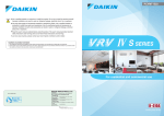
![Capitolato di gara [file ]](http://vs1.manualzilla.com/store/data/006110771_1-d2e80131dc42c63fd97368fc2ee33515-150x150.png)