1
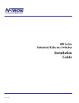
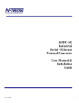
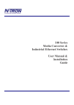
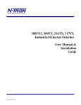
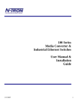
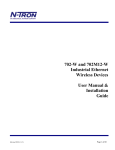
102MC
Industrial
Media Converter
User Manual &
Installation
Guide
8/2/2007
1
Industrial Media Converter Installation Guide
102MC
The 102MC is a 2 port unmanaged transparent media converter that converts 10Base-T copper to
10Base-FL half duplex fiber.
8/2/2007
2
Copyright, © N-TRON Corp., 2005
820 S. University Blvd., Suite 4E
Mobile, AL USA 36609
All rights reserved. Reproduction, adaptation, or translation without prior written permission from N-TRON Corp. is prohibited, except as
allowed under copyright laws.
Ethernet is a registered trademark of Xerox Corporation. All other product names, company names, logos or other designations mentioned
herein are trademarks of their respective owners.
The information contained in this document is subject to change without notice. N-TRON Corp. makes no warranty of any kind with regard to
this material, including, but not limited to, the implied warranties of merchantability or fitness for a particular purpose. In no event shall NTRON Corp. be liable for any incidental, special, indirect, or consequential damages whatsoever included but not limited to lost profits arising
out of errors or omissions in this manual or the information contained herein.
Warning
Do not perform any services on the unit unless qualified to do so. Do not substitute unauthorized parts or make unauthorized modifications to
the unit.
Do not operate the unit with the top cover removed, as this could create a shock or fire hazard.
Do not block the air vents on the sides or the top of the unit.
Do not operate the equipment in the presence of flammable gasses or fumes. Operating electrical equipment in such an environment constitutes
a definite safety hazard.
Do not operate the equipment in a manner not specified by this manual.
Safety Warnings
GENERAL SAFETY
WARNING: If the equipment is used in the manner not specified by N-TRON Corp., the protection provided by the equipment may be impaired.
Contact Information
N-TRON Corp.
820 South University Blvd.
Suite 4E
Mobile, AL 36609
TEL: (251) 342-2164
FAX: (251) 342-6353
Website: www.n-tron.com
Email: [email protected]
8/2/2007
3
ENVIRONMENTAL SAFETY
WARNING: Disconnect the power and allow to cool 5 minutes before touching.
ELECTRICAL SAFETY
WARNING: Disconnect the power cable before removing the enclosure top.
WARNING: Do not operate the unit with the top cover removed.
WARNING: Do not work on equipment or cables during periods of lightning activity.
WARNING: Do not perform any services on the unit unless qualified to do so.
WARNING: Do not block the air vents.
WARNING: Observe proper DC Voltage polarity when installing power input cables. Reversing voltage polarity can cause permanent damage
to the unit and void the warranty.
8/2/2007
4
PACKAGE CONTENTS
Please make sure the Serial over Ethernet package contains the following items:
1.
2.
102MC Media Converter
Product CD
Contact your carrier if any items are damaged.
INSTALLATION
Read the following warning before beginning the installation:
WARNING
Never install or work on electrical equipment or cabling during periods of lightning activity. Never connect or disconnect power
when hazardous gasses are present.
Disconnect the power cable before removing the enclosure top.
Do not operate the unit with the top cover removed
UNPACKING
Remove all the equipment from the packaging, and store the packaging in a safe place. File any damage claims with the carrier.
CLEANING
Clean only with a damp cloth.
SERVICING
Jumper J3 can be changed on the board to change the RJ45 copper port’s MDIX setting. See Connecting the Unit on page 8 for
more details.
8/2/2007
5
DIN-Rail Mounting
Install the unit on a standard 35mm DIN-Rail. Recess the unit to allow at least 5” of horizontal clearance for the fiber optic cable
bend radius.
To install the unit to 35mm industrial DIN-Rail, place
the top edge of the included mounting bracket on the back
of the unit against the DIN-Rail at a 15° angle as shown.
Rotate the bottom of the unit to the back (away from you)
until it snaps into place.
300-PM
900-PM
900-RM
8/2/2007
To remove the unit from the 35mm industrial DIN-Rail,
place a flat head screwdriver into the orange release clip
found at the bottom of the unit, and apply downward force
on the clip until it disengages from the bottom of the unit
from the DIN-Rail. Rotate the bottom of the unit towards
you and up at an approximate 15° upward angle to
completely remove the unit.
With the exception of the 524TX and
526FX2, all N-Tron™ products are designed
to be mounted on industry standard 35mm
DIN-Rail. However, DIN-Rail mounting may
not be suitable for all applications. We offer
three alternative mounting solutions: Our 300
Panel Mount Assembly (P/N: 300-PM) may
be used to mount a single 100 or 300 Series
unit to a panel or other flat surface. Our 900
Panel Mount Assembly (P/N: 900-PM) may
be used to securely mount our 100, 200, 300,
400, 500, or 900 Series products to a panel or
other flat surface; Our Rack Mount Assembly
(P/N: 900-RM) may be used to mount our
products to standard 19" racks.
6
FRONT PANEL
From Top to Bottom:
Green LED lights when Power is connected
RJ45 Port 10Base-T Connection
ACT
Activity LED for Fiber Optic Port
LNK
Link LED for Fiber Optic Port
RX
Fiber Optic Receiver Port
TX
Fiber Optic Transmitter Port.
NOTE: The RJ45 data port has two LED’s located at the left side of the connector. The top LED indicates
Activity (ACT), and the lower LED indicates Link (LNK) status.
LED’s: The table below describes the operating modes:
LED
Color
Description
GREEN
Power is Applied
OFF
Power is OFF
GREEN
10 Mb Link between ports
OFF
No Link between ports
GREEN
Data is active between ports
OFF
Data is inactive between ports
LNK
ACT
8/2/2007
7
APPLYING POWER (Top View)
Unscrew & Remove the DC Voltage Input Plug from the Power Input Header
Install the DC Power Cables into the Plug (observing polarity).
Plug the Voltage Input Plug back into the Power Input Header.
Tightening torque for the terminal block power plug is 0.22 Nm/0.162 Pound Foot.
Verify the Power LED stays ON (GREEN).
Note: Only 1 power supply must be connected to power for minimal operation. For redundant power
operation, V1 and V2 inputs must be connected to separate DC Voltage sources. This device will draw
current from both sources simultaneously. Use 16-28 gauge wire when connecting to the power supply.
Recommended 24V DC Power Supplies, similar to:
100VAC/240VAC:
N-Tron’s NTPS-24-1.3, DC 24V/1.3A,
8/2/2007
8
N-TRON SWITCH GROUNDING TECHNIQUES
The grounding philosophy of any control system is an integral part of the design. N-Tron switches are designed
to be grounded, but the user has been given the flexibility to float the switch when required. The best noise
immunity and emissions (i.e. CE) are obtained when the N-Tron switch chassis is connected to earth ground via
a drain wire. Some N-Tron switches have metal din-rail brackets that can ground the switch if the din-rail is
grounded. In some cases, N-Tron switches with metal brackets can be supplied with optional plastic brackets if
isolation is required.
Both V- legs of the power input connector are connected to
chassis internally on the PCB. Connecting a drain wire to
earth ground from one of the V- terminal plugs as shown here
will ground the switch and the chassis. The power leads from
the power source should be limited to 3 meters or less in
length.
As an alternate, users can run a drain wire & lug from any of the Din-Rail
screws or empty PEM nuts on the enclosure. When using an unused PEM
nut to connect a ground lug via a machine screw, care should be taken to
limit the penetration of the outer skin by less than 1/4 in. Failure to do so
may cause irreversible damage to the internal components of the switch.
Note: Before applying power to the grounded switch, you must use a volt
meter to verify there is no voltage difference between the power supply’s
negative output terminal and the switch chassis grounding point.
The use of shielded cables between devices is not required for most N-Tron devices (please consult the user
manuals for specific details). If the use of shielded cables is required, it is generally recommended to only
connect the shield at one end to prevent ground loops and interfere with low level signals (i.e. thermocouples,
RTD, etc.). Cat5e cables manufactured to EIA-568A or 568B specifications are required for use with N-Tron
Switches.
In the event all Cat5e patch cable distances are small (i.e. All Ethernet devices are located the same local
cabinet and/or referenced to the same earth ground), it is permissible to use fully shielded cables terminated to
chassis ground at both ends in systems void of low level analog signals.
8/2/2007
9
RJ45 CONNECTOR CRIMP SPECIFICATIONS
Please reference the illustration below for your Cat5 cable specifications:
8/2/2007
10
CONNECTING THE UNIT
For the 10Base-FL Fiber Optic port, remove both of the dust caps from the fiber optic connectors and
connect the fiber optic cables. The TX port on the local unit should be connected to the RX port of the far end
device, and the RX port should be connected to the TX port of the far end device.
For 10Base-T port, plug a Category 3 or better twisted pair cable into the RJ45 connector. Connect the
other end to the far end device. Verify that the LNK LED’s are ON once both the fiber and the copper are
linked. The MDIX mode of the 102MC can be changed using jumper J3 on the board. By factory default the
device is set up to use a straight through cable for a PC. Any N-Tron switch will automatically determine what
MDIX the 102MC is using and will connect it to the network.
Note: The 102MC is a transparent media converter. Both the fiber port and the copper port must be linked in
order for the unit to display any link status on the link LEDs. At least one of the two ports must be hard set to
10Base (if the fiber device is 10Base-FL then it is automatically set to 10Base).
TROUBLESHOOTING
1. Make sure the
(Power LED) is ON.
2. Make sure you are supplying sufficient current for the version chosen. Note: The Inrush current will
exceed the steady state current by ~ 2X.
3. Verify that Link LED’s are ON for both ports.
4. Verify cabling used between stations.
5. Verify that cabling is Category 3 or greater for 10Mbit Operation.
6. The 102MC is a transparent media converter, if one side isn’t linked properly both ports will not indicate
a valid link.
8/2/2007
11
SUPPORT
Contact N-TRON Corp. at:
TEL: 251-342-2164
FAX: 251-342-6353
www.n-tron.com
[email protected]
FCC STATEMENT
This product complies with Part 15 of the FCC-A Rules.
Operation is subject to the following conditions:
(1) This device may not cause harmful Interference
(2) This device must accept any interference received, including interference that may cause undesired
operation.
8/2/2007
12
KEY SPECIFICATIONS
Physical
Height:
Width:
Depth:
Weight:
DIN-Rail:
3.49"
2.01"
4.00"
0.75 lbs
35mm
Electrical
Redundant Input Voltage:
Input Current:
Inrush Current:
Input Ripple:
Input Wire Size:
10-30 VDC (Regulated)
80 mA @ 24VDC (Steady State)
7.3Amp/1.0ms @ 24VDC
Less than 100 mV
16-28 AWG
Environmental
Operating Temp:
Storage Temp:
Operating Humidity:
Operating Altitude:
-20oC to 70oC
-40oC to 85oC
10% to 90% (Non Condensing)
0 to 10,000 ft.
Shock and Vibration
Shock:
200g @ 10ms
Vibration/Seismic:
50g, 5-200Hz, Triaxial
Note: Unit must be Bulkhead mounted to achieve these levels.
Reliability
MTBF:
Network Media
10BaseT:
10BaseFL:
Connectors
10BaseT:
10BaseFL:
>2Million Hours
>Cat3 Cable
50/125 µm Fiber @ 850nm
62.5/125 µm Fiber @ 850nm
100/140 µm and 200 µm Fiber @ 850nm
One (1) RJ-45 Copper Port
SC or ST Duplex Port
Recommended Wiring Clearance:
Front:
2" (5.08 cm)
Top:
3" (7.62 cm)
Emissions and Safety Approvals:
FCC Part 15 Class A
8/2/2007
13
N-TRON Limited Warranty
N-TRON, Corp. warrants to the end user that this hardware product will be free from defects in workmanship and materials, under normal use
and service, for the applicable warranty period from the date of purchase from N-TRON or its authorized reseller. If a product does not operate
as warranted during the applicable warranty period, N-TRON shall, at its option and expense, repair the defective product or part, deliver to
customer an equivalent product or part to replace the defective item, or refund to customer the purchase price paid for the defective product. All
products that are replaced will become the property of N-TRON. Replacement products may be new or reconditioned. Any replaced or repaired
product or part has a ninety (90) day warranty or the remainder of the initial warranty period, whichever is longer. N-TRON shall not be
responsible for any custom software or firmware, configuration information, or memory data of customer contained in, stored on, or integrated
with any products returned to N-TRON pursuant to any warranty.
OBTAINING WARRANTY SERVICE: Customer must contact N-TRON within the applicable warranty period to obtain warranty service
authorization. Dated proof of purchase from N-TRON or its authorized reseller may be required. Products returned to N-TRON must be preauthorized by N-TRON with a Return Material Authorization (RMA) number marked on the outside of the package, and sent prepaid and
packaged appropriately for safe shipment. Responsibility for loss or damage does not transfer to N-TRON until the returned item is received by
N-TRON. The repaired or replaced item will be shipped to the customer, at N-TRON’s expense, not later than thirty (30) days after N-TRON
receives the product. N-TRON shall not be responsible for any software, firmware, information, or memory data of customer contained in,
stored on, or integrated with any products returned to N-TRON for repair, whether under warranty or not.
ADVANCE REPLACEMENT OPTION: Upon registration, this product qualifies for advance replacement. A replacement product will be
shipped within three (3) days after verification by N-TRON that the product is considered defective. The shipment of advance replacement
products is subject to local legal requirements and may not be available in all locations. When an advance replacement is provided and
customer fails to return the original product to N-TRON within fifteen (15) days after shipment of the replacement, N-TRON will charge
customer for the replacement product, at list price.
WARRANTIES EXCLUSIVE: IF AN N-TRON PRODUCT DOES NOT OPERATE AS WARRANTED ABOVE, CUSTOMER'S SOLE
REMEDY FOR BREACH OF THAT WARRANTY SHALL BE REPAIR, REPLACEMENT, OR REFUND OF THE PURCHASE PRICE
PAID, AT N-TRON'S OPTION. TO THE FULL EXTENT ALLOWED BY LAW, THE FOREGOING WARRANTIES AND REMEDIES
ARE EXCLUSIVE AND ARE IN LIEU OF ALL OTHER WARRANTIES, TERMS, OR CONDITIONS, EXPRESS OR IMPLIED, EITHER
IN FACT OR BY OPERATION OF LAW, STATUTORY OR OTHERWISE, INCLUDING WARRANTIES, TERMS, OR CONDITIONS OF
MERCHANTABILITY, FITNESS FOR A PARTICULAR PURPOSE, SATISFACTORY QUALITY, CORRESPONDENCE WITH
DESCRIPTION, AND NON-INFRINGEMENT, ALL OF WHICH ARE EXPRESSLY DISCLAIMED. N-TRON NEITHER ASSUMES NOR
AUTHORIZES ANY OTHER PERSON TO ASSUME FOR IT ANY OTHER LIABILITY IN CONNECTION WITH THE SALE,
INSTALLATION, MAINTENANCE OR USE OF ITS PRODUCTS. N-TRON SHALL NOT BE LIABLE UNDER THIS WARRANTY IF
ITS TESTING AND EXAMINATION DISCLOSE THAT THE ALLEGED DEFECT OR MALFUNCTION IN THE PRODUCT DOES NOT
EXIST OR WAS CAUSED BY CUSTOMER'S OR ANY THIRD PERSON'S MISUSE, NEGLECT, IMPROPER INSTALLATION OR
TESTING, UNAUTHORIZED ATTEMPTS TO OPEN, REPAIR OR MODIFY THE PRODUCT, OR ANY OTHER CAUSE BEYOND THE
RANGE OF THE INTENDED USE, OR BY ACCIDENT, FIRE, LIGHTNING, POWER CUTS OR OUTAGES, OTHER HAZARDS, OR
ACTS OF GOD.
LIMITATION OF LIABILITY: TO THE FULL EXTENT ALLOWED BY LAW, N-TRON ALSO EXCLUDES FOR ITSELF AND ITS
SUPPLIERS ANY LIABILITY, WHETHER BASED IN CONTRACT OR TORT (INCLUDING NEGLIGENCE), FOR INCIDENTAL,
CONSEQUENTIAL, INDIRECT, SPECIAL, OR PUNITIVE DAMAGES OF ANY KIND, OR FOR LOSS OF REVENUE OR PROFITS,
LOSS OF BUSINESS, LOSS OF INFORMATION OR DATA, OR OTHER FINANCIAL LOSS ARISING OUT OF OR IN CONNECTION
WITH THE SALE, INSTALLATION, MAINTENANCE, USE, PERFORMANCE, FAILURE, OR INTERRUPTION OF ITS PRODUCTS,
EVEN IF N-TRON OR ITS AUTHORIZED RESELLER HAS BEEN ADVISED OF THE POSSIBILITY OF SUCH DAMAGES, AND
LIMITS ITS LIABILITY TO REPAIR, REPLACEMENT, OR REFUND OF THE PURCHASE PRICE PAID, AT N-TRON'S OPTION. THIS
DISCLAIMER OF LIABILITY FOR DAMAGES WILL NOT BE AFFECTED IF ANY REMEDY PROVIDED HEREIN SHALL FAIL OF
ITS ESSENTIAL PURPOSE.
DISCLAIMER: Some countries, states, or provinces do not allow the exclusion or limitation of implied warranties or the limitation of incidental
or consequential damages for certain products supplied to consumers, or the limitation of liability for personal injury, so the above limitations
and exclusions may be limited in their application to you. When the implied warranties are not allowed to be excluded in their entirety, they will
be limited to the duration of the applicable written warranty. This warranty gives you specific legal rights which may vary depending on local
law.
GOVERNING LAW: This Limited Warranty shall be governed by the laws of the State of Alabama, U.S.A.
8/2/2007
14