1
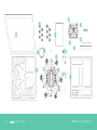
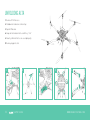
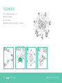
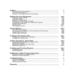
SETUP GUIDE
RE V ISION A | 7.24.2015
2
| SETUP GUIDE
WWW.FREEFLYSYSTEMS.COM
TABLE OF CONTENTS
04Disclaimer and Warning
23ALTA App
07Introduction
24Mapping Channels
12Unfolding ALTA
25Arm Enable Switch
13Folding ALTA
26Compass Calibration
14Installing a Radio Receiver
27Control Modes
16Failsafe and Loss of Signal
30Arming and Starting ALTA Motors
18Installing a Battery
32Tuning ALTA
20Status Light
33Setting Hover Throttle
21Orientation Lights
34Attaching a MōVI
22Configuration Jumper
3
| SETUP GUIDE
WWW.FREEFLYSYSTEMS.COM
DISCLAIMER AND WARNING
IMPORTANT - Please read this disclaimer and warning carefully
and review the ALTA User Manual prior to flight. If you have any
questions, please contact [email protected] prior to
using the ALTA . You can review the most current version of this
Setup Guide at www.freeflysystems.com/software-manuals/.
»» Always maintain a safe distance from ALTA when in use.
By using ALTA, you acknowledge that you have read, understand
and agree to this disclaimer. You agree that you are solely
responsible for your conduct while using ALTA, and for any
direct or indirect consequences that may result from its use.
You agree to only use ALTA for proper purposes that are in
accordance with local and airspace rules and regulations.
»» Only use propellers supplied by Freefly Systems
that are designed for use on ALTA .
»» ALTA is not a toy and should be operated with extreme care, as
improper operation can cause damage to property, serious
personal injury or death.
»» As with any multi-rotor, ALTA is a complex and technical machine.
Novice pilots should invest sufficient time on a flight simulator and
seek training from an experienced pilot prior to operation. A flight
simulator is no substitute for training with an experienced pilot,
particularly when it comes to learning how to safely operate ALTA .
Novice pilots should never fly without the supervision
of an experienced pilot.
»» Always check ALTA and its components for proper
and complete installation prior to operation.
4
| SETUP GUIDE
»» Never attempt to touch ALTA when the propellers are moving.
»» Never fly ALTA over or around people, power lines or other aircraft.
»» Always keep children and animals a safe distance away from ALTA
when in use and when changing ALTA’s configurations.
»» Always remove the propellers or power ALTA using a low-power
source when making a change to the configuration of ALTA to prevent
propeller strikes in the event of unintentional motor starts.
»» Always remove the Configuration Jumper when making changes to the
configuration of ALTA .
»» Always test ALTA with the propellers removed to make sure that
the motors are spinning in the correct direction and that the motor
assignment is correct with respect to the Synapse Flight Controller. If
either of these conditions are not met, ALTA will be
uncontrollable and dangerous.
»» It is your responsibility to perform a full system
check of ALTA prior to every flight.
»» It is your responsibility to learn how to safely operate ALTA and to
adhere to all applicable rules and regulations.
»» Fly at your own risk.
WWW.FREEFLYSYSTEMS.COM
LIMITATION OF LIABILITY
IN NO E VENT SHALL FREEFLY BE LIABLE TO BU YER FOR ANY INDIRECT,
CONSEQUENTIAL, PUNITIVE, INCIDENTAL, OR SPECIAL DAMAGES, OR
ANY DAMAGES WHATSOE VER RESULTING FROM THE USE OF ALTA OR
FROM LOSS OF USE, DATA OR PROFITS (HOWE VER CAUSED AND UNDER
ANY THEORY OF LIABILIT Y), E VEN IF FREEFLY HA S BEEN ADVISED OF
THE POSSIBILIT Y OF SUCH DAMAGES. IN NO E VENT SHALL FREEFLY ’S
LIABILIT Y FOR A PRODUCT (WHE THER A SSERTED A S A TORT CL AIM,
A CONTR ACT CL AIM OR OTHERWISE) E XCEED THE AMOUNTS PAID TO
FREEFLY FOR SUCH PRODUCT. NOT WITHSTANDING ANY THING HEREIN,
IN NO E VENT SHALL FREEFLY ’S LIABILIT Y FOR ALL CL AIMS ARISING OUT
OF OR REL ATING TO THIS AGREEMENT E XCEED THE AMOUNTS PAID BY
BU YER TO FREEFLY FOR PRODUCT IN THE L A ST T WELVE (12) MONTHS.
IN NO E VENT WILL FREEFLY BE LIABLE FOR COSTS OF PROCUREMENT
OR SUBSTITUTE GOODS BY BU YER. THE LIMITATIONS SE T FORTH HEREIN
SHALL APPLY TO ALL LIABILITIES THAT MAY ARISE OUT OF THIRDPART Y CL AIMS AGAINST BU YER. THESE LIMITATIONS SHALL APPLY
NOT WITHSTANDING ANY FAILURE OF ESSENTIAL PURPOSE OF ANY
LIMITED REMEDY.
Freefly shall not be liable for damages or injuries incurred directly
or indirectly from the use of ALTA including, but not limited to, the
following situations:
»» Failure of operator to follow proper instructions and safety warnings
found at www.freeflysystems.com/software-manuals/.
»» Failure of the operator to follow onboard safety
5
| SETUP GUIDE
warnings while using ALTA .
»» Failure of the operator to follow and comply
with local rules and regulations.
»» Failure of the operator to inspect ALTA and its
components prior to operation.
»» Failure of the operator to properly maintain and/or service
ALTA through an authorized Freefly Service Center
with genuine ALTA parts.
»» Use of third-party products on ALTA .
»» Use of ALTA in a physically or mentally
impaired capacity.
»» Use of ALTA without sufficient training.
»» Use of ALTA in unsafe conditions, including, but not limited to, bad or
severe weather, such as rain, wind, snow, lightning, dust storms, etc.,
or in areas of magnetic or radio interference, such as power stations,
broadcasting and cell phone towers,
government prohibited airspace, etc.
»» Improper operation, misjudgment or risky behavior
while using ALTA .
»» Infringement of third-party data, audio or video
rights recorded when using ALTA .
WWW.FREEFLYSYSTEMS.COM
BOOM NUMBERING AND PROP ROTATION (OVERHEAD VIEW)
BOOM 1 – Clockwise
BOOM 2 – Counter-Clockwise
BOOM 3 – Clockwise
BOOM 5 – Clockwise
BOOM 6 – Counter-Clockwise
6
| SETUP GUIDE
FORWARD
BOOM 4 – Counter-Clockwise
WWW.FREEFLYSYSTEMS.COM
INTRODUCTION
ALTA is a professional multi-rotor aircraft designed
for demanding cinematic, television, and photographic
applications. Within five minutes, ALTA can unfold from
its carrying case to flying some of the most advanced
cinema cameras on either the top or bottom of the
aircraft. The Synapse Flight Controller is purpose-built
for cinema use, yielding precise yet smooth control.
WARNING
Warnings are used to call attention to operating procedures which,
if not strictly observed, may result in personal injury or loss of life.
CAUTION
Cautions are used to call attention to operating procedures which,
if not strictly observed, may cause damage to equipment.
NOTE
Notes are used to highlight specific operating conditions or steps
of a procedure.
This Setup Guide has been prepared to highlight the
operation of basic airframe and flight control systems.
It is supplemental to the ALTA User Manual, which
contains all the information required to set up, operate
and maintain an ALTA system safely. Do not operate
ALTA without completely reading the User Manual
found at www.freeflysystems.com/software-manuals/.
7
| SETUP GUIDE
WWW.FREEFLYSYSTEMS.COM
ALTA OVERVIEW
1. GPS/Compass/Wi-Fi Module/microSD Card
6. Boom Retention Clip
2. Propeller
7. Isolator Cartridge
3. Boom
8. Motor
4. Boom Latch
9. Battery Pack (Not Included)
5. Inverted Landing Gear
10. Battery Retention Strap
TOP MOUNT CONFIGR ATION
8
| SETUP GUIDE
WWW.FREEFLYSYSTEMS.COM
17
18
16
11. Status Light
16. FPV Camera Mount
12. Orientation Light
17. Handle
13. Toad In The Hole Adapter
18. Power Leads
14. MōVI & Camera (Not Included)
15. Landing Gear (Not Included)
BOT TOM MOUNT CONFIGR ATION
9
| SETUP GUIDE
WWW.FREEFLYSYSTEMS.COM
10
| SETUP GUIDE
WWW.FREEFLYSYSTEMS.COM
UNBOXING ALTA
1. Case
10. Fasteners
2. ALTA
3. Case Lid Foam
4. Isolator Cartridges
a. (6) Teal (Installed)
b. (6) Black
a. (4) M3 × 8 Socket Head for
Toad In The Hole Male Adapter
b. (2) M3 × 8 Flat Head for Accessory Mount
11. Toad In The Hole Male Adapter
12. 5.5mm Wrench
13. Hex Drivers (1.5mm, 2.0mm, 2.5mm)
c. (6) Red
5. Documentation
6. USB-Futaba Power Cable
14. Accessory Mount
15. Double-Sided Tape
7. Inverted Landing Gear
8. Antenna Tubes
9. FP V Cables
a. Skyzone/BOSCAM
b. ImmersionRC/Fat Shark
c. Ready Made RC
11
| SETUP GUIDE
WWW.FREEFLYSYSTEMS.COM
UNFOLDING ALTA
1. Remove ALTA from case
2. Fold down all six boom retention clips
3. Open ALTA booms
4. Snap shut all six boom latches until they “click”
6. Visually confirm all latches are seated properly
5. Remove prop protectors
2
12
3
| SETUP GUIDE
4
5
6
WWW.FREEFLYSYSTEMS.COM
FOLDING ALTA
1. Secure props with prop protectors
2. Unlatch all six booms
3. Close ALTA booms
4. Fold up all six boom retention clips to secure booms
1
13
2
| SETUP GUIDE
3
4
WWW.FREEFLYSYSTEMS.COM
INSTALLING A RADIO RECEIVER
1
1. Locate the noted closeout panels used for receiver
installation (between booms 1 & 2 and 5 & 6)
2. Remove side closeout panel with radio
wires using a 1.5mm hex driver
3. Identify required wire
4. Feed wire through grommet
NOTE
5. Replace side closeout panel
6. Plug in receiver/satellite to wire
per the radio manufacturer’s
installation instructions
2
Refer to the user manual for Futaba
voltage telemetery installation
instructions.
3
4
S.BUS/S.BUS2
PPM
14
| SETUP GUIDE
5
DSM2/DSMX
WWW.FREEFLYSYSTEMS.COM
BINDING A RADIO RECEIVER
7. Attach receiver/satellite to exterior using the provided double sided tape:
a. Futaba & PPM receiver
b. Spektrum/JR
Refer to the instructions provided with your
radio controller to complete the binding process.
For Spektrum/JR radios, a receiver is required
to bind the satellites to a radio controller.
8. For Futaba receivers, feed antenna wires into
antenna tubes and zip tie to noted mounting location
9. Repeat 1-7 on opposite side for dual receivers
(only applies to Futaba and Spektrum/JR)
7a
15
7b
| SETUP GUIDE
8
WWW.FREEFLYSYSTEMS.COM
FAILSAFE AND LOSS OF SIGNAL
FUTABA S.BUS AND SPEK TRUM/JR DSM
When using Futaba receivers with S.Bus or S.Bus2, or using Spektrum
or JR receiver satellites with DSM2 or DSMX, the Synapse Flight
Controller can detect signal strength and a loss of signal event.
Setting failsafes in the receiver is not necessary, as failsafe behavior
is set in the ALTA App. The radio’s failsafe settings will not be used.
WARNING
Improperly set failsafe settings on PPM radio receivers can cause
unexpected flight behaviors if ALTA loses radio control signal.
After setting radio failsafe settings, ensure they are correct by
viewing the channel mapping parameters in the radio configuration
screen in the ALTA App, or viewing radio charts in the ALTA App.
Ensure that the radio commands behave as expected when the
radio controller is powered off.
PPM RECEIVERS
When using a receiver with a PPM output signal, the Synapse Flight
Controller will not automatically detect loss of signal and will follow
the radio controller failsafe commands typically set during the bind
process. Refer to your radio controller manual for information
on setting up failsafes.
16
| SETUP GUIDE
WWW.FREEFLYSYSTEMS.COM
WE RECOMMEND THE FOLLOWING FAIL SAFE SE T TINGS:
1. Throttle: Neutral
2. Pitch/Roll/Yaw: Neutral
3. Flight Mode Switch: Position Mode
4. Home Switch: Return to Home
3
2
1
4
POSITION
HEIGHT
MANUAL
LEF T STICK
17
| SETUP GUIDE
R.T.H.
RIGHT STICK
WWW.FREEFLYSYSTEMS.COM
INSTALLING A BATTERY
WARNING
See warning on page 19.
BOT TOM MOUNT
1. Place battery retention strap studs at the appropriate height for battery pack(s)
2. Adjust battery stops to fit battery pack(s)
CAUTION
See cautions on page 19.
3. Attach the single-hole end of the battery retention straps
to the studs
4. Place battery pack(s) on battery tray below handle
5. Tension and secure battery retention straps.
1
18
2
| SETUP GUIDE
3
4
5
WWW.FREEFLYSYSTEMS.COM
WARNING
Always secure battery packs with both battery retention straps.
TOP MOUNT
1. Adjust battery stops to fit battery pack(s)
CAUTION
2. Attach the single-hole end of the battery retention
strap to a stud on the landing gear
When plugging in battery packs, ensure the polarity is
correct. Positive is indicated by a red power lead, and
negative/ground is indicated by a black power lead.
Reversing polarity will damage ALTA’s electronics.
3. Place battery packs(s) in landing gear
4. Tension and secure battery retention straps
CAUTION
When installing two battery packs, ensure they are at a similar
state of charge (a full pack voltage difference less than 0.5V).
Plugging in two dissimilarly charged packs could cause one pack
to rapidly discharge into the other and damage the batteries or
cause a battery fire.
1
2
3–4
CAUTION
When using two battery packs, only use packs that are
identical in their capacity and at a similar condition. Using
a pack with another that is larger, or has many more
cycles, can damage the battery packs.
19
| SETUP GUIDE
WWW.FREEFLYSYSTEMS.COM
STATUS LIGHT
The rear-facing Status Light shows the status of ALTA as it
boots, arms and flies. The following table shows the different
meanings of the light in the various flight phases.
FLIGHT PHASE
LIGHT COLOR
MEANING
BOOTING
Flashing Red + White
Flight controller is booting
Flashing White
Flight controller is running and ready to arm
Flashing Red
Flight controller is running and not ready to arm
Solid Red
Flight controller boot unsuccessful
A RMED
Off
Ready for flight
FLIGHT - A LL MODE S
Solid Red
S TA NDBY
FLIGHT - P OSITION MODE
20
| SETUP GUIDE
Battery cell voltage below user-defined levels
Off
Nominal flight status
No errors
Solid White
Outside user-defined range, height or speed limits
Off
Nominal flight status
Height Hold inactive
Slow Flashing White
Height Hold active
Flashing Red
Battery cell voltage below user-defined levels
Off
Nominal flight status
Height Hold inactive
Position Hold inactive
Slow Flashing White
Height Hold or Position Hold active
Fast Flashing White
Height Hold and Position Hold active
Flashing Red
Battery cell voltage below user-defined levels
FLIGHT - M A NUA L MODE
FLIGHT - HEIGHT MODE
A flight controller error has occurred
WWW.FREEFLYSYSTEMS.COM
ORIENTATION LIGHTS
The boom-end mounted Orientation Lights indicate both the
orientation of ALTA in flight and the status of the individual
motor Electronic Speed Controllers (ESCs) during other
flight phases. The following table shows the different
meanings of the light colors in the various flight phases.
FLIGHT PHASE
LIGHT COLOR
MEANING
BOOTING
Blue
ESC booting
S TA NDBY
Flashing green
ESC booted normally
A RMED
User-defined
Nominal status
FLIGHT
User-defined
Nominal status
FIRM WA RE UPDATE
Blue then yellow
ESC firmware is updating
BOT TOM VIE W
21
| SETUP GUIDE
WWW.FREEFLYSYSTEMS.COM
CONFIGURATION JUMPER
A small jumper is used to prevent motor operation while configuring
radio mapping parameters. With the jumper in place, the motors may
operate, but channel mapping is prevented. With the jumper removed,
channel mapping may take place, but the motors will be turned off.
1. Locate the closeout panel where the jumper
is installed
2. Remove the side closeout panel with the
jumper using a 1.5mm hex driver
3. Remove or replace the jumper
4. Reattach the closeout panel
1
22
2
| SETUP GUIDE
3
WWW.FREEFLYSYSTEMS.COM
ALTA APP
The ALTA App is used to configure ALTA
parameters and to monitor ALTA’s status during flight.
NOTE
When making configuration changes with the ALTA App, wait three
seconds for the app to automatically save changes to ALTA.
To download the ALTA App, search for
“Freefly ALTA” in the App Store or on Google Play™.
23
| SETUP GUIDE
WWW.FREEFLYSYSTEMS.COM
MAPPING CHANNELS
To map channels, use the ALTA App. For complete information on
channel mapping, please refer to the ALTA User Manual.
1. Remove the Configuration Jumper (see page 22)
2. Power ALTA using a battery pack or by plugging in the included
USB-Futaba cable into an available port on a Futaba receiver
WARNING
Always ensure the Configuration Jumper is removed prior to
adjusting radio settings to prevent unintentional motor starts.
WARNING
Ensure proper channel mapping prior to flight. Incorrect mapping
can lead to immediate loss of control.
3. Open the ALTA App and connect to ALTA
4. Open Configurations > Radio
5. Open each ALTA function and adjust the channel to the
desired channel number, and use the toggle to invert
the orientation of a control
6. Ensure proper channel selection by moving the control
input on the radio controller and verifying the displayed
graph in the ALTA App responds correctly
ONCE CHANNEL S ARE M APPED
7. Remove the battery or USB-Futaba cable from ALTA
8. Replace the Configuration Jumper
24
| SETUP GUIDE
RADIO
SETUP
ADJUSTMENTS
CONTROLLER
FUTABA
CHANNEL MAPPING
–
–
–
PITCH
ROLL
YAW
–
–
–
THROTTLE
MODE
HOME SWITCH
–
–
–
VELOCITY
CLAMP
CLIMB RATE
CLAMP
ARM ENABLE
SWITCH
WWW.FREEFLYSYSTEMS.COM
ARM ENABLE SWITCH
The optional Arm Enable Switch allows for added safety while
working around and flying ALTA by disallowing arming during
ground handling or disarming during flight. To set up an Arm Enable
Switch, refer to Mapping Channels or the ALTA User Manual.
SWITCH POSITION
ARMING
DISARMING
1
Possible
Not possible
2 (MIDDLE)
Possible
Possible
3
Not Possible
Possible
If used, the Arm Enable function should be
mapped to a three-position switch.
25
| SETUP GUIDE
WWW.FREEFLYSYSTEMS.COM
COMPASS CALIBRATION
ALTA features a highly sensitive 3-axis magnetometer that measures the
earth’s magnetic field to infer heading. Occasionally, the compass will require
calibration, especially when traveling between different geographic locations.
TO PERFORM A COMPA SS CALIBR ATION:
1. Secure a battery onto ALTA (see page 18-19)
2. Plug in the battery
3. Open the ALTA App
WARNING
Verify ALTA is disarmed prior to performing a compass
calibration. To ensure ALTA does not arm, set the Arm
Enable Switch (if available) to disable, and remove the
Configuration Jumper.
NOTE
It is recommended to use two people to perform the compass
calibration as it requires handling and rotating ALTA. Perform
calibration without a payload attached.
4. Select Configurations > More > Compass
5. Under Calibration, select Start Manual
6. Follow the on-screen instructions
26
| SETUP GUIDE
NOTE
Ensure a microSD card is installed in the GPS/compass module
prior to performing compass calibration.
WWW.FREEFLYSYSTEMS.COM
CONTROL MODES
ALTA has three primary flight control modes: Manual Mode, Height Mode,
and Position Mode. They are selected with the Mode Switch.
CAUTION
Always neutralize control inputs when switching
between control modes.
MANUAL MODE
In Manual Mode, ALTA will only stabilize its attitude. At neutral
control input (middle pitch and roll stick position), ALTA will
attempt to remain level. Throttle control is direct.
HEIGHT MODE
Height Mode changes the throttle stick behavior to command climb and
descent rates. The higher the throttle stick position, the faster ALTA will climb.
Conversely, the lower the throttle stick position, the faster ALTA will descend.
When the throttle stick is centered, ALTA will enter Height Hold. In
Height Hold, ALTA will maintain a target altitude and try to correct
for drift. If a disturbance moves ALTA away from this target altitude,
ALTA will climb or descend to return to the target altitude.
27
| SETUP GUIDE
WWW.FREEFLYSYSTEMS.COM
CONTROL MODES (CONTINUED)
POSITION MODE
RE TURN-TO-HOME
Position Mode changes the pitch/roll stick behavior to command
ground speeds. Pitch and roll stick deflection will command fore/
aft and left/right ground speeds respectively. Controlling altitude in
Position Mode is the same as in Height Mode.
Return-To-Home Mode will command ALTA to fly back to the starting
point of the flight or the last defined Home Point. When ALTA first
acquires a GPS position, it sets this as the Home Point of the flight.
The Home Switch on your radio controller can also be used to set a
new Home Point. See Channel Mapping in the User Manual for more
information on setting up the Home Switch.
With pitch and roll controls centered, ALTA will enter Position Hold. In
Position Hold, ALTA will maintain its position over a given point on the
ground and correct for disturbances.
Position Mode requires a strong GPS signal. If a weak signal is
present, ALTA will not enter Position Mode, and if the GPS signal
degrades while in Position Mode, ALTA will automatically revert to
Manual Mode.
AUTOL AND
The Autoland function will command ALTA to hover for 10 seconds
and will then land in place. It only occurs if Autoland is selected as the
Loss of Signal (LOS) event in the ALTA App, or at the end of an LOS
Return-to-Home (RTH) event. If ALTA is above the app-configurable
Safe Height setting, ALTA will first descend to it at the Maximum
Descent Rate. After reaching this height, ALTA’s descent will slow to
the Autoland Descent Rate.
RTH can be initiated manually by the Home Switch or be initiated with
an LOS event.
When initiated with the Home Switch, ALTA will fly back to the Home
Point, and the pilot will maintain control of ALTA’s altitude the entire
time. ALTA will not autoland if adequate signal is detected. The pilot
can cancel the RTH procedure by commanding a pitch or
roll command.
During an LOS event, ALTA will first check its current altitude against
Safe Height. If it is lower, it will climb to Safe Height, and if ALTA is
above Safe Height, it will remain at its current altitude. Next, ALTA will
fly back to the home position at the RTH Speed set in the ALTA App.
Finally, upon reaching the home position, ALTA will begin Autoland.
CAUTION
Flight using Position Mode in areas of degraded GPS signal, such as near buildings
or under dense tree cover, is not recommended. The reversion to Manual Mode can
sometimes cause abrupt changes in flight behavior.
28
| SETUP GUIDE
WWW.FREEFLYSYSTEMS.COM
RADIO LOSS OF SIGNAL
SAF E H E I GH T I S U S E R D E F I NE D
ALTA App > Configurations > Safety > Safe Height
29
| SETUP GUIDE
WWW.FREEFLYSYSTEMS.COM
ARMING AND STARTING ALTA MOTORS
TO ARM ALTA
1. Ensure ALTA is powered on and is in Standby Mode
2. Select Manual Mode using the radio controller’s mode switch
3. Set the radio controller’s home switch to the middle position
4. Set the radio controller’s arm enable switch to enable arming
5. Hold full low throttle and full left yaw
6. Ensure Status Light extinguishes and Orientation Lights
change to the colors defined in the app
5
3
2
HEIGHT
MANUAL
30
| SETUP GUIDE
L
4
POSITION
MODE 02
R
ENABLE ARM
RTH OFF
MODE 01
ENABLE BOTH
ENABLE DISARM
L
R
WWW.FREEFLYSYSTEMS.COM
TO START ALTA MOTORS
TO STOP ALTA MOTORS AND DISARM
1. Ensure ALTA is armed
1. Set Arm Enable Switch to Enable Disarm
2. Hold full low throttle and full right yaw
2. Ensure Mode Switch is set to Manual Mode
3. Ensure ALTA motors spin up
3. Hold full low throttle and full left yaw
4. Ensure ALTA Status Light flashes white and Orientation
Lights flash green
WARNING
Always check the ALTA and its components prior to operation.
Always maintain a safe distance from the ALTA when in use.
Never attempt to touch the ALTA when the propellers are moving.
2
WARNING
CAUTION
Motors can be disabled in flight if
the disarming procedure
is followed.
1
MODE 02
Do not attempt to disarm motors in Height or
Position Modes.
2
MODE 02
ENABLE ARM
L
R
ENABLE BOTH
L
R
ENABLE DISARM
MODE 01
L
R
2
MODE 01
POSITION
HEIGHT
L
R
MANUAL
31
| SETUP GUIDE
WWW.FREEFLYSYSTEMS.COM
TUNING ALTA
ALTA comes pre-tuned for a wide variety of payloads and flying conditions.
Generally, additional tuning is not required to fly ALTA, and additional tuning
will only need to take place if more customization of control feel is desired. For
more information on tuning parameters, refer to the ALTA User Manual.
32
| SETUP GUIDE
WARNING
Tuning can change the fundamental flying characteristics of ALTA .
It is possible for ALTA to become unstable or even uncontrollable
if values are set too high or too low. Only change tuning parameters
in small increments and with caution. Always test new tuning
configurations in open areas away from people or obstacles.
WWW.FREEFLYSYSTEMS.COM
SETTING HOVER THROTTLE
NOTE
Hover Throttle is an app-configurable parameter that adjusts ALTA’s thrust at
center throttle stick and ensures ALTA does not climb or descend at the center stick
position while flying in Manual Mode. A Hover Throttle setting that is too high or too
low can cause ALTA to climb or descend when switching between Manual Mode
and Height Mode.
Adjust the Hover Throttle setting by entering a stable hover in Manual Mode. Note the
stick position, or have an assistant view the radio chart in the ALTA App to determine
stick position. If ALTA hovers with the stick below neutral, decrease the Hover
Throttle until ALTA hovers with neutral stick input. If ALTA hovers with the stick
above neutral, increase the Hover Throttle until ALTA hovers with neutral stick input.
IF
THEN
IF
THEN
Hover Throttle will need to be adjusted when changing the
overall weight of the system, or when moving between very
different elevations.
NOTE
The ALTA App does not allow Hover Throttle adjustments while
ALTA is flying.
COMPLETE
DECREASE
Hover Throttle
Bring ALTA to a hover
IF
THEN
INCREASE
Hover Throttle
33
| SETUP GUIDE
WWW.FREEFLYSYSTEMS.COM
ATTACHING A MōVI
A MōVI can be attached to either the top or bottom of the
ALTA via the Freefly Toad In The Hole (TITH) Quick Release.
ALTA comes pre-configured for bottom mounting a MōVI.
BOT TOM MOUNT
1. Prepare your MōVI for bottom-mount flight (see MōVI manual)
a. Attach landing gear
b. Install TITH receiver on MōVI
2. Connect MōVI to bottom Toad
2
34
| SETUP GUIDE
WWW.FREEFLYSYSTEMS.COM
CAUTION
Top mounting is not supported by the MōVI M10.
ADDING A TITH TOP MOUNT
1. Prepare your MōVI for top-mount flight
a. Remove landing gear (see MōVI manual)
b. Install TITH receiver on MōVI (see MōVI manual)
2. Connect and secure the supplied inverted landing gear to the bottom Toad
3. Remove the four flathead M3×6 bolts that secure the top handle
4. Attach the supplied Toad to the top plate using the four M3×8 bolts provided
5. Connect MōVI to the top Toad
5
3
4
2
35
| SETUP GUIDE
WWW.FREEFLYSYSTEMS.COM
W W W.FREEFLYSYSTEMS.COM
MōVI is a registered trademark in the U.S. Pat. & Tm. Office. FREEFLY, the wing logo, and A LTA are trademarks of Freefly Systems Inc.
Apple and the Apple logo are trademarks of Apple Inc., registered in the U.S. and other countries. App Store is a service mark of Apple Inc.
Google Play is a trademark of Google, Inc.
770-00041 07-15