1
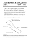
HR150 SERIES DEHYDRATOR USER MANUAL Bulletin AE01B-A0595-001 Rev: A © 2014 CommScope, Inc. All rights reserved Page 1 of 12 (06/14) HR150 SERIES DEHYDRATOR USER MANUAL Contents Section 1 1.1 General Information............................................................................................................................................................. 3 Introduction .............................................................................................................................................................................. 3 Section 2 Safety Information ............................................................................................................................................................... 3 Section 3 Equipment ............................................................................................................................................................................ 4 3.1 Supplied Equipment ................................................................................................................................................................. 5 Section 4 Description ........................................................................................................................................................................... 6 Section5 Installation ........................................................................................................................................................................... 6 5.1 Unpacking ................................................................................................................................................................................. 6 5.2 Mounting .................................................................................................................................................................................. 7 5.2.1 19” Rack Mounting ................................................................................................................................................................... 7 5.2.2 Wall Mounting .......................................................................................................................................................................... 7 5.3 Electrical Connections .............................................................................................................................................................. 7 5.3.1 Power Connections ................................................................................................................................................................... 7 5.3.2 Power Connections ................................................................................................................................................................... 8 5.4 Pneumatic Connections ............................................................................................................................................................ 8 5.4 Operation ................................................................................................................................................................................. 8 5.6 Alarms ....................................................................................................................................................................................... 8 Section 6 Corrective Maintenance and Spare Parts ............................................................................................................................ 9 Section 7 Outline ............................................................................................................................................................................... 10 Section 8 Customer Service ............................................................................................................................................................... 11 8.0 Introduction ............................................................................................................................................................................ 11 8.1 In Case of Trouble ................................................................................................................................................................... 11 8.2 Initial Steps by CommScope ................................................................................................................................................... 11 8.3 Repair Center Process ............................................................................................................................................................ 11 Page 2 of 12 HR150 SERIES DEHYDRATOR USER GUIDE MANUAL Section 1 1.1 General Information Section 2 Introduction Safety Information Make sure that the information in this document has been understood by the persons performing the procedures: The HR150 is a heat regenerative air dryer. It utilizes redundant compressors and drying canisters to insure a reliable flow of dry air for pressurization of air cable. The canisters automatically regenerate, eliminating the maintenance associated with typical desiccant dryers. The HR150 must be located such that only authorized personnel have access. CAUTION: The HR150 utilizes heat to regenerate the drying canisters. Mount the HR150 at the top of the equipment rack if possible. Should be placed in the top of the equipment rack with nothing mounted above it. Page 3 of 12 Electrical Hazard! Unplug power cord before servicing unit. Let unit cool before removing cover. HR150 SERIES DEHYDRATOR USER MANUAL Section 3 Equipment Output Pressure 3 kPa (.44 psig), nominal Maximum Flow Rate 150 lph (5.3 scfh) Safety Valve 7 kPa (1.0 psig) Output Air Dew Point ‐45°C (‐50°F) , nominal Desiccant Regeneration Automatic by heat Regeneration Phase Interval 2 hours heat / 5 hours operation Alarms low pressure, high pressure, high humidity (optional) Low Pressure Alarm 1.5 kPa (0.22 psig) High Pressure Alarm 4.5 kPa (0.65 psig) High Humidity Alarm 10% RH LED Indications Power on, Alarm codes Acoustic Noise 50 dBA Enclosure Degree of Protection IP20 Operating Temperature ‐5ºC to +50ºC (+23ºF to + 122ºF) Storage Temperature ‐40ºC to +70ºC (‐40ºF to +158ºF) Power Supply Std. ‐48 / ‐60 V DC Power Consumption <45 W Dimensions 2 RU (428 mm x 87 mm x 234 mm) (16.85 in x 3.43 in x 9.21 in) European Community Directives CE Safety Normative ETSI EN 60950‐1 ANSI/UL 60950‐1 CAN/CSA‐C22.2 No. 60950‐1‐07 Electromagnetic Compatibility Normative ETSI EN 301 489‐1 ANSI CFR 47 Part 15 Quality Assurance Std. ISO 9001 Weight 4.8 kg (10.58 lbs) Output Pneumatic Connector 4 each 3/8” Compression Fittings Page 4 of 12 HR150 SERIES DEHYDRATOR USER GUIDE MANUAL 3.1 Supplied Equipment Item QTY Description A 1 HR150 Dehydrator B 2 Mounting Brackets B1 6 M4x10 PPH Screws, SST, Pass B2 6 M4 Flat Washer, SST, Pass C 1 Power Cable D 30.5 m 100 ft 9.5 mm (3/8”) Output Tubing Additional Accessories (sold separately) HR150‐KIT‐ETSI HR150 ETSI N3 RACK BRACKETS KIT HR150‐KIT‐ACDC HR150 AC TO 48 V DC POWER CONVERTER KIT Page 5 of 12 HR150 SERIES DEHYDRATOR USER GUIDE MANUAL Section 4 Section5 Description 5.1 The HR150 dehydrator system is designed for continuous automatic operation. It is a heat regenerative desiccant dehydrator designed to operate on ‐48 / ‐60 V DC. The desiccant automatically regenerates by periodic heating and requires no scheduled maintenance. It will supply up to 150 liters per hour (5.3 scfh) of air with a dew point of better than –45°C (–49°F) at a nominal pressure of 3 kPa (0.44 psig). Unpacking The HR150 is designed for mount in a standard 19” equipment rack and has an option for ETSI N3 rack‐mounting with adapter plates (sold separately). The HR150 requires 2 rack units to mount. Installation J2 Alarm Connection 4 OUTPUT PORTS ‐48/‐60 DC POWER CONNECTOR Dry air is supplied to the transmission lines by four independent outlets located on the rear of the chassis. The HR150 includes all necessary brackets and electrical terminations to successfully install the unit in a site. Ambient air is drawn through desiccant beds by two low power diaphragm compressors. The adsorbent material in the desiccant canisters removes moisture from the ambient air prior to passing it through the internal manifold where the system pressure and humidity level (optional) is monitored. Installation of the HR150 requires the following tools: System pressure dictates demand and the HR150 will respond by changing the speed of the compressors allowing the dehydrator to function without pressure switches or regulators. This increases compressor life and overall unit reliability. Page 6 of 12 #1 and #2 Phillips head screw drivers Wire cutters and wire strippers for alarm terminations HR150 SERIES DEHYDRATOR USER MANUAL 5.2 Mounting enough clearance for the tubing and electrical connections. CAUTION: The HR150 utilizes heat to regenerate the drying canisters. Mount the HR150 at the top of the equipment rack. The heat created by the HR150 is dissipated out of the top and side of the dehydrator. DO NOT mount any equipment above the HR150. 5.2.1 Secure the unit to the wall using appropriate fasteners for the wall material. The hardware for mounting to the wall is not included. 19” Rack Mounting 5.3 Caution: The ON/OFF switch on the front must be switched off prior to disconnecting the dehydrator from the power supply prior to servicing. Attach the supplied rack brackets with the included screws to the front mounting holes for installation in a standard 19” equipment rack as illustrated below. The hardware necessary for mounting to the equipment rack is not included A protective earth terminal is available through the power connector J1 and is marked by the Earth Ground symbol. 5.2.2 Electrical Connections Additionally, there is an external ground stud that can be used for additional electrical protection. Wall Mounting 5.3.1 Power Connections Verify that the power supply is the correct type and rated voltage prior to connecting the HR150. See power ratings label on rear side of the dehydrator. The power cable comes pre‐terminated for connection to J1 on the rear of the dehydrator. The HR150 incorporates reverse polarity protection. If the unit does not power up when connected to the DC supply, verify polarity and correct if necessary. The supply end of the Install the standard 19” rack brackets on the rear of the chassis with the included screws as illustrated below. The brackets will provide Page 7 of 12 HYDRATOR USER MANU UAL HR150 SERIES DEH powerr cable is left un‐terminated tto accom mmodate any tyype of power ssupply. If the proper DC pow wer supply volttage is ected to the dehydrator and tthe power conne switch h is turned on b but the unit faiils to operate, verify the polarity. If the polarity is incorrect, d then re‐conne ect to the have it reversed and drator. The HR dehydrators aare equipped dehyd with reverse polarityy protection, but will not operatte under reverrse polarity. The fiirst compresso or will start and d air will begin ng to the transsmission line(s)). flowin Polarity for the pow wer cable is: Red – Positive – Negative Black – White ‐ Ground If thiss is a new installation, the traansmission lines m must be purgeed by creating aa small leak at the faar end of the trransmission lin nes and allowing the dehydrrator to pump dry air through them. 5.3.2 nimum of threee air volume exxchanges is A min requirred. If the insttallation is locaated in a very humid d area, up to tw welve air exchanges may be necesssary to properrly purge the trransmission line. TThe time, in ho ours, necessaryy to exchange the aiir one time is b based on the to otal air volume e (V) off the waveguide and antennaa system. Purgin 50, where V is ng time (hourss) = (3 x V) / 15 line vvolume in literss At thee conclusion off the purging ccycle, close the far en nd of the transmission lines. 5.6 Alarm m Connections Alarm m wiring will need to be provid ded by the custom mer at the installation site. 5.4 Pneum matic Connectiions The HR150 has a quaantity of four 9 9.5 mm (3/8 mpression fittings located on n the rear of in) com the ch hassis. The deh hydrator is ship pped with one port o open to ambien nt air. The other three ports are plu ugged with pre essure caps in o order to preven nt air from esccaping from the ese ports when not in use. In order to use th hese onal ports, sim mply remove th he pressure additio caps. 5.4 ation Opera Conne ect the included tubing to an open port on the rear of the unit. All unused po orts must be ed with pressure caps. Turn on the power plugge switch h located on the front face. TThe LED will illumin nate. Page 8 of 12 Alarm ms The H HR150 is equipped with an LEED on the frontt panel for a visual indication of alarm conditions.. A greeen LED indicates all is well with the dehyd drator. A solid or blinking am mber LED indicaates a problem m with the dehyydrator. HR150 SERIES DEHYDRATOR USER MANUAL Blinks Alarm Solid Amber System Failure 1 High Humidity (optional) Low Pressure High Pressure 2 3 Description Indicates a failure of the controller. Replacement will be necessary. Indicates output air is above 10% RH. This can be caused by long storage periods and should clear in the first 24 hours of operation. Indicates a system pressure lower than alarm threshold. Indicates a system pressure higher than alarm threshold. Section 6 If multiple alarms exist at the same time, they will blink in sequence with approximately two seconds between. ALARM SYMBOLS Front of Chassis ALARM OUTPUT WIRES COLORS BLACK (NO) WHITE (COM) RED (NC) Rear of Chassis Page 9 of 12 Corrective Maintenance and Spare Parts The HR150 is designed to be maintenance free. If you experience any issues with the HR150, please contact CommScope. See Section 8 for additional information. HR150 SERIES DEHYDRATOR USER MANUAL Section 7 Outline Outline without mounting brackets Outline for 19’’ rack and wall mounting Outline side view Outline side view wall mounting Page 10 of 12 HR150 SERIES DEHYDRATOR USER GUIDE MANUAL Section 8 8.0 Customer Service From North America Introduction CommScope provides in‐warranty and out‐of‐ warranty repairs as well as dehydrator and compressor overhauls from several Repair Centers. Coordination of these services is provided through the nearest Sales Office or Customer Service Center. The Center is also prepared to help you with the following: 8.1 International 8.2 High Humidity Alarm Unit Will Not Power Up Initial Steps by CommScope The first step you should take if trouble develops using a dehydrator is to read the operators manual and follow the trouble shooting procedures given in it. Symptom Potential Solution High Pressure Alarm Internet: www.commscope.com email: #[email protected] When your call or fax communication is received, the CommScope staff will work with you to pinpoint the possible cause of trouble. If the pressurization equipment is suspect, they will: In Case of Trouble Low Pressure Alarm Telephone: +1‐779‐435‐6500 Fax Number: +1‐779‐435‐8579 Web Access Technical Assistance Troubleshooting Repairs Loaner Units Spare Parts Installation Materials System Accessories Pump Not Running Telephone: 1‐800‐255‐1479 Fax (U.S.A.): 1‐800‐349‐5444 Cycle power of the unit Verify pumps are connected to PCB Open output port and verify pump speed increases Unused output port not capped Transmission line open/leaking Internal tubing disconnected / leaking Very small system volume; allow unit pressure to settle over 20 minutes Leaking desiccant canister end plate Insufficient system purge DC Power polarity may be reversed Loose or disconnected wire inside of the unit 8.3 ask for your unit Model Number and Serial Number check the warranty status of the unit advise the availability of a loaner unit provide an estimate of the cost for inspection and repairs, if the unit is out–of– warranty fax a Return Material Authorization Sheet to you Repair Center Process A method of Payment must be provided prior to issuing of RMA regardless of warranty status. IN–WARRANTY REPAIR: This CommScope pressurization product carries a warranty of one year. Warranty details are available on our web page. If your unit falls within its warranty period, inspection and repairs will be performed at no charge and the unit will be promptly returned to you. If a warranty unit is deemed no problem found an inspection fee and freight will be charged to the customer. If the steps in the manual do not identify and remedy the problem, then contact a CommScope Customer Service Center for 24– hour telephone assistance. Record the Model Number (e.g. HR150) and Serial Number from the product label, as you will be asked for these when you call. Two main locations are currently available to help: OUT–OF–WARRANTY REPAIR: We will inform you with the cost of repair and obtain your approval to proceed with repairs or, if you elect not to have the unit repaired, your instructions on disposition of your unit. When repairs are complete, we will return your unit and invoice you for the inspection charge, materials used for the repair and labor applied to complete the repair. If you elected not to repair the unit, we Page 11 of 12 HR150 SERIES DEH HYDRATOR USER MANU UAL will invvoice you for tthe inspection and freight charge e if unit is to be e returned. LOANER UNITS: Loaner units may be available n your system from tthe repair centter to maintain while repairs are beiing performed. If you feel eed a loaner, p please contact us at one of you ne the co ontact numberss. If a loaner u unit is availab ble, a P.O. for tthe full value o of the unit must b be issued priorr to shipment. Also contact us when the loaner iis ready to be rreturned so we can issue a N NEW RMA num mber to that w identiffy your return and create the e appropriate credit to your account. Damages to o loaner will ducted from th he P.O. be ded PACKING INSTRUCTIONS: Pack you ur unit ely for shipmen nt to the Repaiir Center. If secure you re eceived a loane er unit, we suggest you use the bo ox and packing materials to re eturn your unit. O Otherwise we h have factory paacking materrials available for a nominal fe ee. Enclose a completed copy of this form inside e the box and clearlyy mark your Co ompany Name and RMA: XXXXX XXX on outside of the box. Ad ddress the box to the following Ship p–To Address: mScope Pressurrization Service e Center Comm RMA# # XXXXXXX 11312 2 S. PIPELINE RD D. EULESSS, TX. 76040‐6 6629 Please e note, Units re eceived with Biologgical/animal co ontamination w will be return ned unrepaired d or scrapped after notificcation and you u will be invoicced for inspecction and freigght. CONTA ACT NUMBERSS: If you have aany questions about the repair pro ocess or status of your unit, e contact us dirrectly through one of the please follow wing methods – – Telephone (below) 8.4 TEL: 817‐86 64‐4150 817‐86 64‐4155 FAX: 817‐86 64‐4179 RoHS Inquiries quiries on RoH HS please contaact the For inq follow wing: Comm mScope Inc. Corke Abbey, Bray C Co., n, Ireland Dublin Attn: LLegal Department Paage 12 of 12