1
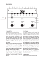
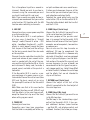
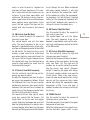
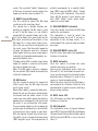
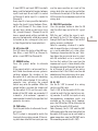
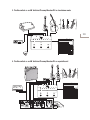
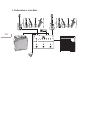
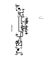
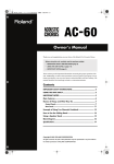
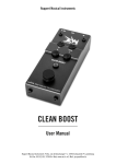
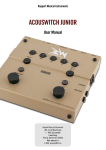
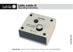
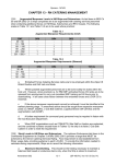
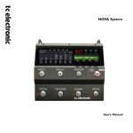
Ruppert Musical Instruments
TM
User Manual
Congratulations!
With the Basswitch IQ DI you have pur‑
chased a high‑quality piece of musical
equipment that will open up new dimen‑
sions in bass-signal amplification and
routing and give you the confidence that
you are adequately prepared for any situ‑
ation, be it in live performance or in a re‑
cording studio.
When developing the Basswitch IQ DI we
focused on the needs and wishes of the
professional bass player who is not will‑
ing to compromise on either sound or the
technical quality of the equipment. The
Basswitch IQ DI is manufactured, assem‑
bled and tested in Germany to the high‑
est quality standards using only the best
brand components available to ensure
optimal treatment of the electrical signal
from your instrument.
Thanks to its variable input impedance,
the Basswitch IQ DI is an all-rounder,
equally suitable for electric and acoustic
instruments. Whether the signal comes
from a magnetic or a piezo pick-up, the
high-end preamp of the Basswitch IQ DI
will ensure that their specific characteris‑
tics are uncompromised.
The Basswitch IQ DI has been designed to
offer bass players an „all-in-one” solution
whether used in stand-alone mode or as
the control centre of a pedal-board. It is
an A/B-input switcher, a high-end pre‑
amp, a clean booster, a parametric EQ, an
FX loop switcher and last but not least a
professional‑quality D.I. box. It is the only
product on the market that provides all
these functions and potential applications
in a single compact unit. The Basswitch
IQ DI is a Swiss Army knife that should be
part of the equipment of every demanding
bass player.
Please take your time to read this user
manual carefully before you start using
your Basswitch IQ DI. You will find lots of
useful information on the pedal and the
various ways it can be used. Keep this user
manual carefully so that you can consult it
at any time.
Your Basswitch IQ DI package contains
the following items:
- Basswitch IQ DI
- Optimised connector for the power sup‑
ply socket
- 4 plates for mounting on a pedal-board
etc.
- User manual
Please check that all these items are there
as soon as you unpack. Should something
be missing, please contact your autho‑
rised dealer.
The Basswitch IQ DI is built to last, but
if you nonetheless experience problems
or have any questions do not hesitate to
contact us.
I wish you every success with your Bass‑
witch IQ DI.
Yours,
Jacques Ruppert
P.S.: On our website www.basswitch.com you can find practical examples of how you can use your Basswitch IQ
DI and a whole range of sample settings for the parametric EQ – a treasure house for all sorts of bass sounds
that we will go on expanding!
Summary
Introduction
4
Description
6
Examples of possible set‑ups
13
Tech Talk
15
Technical data
18
Introduction
Why a specific preamp-/looper-/DI-pedal
for bass instruments? The reasons are ob‑
vious: the frequency range of bass instru‑
ments goes from very deep fundamentals
(e.g. 30.87 Hz for low B or 41.20 Hz for low E
on an electric bass) to very high overtones
that have a crucial impact on the timbre
of the bass instrument even though they
are approaching the upper limits of the
audible spectrum (from 18 Hz to 20 KHz).
On top of this, bass instruments have a
characteristic attack with a very steep ini‑
tial transient followed by a weak electri‑
cal signal. These characteristics of bass
signals make enormous demands on the
electronics, with the result that the han‑
dling of bass signals by most equipment
is unsatisfactory and inconsistent in qual‑
ity. Only equipment specifically designed
for the purpose is able to handle such a
demanding signal pattern adequately. The
advantage of the Basswitch IQ DI, which
meets these demands, is that it can also
be used in many other areas (e.g. to handle
the signals from acoustic instruments).
Functions and applications overview
- The Basswitch IQ DI as A/B input
switcher
Input „Instrument A” allows you to con‑
nect either a low‑impedance instrument
(e.g. passive or active electric bass) or a
high‑impedance instrument (e.g. piezopickup of an electric bass or double bass
or other acoustic instruments without
preamp). Input „Instrument B” allows you
to connect a second instrument. The A/B
footswitch permits toggling between the
two inputs, whereby the signal from in‑
put A is routed to Channel A of the pedal
and the signal from input B is routed to
Channel B. If no cable is connected to the
„Instrument B” input, the signal from In‑
strument A can be routed to Channel A or
Channel B by using the A/B footswitch.
- The Basswitch IQ DI as high-end
preamp with parametric EQ
Channel A of the Basswitch IQ DI features
a high-end preamp and a 4-band EQ spe‑
cifically designed for bass instruments
and featuring bass, semiparametric lowand high-mids, and treble controls. This
means you can either efficiently match the
sound and volume of two instruments con‑
nected to the Basswitch IQ DI or have a sec‑
ond sound‑setting for a single instrument
available at the push of a switch. Alterna‑
tively you can use the pedal, together with
its other features, as a flexible high‑end
preamp. As a stand‑alone preamp, the
Basswitch IQ DI can drive a power amp,
an active monitor, an active bass speaker
cabinet or an in-ear monitoring system.
Note: The design of Channel B follows the
philosophy of not routing the instrument
signal unnecessarily through electron‑
ics but leaving it as pure and natural as
possible. Channel B therefore has neither
a preamp nor an EQ. If two instruments
are connected to the Basswitch IQ DI, the
matching of the volume is done exclusively
via the controls on Channel A. The Channel
A preamp therefore has a volume cut and
boost function.
- The Basswitch IQ DI as FX Looper
The Basswitch IQ DI has two effect loops:
a passive serial loop and a switchable
infinitely variable mixing loop, that en‑
ables you to go from a completely dry
signal (100% original; 0% FX), via paral‑
lel (100% original; 100% FX) to FX-only
(100% FX; 0% original). A phase-inverter
ensures that any out‑of‑phase signals
do not cancel each other out in parallel
mode.
- The Basswitch IQ DI as a real clean
booster
A footswitch and a volume control allow
you to add a second high-end amplifica‑
tion stage upstream of the Mix Loop. This
can be used to provide tracking - or over‑
drive/distortion pedals with an adequate
input signal. If the Mix Loop is not used,
the booster serves as a real clean solo
booster.
- The Basswitch IQ DI as a D.I. box
The Basswitch IQ DI can be used to send
the output signal directly to a mixing con‑
sole. The high-quality components and
features of the Basswitch IQ DI (high-end
preamp, Lehle transformer, ground-switch,
pre/post signal-processing switch, pad for
output attenuation, rugged construction)
make the Basswitch IQ DI an excellent D.I.
box, be it in a live setting or in the studio.
Note: Although the Basswitch IQ DI was
not originally designed for this applica‑
tion, it can also be used as a line mixer. To
do this, the return socket of the Mix Loop
is used as input and the ratio of this sig‑
nal to the signals coming from inputs A
and B is adjusted by using the mix control.
(The signal from the return input of the Mix
Loop cannot, however, be muted and is not
available at the Tuner Out).
Additional features
- Tuner Out: Connect your tuner here to
keep it out of the signal path and pre‑
vent potential sound losses. This way
the tuner can be on all the time allowing
you to check your tuning „on-the-fly”.
- Lehle „True Sound Technology” (for de‑
tails please consult the chapter „Tech
Talk”).
- Specially designed to protect the controls
from damage and to prevent inadvertent
changes to the settings.
- The design of the housing permits easy
installation: the ultra‑flat base and re‑
movable rubber feet allow the unit to
be securely attached to the pedal‑board
using Velcro or similar. Alternatively, the
Basswitch IQ DI can be permanently fixed
to the pedal‑board using the mounting
plates included.
Description
11
10
9-20V
R
9
MIX LOOP
8
7
S
R
6
SER LOOP
5
S
TUNER OUT
4
3
2
1
LINE OUT
INST B
ΩA
INST A
TM
19
BOOST
T
18
MIX
20
HF
17
HM
LF
16
15
LM
14
B
13
VOL
12
IQ DI
22
MIX LOOP/
BOOST
24
MUTE
21
27
PAD
28
PRE/POST
29
26
A/B
23
GROUND
25
Lehle TRUE SOUND TECHNOLOGY
1. Input INST A
Connect your first instrument here.
This is the standard input for all instru‑
ments. The input is designed to accept
active and passive instruments. You
can also connect instruments with piezo
or other high‑impedance pick-ups; to do
this, you can raise the impedance from
1 MOhm to 10 MOhm with the adjacent
ΩA switch.
When using this input you can use the A/B
switching function irrespective of whether
an instrument is connected to input INST
B. If an instrument is only connected to
input A the A/B footswitch toggles Input A
between Channel A and Channel B.
Note: Please note the distinction between
„input selection – A or B” and „internal
routing – via Channel A (preamp/EQ) or
Channel B (straight through)”. See also
point 25.
2. ΩA Switch
This switch enables you to change the
impedance of Input A from the standard
1 MOhm to 10 MOhm permitting the direct
connection of instruments with piezo pickups or similar. The impedance should be
raised to 10MΩ only if the instrument is
not equipped with an internal preamp for
the piezo pick-up or if the internal preamp
can be defeated. If the internal preamp
can be defeated we recommend that you
use the high‑end preamp and parametric
EQ of the Basswitch IQ DI instead. In most
cases using the preamp/EQ section of the
Basswitch IQ DI will give better results.
Note: The ΩA switch is “off” (1 MOhm) in
the „up” position and “on” (10 MOhm) in
the „down” position.
3. Input INST B
Connect your second instrument here.
This is the optional input for a second in‑
strument. Should you wish to use two in‑
struments using the same cable you must
use Input A and Input B is not used.
Note: If you use only one cable for two in‑
struments we recommend that you use the
mute function (23) together with the A/B
function when switching instruments.
nal path and does not cause sound losses.
It allows you to keep your tuner on all the
time so that you can check of your tuning
and intonation control on the fly.
To defeat the sound while tuning use the
mute button (23) on the Basswitch IQ DI.
The mute button defeats both the Line Out
and the D.I. Out.
4. LINE OUT
Connect your bass amp or power amplifier
or active monitor here.
If the Basswitch IQ DI is used upstream
of a bass amp, it should be in “straight
through” mode (Channel B active – LED
white – Loop/Boost function off – no LEDeffects in serial loop off, except for those
that stay on all the time) and the settings
for the basic sound should then be made
on the amplifier.
Channel A can be used either to match the
sound and volume of your second instru‑
ment as needed with the aid of the pre‑
amp and the highly effective EQ or, if only
one instrument is being used, to create a
second sound, available at the push of a
footswitch.
If the Basswitch IQ DI is used as a pre‑
amp upstream of a power amp or an ac‑
tive monitor Channel A must be used (blue
LED) and the basic sound set up using
the preamp/EQ section of the Basswitch
IQ DI.
Note: Make sure that in this case too the
Loop/Boost functions are off (LED off) and
that the effects in the serial loop are off,
except for those that stay on all the time)
when setting up your sound.
6. SEND Output (Serial Loop)
Connect the first effect(s) you want to run
in the serial loop here (see below!).
The main purpose of the passive serial
loop is to connect to the Basswitch IQ DI
devices that will be on all the time. Typical
examples are volume pedals, tone exciters
or compressors.
You can also use this loop to create an
additional FX Loop to complement the
switchable Mix Loop. This is however only
advisable if the effects used are equipped
with a high‑quality bypass (see the techtalk section at the end of this manual) and
are very low‑noise. In case of doubt, we
recommend that for this type of use you in‑
sert a looper pedal (e.g. Lehle D.Loop SGoS
or Lehle Parallel L) between the serial loop
and the effects that are not intended to
stay on all the time.
5. TUNER OUT
Connect your tuner here.
Connecting your tuner here guarantees
that the tuner is completely out of the sig‑
7. RETURN Input (Serial Loop)
Connect the output of the last of the
effect(s) connected to the Send output of
the serial loop here.
8. SEND Output (Mix Loop)
Connect the first effect(s) you want to run
in the Mix Loop here.
The Mix Loop is the standard loop signal
path of the Basswitch IQ DI. It has sev‑
eral additional features (mixer function
– see Point 20 – out‑of‑phase switch, and
cut/boost function) that allow you to op‑
timise the signal routing in the Mix Loop.
The order of effects depends on the taste
of the individual user and the application
environment, but in case of doubt we rec‑
ommend the following order for bass in‑
struments: octaver - overdrive/distortion envelope-filter – chorus/flanger – tremolo
– delay – reverb.
Note: The loop path is located after the
mute-function; this means that for in‑
stance an echo will be heard fading away
even if the pedal is muted.
9. Out‑of‑phase switch PHASE (Mix Loop)
Invert the phase of the return-signals of
your effect here if needed.
When mixing the original signal with the
return-signal from the effect the two
signals may cancel each other out under
certain circumstances. Most commonly
the sound will be described as “thin” in
these cases. Inverting the phase solves
this problem. Under most circumstances
this switch will be in the “off” position (up
= in phase). To invert the phase put the
switch in the down position.
Note: It is ultimately for the user of the
Basswitch IQ DI to decide what sounds
better for the given circumstances. Just
try it out and decide what sounds best to
you.
10. RETURN Input (Mix Loop)
Connect the output of the last of the
effect(s) connected to the Send output of
the Mix Loop here.
If the Return input is not in use, the Mix
Loop button works as a clean booster (see
also Point 21).
Note: Use a TRS jack (Tip Ring Sleeve) to
obtain a symmetrical return input and a
normal jack for an asymmetrical connec‑
tion.
11. External power supply
Connect your external power supply here
(9-20V; min. 130mA).
Because of the uncompromising design,
the quality of the components, the large
number of functions and the switching
technology used, the power consumption
of the Basswitch IQ DI is too high for it to
run satisfactorily on batteries.
The external power supply should provide
not less than 9V and not more than 20V.
Either alternating (AC) or direct current
(DC) sources can be used and the polar‑
ity is not relevant. The voltage supplied is
internally rectified, filtered, stabilised and
then brought to 18V. A suitable connector
for the Basswitch IQ DI power supply sock‑
et is included and can be soldered to the
external power supply connection cable if
needed.
Note: To get the best out of your pedal setup we recommend that you use high‑qual‑
ity power supplies with isolated output
sections in your set‑up!
12. VOLUME Control (Channel A)
Use this control to adjust the volume of
channel A.
This control adjusts the volume of Chan‑
nel A. To permit optimal matching of the
volume between Channel A and Channel
B this control enables you to boost and to
cut the signal, the neutral position is at
12 o’clock. The high‑end preamp of the
Basswitch IQ DI allows you to connect the
Basswitch IQ DI directly to a power amp
(see also point 4).
13. BASS Control (Channel A)
Use this control to adjust the amount of
bass in your tone.
This control has been designed with the
deepest frequencies of the bass instru‑
ments in mind to permit a targeted cut
and boost of these frequencies. This con‑
trol is very useful with passive basses, for
instance, to give them more depth and
substance. The technical design used en‑
ables a good sound to be maintained even
when applying major adjustments to the
signal, but we suggest that you use this
control with care to avoid a bass‑heavy
sound.
14. LM Control (Low Mid Gain)
Use this control to adjust the amount of
low mids in your tone.
This control boosts and cuts the lower
mids. The exact frequency to be cut or
boosted is specified by means of the adja‑
cent low-mid frequency control to the left of
the LM control. The technical design used
enables a good sound to be maintained
even when applying major adjustments to
the signal, but we suggest however to use
this control with care, the intention being
more to subtly modify the sound than to
fundamentally change it.
15. LF Control (Low Mid Frequency)
Use this control to select the low mid frequency you want to adjust.
To select the frequency you want to adjust
we suggest you proceed as follows: To find
the frequency, first turn the gain control
clockwise to maximum, then search for the
frequency that you want to cut or boost by
slowly turning the frequency control from
full‑left to full‑right whilst playing.
The low‑mid EQ will help you to create
many bass sounds like the famous „Fat
Finger Tone” or classic rock and reggae
sounds. Boosting the deeper low mids will
help the bridge pickup of an electric bass
to sound deeper, while boosting the upper
low mids will bring you punch and help you
to cut through the mix. When confronted
with poor speaker cabinets it will help
you to attenuate the undesirable “honk”
of the speaker by cutting the correspond‑
ing frequency. Last but not least, targeted
cutting of the appropriate frequency will
help to fight feedback with acoustic in‑
struments such as the double bass.
16. HM Control (High Mid Gain)
Use this control to adjust the amount of
high mids in your tone.
This control boost and cuts the higher
mids. The exact frequency to be cut or
boosted is specified by means of the adja‑
cent high-mid frequency control to the left
of the HM control.
17. HF Control (High Mid Frequency)
Use this control to choose the high‑mid
frequency you want to adjust.
Selecting the frequency to be cut or boost‑
ed is done in the same way as for the low
mids (see Point 15). The high‑mid EQ
enables you to create interesting sounds
like the classic slap sound („Slappers
delight”). Boosting the upper mids brings
life to dull speaker cabinets and new life
to old strings. When using new strings,
especially new round‑wound steel strings
you can get the aggressive highs under
control by cutting the appropriate upper
frequencies a little. It can also help, if
needed, to reduce the annoying rattling of
the strings.
18. TREBLE Control
Use this control to adjust the amount of
treble/presence in your tone.
The treble control cuts or boosts the upper
frequencies of your tone.
Note: The treble control is designed to cre‑
ate the desirable „upper sizzle” in your
sound. The so-called “treble” frequencies
of the bass instrument are adjusted in the
upper mid section (see also point 17).
10
19. BOOST Control (Mix Loop)
Use this control to adjust the Mix Loop
send level or the solo boost level.
This control has a double function de‑
pending on whether the Mix Loop is used
or not. If the Mix Loop is in use (effects
connected) this control allows you to ad‑
just (cut or boost) the signal level sent to
the input sensitivity of the effects in the
Mix Loop. This is very useful if you use ef‑
fects that are sensitive to the dynamic of
the input signal (the Basswitch operates
at twice the dynamic level of a standard
effect pedal and may cause some pedals
to distort), or to overdrive older pedals, es‑
pecially distortion units.
If the Basswitch IQ DI is used in stand‑alone
mode this control is used to set the level
for solos or louder passages.
Note: If the Mix Loop is used as a booster
the mix control (20) should be turned fully
to the left (clockwise)!
20. MIX Control
Use this control to adjust the amount of
effect signal from the Mix Loop that you
want in your signal.
Many effect pedals, especially older ones,
do not let you mix the basic sound of your
instrument and the effect sound. At the
same time many effect pedals destroy the
powerful bass component in the signal and
the result is an unattractive, thin sound.
The mix control addresses this problem by
enabling you to add exactly as much effect
to the original basic sound as you want.
With the control turned fully to the right,
the effect signal is turned off and you have
100% original signal. The mid‑position (6
o’clock) corresponds to a parallel effect
loop (100% original/100% effect). Turned
fully to the right (clockwise), the control
turns off the original signal leaving you
with 100% effect signal, which corre‑
sponds to a serial loop.
21. MIX LOOP/BOOST Footswitch
Press this switch to activate the Mix Loop
and/or the solo booster.
This footswitch is used to switch the
mix‑loop channel on or off. If no jack is
connected to the mix‑loop return, it is
used to boost the signal for solos or louder
passages.
22. MIX LOOP/BOOST status LED
The LED turns blue when the Loop/Boost
function is turned on.
23. MUTE footswitch
Push this switch to activate the mute
function for tuning or stand‑by.
Pressing this footswitch mutes the Line
Out und D.I. Out and allows for quiet tun‑
ing or a quiet change of instruments when
only one cable in Channel A is used. It also
serves as stand-by mode switch.
Note: The return signal of the Mix Loop is
not muted by this function. Take this into
consideration to avoid surprises with long
delays or loop stations.
24. MUTE status LED
This LED comes on when the Loop/Boostfunction is turned on.
25. A/B footswitch
This footswitch serves to toggle between
input INST A and input INST B and between
Channel A and Channel B of the Basswitch
IQ DI if only input INST A is in use (see also
Point 1).
If input INST A and input INST B are both
being used the footswitch toggles between
input A and input B and input A is routed
to Channel A while input B is routed to
Channel B.
If only Input A is being used the footswitch
toggles the Input A signal between Chan‑
nel A and Channel B. This allows to set
up your basic sound on your amp using
the „straight‑through” Channel B and to
have a second sound‑setting available by
pressing the footswitch, either for a second
instrument or for a change of style (such
as from fingerstyle to slap or plectrum).
26. A/B status LED
This LED shows the status of the A/B func‑
tion (Blue = input INST A or Channel A;
white = input INST B or Channel B).
27. GROUND button
Press the ground button to eliminate
hum.
If the ground switch is not pressed the inbuilt Lehle-transformer ensures galvanic
isolation between the shielding of the
Basswitch IQ DI und the earth conductor
of the XLR cable attached. If this setting
generates hum, activating the ground
switch may solve the problem. When the
ground button is pushed, the shielding of
the Basswitch IQ DI and the earth con‑
ductor of the XLR cable are connected. If
in doubt a „trial-and-error” approach is
recommended to identify the position that
generates less noise.
28. PAD button
Push the pad button to attenuate the output signal.
The D.I. output is designed to match the
line input of any mixing console. If the mix‑
ing desk does not offer line inputs you may
use the more sensitive mic input of the
mixing desk after pressing the pad button
to attenuate the output of the Basswitch
IQ DI to match the microphone input of the
mixing desk.
29. PRE/POST pushbutton
Press the pre/post button to take the EQ
and the effect loops out of the D.I. signal
path.
With the „pre” setting the signal is rout‑
ed directly to the D.I. Out without going
through the EQ and the loops. The Line Out
routing remains unaffected.
Note: In a recording situation it is prefer‑
able to record the bass instrument signal
as is and to add effects at a later stage.
The design chosen here for the „pre” func‑
tion allows the musician to hear his signal
with EQ and effects as he is used to via
the Line Out, while at the same time the
unprocessed signal is taken directly after
the volume control of Channel A or the buf‑
fer of Channel B and sent to the mixing
console via the D.I Out. Effects can then be
added during the mix by means of re-amp‑
ing, which generally gives better results.
30. D.I Out
Use the D.I. OUT to connect to a mixing
desk via an XLR cable.
The D.I. OUT of the Basswitch IQ DI is de‑
signed to match the line input of any mix‑
ing console. If no XLR line inputs or only
low‑impedance microphone inputs are
available on the mixing desk, however,
press the PAD button (28) to attenuate the
level of the Basswitch IQ DI output.
Note: Obviously, the D.I. OUT and the LINE
OUT can be used at the same time so that the
Basswitch IQ DI signal can be sent to both a
power amp or bass amp (via LINE OUT) and a
PA or recording console (via D.I. OUT).
11
Examples of possible set‑ups
1. The Basswitch as a Preamp/Booster/DI in standalone mode
12
9-20V
R
MIX LOOP
S
R
SER LOOP
S
TUNER OUT
LINE OUT
ΩA
INST B
INST A
TM
BOOST
T
HF
HM
LF
LM
B
VOL
MIX
GROUND
IQ DI
PAD
MIX LOOP/
BOOST
MUTE
PRE/POST
A/B
Lehle TRUE SOUND TECHNOLOGY
2. The Basswitch as a Preamp/Looper/DI on a pedalboard
9-20V
R
MIX LOOP
S
R
SER LOOP
S
TUNER OUT
LINE OUT
INST B
ΩA
INST A
TM
BOOST
T
HF
HM
LF
LM
B
VOL
MIX
GROUND
IQ DI
PAD
MIX LOOP/
BOOST
MUTE
A/B
PRE/POST
Lehle TRUE SOUND TECHNOLOGY
ACTIVE
LO
DEPT
MODE
HI
RATE
THRESH
RATIO
THRESH
COMP
DIGITAL DELAY
RATIO
COMP
HI-FREQ
BYPASS
GAIN
UniChorus
GAIN
DUAL BAND SMX
OPTICAL COMPRESSOR
SFT
ACTIVATE
FILTER TWIN
BASS
DISTORSION
BASS
OVERDRIVE
OCTAMIZER
HF BYPASS
3. The Basswitch as an AB Switcher/Preamp/Booster/DI in standalone mode
9-20V
R
MIX LOOP
S
R
SER LOOP
S
TUNER OUT
LINE OUT
ΩA
INST B
1
INST A
TM
BOOST
T
HF
HM
LF
LM
B
VOL
MIX
GROUND
IQ DI
PAD
MIX LOOP/
BOOST
MUTE
PRE/POST
A/B
Lehle TRUE SOUND TECHNOLOGY
4. The Basswitch as an AB Switcher/Preamp/Booster/DI on a pedalboard
9-20V
R
MIX LOOP
S
R
SER LOOP
S
TUNER OUT
LINE OUT
INST B
ΩA
INST A
TM
BOOST
T
HF
HM
LF
LM
B
VOL
MIX
GROUND
IQ DI
PAD
MIX LOOP/
BOOST
MUTE
A/B
PRE/POST
Lehle TRUE SOUND TECHNOLOGY
ACTIVE
LO
DEPT
MODE
HI
RATE
THRESH
RATIO
THRESH
COMP
DIGITAL DELAY
RATIO
COMP
HI-FREQ
BYPASS
GAIN
UniChorus
GAIN
DUAL BAND SMX
OPTICAL COMPRESSOR
SFT
ACTIVATE
FILTER TWIN
BASS
DISTORSION
BASS
OVERDRIVE
OCTAMIZER
HF BYPASS
5. The Basswitch as a Line Mixer
1
9-20V
R
MIX LOOP
S
R
SER LOOP
S
TUNER OUT
LINE OUT
INST B
ΩA
INST A
TM
BOOST
T
HF
HM
LF
LM
B
VOL
MIX
GROUND
IQ DI
PAD
MIX LOOP/
BOOST
MUTE
A/B
PRE/POST
Lehle TRUE SOUND TECHNOLOGY
Tech Talk
True Bypass and True Sound
Today more and more effect pedals fea‑
ture true bypass switching to completely
bypass the pedal in the signal routing
when the pedal is switched off. The target
of this design is to ensure that the pedal
does not affect the electrical signal when
it is switched off. This way the sound is
left unaltered - in theory.
In practice, however, connecting several
pedals featuring a true‑bypass design in
series does not improve the sound or keep
it unaltered at all. Long runs of cable and
multiple connections lead to a weak and
lifeless sound. On large pedalboards the
overall length of the cable is enough for the
capacitance of the cable have a negative
effect on the sound. The capacitance of the
cable acts as a low‑pass filter (= the low
frequencies pass through the filter while
the high frequencies are filtered out). The
price and quality of the cable you are using
will not change this physical phenomenon.
A solution would be to use only devices
with buffered bypass design instead of
true bypass. This, however, is only a good
solution if the buffer is of very high qual‑
ity. If several units with buffered bypass
are connected in series it only needs one
buffer to be noisy, cut the dynamics of
the sound signal or negatively affect the
sound in any other way for the sound of
the whole effect chain to be spoilt. As the
saying goes „a chain is only as strong as
its weakest link”. In addition, the noise of
the individual buffers adds up to produce
audible noise; it is a fact that every buffer
produces some noise, even if it cannot be
heard when only a single buffer is used.
The ideal solution is to have a very
high‑quality buffer at the beginning of
the chain that brings the signal down to
a very low impedance. This makes the sig‑
nal insensitive to the length of the cable.
It is important, however, that this buffer
is of the highest quality with the dynamic
range and headroom necessary to ensure
that all the details of the bass signal stay
are retained unaltered.
The effect pedals in the downstream loops
should then ideally have true bypass so
that they will not have a negatively effect
on the now buffered signal, as the true
bypass design does not reduce dynamics
and headroom or produce any noise.
Conclusion: Having a True Sound Lehle buf‑
fer at the beginning of your effect chain com‑
bined with good true‑bypass‑equipped ef‑
fects in the loop guarantees the best sound.
What is Lehle True Sound Technology?
Lehle True Sound Technology is a combina‑
tion of several electrical design measures
with only one aim in view: to transmit the
sound and the character of the instrument
without altering it.
The voltage supplied to the Basswitch IQ
DI is internally rectified, filtered and stabi‑
lised and then brought to 18V. Supplying
the buffer with 18V gives enough head‑
room to guarantee an open and dynamic
sound in all situations without losing any
detail, even when confronted with pick-up
power peaks from plus 7 to minus 7 volts.
The buffers are designed to effortlessly
handle signals reaching the megahertz
range. At the output, the frequency band‑
width is limited to the audible frequency
range to prevent HF interference, disturb‑
ing the electronic circuitry. This guarantees
optimal transient response by the circuitry
and is key to obtaining a sound that is
15
16
transparent and, above all, cuts through.
For switching, Lehle True Sound Technol‑
ogy uses exclusively gold-plated contact
relays and/or gold-plated switches. The
decaying signal from a string is so weak
that contact materials with lower conduc‑
tivity have a negative impact on the sound.
Ordinary footswitches use contact materi‑
als developed to switch high voltages (e.g.
electrical power tools) as this is their main
field of application. This can be heard, for
example, when, after a switch has been in
use for some time, a decaying tone starts
to break off abruptly. Relays and switches
with gold-plated contacts do not have this
problem and even the smallest electri‑
cal signals can be transmitted for years
without being negatively affected. In ad‑
dition, the relays used in the Basswitch IQ
DI have a lifetime about 100 times as long
as those used in ordinary footswitches.
Together with typical Lehle electronic cir‑
cuitry to reduce the switching pop of re‑
lays, the combination of the above design
features represents today’s state-of-theart solution for an uncompromising pres‑
ervation of the signal and hence the sound
and character of the instrument.
Lehle transformer
The Lehle transformer allows for galvanic
isolation at the D.I. output. Only real
physical galvanic isolation guarantees
complete elimination of ground hum and
annoying background noises in any live
or studio situation. The Lehle transform‑
er also offers a high level of safety as it
isolates the Basswitch IQ DI from current
peaks of up to 2,000 V.
Note: Transformers are widely thought to
have a negative impact on sound. This
does not apply in the case of the Lehle
transformer used in the Basswitch IQ DI.
Both the D.I. Out and the Line Out of the
Basswitch IQ DI can handle a frequency
range from 20Hz to 100KHz (linear). The
transformer does not affect the headroom
either as levels of up to 16dBU are handled
without a problem.
Working principle of the Basswitch IQ DI
footswitches
Footswitches are pressed thousands of
times during their long lifetimes - some‑
times sensitively but some times more
brutally depending on the situation and
the musician’s temperament. An ordinary
footswitch will switch up to 20,000 times
before wearing out mechanically or electri‑
cally, which means that either it will stop
working altogether or the signal will start
to lose transparency and dynamics.
The Basswitch IQ DI is equipped with
high‑quality Lehle footswitches. Here the
foot of the musician does not press an
ordinary footswitch but an actuator but‑
ton that activates a pushbutton inside the
Basswitch IQ DI via a metal lever. Because
the actuator button and the internal push‑
button are not directly connected, the load
exerted by the foot is absorbed by the ac‑
tuator button and the housing, preserving
the circuit board from mechanical stress.
The design is as robust as possibly and the
actuator button mounted in a special sock‑
et making for easy and silent operation.
Inside the Basswitch IQ DI the impulse
from the pushbutton activates special
gold‑plated relays via discrete logic circuit‑
ry. This way the switching is done only via
high-quality relays and thus guaranteeing
absolutely reliable and loss‑free switching
of very sensitive signals. The switching
technology and the gold‑plated relays in the
Basswitch IQ DI are designed to operate for
up to two million switching cycles!
Block Diagram
17
Technical data:
18
Weight: 1375g
Length: 16,2 cm
Width: 22,0 cm
Overall height: 4,2 cm
Voltage range: 9-20 V AC/DC
Power consumption: max. 130 mA
Frequency range: 20 Hz – 100 KHz (+/- 0,2dB)
Distortion: 0,005 %
Input A impedance: 1 MΩ / 10 MΩ (switchable)
Input B impedance: 1 MΩ
Output impedance: 150 Ω
Signal-to-noise ratio:-94 dB @ 1kHz, 0 dBU (A weighted)
Max. level: 5V RMS (ca. 16 dBu)
Max. gain: +/- 15 dB
EQ
Bass: +/-18 dB @ 33 Hz (peaking)
Low Mid: +/-18 dB @ 90 Hz – 500 Hz (peaking)
High Mid: +/-16 dB @ 840 Hz – 5,6 kHz (peaking)
Treble: +/- 18 dB @12,5 kHz (shelving)
Contact:
Ruppert Musical Instruments
20a, rue de Bascharage
L ‑ 4995 Schouweiler
Luxembourg
Tel./Fax: 00 352 691 379050
Web: www.rmi.lu
E‑Mail: [email protected]