1
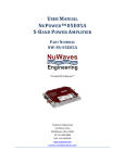
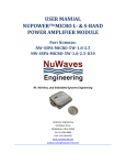
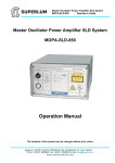
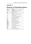
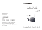
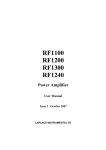
USER MANUAL NUPOWERTM MINI MULTI-OCTAVE POWER AMPLIFIER PART NUMBER: NW-SSPA-MINI-10W-0.225-2.6 Trusted RF Solutions.™ NuWaves Engineering 132 Edison Drive Middletown, Ohio 45044 PH: 513-360-0800 FAX: 513-539-8782 www.nuwaves.com [email protected] NuPowerTM Mini Multi-Octave PA User Manual 1 NUPOWERTM PRODUCT LINE OVERVIEW The NuPower family of solid state RF power amplifier (PA) modules is designed to meet the demanding needs of the Aerospace & Defense, Industrial, and Commercial markets. Based on the latest gallium nitride (GaN) technology, NuPower’s power efficiency and miniature form factor make it ideal for size, weight, and power-constrained broadband RF telemetry and tactical communications systems. NUPOWERTM PRODUCT LINE HIGHLIGHTS 1.1 High Performance: Unique combination of broadband coverage, miniature form factors, and high efficiency. Enclosures: The NuPower family of power amplifiers is housed in a silver nickel plated aluminum enclosure with mounting holes incorporated into the chassis. Completely Characterized: The NuPower family of solid state power amplifiers has been completely characterized over temperature, voltage, and frequency. These high-performance modules offer significant value for the OEM user or the Systems Integrator. User Friendly: Reverse-Voltage & Over-Voltage protection and regulator thermal shutdown provide defenses against user interface issues. High Reliability: NuWaves’ selection of conservatively rated components provides high reliability. Each NuPower is inspected to IPC-A-610 Class II quality standards. Applications: Unmanned Aircraft Systems (UAS) • Unmanned Ground Vehicles (UGV) • Unmanned Surface Vehicles (USV) • Broadband RF Telemetry • RF Communication Systems • Software Defined Radios • Test Labs Available Options: o o Fan-cooled heat sink with North American AC/DC wall plug adapter Labeled interface cable with banana jack plugs Document A6027-1000-1201 Rev 1.2 1 NuPowerTM Mini Multi-Octave PA User Manual 2 NUPOWERTM MINI MULTI-OCTAVE PA OVERVIEW The NuPowerTM Mini Multi-Octave Power Amplifier (MOPA) is a highly efficient, miniature solid state power amplifier that provides over 10 watts (typical) of RF power across multiple octaves, from high VHF through S-band. Based on the latest gallium nitride (GaN) technology, NuPower Mini MOPA’s power efficiency and 1.95 cubic inch form factor make it ideal for size, weight, and power-constrained broadband RF telemetry and tactical communication systems. The NuPower Mini MOPA’s rugged chassis allows the system integrator to easily incorporate the unit into a platform operating in harsh environments with limited space, such as small Unmanned Aircraft Systems (UAS). +5.5 VDC SCLK DIN ATTN EN 4.8 VDC +5 VDC REGULATOR LT1763-5 4.8 VDC PWR GOOD -BIAS1 VDC SW -BIAS2 VDC SW RF OUT +40dBm RF IN 225 MHz to 2600 MHz 0dBm EQUALIZER Gain=14dB Figure 1: NuPower Mini MOPA Functional Diagram 2.1 NUPOWER MINI MULTI-OCTAVE PA SPECIFICATIONS The subsequent tables in this section outline the NuPower Mini MOPA’s performance specifications. Table 1: NuPower Mini MOPA Electrical Specifications Parameter Specification Frequency Range 225 MHz to 2.6 GHz RF Output Power 10 Watts (typ)* / 7 Watts (min) RF Gain 40 dB (min) 2nd Harmonic ≤-13 dBc Supply Voltage +11 to +32 VDC Current Consumption 1.4 A @ +28 VDC (typ) Nominal Input Drive Level 0 dBm Document A6027-1000-1201 Rev 1.2 2 NuPowerTM Mini Multi-Octave PA User Manual Maximum Input Drive Level (No damage) +10 dBm Power Amplifier Enable GND On Impedance 50 Ω *The NuPower Mini MOPA will provide 10 watts minimum RF output power across 225 MHz to 2.6 GHz with an input drive level of +3 dBm. Table 2: NuPower Mini MOPA Environmental Specifications Operating Conditions Specification Operating Temperature for Continuous Operation (>5 minutes) -30 to +55 oC (ambient) -30 to +60 oC (baseplate) Operating Temperature for 20% Duty Cycle -30 to +60 oC (ambient) -30 to +65 oC (baseplate) Storage Temperature -40 to +85 oC Table 3: NuPower Mini MOPA Mean Time Between Failure (MTBF) Conditions Hours Ground Benign (GB) 126,690 Airborne Inhabited Cargo (AIC) 14,800 Airborne Inhabited Fighter (AIF) 10,650 Airborne Uninhabited Cargo (AUC) 8,400 Airborne Uninhabited Fighter (AUF) 5,800 Document A6027-1000-1201 Rev 1.2 3 NuPowerTM Mini Multi-Octave PA User Manual 2.2 NUPOWER MINI MULTI-OCTAVE PA MECHANICAL SPECIFICATIONS Figure 2: NuPower Mini MOPA Mechanical Outline Table 4: NuPower Mini MOPA Mechanical Specifications Parameter Specification RF Connectors SMA (female) Control / Power Interface Connector Dimensions (L x W x H) 9 Pin Micro-D (socket) 2.340” x 1.960” x 0.425” Weight 2 oz. Document A6027-1000-1201 Rev 1.2 4 NuPowerTM Mini Multi-Octave PA User Manual 2.3 HEAT SINKING The NuPower Mini MOPA is offered as a stand-alone module or with a kit, which also includes a fancooled heatsink with an AC / DC adapter, and an interface cable. Figure 3: The NuPower PA Kit offers “out-of-the-box” operation for the user. The fan-cooled heatsink with an AC / DC adapter is shown with an example PA (NuPower Mini MOPA not shown). Caution: The use of external heat-sinking is required especially for those applications requiring high duty cycle operation (e.g. continuous wave) or for extended on-time testing. Operation without a proper heat sink under these conditions will cause permanent damage to the product and will void the product warranty. The external heatsink thermal resistance requirements are: <0.35 ˚C/W for operation up to 40 ˚C ambient <0.20 ˚C/W for operation up to 55 ˚C ambient 3 SETUP AND OPERATION This section provides specific details for proper operation of the NuPower Mini MOPA module. Following these guidelines will prevent damage to the power amplifier or external equipment. 3.1 POWER SUPPLY REQUIREMENTS To operate the NuPower Mini MOPA, ensure that the power supply has adequate overhead to source the current demand of the RF power amplifier. The power supply source must provide a typical voltage of +28 VDC with greater than 3 amps capability. Document A6027-1000-1201 Rev 1.2 5 NuPowerTM Mini Multi-Octave PA User Manual 3.2 CONNECTING A PROPER LOAD TO THE ANTENNA TERMINAL To prevent damage to the PA, the antenna terminal must be terminated into a 50 Ω load. Examples of a proper load include: 3.3 Directly connecting to an antenna specified for the frequency range (225 MHz to 2.6 GHz). Connecting to an inappropriate antenna may result in damage to the PA module. Connecting to a proper antenna through a 50 Ω transmission line or coaxial cable. Avoid using damaged cables or corroded connectors while attaching the unit to an antenna. Terminating the antenna terminal into a 50 Ω power attenuator with minimum 20 dB attenuation. Connecting to a load capable of dissipating the RF power from the PA module. Loads capable of handling 20 Watts (min) are recommended. POWERING-UP THE MINI MOPA The NuPower Mini MOPA must be terminated to a proper load before power is applied. Refer to Section 3.2 for the specifications of the proper load. After the PA is properly terminated, the interface cable can be connected to the unit and power can be applied. The PA is now ready for operation. 3.4 TRANSMIT TURN-ON TIME Caution: Do not apply transmit data until the PA module is at full power. This will prevent loss of data at the beginning of a message. The NuPower Mini MOPA is at full power approximately 500 µS after the RF Enable line goes low (ground). Therefore, transmit data can be applied to the input after 500 µS without loss of data. 3.5 RF OUTPUT POWER VS. SUPPLY VOLTAGE Although the NuPower Mini MOPA was designed for +28 VDC operation, the module is capable of providing suitable RF power output over a broad range of supply voltages: +9 VDC to +32 VDC. 3.6 POWER BACK-OFF MODE The NuPower Mini MOPA is designed to allow the user to reduce, or “back-off,” the output power in support of linear waveform operation or to trade off output power in exchange for lower power consumption. The amount of power back-off is assuming a 0 dBm drive level to the PA module. Pins 7 & 9 on the CTRL/PWR interface connector are designated to allow such operation. Table 5 depicts the pin configurations to achieve low, medium, and high back-off settings, where “N/C” is an indication to leave the pin floating (i.e. not connected) since the pin is tied high internally, and where “GND” means grounding the pin. Due to the broadband nature of the unit, the amount of attenuation is an approximation for each respective setting as shown in Table 5, dependant on operational frequency and other factors, including unit-to-unit power variation. Document A6027-1000-1201 Rev 1.2 6 NuPowerTM Mini Multi-Octave PA User Manual Table 5: Power Back-off Settings Attenuation Settings Pin 7 Pin 9 Full power / No attenuation N/C N/C -6 dB (low) GND GND -9 dB (med) GND N/C -12 dB (high) N/C GND 4 HARDWARE INTERFACE The RF Input connector is SMA (female). The RF Output connector is SMA (female). The pin-out definitions for the 9 pin Micro-D socket connector are provided in Table 6. In a typical installation, the PA module is mated to a host controller board via a cable harness. The RF Out SMA connector is the antenna connection. This connection should always be loaded into 50 Ω, otherwise the PA could be damaged. 4.1 INTERFACE CABLE HARNESS The cable harness that connects the host controller to the 9 pin Micro-D connector of the NuPower Mini MOPA is made up of 9 wires. Table 6: NuPower Mini MOPA Interface Pin-Out Definitions Pin No. Pin Name I/0 Description 1, 2 V Supply I Primary Power (+28 VDC) 3, 4 GND I Signal and Power Ground 5 RF Enable I Transmit Control 6 N.C. - N/A 7 Power Back-off I Power Back-off mode, see Table 5 8 Temp Flag 0 Over-temp Indicator 9 Power Back-off I Power Back-off mode, see Table 5 Document A6027-1000-1201 Rev 1.2 7 NuPowerTM Mini Multi-Octave PA User Manual Figure 4: Micro-D Socket Locations 4.2 DC POWER The nominal supply voltage for the NuPower Mini MOPA is +28 VDC; however, the amplifier module is able to support operation over a supply voltage range of +9 to +32 VDC. 4.3 GROUND The signal and power grounds are tied together in the PA module. 4.4 RF ENABLE This signal is the logic control input that designates whether the unit is in transmit or standby mode. The RF Enable line is pulled high internally placing the PA module in standby mode. If the pin is left floating (i.e. not connected), the unit will default to standby mode. Grounding the pin (i.e. a voltage below +0.2 VDC) places the unit in transmit mode. The user can either connect the RF Enable line to pins 3 & 4 on the CTRL/PWR interface connector, or an open drain logic line capable of sinking 500 µA to place the unit in transmit mode. 4.5 TEMP FLAG This signal is an output to indicate an over-temperature condition in the NuPower Mini MOPA. A logic high (+5 VDC) indicates normal operation, while a logic low (0 VDC) indicates an over-temperature condition. The NuPower Mini MOPA incorporates internal logic circuitry that turns off the DC bias to the RF transistors. Caution: The amplifier should be shut down and allowed to cool off when the overtemperature flag is set high to avoid damage to the module. Document A6027-1000-1201 Rev 1.2 8 NuPowerTM Mini Multi-Octave PA User Manual 5 GETTING HELP - APPLICATIONS ENGINEERING NuWaves Engineering offers technical support for basic configuration help and troubleshooting, Monday through Friday, 8 a.m. to 5 p.m. Eastern Time. Technical Assistance and Application Engineering: Mr. Kevin Harrison (513) 360-0800 Ext. 313 FAX: (513) 539-8782 Email: [email protected] Sales: Mr. Bam Huon (513) 360-0800 Ext. 322 FAX: (513) 539-8782 Email: [email protected] NuWaves Home Page: www.nuwaves.com Product Warranty: http://nuwaves.com/wp-content/uploads/2011/04/NuWaves_Warranty__Repair.pdf 5.1 GENERAL INFORMATION Copyright © 2006 - 2013 NuWaves Ltd. All rights reserved. The information contained in this user manual is copyright protected. NuWaves reserves the right to make periodic modifications and product improvements to the NuPower product line and the associated documentation. Document A6027-1000-1201 Rev 1.2 9